1
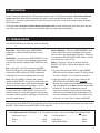
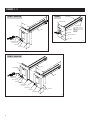
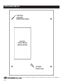
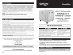
MODELS 1910 & 1930
Ultraviolet Germicidal Lamps
Installation and Service Manual
I. SAFETY INSTRUCTIONS
Please read the safety and installation instructions carefully to help ensure a correct and SAFE installation of the Aprilaire
Ultraviolet Germicidal Lamp.
WARNING
Ultraviolet light is harmful to eyes
and skin. Never look at light
produced by this lamp. Unplug lamp
before servicing.
Electrical shock from 120 VAC may
cause serious injury. Disconnect
power before starting installation and
keep disconnected until complete.
The lamp has a grounding-type (3
prong) plug that will fit only into a
grounding-type power outlet. Do not
alter plug in any way.
Sharp edges may cause personal
injury. Use care when cutting and
handling sheet metal.
Lamp may cause personal injury in
the form of burns or cuts. Wear
protective gloves and safety glasses
when handling lamp. To prevent
burns, unplug lamp and allow to cool
for several minutes before servicing.
If lamp is broken, refer to lamp
disposal section of this manual.
CAUTION
1. UV light can cause color changes or structural degradation of
plastics, rubber, paper, and other non-metallic materials used in
the HVAC system.
• Install lamp in location that prevents exposure of plastics, rubber,
paper, and other non-metallic materials to UV light, or shield such
materials with aluminum tape, sheet metal, or metal conduit.
• Shield electrical wires that receive direct or reflected UV
radiation with aluminum tape, sheet metal, or conduit.
• Do not install in flex duct. If the UV resistance of the flex duct is
not known, install lamp at least 6 feet away from flex duct. If the
flex duct is UV resistant, lamp may be installed as close as 3 feet.
• Install lamp at least 8 inches away from equipment or
components made with UV resistant plastic. If equipment or
components are not made with UV resistant plastic – or if the UV
resistance of the material is unknown – shield with aluminum
tape or sheet metal.
2. Water may damage lamp.
• Do not install lamp inside or under an “A” coil.
• Install lamp at least 3 inches away from an “A” coil.
• Install lamp at least 8 inches away from a horizontal coil.
• Do not install lamp below a humidifier or any source of water.
II. APPLICATION
Aprilaire Ultraviolet Germicidal Lamps are designed for the treatment of evaporator coils used in air conditioners or heat
pumps in a HVAC system. The lamps will kill microorganisms growing on evaporator coils and drain pans and prevent further
growth. The units are designed for continuous lamp operation. Model 1910 is a Single Base Unit and Model 1930 is a Dual
Base Unit. The units are 120 VAC / 60 Hz. See Figures 1 - 3 for unit schematics.
© Research Products Corp.
III. INSTALLATION
• The installation should be done by a qualified HVAC
contractor.
• Read all safety instructions at the beginning of this manual.
Failure to do so could lead to personal injury and/or
equipment damage.
• In cases where fungi and/or bacteria are already present on
the evaporator coil, it is recommended that a qualified HVAC
service technician clean the coil before the installation of
the UV Lamp. Because the Aprilaire Ultraviolet Germicidal
Lamp quickly kills fungi and bacteria, there could be an
initial period of temporarily increased levels of airborne
decay products if the coil is not cleaned before installation.
• Do not wire this unit into a switched outlet or operate the
unit intermittently; this will significantly reduce the life and
effectiveness of the lamp.
• Except where noted, these instructions apply to Models 1910
and 1930. For the Model 1930, install the primary or LEFT
UNIT FIRST, then the secondary or RIGHT UNIT. The two
units are connected by a power cord 29” long. See Figure 2.
• The tools and equipment required to complete this
installation include: the template; a tape measure; 5/16” &
11/32” nut driver (or a socket set); 1/8”, 1/4”, & 3/8” drill bits;
a drill; and a pair of left-handed and right-handed sheet
metal cutters. A digital multi-meter might also be needed.
1. Determine a mounting location for the lamp. Use the
criteria below to select a proper location:
a. The lamps are intended for evaporator coil treatment.
See Figures 4 - 7 for guidelines on mounting locations.
b. Install lamp in location that prevents exposure of
plastics, rubber, paper, and other non-metallic materials
to UV light, or shield such materials with aluminum tape,
sheet metal, or metal conduit. See CAUTION statements
at beginning of manual for more details.
c. To protect lamp, do not install lamp below any source
of water.
d. Install units so that LAMP ASSEMBLY is at least 3
inches away from evaporator coil surface.
e. Install lamp in a location that can be easily accessed.
Allow 20 inch clearance to slide lamp in and out of
duct. See lamp dimensions in Figures 1 & 2. For Model
1930, when considering mounting location, keep in
mind the 29” cord length that connects the LEFT and
RIGHT units.
f. Be certain the area in the duct where you intend to drill
and cut is free of any obstructions or components that
would be damaged by the installation or interfere with
the installation.
g. While keeping these guidelines in mind, the more
direct exposure the coil and drain pan receive, the
greater the benefit the lamps will have.
Note: For horizontal coils larger than 24” in height it is recommended that a Model 1930 or two Model 1910s be used.
2. Using the template that is supplied with this manual,
mark the location of a rectangular opening for the LAMP
ASSEMBLY and 5 holes, 4 of which will be required to
mount the UNIT BASE and 1 for the HOLE FOR SIGHT
GLASS. When considering placement of lamp, note that
the LAMP ASSEMBLY is off-center, relative to the base.
3. Carefully inspect the HVAC system and make sure that
no damage will occur as a result of drilling the 5 holes.
4. Drill four 1/8” diameter holes at the marked location of
the 4 mounting holes.
5. Drill a 1/4” hole at the marked location for the hole that
allows UV light to be seen through the SIGHT GLASS.
6. Drill a 3/8” diameter hole into the duct at one corner of
the rectangular slot.
7. Starting at the 3/8” hole, cut a 2 1/4” x 4 1/8” rectangular
opening.
8. Check that the UNIT BASE, with the LAMP ASSEMBLY
attached, can be placed through the rectangular opening
in the duct and that the UNIT BASE fully contacts the duct.
9. Apply foam tape (included) to the side of the UNIT BASE
that is in contact with the duct. The purpose of the foam
tape is to prevent UV light from being seen through
cracks between the UNIT BASE and duct.
10. Use alcohol to remove any dirt and/or fingerprints from
the LAMP.
11. Attach UNIT BASE, with LAMP ASSEMBLY in place,
using 4 self-tapping sheet metal screws and the predrilled holes.
12. Attach the UNIT HOUSING and secure it with two NUTS
that are placed over the studs mounted on the base.
13. Repeat steps 2-11 for the RIGHT UNIT of Model 1930.
14. Place three WARNING labels (included) on the duct: one
on the duct near the UV lamp and the other two on
opposite sides of the plenum, near the furnace/air
handler.
15. Plug the POWER CORD into a 120 VAC power outlet that
is always energized.
16.Turn the lamp’s ON/OFF SWITCH to the ‘On’ position.
(1930 has ON/OFF SWITCH on each unit.)
3
IV. CHECK LAMP OPERATION
Check operation of the lamp using the following procedure. These instructions apply to Model 1910 and both units that make
up Model 1930.
1. Plug the lamp’s POWER CORD into a standard 120 VAC
outlet that is always energized.
2. Turn the lamp’s ON/OFF SWITCH to the ‘On’ position.
(1930 has ON/OFF SWITCH on each unit.)
3. Look at the SIGHT GLASS located in the bottom center of
the UNIT HOUSING. (See Figure 1). If the lamp is operating
correctly, the SIGHT GLASS will be illuminated by blue light.
If not, see the ‘Troubleshooting’ section for additional steps.
4. Look for any stray UV light and apply the proper caulk or
aluminum tape to eliminate.
V. ANNUAL LAMP REPLACEMENT
The Aprilaire Ultraviolet Germicidal Lamp is designed for the lamp to be on at all times. After 9,000 hours of operation – 1 year
of constant use – the effectiveness of the lamp inside the unit diminishes and needs to be replaced. Rarely will a lamp burn
out in one year of continuous use; replacement is necessary because the lamp’s intensity decreases. Installation of the
replacement lamp (Aprilaire Service Part #90) is best handled by a qualified HVAC Service Contractor.
Lamp Replacement Instructions (see Figures 1 - 3):
a. Switch ON/OFF SWITCH to ‘Off’ and unplug POWER
CORD. Wait several minutes for lamp to cool before
proceeding.
b. Loosen NUTS that secure UNIT HOUSING to BASE then
remove UNIT HOUSING.
g. Use alcohol to remove any dirt and/or fingerprints from
the new LAMP.
h. Return LAMP ASSEMBLY to BASE and fasten LAMP
DOOR SCREW.
c. Loosen LAMP DOOR SCREW that secures LAMP DOOR to
BASE.
i. Put UNIT HOUSING back in place and fasten NUTS. Be
sure UNIT HOUSING rests completely on the BASE and
that all wiring is fully inside.
d. Carefully pull LAMP ASSEMBLY out from duct. This
requires that you slightly lift up and tilt forward the LAMP
ASSEMBLY while pulling out from the BASE.
j. Plug in POWER CORD and turn ON/OFF SWITCH to ‘On.’ If
the lamp is operating correctly, the SIGHT GLASS will be
illuminated by blue light.
e. Remove LAMP by pulling it out from LAMP SOCKET and
out from LAMP HOLDER.
k. In the Owner’s Manual, record the date the lamp was
replaced so that the date for next replacement is clear.
f. Install new, replacement LAMP (Aprilaire Service Part #90)
into LAMP SOCKET and LAMP HOLDER. Be sure LAMP is
fully inserted into LAMP SOCKET.
Under normal conditions, the Aprilaire Ultraviolet Germicidal Lamp should not require any maintenance other than annual
lamp replacement.
4
VI. LAMP DISPOSAL
As with a fluorescent light bulb, your UV lamp contains mercury and must be disposed of properly. Do not throw old lamps
into the trash. Many communities have agencies that take in mercury along with other materials – such as old paints,
solvents, etc. – that require special disposal. Please contact your municipal or county waste collection agency for proper
disposal procedures.
If a lamp is broken, do not use a vacuum cleaner to pick up the waste. Instead, sweep up the waste into a plastic bag and
seal. Contact your municipal or county waste collection agency for proper disposal procedures.
VII. TROUBLESHOOTING
If the SIGHT GLASS does not illuminate, check the following:
Power Cord – Verify that the lamp’s POWER CORD is
plugged into a standard 120 VAC outlet that is always
energized.
On/Off Switch – Verify that lamp’s ON/OFF SWITCH is in the
‘On,’ position. The switch is illuminated red when powered
and in the ‘On’ position. (1930 has ON/OFF SWITCH on each
unit.)
Fuse – If the lamp is still not illuminated, place ON/OFF
SWITCH to ‘Off’ position, unplug the lamp’s POWER CORD,
and check the FUSE. Look to see if FUSE is darkened or
visibly blown; or check fuse continuity with multi-meter.
Lamp – Verify that LAMP is not broken and is properly
seated into LAMP SOCKET. To check this, follow steps in the
‘Annual Lamp Replacement’ section with one exception: you
should not remove and replace lamp (Steps ‘e’ and ‘f’).
Instead, simply verify that lamp tube is not broken and that it
is firmly pushed into its’ LAMP SOCKET. If necessary, use
alcohol to remove any dirt and/or fingerprints from the lamp.
If the lamp is broken read the ‘Lamp Disposal’ section of this
manual for proper disposal.
Hole for Sight Glass – When the LAMP ASSEMBLY is back
in place and with the lamp still unplugged, check to see if
there is a hole in the duct behind the sight glass. See Figure
3 for location of HOLE FOR SIGHT GLASS. If there is no hole,
carefully drill one using a 1/4” bit.
Ballast – If the lamp is still not illuminated, check the
BALLAST. See Figures 8 & 9 for wiring diagrams of the
two units.
a. First check the input power. To do so, unplug POWER
CORD and check line voltage at outlet. The voltage should
be close to 120 VAC, if it is not contact an electrician.
b. If the input voltage is OK, check the resistance of the
BALLAST. Do this with POWER CORD unplugged.
Measure the resistance from the black lead on the input
side of the BALLAST to the blue lead on the output side of
the BALLAST. To contact the blue lead it may be
necessary to remove the lamp and put the multi-meter
probe into the corresponding lamp socket opening. The
resistance should be in the range of 7 to 12 ohms. If the
resistance is less than 7 ohms, replace the BALLAST.
If the resistance of the BALLAST is OK and everything else checks out, but the light still does not illuminate, the starter in the
BALLAST is likely shorted out and the BALLAST must be replaced.
List of Replacement Parts (See Figures 1 - 3). The replacement parts are the same for Model 1910 and Model 1930.
Replacement Lamp . . . . . . . . . . . . . . . . . . . . . . .#90
Fuse Cap & Holder . . . . . . . . . . . . . . . . . . . . . .#4413
Ballast . . . . . . . . . . . . . . . . . . . . . . . . . . . . . . . .#4411
Lamp Socket . . . . . . . . . . . . . . . . . . . . . . . . . . .#4414
Fuse . . . . . . . . . . . . . . . . . . . . . . . . . . . . . . . . . .#4412
Lighted On/Off Switch . . . . . . . . . . . . . . . . . . .#4415
5
FIGURES 1 - 3
FIGURE 1 – Model 1910
FIGURE 3
LAMP BRACKET
LAMP DOOR SCREW
17.5"
6.0"
LAMP HOLDER
NUT
LAMP ASSEMBLY IS MADE UP OF:
LAMP DOOR
LAMP
LAMP
LAMP SOCKET
LAMP BRACKET
LAMP HOLDER
LAMP DOOR
LAMP SOCKET
HOLE FOR SIGHT GLASS
UNIT BASE
8.5"
POWER CORD
90-680
ON/OFF SWITCH
FUSE & FUSE CAP
SIGHT GLASS
UNIT HOUSING
2.0"
90-678
FIGURE 2 – Model 1930
NUT
17.5"
LAMP
LEFT UNIT
6.0"
NUT
LAMP
POWER CORD
ON/OFF SWITCH
FUSE & FUSE CAP
SIGHT GLASS
UNIT HOUSING
8.5"
CONNECTOR CORD
(29" LONG)
ON/OFF SWITCH
RIGHT UNIT
SIGHT GLASS
UNIT HOUSING
2.0"
90-679
6
FIGURES 4 - 9
FIGURE 4 – Model 1910 on Horizontal Coil
FIGURE 5 – Model 1930 on Horizontal coil
RETURN
RETURN
MODEL 1930
(TOP INSTALLATION)
MODEL 1910
(TOP INSTALLATION)
LEFT UNIT
RIGHT UNIT
HORIZONTAL
COOLING COIL
HORIZONTAL
COOLING COIL
HORIZONTAL
FURNACE
HORIZONTAL
FURNACE
SUPPLY
SUPPLY
MODEL 1930
(SIDE INSTALLATION)
MODEL 1910
(SIDE INSTALLATION)
LEFT UNIT
RIGHT UNIT
90-681
90-682
FIGURE 6 – Model 1910 on “A” Coil
FIGURE 7 – Model 1930 on “A” Coil
NOTE: SIDE INSTALLATION OF 1910 ON
“A” COIL IS ACCEPTABLE IF OPPOSITE
COIL HAS ADEQUATE COVERAGE.
SEE SIDE INSTALLATION DRAWING
RETURN
SUPPLY
RETURN
SUPPLY
“A” COIL
“A” COIL
8" MIN. FROM LAMP TO TOP OF “A” COIL
FOR FRONT INSTALLATION
UPFLOW
FURNACE
MODEL 1910
(FRONT INSTALLATION)
3" MIN
FOR SIDE INSTALLATION
3" MIN
FOR SIDE INSTALLATION
24" MAX
(FOR 1910)
MODEL 1930
(FRONT INSTALLATION)
NOTE INSTALLATION
OF 1930 ON “A” COIL IS
ACCEPTABLE IF OPPOSITE COIL
HAS ADEQUATE COVERAGE.
SEE SIDE INSTALLATION DRAWING.
3" MAX
“A” COIL SIDE INSTALLATION
UPFLOW
FURNACE
3" MAX
“A” COIL SIDE INSTALLATION
90-683
FIGURE 8 – Model 1910
90-684
FIGURE 9
BLUE, RED, YELLOW, WHITE
BLUE, RED, YELLOW, WHITE
BALLAST
BALLAST
BLUE, RED, YELLOW, WHITE
TO LAMP
SOCKET
TO LAMP
SOCKET
SAFETY SWITCH
SAFETY
SWITCH
BALLAST
SAFETY SWITCH
BLACK
BLACK
BLACK
GREEN
GREEN
GREEN
WIRE NUTS
WIRE
NUTS
WIRE
NUTS
WHITE
TO LAMP
SOCKET
POWER CORD
CONNECTOR
CORD
POWER CORD
ON/OFF SWITCH
ON/OFF SWITCH
ON/OFF SWITCH
FUSE HOLDER
WHITE
90-686
WHITE
FUSE HOLDER
90-687
7
INSTALLATION TEMPLATE
.125 DRILL
4 PLACES
MOUNTING HOLES
CUT OUT
FOR UV BULB
INSTALLATION
.25 DRILL
SIGHT HOLE
90-685
1015 E. WASHINGTON AVE. • MADISON, WI 53703 • PHONE: 888/782-8638 • FAX: 608/257-4357 • www.aprilaire.com
B2203091