1
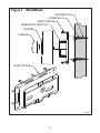
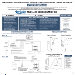
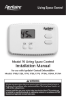
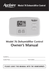
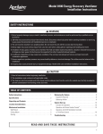
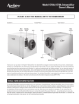
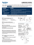
Manual
Humidifier Control
Safety and Installation Instructions
R E A D C O M P L E T E I N S TA L L AT I O N I N S T R U C T I O N S
A N D T E M P L AT E B E F O R E S TA R T I N G .
WARNING
ATTENTION INSTALLER: This product must be
installed by a qualified heating and air conditioning
contractor. Failure to do so could result in serious
injury from electrical shock.
THESE INSTALLATION INSTRUCTIONS ARE FOR
THE APRILAIRE MANUAL HUMIDIFIER CONTROL ONLY!
For Aprilaire® humidifier installation, follow Aprilaire
Humidifier Installation Instructions.
The Manual Humidifier Control (Part 4655) is designed for low
voltage service to control humidification equipment. An increase
in relative humidity (RH) expands the nylon ribbon which opens
the control switch to stop operation of the humidifier. A decrease
in RH reverses the process and closes the control switch.
WARNING
1. 120 volts may cause serious injury from electrical
shock. Disconnect electrical power to the furnace
before starting installation.
2. Sharp edges may cause serious injury from cuts.
Use care when cutting plenum openings and handling
ductwork.
CAUTION
1. Do not set humidity higher than recommended.
Condensation damage may result.
2. Do not set humidity up to recommended levels if there is
condensation on the inside of windows of any unheated
living space. Condensation damage may result.
3. Do not mount the Manual Humidifier Control on the
supply plenum or duct. The unit cannot withstand
supply temperatures and will malfunction.
4. Do not mount the Manual Humidifier Control downstream
of the bypass outlet. False humidity conditions will cause
the humidifier to operate incorrectly.
2
LOCATION
Control can be mounted on wall in living space or on return duct.
For Wall Mount:
• Locate on an inside wall of living area approximately 5’ above
the floor.
• Do not locate control in the direct path of drafts from open
doors and windows.
• Do not install where operation might be affected by lamps,
sunlight, fireplace, registers, radiators, concealed air ducts and
pipes, or room occupants.
• The basic rules for location of thermostats also apply to
humidifier controls.
For Duct Mount:
Locate on the furnace return air plenum or duct, at least 6”
upstream of the humidifier, humidifier bypass ductwork (if
applicable) or fresh air intake ductwork (if applicable).
GENERAL INSTRUCTIONS
• Do not mount the Humidifier Control on counter flow furnace.
Furnace malfunction will result in improper humidifier
operation.
• Be sure the Humidifier Control is installed on a 24 VAC circuit
only.
• Make sure no bare wires are exposed or insulation damaged.
• Make sure all splices are mechanically and electrically secure.
• To remove dirt or other foreign matter from the nylon ribbon
and control interior, dust lightly with a fine soft brush.
3
INSTALLING AND WIRING
Wall Installation:
1. Select location for the Humidifier Control on an inside wall.
Mount the Humidifier Control in a location where low voltage
wires from the furnace area are already in place, or can be
easily run.
2. Drill a 1/2” hole into the wall at the selected Humidifier
Control location.
3. Pull low voltage wires from the furnace area and through the
hole in the wall. Before mounting the Humidifier Control, the
hole in wall should be plugged to prevent drafts affecting the
Humidifier Control reading. All wiring should conform to the
National Electrical Code and local regulations.
4. (See Figure 1) Gently pull knob (A) from Humidifier Control
cover (B). Cover is held in place by snap clips. Remove cover
by pulling carefully. Do not touch the sensing element.
5. Pull low voltage leads through opening in base plate (D).
6. Attach wires to terminal screws on Humidifier Control.
(Note: If wires are “bunched” between Humidifier Control and
wall, base plate may become warped or cracked and
calibration may be affected.)
7. Remove the gasket (not required for wall mount). Attach base
plate with humidistat switch to the wall using two screws (E)
and two wall anchors (F), if necessary.
8. Reassemble Humidifier Control cover by snapping back in
place. Press on knob.
4
Figure 1 – Wall Mount
ANCHOR F (x2)
SCREW E (x2)
BASE PLATE D
HUMIDISTAT SWITCH C
COVER B
KNOB A
BASE PLATE D
90-1228
5
Duct (sheet metal) Installation:
1. Select Humidifier Control location on furnace return air duct.
2. Use the attached template to mark the duct opening.
3. Carefully cut the opening in the duct.
4. (See Figure 2) Gently pull knob (A) from Humidifier Control
cover (B). Cover is held in place by snap clips. Remove cover
by pulling carefully. Do not touch the sensing element.
5. Run low voltage leads to control location. All wiring should
conform to the National Electrical Code and local regulations.
6. Attach low voltage wires.
7. Make sure that the gasket (G) is in place. Use four sheet metal
screws (H) (not provided) to mount the Humidifier Control in
the duct opening.
8. Reassemble Humidifier Control cover, guiding the low voltage
wires through the cover side opening. Press on knob.
6
Figure 2 – Sheet Metal Duct Mount
GASKET G
SCREW H (x4)
BASE PLATE D
HUMIDISTAT SWITCH C
COVER B
KNOB A
INSIDE OF
RETURN
DUCT
RETURN DUCT
90-1229
7
Duct (fiber board) Installation:
1. Select Humidifier Control location on furnace return air duct.
2. Cut a rectangular hole in the duct board, no smaller than
5-3/4 inches long by 3-3/4 inches wide.
3. Cut a rectangular piece of sheet metal to fit behind the hole
in duct board for mounting the Humidifier Control.
4. Use the attached template to mark the sheet metal opening
for the Humidifier Control.
5. Carefully cut the opening in the sheet metal.
6. (See Figure 3) Gently pull knob (A) from Humidifier Control
cover (B). Cover is held in place by snap clips. Remove cover
by pulling carefully. Do not touch the sensing element.
7. Run low voltage leads to control location. All wiring should
conform to the National Electrical Code and local regulations.
8. Attach low voltage wires.
9. Make sure that the gasket (G) is in place. Use four sheet
metal screws (H) (not provided) to mount the Humidifier
Control in the sheet metal opening.
10. Reassemble Humidifier Control cover, guiding the low voltage
wires through the cover side opening. Press on knob.
11. Secure the sheet metal plate inside the duct.
8
Figure 3 – Fiber Board Duct Mount
GASKET G
SCREW H (x4)
HUMIDISTAT SWITCH C
COVER B
KNOB A
INSIDE OF
RETURN
DUCT
BASE PLATE D
SHEET METAL
PLATE
RETURN DUCT
RETURN
DUCT
SHEET METAL
PLATE
CUT OPENING IN
RETURN DUCT
90-1230
9
SPECIFICATIONS
RANGE . . . . . . . . . . . . . . . . . . . . . . . . . . . . . . . . . . . . 15% to 50%
OPERATIONAL DIFFERENTIAL . . . . . . . . . . . 8% RH NOMINAL
DIMENSIONS (Inches)
Length . . . . . . . . . . . . . . . . . . . . . . . . . . . . . . . . . . . . . . . . . 5-1/8”
Height . . . . . . . . . . . . . . . . . . . . . . . . . . . . . . . . . . . . . . . . . 3-3/8”
Depth . . . . . . . . . . . . . . . . . . . . . . . . . . . . . . . . . . . . . . . 1-15/16”
ELECTRICAL DATA
SPST Switch
2 wires
24 volts A.C.
Maximum load (contacts) 5.2 amps.
10
11
5. USING 4 SHEET METAL SCREWS, INSTALL HUMIDIFIER
CONTROL IN OPENING.
4. REMOVE TEMPLATE AND ACCURATELY CUT OPENING.
3. TRACE OUTSIDE EDGES OF TEMPLATE.
2. PLACE TEMPLATE ON THE SHEET METAL RETURN PLENUM
UPSTREAM OF (BEFORE) THE HUMIDIFIER CONNECTION.
1. CUT OUT TEMPLATE ALONG EDGES.
TEMPLATE SIZE: 4-5/32” x 2-7/16”
TOP
INSTALLATION TEMPLATE
For Use On Sheet Metal Return Plenum
RESEARCH PRODUCTS CORPORATION
P.O. BOX 1467 • MADISON,WI 53701-1467
Call 800/334-6011 • FAX 608/257-4357
10007235 8.07
B2204275A
Printed in USA