1
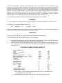
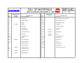
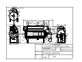
DYNATHERM
SERVICE
MANUAL
BETHELEHEM CRUSADE-A-THERM
Manufactured By
Dynatherm Boilers
43 E Cherry Road
Quakertown, PA 18951
(215) 536-4078 Fax: (215) 536-8960
www.dynathermboiler.com
1
TABLE OF CONTENTS
INSTALLING BETHLEHEM CRUSADE-A-THERM
INSTALLING JACKET ............................................................................................................................................3
PIPING TO BOILER .................................................................................................................................................3
FUEL LINES TO BURNER......................................................................................................................................3
ELECTRICAL WIRING ...........................................................................................................................................3
FLUE GAS OUTLET ................................................................................................................................................3
DOMESTIC HOT WATER.......................................................................................................................................3
WATER SUPPLY TO BOILER................................................................................................................................3
FUEL SUPPLY TO BURNER ..................................................................................................................................4
STARTING BETHLEHEM CRUSADE-A-THERM ...................................................................................................4
ADJUSTING BETHLEHEM CRUSADE-A-THERM .................................................................................................4
COMBUSTION EFFICIENCY OIL PRESSURE, ETC............................................................................................4
NOZZLES..................................................................................................................................................................5
CONTROLS ..............................................................................................................................................................5
CRUSADE-A-THERM RATINGS AND DATA......................................................................................................5
DRAWINGS
BILL OF MATERIALS.............................................................................................................................................7
GENERAL ARRANGEMENT .................................................................................................................................8
2
INSTALLING BETHLEHEM CRUSADE-A-THERM
INSTALLING JACKET
Remove the proper knockouts and place the top panel over the unit, put the side panels in place and slide the
edges of the top panel down over the side panels; lock the panels together with bolts and nuts, and sheet metal
screws provided for that purpose; close the two ends by putting the respective door panels in place.
PIPING TO BOILER
Connect the riser and return piping to the Crusade-A-Therm. The riser should be run a vertical distance of at
least 12" above the boiler outlet. The return must be run horizontally and at right angles to the centerline of the
boiler for a distance of at least 13" so as to clear the side panel of the jacket.
FUEL LINES TO BURNER
Connect the suction line from the oil storage tank to the pump using an unbroken length of copper tubing and
flare type fittings. The suction line should pass within the jacket immediately below and through the same
opening as the return piping or through one of the openings provided in side panels. If an outside storage tank is
used, a return line to the tank must be provided.
ELECTRICAL WIRING
All auxiliary electrical equipment and wiring are to be installed by an experienced electrician in accordance with
the National Electrical Code and with Local Ordinances. Wiring is to be done in BX cable or conduit.
All connections must be soldered or approved connectors used. Minimum conductor size should be #14. See
rear of Manual for electrical wiring diagrams.
The thermostat is to be installed preferably on the main floor in one of the normally occupied rooms, the living
room being a desirable location in most instances.
Locate the thermostat not more than five feet above the floor in a position where it will be least affected by draft,
radiation, the cooling affect of a window or an outside wall. When in thermostat leads are brought through a hole
made in the wall, the space around the leads should be packed with asbestos wool. Connect the power service
line from a switch on the wall to the two wires in the junction box marked "H", for hot and "G" for ground. This
service line should pass within the jacket immediately below and through the same opening as the return piping
or through on e of the openings provided in the side panels. When the Crusade-A-Therm is used in connection
with steam, vapor, or gravity -- hot water systems, connect the thermostat in the low voltage terminals in the
combustion control.
FLUE GAS OUTLET
Connect the flue gas outlet of the Crusade-A-Therm with the chimney using 6" dia. Galvanized stove pipe. The
chimney should not be smaller than 8" round or square.
DOMESTIC HOT WATER
Make connections to the hot water coil and provide valves for back flushing the coil.
WATER SUPPLY TO BOILER
Connect water supply to return piping of the unit. Fill boiler and system with water and check for leaks.
3
FUEL SUPPLY TO BURNER
The Bethlehem Crusade-A-Therm is listed by the Underwriters to burn #2 Commercial Standard grade fuel oil.
Since the grades marketed by different oil distributors vary, it is advantageous for you to be familiar with the
quality of fuels available in your territory.
STARTING BETHLEHEM CRUSADE-A-THERM
Before starting burner:
1.
2.
3.
4.
5.
6.
7.
8.
9.
10.
11.
12.
Check electrical connections.
Check oil connections to tank and pump.
See that the electrodes are properly positioned. The electrodes should be 3/8" above the center of the
nozzle tip, and 1/16" forward of the face of the nozzle tip. The gap should be 3/16" wide. See that the
electrodes are spaced 1/4" from any grounded metal. The face of the nozzle tip should be 1/4" behind
the orifice place in the nosepiece.
Oil Motor: The motors have sleeve bearings and are wick oiled. Fill the reservoir with high-grade spindle
oil that will flow at low temperatures.
See that the proper fuel oil is in the tank. (The Bethlehem Crusade-A-Therm has been approved to burn
not heavier than Commercial Standard #2 Fuel Oil.)
Be sure that the combustion control is in the starting position.
See that all joints of smoke pipe are tightly made up and sealed to the chimney.
See that the system is fully supplied with water as required.
Set room thermostat at a point slightly above room temperature.
See that the boiler control is in the "ON" position.
Open valve in fuel oil line.
Gravity Feed Installations:
To vent the fuel unit on a single pipe system, remove the plug located in the side of the
regulating valve chamber.
With the fuel unit in operation, allow enough oil to drain out to purge the entire system of
air. Catch the overflow in a suitable container. This same tapping is for use of the
pressure gauge when setting the Crusade-A-Therm for 11% CO2.
Sub-Gravity Installations:
These must have a return line from the fuel unit to the storage tank. In all other respects,
the starting instructions are the same as for gravity feed installations.
ADJUSTING BETHLEHEM CRUSADE-A-THERM
COMBUSTION EFFICIENCY OIL PRESSURE, ETC.
The Bethlehem Crusade-A-Therm by virtue of its construction is distinctive in its operation. Positive pressure is
generated throughout the combustion zone thus eliminating the necessity for ideal draft conditions -- the socalled "chimney pull" -- that most conventional types of burners depend upon. It is designed to operate at its
maximum efficiency when producing its rated output with 11% CO2 in the combustion gas, and any other setting
will result in increased stack temperature and lowered efficiency.
For this reason it is not possible to adjust the burner by observing the color or character of the flame. THE FLUE
GASES MUST BE ANALYZED AND THE CO2 CONTENT CHECKED. TO DO THIS PROCEED AS FOLLOWS:
Allow the burner to operate for about 10 minutes, them remove the pipe plug from the smoke pipe elbow at the
upper rear of the unit. Insert the sampling tube of an Orsat and pump a representative sample of flue gas into
the Orsat.
4
These for the CO2 content. If analysis shows more or less than 11% CO2, either increase or decrease the oil
pressure until the correct treading is obtained. Increasing the oil pressure increase the CO2 content; decreasing
the oil pressure decreases the CO2 content. The oil pressure can be varied by removing the cover over the
adjusting screw and turning this screw. To increase oil pressure, turn screw clockwise and to decrease oil
pressure, turn screw counter-clockwise. Be sure to replace cover and gasket when adjustment is completed.
When 11% CO2 is obtained, the oil pressure should be in the range of 80 lbs. to 125 lbs. If oil pressure is below
80 lbs. when 11% CO2 is obtained, install the next smaller size nozzle. If above 125 lbs. when 11% CO2 is
obtained, install the next larger size nozzle and again adjust the oil pressure for 11% CO2.
USE A PRESSURE GAUGE WHEN INCREASING OR DECREASING OIL PRESSURE.
NOZZLES
It is very important that the proper nozzle size and spray angle be used with the Bethlehem Crusade-A-Therm.
The following sizes and spray angles must be used:
#36
1.00/30 deg.
or
1.25/30 deg.
Hollow
If other than 30 degree nozzles are used, the result will be carbon deposits in the nose piece and combustion
tube, which will cause unsatisfactory operation and safety shut down.
CONTROLS
Carefully check the operation of all controls and make sure that they function properly.
IF THE OPERATION IS NOT NORMAL, CHECK THE FOLLOWING:
1.
2.
If the motor does not start, trip the safety switch button on the combustion control. If this fails to produce
the desired result, follow the instructions in the control instruction pages.
If motor starts and "safety shut down" continues, the oil systems should be rechecked for leaks or air
traps. Check the fuel unit; if it is air-bound, remove pipe plug and allow air to escape, and then replace
pipe plug when oil
CRUSADE-A-THERM RATINGS AND DATA
BOILER NUMBER 36
Steam
)
Vapor
)- Net Rating*
Hot Water )
Boiler Output BTU per hr.
)_ Gross
Boiler Output-Kilogram-Calorie ) Rating**
Nozzle Size Nominal
Firing Rate
Chimney Size
Boiler Outlet Size
Boiler Return Size
Safety Valve Size
Crate -- width
-- length
-- height
Shipping weight -- crated
Shipping weight of Jacket
sq. ft.
sq. ft.
sq. ft.
1000's
1000's
gal/hr
gal/hr
in
in
in
in
in
in
in
lbs
lbs
350
375
560
120
30
1.00
1.12
8x8
3
2
1
20 1/2
62
36
775
150
* NET RATING = Actual Standing Radiation with piping, pick up, and domestic hot
water allowances already made
** GROSS RATING = Actual boiler Output which is 30% greater than Net Rating.
5
BILL OF MATERIALS
DYNATHERM
SPARE PARTS
CODE
919.100
DWG G-367
SHEET
WHIRLING FLAME
1
BETHLEHEM CRUSADE-A-THERM
SPARE PARTS
CODE
DESCRIPTION
Electrode Bracket
NO.
74
7L
Knurled Pin
79
Temperature Pressure Gauge
13 N
Oil Pipe Spider
80 Ns
Boiler Body - Steam
15-5
Motor
80 Nw
Boiler Body - Water
Nozzle
110
Hinge Pin
25
Electrode
116 L
Tank Heater Coil
35
Transformer
117
Return Ell
41
ProtectoRelay
127 E
210.000
Scroll
46
Junction Box Cover
137 J
207.003
Orifice Plate
67 N
Housing
144
503.006
Liners
67 N-1
Coupling Cover
146
921.001
Refractory Insert
69 A
Elbow
147 G
Air Silencer
Flue Connection
157
Nose Piece
70 G
Clean Out Cover
157 A
Sleeve
70 J
Clean Out Cover
158 A
Nozzle Plate
71
Peephole Slide
160
Delay Relay
Peephole Cover
DT 36
Tankless Heater Coil
NO.
6C
17
69 M
72
511.000
200.103
202.102
72 A
73
Peephole Gasket
102.316
Peephole Lever
100.317
Peephole Glass
6
DESCRIPTION
Fuel Unit
REVISED
2 13/16"
4 15/16"
DRAWINGS
CRUSADE-A-THERM
DT-36 TANKLESS COIL
1/2" PIPE CONNECTIONS
10 5/16"
11 9/16"
BILL OF MATERIALS
61"
36"
3"
5 3/8"
69 M
2 1/8"
79
10 3/8"
12"
21"
1/2" COUPLING 3" COUPLING
1" COUPLING
17"
6 1/4"
116-L TANK HEATER COIL
3/4" PIPE CONNECTIONS
3/8" TRYCOCKS
69 A
3"
117
127-E
158 A
15 1/2"
1.133"
14 1/2"
13 N
6C
25
73
10"
41
12 1/2"
10 15/16"
WATER LEVEL
7-L
71
72 A
33"
72
67 N-1
2 3/8"
PEEPHOLE GLASS
146
147-G
110
17
80Nw
80Ns
74
67 N
157 A
157
137 J
2" COUPLING
46
4.016"
17 1/2"
70 G
70 J
144
160
35
FLOOR LINE
17"
DYNATHERM
43 E CHERRY RD, QUAKERTOWN, PA 18951
BETHLEHEM
CRUSADE-A-THERM
FRACTIONAL
SCALE
DRAWN BY
APPROVED BY
TITLE
CT-36 GENERAL ARRANGMENT
+
ANGULAR
DATE
2/27/50
+
-
7
DRAWING NUMBER
G-367