1
236512
.~
\
O
N
lit
it
it
it
it
it
LY
~
jt
E
!itt
it
ER
EN
C
•it
it
it
it
•
it
it
it
f
o:!
R
•,
,
~
,,
'.
1':
t
~
~•
,
~
.r
EF
tt
~
"
~
,
E
ER
EN
C
EF
R
O
N
LY
MAINTENANCE MANUAL
Models PS/PR-7036
CONTENTS
E
O
N
LY
SECTION 1 - General Inlormalion
PAGE
Important Salety Notice ............... . .. .. . .. .. .. .. .... . ...... . .. . .. . .... ... ...... . .... . . . ............... ..... . .2
Safety Precaulions .. . ...........................................................................................2
Axle Identilication ..... . . . ............... .. . . ..... . .................... . ...... ... . ............ . . . ................3
Gear Set Idenlification . . . . .... . .......... .. . . .. . ..... .. ... . ... •.... •• .. .... . ..... . ...•• • •• . ... . ... . . . .. .... .... . .3
Servicing Components not Covered in this Manual ..................••••••••...............•• • . •.....................4
Vehicle Siorage or Prolonged Inoperation .... . .... .. .... . . : .. . . .• •. • •• • • . .• .. .. . .... . ...• ••• . ... .. .. . . . . . . . . ..•. . . . .4
Submersion or Deep Water Fording ...............................•.•• • •••• • .............. • •.•....... . .... .. .. . ... .4
Axle Lubricant Change Schedule ..... . .... . ..... . ................... .• _• • •...... .. ...... . .• •••............ .. . . ... .4
General Precautions for Assembly and Disassembly ............ . .......... . ............ .. ..... ..... .. ..... . ...... ... 5
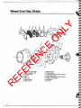
SECTION 2 - Planetary Wheel End. Wheel End Brakes. Axle Shaft.
Sleering Knuckle. Steering Cylinder. and Tie Rod
Illustrations
3.650 Drive Flange .......................... . ..... . . . ...... .. ... .. ... .. ...... . .................... . ... . .......7
Wheel End 3.650 Reduction ...................•••. . ..........•... . . •• • .•. ........ . ....• •• •• .. .•.. .. •... . . ..... 8
Wet Disc Brake Wheel End 3.650 Reduction ......... .. ................. __ .. .. ... . ......... . .... .. ......... .. ... .9
Tie Rod and Steering Cylinder Mounting . . ..... .. .. .. ...... . .. . .. . .... . .. ....... .... .. ... ....... .. .. . .......... .10
Axle Steering Joints ...... . . . . . ....................................... . .. . . ... . ......... . . . ... . ................ 11
Wheel End Disc Brake .. ........ .. .... .. .. ... .. ..... ...... . .
12
Removal of Planetary Drive Flange Assembly ..... . ...... . .. ............... . .. . .... . ........... .. ......... .... .....13
Disassembly of 3.650 Drive Flange .............. . .............. . . ... . . .................... ... . . . ........ ........ .14
Disassembly of Wheel End Hub ... . ....... . .......... .. . • • .• •••...... . .... . . • .•• .• • ........ . ...•••• • • • •• • • •. ..... 15
Disassembly of Wet Disc Brake Wheel End ....... . ....... .. . ...................... . ..... . ....... ........... ... . ...16
Removal and Disassembly of Spindle and Axle Shaft. ... . ... ...... . . ... . ...... . .... .. ................. .. ............19
Removal of Steering Cylinder and Tie Rod Assemblies ...... ... .. .... . .. .. ... . ........ ..... ..... . ..... ...... . .. .... .20
Disassembly of Steering Knuckles .... . .... . ....... . .. . ... .•. •• •. . • ... .. . ..... . .••• •••..... . .. . .. . .... • .•.•• .. ... .21
Assembly of Steering Knuckles ....................................... .. .........................................23
Installation ofTie Rod and Steering Cylinder Assemblies ... ........ . .. .. . . ....... . ... .. .... .. .... ... . . .. ...... .. . ... 24
Assembly and Installation of Axle Shaft and Spindle ..................•.••••••...........•••• • •• ... . ................25
Assembly of Wheel End Hub .......... . ... . . . ....... . . . .......... .... . .. .. ..... . . . . .. .. . . .. .. ... . . . ..... ... . ... .27
Assembly of Wet Disc Brake Wheel End.... . .. . ... . .. .. .. . . .. .... . .. ... ..... . ... ... ..... . .. .. .. .. . ..... . . . .. . ..... 28
Assembly of 3.650 Drive Flange ..........................• .• •• • •................ • • • ••.• ......... .. ... . . . .• • ......31
Steering Cylinder Disassembly and Assembly . .... .. ... . ....... .... ... .... .. .. . . .. . . . ... ... ... .. ..... . .... ... . .. ...32
Disassembly and Assembly of Wheel End Disc Brake ... ...... . .......•• • .•• .•• ... . .... . ....•• • •....................34
SECTION 3 - Carrier Assembly. Limited Slip Differenlial Option.
Pinion Mounted Dry Disc Parking Brake Option
Illustration
...
o'
. . . . . . . . .
...
.....
..
..
...
....
.
. . . . . . . .
.
o'
...
Carrier Assembly ....................... .. ... . ................... . ...... .. ............. .. .... . .... . ....... ... 38
Removal of Carrier From Axle Housing .. . . . ..... . .... . . ... . . . . . ..... .. ... .... ... . . .... . .. ... ..... . .. .. . ... . . . . ....39
Removal of Differential From Carrier ........ . ..••.. . .......... . ... . .... • • • . • . .. . ..... .. . • .•• .. •.. .. ...... . ....... .40
Differential Disassembly .................. . ..... . ..... . . . .... . .... . .................... ... ........ .. ....... . .. .. .41
Pinion Disassembly ................... .... .. ... ... .. .. . ... ...... .. . .... . ...... .. ..... .... ..... ..... .. .... . ... .. 43
Differential Assembly . ... . ............... . ....• •• .............. .. .....•.•• • • •...........••••................... .44
Pinion Position and Assembly ..................• . ...... ... . . ... . .......•••• • .••. .... ...•••.•••............. .. ... .46
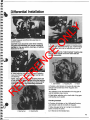
Differential Installation ....... . ................ . ......... ... ..... .. ..... . .... .... ... ... . .... ... ..................49
Ring Gear and Pinion Toolh Contact Pattern . ... ... . . .. .... ........ .. ... . .... ... .. .. . ... .. .... .. .. ...... .. ... .. . . .. 50
Installation of Carrier Assembly Into Axle Housing ..... . . ... . .. . .. . .. . ....... .. .. .. . .. . ..... .. .. . . ... . ......... . . . . .53
Pinion Mounted Dry Disc Parking Brake ..................... . ............................................ .. .......53
Parking Brake - Removal/Installation ................•..... .. .... . .. . ..... • .• • • •• . . ..........••.•• . •••. . . . .... .. . .54
Parking Brake - Disassembly/Assembly ... . .... . ..... ... ............ . ....... .. . . . . ...... .... .. .. ... . .. . . .. .. .. ... 55
Parking Brake - BleedinglTrouble Shooting .... . ••• . ............ . ..........• • •• • ........ . ... . • •• ............... . .. 56
Inspection and Failure Analysis ... . ..... . . . . . . .... .... . .... . . ..... ..... ... .. . ... ......... .... . ... . . .. .. . ... .... . .57
SECTION 4 - Specifications
Spicer Axle Lubricant Recommendations . . ... . .... .. ....... .. .... ... . . ..... ... ....... . .. . ... .. .. .. . . ........ . .. ... 59
Fastener Strength Identification .... . .... . ...... . .. .... ........... .. .. . . .. .. ... ............. . ........ ...... ... . .. .60
Wrench Tightening Torque Specifications .......... . ..................... .. ..... .. . ........... ... ........... . ......60
Bearing Preload Specifications . ... .... . .... .. ... . ••. .... .. ... .... . .... . ... • . • •• .. .........•• • •• •. . ••.• . • . ........ 60
Drive Pinion Ring Gear Backlash Specification .....• • • ••......... . . . .......... .• •• . ............ • , ••••••• • • • • .......60
EF
~
..
ER
EN
C
o'
""
~
~
R
~
~
'"
'~"
' "
~
~o'
•
1
SECTION 1
GENERAL INFORMATION
LY
IMPORTANT SAFETY NOTICE
-
ER
EN
C
E
O
N
Should an axle assembly require component parts replacement, it is recommended that "Original Equipment"
replacement parts be used. They may be obtained through your local service dealer or other original equipment
manufacturer parts supplier. CAUTION: THE USE OF NON-ORIGINAL EQUIPMENT REPLACEMENT PARTS IS
NOT RECOMMENDED AS THEIR USE MAY CAUSE ·UNIT FAILURE AND/OR AFFECT VEHICLE SAFETY.
Proper service and repair is important to the safe, reliable operation of all motor vehicles or driving axles whether
they be front or rear. The service procedures recommended and described in this service manual are effective
methods for performing service operations. Some of these service operations require the use of tools specially
designed for the purpose. The special tool should be used when and as recommended.
CAUTION: EXTREME CARE SHOULD BE EXERCISED WHEN WORKING ON COMPONENTS UTILIZING
SNAP RINGS OR SPRING LOADED RETENTION DEVICES. FOR PERSONAL SAFETY, IT IS RECOMMENDED
THAT INDUSTRIAL STRENGTH SAFETY GOGGLES OR GLASSES BE WORN WHENEVER REPAIR WORK
IS BEING DONE ON ANY VEHICLE OR VEHICLE COMPONENTS.
It is impossible to know, evaluate and advise the service trade of all conceivable ways in which service might be
done or of the possible hazardous consequences of each way. Accordingly, anyone who uses a service procedure
or tool which is not recommended must first satisfy himself thoroughly that neither his safety or vehicle safety will
be jeopardized by the service methods he selects.
- - - - - - - -- - WARNING - - - - -- - - --
Some vehicle manufacturers may require the assembly of brake components on Dana axles that utlfize
materials containing asbestos fibers.
BREATHING ASBESTOS DUST MAY BE HAZARDOUS TO YOUR HEALTH AND MAY CAUSE SERIOUS
RESPIRATORY OR OTHER BODILY HARM.
Follow O.S.H.A. standards for proper protective devices to be used when working with asbestos materials.
SILICONE RUBBER SEALANT (RTVl AND LUBRICATING GREASE AND OILS
Silicone rubber sealant is used as a gasket material on some Dana axles, as well as various lubricants and
other materials. Before using any of these materials, one should become familiar with and follow all safety
precautions as recommended by the product manufacturer/supplier. All personnel involved with these
materials should follow good industrial hygiene practices (e.g. before eating, hand and face should be
thoroughly washed. Eating, drinking and smoking should be prohibited in areas where there is potential
for significant exposure to these materials~
EF
When discarding any of the materials, observe all local, state, and federal laws and regulations for proper
disposal procedures.
R
Safety Precautions
2
A
ThiS symbol warns of possible personal
Injury.
A
A serious or fatal injury can occur . . .
if you lack proper training
• if you fail to follow proper procedures
• if you do not use proper tools and
safety equipment
.
• if you assemble components
improperly
• if you use incompatible components
• if you use worn-out or damaged
components
• if you use components in a nonapproved application
A
SAFETY GLASSES SHOULD BE WORN
AT ALL TIMES WHEN WORKING ON
VEHICLES OR VEHICLE
COMPONENTS.
f
4
4
C
~ -----------------
Axle Identification
0
PLYMOUTH, MINNESOTA
U.S.A.
SPICER
I 070BPOOO-0 IIPIN I
I 7036-oooooo=:] ~
'"
I
12-12-88
IIDATEI
L-______-====~==--.t. 0
Gear Set Identification
ER
EN
C
Manufacturer's date-date gear set was made.
Dana-Dana name-and location of manufacturing.
572199C91-part number of ring gear.
(Typical)
Tooth combination (i.e. 37-6}-indicates the pinion
has 6 teeth and the ring gear 37 teeth which results in
a 6.17:1 ratio.
Matched set number-8picer ring and pinions are
manufactured as a matched set. Both pieces are
marked with a corresponding number (Le. 268) which
indentifies them as a matched set.
A gear set that does not have the same matching
numbers should not be run together. If either a ring
gear or pinion require replacement they must be
replaced as a matched set.
O
N
o
The identification tag located on the rear of the axle
housing contains the axle assembly number, the serial
\ number and the build date. It is recommended when
' referring to components of Ihe axle assembly that all
the information recorded on this tag be obtained to aid
in the correct identification.
LY
~------------~
E
o
PART
EF
NUMBER
R
MFG.
If/!
•
BACKLASH
ETCHED
3
Servicing Components Not Covered In This Manual
Service procedures for some components may not be covered in this manual because they are unique to the
vehicle application. Refer to the vehicle manufacturer's service manual for servicing those components.
LY
Vehicle Storage Or Prolonged Inoperation
O
N
If the vehicle has not been operated on a regular daily basis, it is recommended that the vehicle be operated at
least once every two weeks. The vehicle should be moved far enough to cause the drivetrain components to make
several complete revolutions. This procedure will help assure that all internal components receive adequate
amount of lubrication to help reduce component deterioration caused by an undesirable environment (e.g. high
humidity).
Submersion Or Deep Water Fording
ER
EN
C
E
If the vehicle is exposed to water deep enough to cover the hubs, it is recommended that the wheel ends be
disassembled and inspected for water damage and/or contamination.
In the event the carrier housing should become submerged in water, particularly if over the breather, it is
recommended that the hypoid gear lubricant be drained and internal parts be inspected for water damage and/or
contamination.
Clean, examine, and replace damaged parts if necessary, prior to assembling and refilling with the specified
lubricants.
NOTE: If the hubs are exposed to deep water, It is possible on steering axles that the water could enter the
carrier at the point the inner axle shaft enters the axle housing. This could also necessitate the draining of
the hypoid lubricant as described above.
It is recommended that whenever bearings are removed, they be replaced with new ones, regardless of
mileage.
Axle Lubricant Change Schedule
The following schedule is a suggested lubricant change schedule. Lubricant in your vehicle may require more
frequent changes depending on the environment in which it is operated. Contact your local authorized service
dealer or refer to your owner's manual for obtaining the proper lubricant change schedule for your vehicle.
EF
BREAK IN
After 100 hours of operation, Ihe lubricant should be
drained and replaced with fresh lubricant to the
correct level and of the type specified.
R
SERVICE
It is recommended that the lubricant be changed at
2000 hours of operation. When yearly usage is less
than 4000 hours, the lubricant should be changed
twice yearly.
4
AFTER OVERHAUL
When refilling the axle assembly or planetary hub
assembly after it has been disassembled for service,
the lubricant should be filled to the bottom of the fill
hole located in the bowl of the axle housing or the
planetary drive flange. After 24 hours of operation
recheck the lubricant level and bring it up to the
bottom of the fill hole again, if necessary. This
procedure is recommended to replenish the small
amount of lubricant that is retained in the differential
support case or planetary gearing during initial
operation of the axle immediately following an
overhaul.
General Precautions for Assembly and
Disassembly
A
O
N
BEARINGS
Use suitable pullers for bearing removal. Clean,
inspect, and lubricate all'bearings just prior to
reassembly.
ER
EN
C
NOTE: The photos or pictures contained herein are
for illustrative and instructional purposes only. The
appearance of your axle assembly and/or
components may vary from that shown. However,
the service procedures described will apply.
If it becomes necessary to disassemble any parts
inside the carrier, it is suggested that the entire axle
be removed from the vehicle and held tight in a
stand or rack.
All dimensions are in inches unless otherwise
stated.
END YOKES AND FLANGES
CAUTION: Hammering on end yokes or flanges to
remove or install them is not only destructive to
the yoke or flange itself, but can also cause
serious internal damage. Hammering on end
yokes can close in the bearing bores or misalign
yoke lugs and result in early failures of journal
needle bearings or other drivellne components.
Serious damage can also be done internally to the
ring and pinion set or pinion bearings by
hammering on external parts. End yokes or
flanges should be removed or installed using a
recommended method such as that described
herein.
E
USE ONLY GENUINE REPLACEMENT PARTS FOR
SATISFACTORY SERVICE.
LY
IMPORTANT
READ THIS SECTION BEFORE STARTING THE
DETAILED ASSEMBLY OR DISASSEMBLY
PROCEDURES.
WARNING: When removing axle assembly,
make sure vehicle is properly supported.
Improperly supported vehicle can cause
serious injury or death. Follow vehicle
manufacturers recommendations for proper
axle assembly removal procedures.
EF
Safety Glasses should be worn
at all times when
assembling or disassembling.
R
CLEANLINESS
The axle assembly should be steam cleaned prior to
disassembly. Seal all openings before steam cleaning
to prevent entry of dirt and water which can damage
serviceable parts.
Thoroughly clean all parts just prior to assembly.
REBUILD FACILITIES
If the axle assembly is removed from the vehicle, it
must be safely supported at three points on the
housing. If the axle is to remain in the vehicle, use the
OEM recommended support method.
A suitable holding fixture should be used rebuilding
the carrier assembly. A lifting device should be used to
relocate the carrier assembly and to install or remove
the ring gear and support case assembly.
NOTE: It is recommended that whenever bearings
are removed, they are (regardless of mileage) to
be replaced with new ones.
NOTE: If replacement of a damaged bearing cup or
cone is necessary, the cup and cone must be
replaced as a set.
OIL OR GREASE SEALS
Whenever it becomes necessary to remove an oil or
grease seal to gain access to an adjacent component
for replacement or repair, that seal is to be discarded
because of possible damage.
CLEANING
Parts with machined or ground surfaces such as
gears, bearings, and shafts should be cleaned with
emulsion cleaners or petroleum based cleaners.
Steam cleaning of internal components and the
interior of the planetary hub and axle housing is not
recommended. Water can cause corrosion of critical
parts. Rust contamination in the lubricant can cause
gear and bearing failure.
Clean all surfaces of old gasket malerial.
DRYING
Use clean lintless towels to dry components after
cleaning . DO NOT dry bearings by spinning with
compressed air. This can damage mating surfaces
due to lack of lubrication.
5
After drying, components should be lightly coated with
oil or rust preventive to protect them from corrosion. If
components are to be stored for a prolonged period
they shou ld be wrapped in wax paper.
• Worn or scored planet gear or differential pinion
gear shafts.
• Axle shafts or worn splines, bends, cracks, or for
torsional fractures or other indications of
impending failure.
INSPECTION
• BOLTS: Make sure all bolts are torqued to the
recommended specifications.
LY
• LUBRICATION: Coat bearings, seals, and splines
with lubricant to provide initial lubrication and prevent
damage during assembly.
• BEARINGS: Bearing drivers which apply equal
forces to both races of the bearing are recommended.
If another type of driver is used, it is important that the
driving force not be transmitted through the rollers.
O
N
Prior to reassembly, inspect parts for signs of wear
or damage.
Bearing surfaces should be inspected for pitting, wear,
or overheating.
Inspect, all bearings, cups, and cones, and replace if
worn, pitted or damaged. When replacing bearings,
use a suitable puller or pressing fixture to remove
them. Avoid using drifts and hammers which may
mutilate or distort component parts.
Inspect planetary and carrier components for wear or
damage. Replace if the following conditions are found.
• Worn, chipped , pitted or scored gears.
• Worn, pitted, or scored thrust washers.
USE A PRESS WHERE POSSIBLE WHEN
ASSEMBLING COMPONENT PARTS WHICH
REQUIRE AN INTERFERENCE FIT.
R
EF
ER
EN
C
E
Dana Corporation, Spicer Off- Highway Axle
Division, reserves the right to make changes from
time to time, without notice or obligations, in
specifications, descriptions, and illustrations, and
to discontinue models or revise designs_
6
~-----------------------------------------------
SECTION 2
R
EF
ER
EN
C
E
O
N
LY
Planetary Wheel End, Wheel End Brakes,
Axle Shaft, Steering Knuckle Steering Cylinder,
Tie Rod
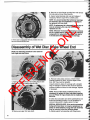
3.650 Drive Flange
1
2
3
4
5
6
7
8
9
10
11
12
Caps crew-Self Locking Flange Mounting
Pipe Plug or Vent
Recessed Drive Pipe Plug (Magnetic)
Planetary Drive Flange
Planetary Gear Shaft
Roll Pin
Drive Flange Washer (Thrust Washer)
Flat Spacer (Thrust Washer)
Needle Roller Bearing
Spacer Ring-Bearing
Planetary Spur Gear
Plate-Lining Stop (Wheel End Wet Disc Brake Use
Only)
7
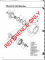
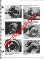
Wheel End 3.65 Reduction
EF
ER
EN
C
E
O
N
LY
16
R
6
4
1
1
2
3
4
5
6
7
8
9
10
11
12
13
14
15
16
17
18
8
Snap Ring
Sun Spur Gear
Flat Spacer
Planetary Ring Gear
Roll Pin
Lock Nut
Bearing Cone (Outer)
Bearing Cup (Outer)
Wheel Mounting Nut
Planetary Hub
Wheel Mounting Bolt
Bearing Cup (Inner)
Hub Slinger (For Axles Without
Wheel End Brakes Only)
Bearing Cone Inner
Oil Seaf-Hub
Spindle
Bushing-Outer Shaft
Oil Seaf-Outer Shaft
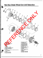
Wet Disc Brake Wheel End 3.65 Reduction
25
24
LY
j
22
O
N
/'
ER
EN
C
E
16
EF
14
Snap Ring
Sun Spur Gear
Disc Assembly-Friction
Plate-Stalionary
Piston
O-Ring
O-Ring
Capscrew-12 Point
Retainer-Bearing Adjusting
Tube-Brake Bleeding
O-Ring
Shim-Adjusling (.010, .011, .012, .013, .014, .015,
.020, .030 Thick)
O-Ring
Planetary Ring Gear
Bearing Cone (Outer)
R
1
2
3
4
5
6
7
8
9
10
11
12
13
14
15
16
17
16
19
20
21
22
23
24
25
26
27
26
29
30
Bearing Cup (Outer)
Planetary Hub
Wheel Mounting Nut
Wheel Mounting Bolt
Bearing Cup (Inner)
Bearing Cone (Inner)
Oil Seaf-Hub
Deflector-Hub Oil Seal
Fitting Brake Inlet
Spindle
Guard-Fitting/Bleeder
Seat-Insert
Bleeder
Bushing-Outer Shaft
Oil Seat--Outer Shaft
1
9
>
R
EF
ER
EN
C
E
O
N
LY
Tie Rod & Steering Cylinder Mounting
10
1
2
3
4
5
6
7
8
TIe Rod Assembly (Items 2 Ihru 5)
TIe Rod
Vertical Socket Assembly
Clamp Assembly-Tie Rod
Vertical Socket Assembly
Steer CylinderNertical Socket Assembly (Items 7 and 8)
Vertical Socket Assembly
Steer Cylinder
Axle Steering Joints
0-
21
9-
23
O
N
ER
EN
C
23-@
22_Q
E
24--Q
LY
~-22
21-C)
~
~
~
i!!f
""
~
EF
~
fi!I
iif
~
iii
~
i!I
".~
~
"
~
if
1 Rigid Axle Sha~ or Shaft
and Joint Assembly
(Includes items 2 thru 6, 7 or 8)
2 Sha~-Outer Yoke
3 Cross Assembly
4 Bearing Race Assembly
5 Snap Ring
6 Center Yoke
7 Sha~-Inner Yoke (Short)
8 Sha~-Inner Yoke (Long)
9 Deflector-Inner Shaft Seals
10 Oil Seal-Inner Shaft
11 Bushing-Inner Sha~
12 Steering Knuckle
R
if
:!if
.,
I
2
•
13 Stud-Spindle Mounting, Steer Axle
14 Locknut-Spindle Mounting
15 Washer-Aat
16 Fitting-Grease
17
18
19
20
21
22
23
24
25
Capscrew-King Pin Cap Mounting
Washer-Flat
Cap-King Pin
Shim--King Pin Bearing Adjusting
Seal-King Pin Bearing
Bearing Con<>-King Pin
Bearing Cup-King Pin
Retainer-Grease
Stud-Spindle Mounting, Rigid Axle
11
O
N
LY
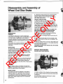
Wheel End Disc Brake
ER
EN
C
E
10
11
/
12
13
~j
16
Brake Lining (Outer Pad)
Brake Lining (Inner Pad)
Dust Boot Shield
Dust Boot
Piston
Piston Seal
Caliper Housing
Bleeder Screw
R
EF
1
2
3
4
5
6
7
8
12
9 Bleeder Screw
10 Caliper Bracket
11 Compression Spring (Caliper Support)
12 Caliper Support Key
13 Socket Head Screw (Caliper Support)
14 Hydraulic Fluid Fitling
15 Disc (Rotor)
16 Hex Bolt
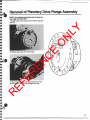
Removal of Planetary Drive Flange Assembly
O
N
LY
NOTE: The following procedures are the same for
both rigid and steer axles.
1. Rotate hub 50 drain plug is down. Remove plug and
drain oil.
~
2. Remove"capscrews from drive flange.
E
F'>
,"
0~
%0
~
>-
28
-(
ER
EN
C
J
.(
~
r~
"<
"r
R
EF
3. Tap drive Ilange with soli faced hammer to break
loose from hub. Remove drive flange from hub.
13
O
N
LY
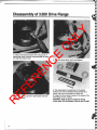
Disassembly of 3.650 Drive Flange
E
1. Using a hammer and punch, drive roll pins out of
planet gear shafts. Remove lining stop plate for wheel
end wet disc brake if used.
EF
ER
EN
C
3. Remove planet gears and thrust washers.
2. Insert pry bar into groove in planet gear shaft and
R
remove gear shaft.
14
4. The planet gears are supported on the planet
shafts by two rows of needle bearings divided by a
spacer ring and a thrust washer on each end.
5. Inspect the thrust button located in the center of the
drive flange . If worn, replace.
WARNING: Keep the groove under the thrust
button open. It is the access to the air vent If used.
Disassembly of Wheel End Hub
LY
NOTE: the following procedure is the same for
both rigid and steer axles.
E
ER
EN
C
1. Insert small screwdriver under end and remove
locking ring from end of axle shaft by rotating around
shafl.
O
N
4. Remove the wheel bearing adjusting nut using a
three pin spanner wrench. (Dana tool #451125)
NOTE: If axle Is equipped with wheel and disc
brakes, remove the caliper assembly at this time
as outlined in the disc brake section of this
manual.
5. Remove the outer wheel bearing while supporting
the hub assembly.
R
EF
2. Remove sun gear and spacer from axle shafl.
3. Remove ring gear. Use a suitable puller if necessary.
NOTE: DO NOT pilot puller on axle shaft. This may
damage the Inboard axle seal.
6. With the hub supported, carefully remove it from the
spindle.
NOTE: A lifting device is recommended for
assemblies having a rotor attached.
15
8. Rest hub on drive flange mounting face and remove
the hub seal and inner wheel bearing.
9. Inspect wheel bearings and cups and replace .if
necessary. Remove cups with a suitable puller.
NOTE: It is recommended that whenever bearings
are removed, they are (regardless of mileage) to
be replaced with new one~
LY
NOTE: If replacement of a damaged bearing cup or
cone is necessary, the cup and cone must be
replaced as a set.
O
N
NOTE: Whenever It becomes necessary to remove
an oil or grease seal to gain access to an adjacent
component for replacement or repair, that seal is
to be discarded because of possible damage.
7. If the axle is equipped with disc brakes the rotor
can be removed at this time.
ER
EN
C
NOTE: the following procedure is the same for
both rigid and steer axles.
E
Disassembly of Wet Disc Brake Wheel End
R
EF
1. Insert small screwdriver under locking ring on axle
shaft and remove by rotating around shaft.
2. Remove sun gear from axle shaft.
16
3. Remove brake plates and discs. Check friction
material thickness on discs. If groove depth is less
than .005" they must be replaced.
Inspect stationary plates for warpage with a straight
edge. If warpage is observed they must be replaced.
Inspect all plates and discs for heat damage. Replace
if necessary.
NOTE: If any of the above conditions exist it is
necessary to replace all discs and plates together
as a set. Piston O-rings should also be replaced at
this time.
If brake discs and plates are within specifications and
brake was operating properly it is not necessary to
remove brake piston or replace piston O-rings.
SPECIAL SERVICE NOTE: If the service procedure
being performed does not require replacement of
piston or wheel retainer O-rings the hub assembly
may be removed using the following steps.
A. Safely support hub assembly with lifting device.
B. Remove wheel retainer cap·screws.
O
N
LY
E. Skip following steps #4 thru #9. Continue
disassembly with step #10.
ER
EN
C
E
4. Remove brake piston from wheel end.
NOTE: Use of a special piston remover/installer
tool, (Dana tool #451164), is recommended to
prevent damage to the piston.
C. Remove planetary ring gear, brake piston and
wheel retainer as one unit.
R
EF
SA. Remove outer diameter piston O·ring. Discard and
replace with new.
D. Remove oil passage O·rings from grooves on
inboard face of wheel retainer. If damaged, replace. If
ok, save for re·assembly.
5B. Remove inner diameter piston O-ring. Discard and
replace with new.
\
17
LY
O
N
9. Remove planetary ring gear from wheel end.
Inspect outboard wheel bearing. Replace if necessary.
10. With hub supported. carefully remove it from
the spindle.
ER
EN
C
E
6. Safely support hub assembly with a lifting device.
Remove wheel retainer capscrews. Remove wheel
retainer and preload shims. Wire shims to retainer to
facilitate re-assembly.
R
EF
7. Remove oil passage O-rings from groove on
inboard face of wheel retainer. If damaged. replace, If
ok, save for re-assembly.
8. Remove and inspect ouler diameter O-ring on
inboard side of wheel retainer. Replace if necessary.
t8
11. Inspect wheel bearings, cups and seal. Replace
if necessary.
NOTE: It Is recommended that whenever bearings
are removed, they are (regardless of mileage) to
be replaced with new ones.
NOTE: If replacement of a damaged bearing cup or
cone is necessary, the cup and cone must be
replaced as a set.
NOTE: Whenever it becomes necessary to remove
an 011 or grease seal to gain access to an adjacent
component for replacement or repair, that seal Is
to be discarded because of possible damage.
3. The spindle in many applications, contains an outer
shaft oil seal and bronze bushing in the spindle bore.
These should be replaced if necessary.
E
lA. Remove spindle mounting nuts and flat washers.
On planetary equipped with disc brake, the caliper
mounting bracket can be removed when the spindle
mounting nuts are removed.
O
N
LY
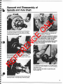
Removal and Disassembly of
Spindle and Axle Shaft
ER
EN
C
NOTE: Whenever it becomes necessary to remove
an oil or grease seal to gain access to an adjacent
component for replacement or repair, that seal is
to be discarded because of possible damage.
NOTE: Inspect the spindle mounting studs in steer
knuckle or axle housing (rigid axle) for damage
and replace if necessary.
R
EF
lB. On planetary equipped with wet disc brake wheel
ends remove brake inlet fitting and bleeder screw.
Remove spindle mounting nuts, washers, and (if used)
the fitting/bleeder guards.
4. To remove axle shaft assembly on the steering axle,
hold shaft level and pull straight out to avoid damaging
inner shaft oil seal.
NOTE: To remove axle shaft on rigid axles, pull
shaft straight out.
2. Tap spindle with soft faced hammer to loosen from
steering knuckle or housing flange. Remove spindle.
19
LY
O
N
5. To separate inner and outer axle shafts, on steering
axle, first remove all bearing cap retaining rings.
6. Next, press out u-joint bearing caps and remove
cross.
7. Inspect u-joint bearing caps and cross and replace
if necessary.
ER
EN
C
E
Removal of Steering Cylinder
and Tie Rod Assemblies
EF
1. Disconnect the hydraulic hoses to the steering
cylinders. Plug the open fittings.
R
2. Remove the cotter pins from the steering cylinder
socket assemblies.
3. Remove the slotted hex nuts that fasten the cylinder
socket assemblies to the anchor points on the carrier
and steering knuckle. Tap the threaded end of socket
assembly lightly with a soli faced hammer to unseat
them . Carefully remove steering cylinder assemblies.
Mark cylinder assemblies "rightside" "Iellside" to aid
reassembly.
CAUTION: Protect chrome finish on rod at all
times. Damage to surface of rod can cause
premature seal failure.
NOTE: Refer to steering cylinder disassembly and
assembly section of manual if further disassembly
of cylinder assembly is required.
\
20
LY
O
N
5. Remove the slotted hex nuts that fasten the tie rod
socket assemblies to the steering knuckle anchor
points. Tap the threaded end of the socket assembly
lightly with a soft faced hammer to unseat them.
Remove the tie rod assembly. Match marked tie rod
end and steering knuckle to aid in reassembly.
NOTE: Do not alter the tie rod adjustment unless
further repair is required to tie rod components.
If repair is required or tie rod adjustment is
inadvertently changed it will require the resetting
of this adjustment for proper "toe-in".
ER
EN
C
E
4. Remove the cotter pins from the tie rod socket
assemblies.
Disassembly of Steering Knuckles
R
EF
1. Remove the wheel end components, spindle. axle
shaft, steer cylinder, and tie rod prior to disassembly of
steer knuckle components.
2. Remove bearing cap bolts and washers from both
upper and lower bearing caps.
.~
3. Remove both upper and lower bearing caps and
shims. Wire shims together with their respective
bearing caps to facilitate reassembly.
•
21
LY
O
N
ER
EN
C
E
4. Tip the steering knuckle slightly and remove from
housing yoke.
6. Inspect axle seal and bushing. If replacement is
necessary, remove with suitable puller.
7. Inspect bearing cup and seal; replace if necessary.
NOTE: It Is recommended that whenever bearings
are removed. they are (regardless of mileage) to
be replaced with new ones.
R
EF
5. Inspect bearing cone and replace if necessary.
22
NOTE: If replacement of a damaged bearing cup or
cone Is necessary. the cup and cone must be
replaced as a set.
NOTE: Whenever It becomes necessary to remove
an oil or grease seal to gain access to an adjacent
component for replacement or repair, that seal is
to be discarded because of possible damage.
Assembly of Steering Knuckles
O
N
LY
1. Install inner axle shalt bushing and seal into
housing yoke bore.
2. Apply #2 Permatex to grease retainers. Install
grease retainers and king pin bearing cups into
housing yoke.
NOTE: The grease retainer must be installed with
Its "dished" portion positioned toward the inside
of the axle housing yoke. Installed opposite, the
retainer would restrict the bearing cup from
seating properly in the housing bore and clamp
against the bearing cone cage restricting
movement.
ER
EN
C
E
6. Place original shims in position on knuckle or king
pin cap.
7. Install bearing caps, washers, and bolts. Torque to
80-90 It. Ibs.
R
EF
3. Install pregreased king pin bearing cones into
bearing cups.
4. Install king pin seals.
NOTE : Inspect the spindle mounting studs in steer
knuckle for damage and replace if necessary.
5. Place knuckle in position over housing yoke.
8. To check king pin bearing preload, turn knuckle all
the way to the right. Place torque wrench on one 01
the king pin cap bolts. Rotate knuckle through
complete turn angle. Torque reading should be 8-15 ft.
Ibs. Measurement is made less hub components, axle
shaft, tie rod, and steering cylinder.
To increase preload, remove shims lrom top or bottom
king pin bearing. To decrease preload, add shims to
top or bottom king pin bearing . Keep top and bottom
shim packs as equal as possible.
23
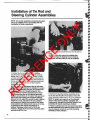
Installation of Tie Rod and
Steering Cylinder Assemblies
E
O
N
LY
NOTE: The carrier assembly and steering knuckles
are to be installed prior to proceeding with the
installation of these components.
ER
EN
C
2. Install cotter pins and bend the pin over to lock it in
place.
NOTE: If cotter pin cannot be installed after
minimum torque is attained, the nut must be
advanced until the cotter pin can be installed.
R
EF
1. Connect the tie rod assembly to the steering
knuckle anchor points. Torque the socket assembly
slotted nuts to 140 It. Ibs. minimum. Check to make
sure the position 01 the offset in lhe tie rod clears the
carrier assembly in lull turn posiition (both directions).
The tie rod assembly should be switched around end
lor end il lull turn clearance is not lound and the
slotted nuts retorqued.
NOTE: If the tie rod adjustment (toe-In) has been
changed it will be necessary to readjust it. Loosen
tie rod clamp assembly bolt and nut. Position the
steering knuckles in a straight ahead (0· turn
angle) position. Position measuring bars on the
spindle mounting face of the steering knuckles.
Measure across them on the carrier side and cover
side of the axle housing and compare readings.
Remove tie rod, adjust the overall socket to socket
length (in or out1 reinstall the tie rod assembly
and remeasure. Repeat this procedure until equal
measurements are attained (zero toe-In) or the toein specified by the vehicle manufacturer is
attained. Retorque slotted nuts to 140 ft. Ibs.
minimum. Torque the tie rod clamp assembly bolts
and nuts to 60-70 ft. Ibs.
24
3. Connect the steering cylinder assemblies to the
carrier and steer knuckle anchor points. Torque the
socket assembly slotted nuts to 140 It. Ibs. minimum.
NOTE: If repairs were made to or the retracted
length of the steering cylinder assembly was
inadvertently changed the retracted length of the
assembly will require resetting as follows:
A. Remove slotted nuts from and remove rod end
socket assemblies from steer knuckles. Push In or
use air pressure retract the rod into the barrel
assembly of both cylinders.
•
B. Turn steering knuckle to full Inside turn
position on either the right or left hand side.
LY
C. Adjust the socket assembly position In or out
. on the rod end and also barrell end, if required,
such that Its retracted length matches the length
required for assembly to its steer knuckle.
CAUTION: Protect the rod from damage while
adjusting socket position.
Reconnect the cylinder assembly as noted In step
#3. Torque the cylinder socket clamp bolts and
nuts to 60-70 ft. Ibs.
O
N
D. Turn the other steer knuckle to its full inside
turn position. Adjust its steer cylinder retracted
length as noted In step C.
E
4. Install cotter pins and bend the pin over to lock it in
place.
NOTE: If cotter pin cannot be installed after
minimum torque is attained, the nut must be
advanced until the cotter pin can be installed.
5. Connect the hydraulic hoses to the steering
cylinders and "bleed" the system.
EF
ER
EN
C
Assembly and Installation of
Axle Shaft and Spindle
R
1. To assemble inner and outer axle shafts, insert
u-joint cross into yoke of outer shaft and press in
bearing caps. Repeat wilh center yoke and inner shaft.
3. Support shaft assembly and slide into axle housing
and engage in differential side gear. Care should be
taken when installing shaft as not to damage axle
shaft oil seal.
NOTE: On rigid axles, install the axle shaft Into the
axle housing until it engages the differential
side gear.
2. Install all bearing cap retaining rings. Grease u-joint.
25
LY
O
N
6A. On planetary equipped with disc brake, install the
caliper mounting braket on the mounting sluds. The
bracket is to be positioned such that when the brake
caliper assembly is installed it will be on the cover side
of the axle housing (3 or 9 o'clock position). Also, the
support key and spring leg of the bracket is to be on
the top side. Install the mounting washers and nuts
and torque to 80-100 ft. Ibs.
ER
EN
C
E
4. Install new bushing and seal in spindle if required.
5. Install spindle over the axle shaft and onto knuckle
or housing flange studs.
NOTE: Care should be taken when sliding the
spindle over the end 01 the axle shalt so as not to
damage the outer shalt seal and bushing il so
equipped.
R
EF
NOTE: On planetary equipped with wet disc brake
wheel ends the spindle is to be assembled to the
mounting studs with the brake bleeder port
positioned at the top (12 o'clock position) and the
brake inlet port on the carrier side 01 the axle
housing.
26
68. On planetary equipped with wet disc brake wheel
ends proceed as follows:
1) Install the fitting/bleeder guards, if used, on the
mounting studs. Guards are not to be installed in the
area between the bleeder and inlet ports but just
outside of that area and such that they will not
interfere with the installation of the bleeder screw and
inlet fitting.
2) Install the mounting washers and nuts and torque to
80-100 ft. Ibs.
3) Install the bleeder screw in the top port and tighten
until it is seated properly.
4) Install the brake inlet filting in the other port and
tighten until it is seated properly.
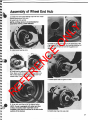
Assembly of Wheel End Hub
O
N
LY
1. Install inner and outer bearing cups into hub. Install
inboard bearing and hub seal.
2. Install hub onto spindle.
NOTE: A lilting device is recommended lor
assemblies having a rotor attached.
-..:--'-- .
ER
EN
C
3. Install outer bearing cone.
E
6. Install ring gear. The roll pin on the back face of the
ring gear must be locked into the bearing adjusting nu1
hole. Use punch mark on front of ring gear as an
alignment aid.
4. Install bearing adjusting nut. Torque to 200-250
fUbs. Back nut off 1/8 turn and align any hole in nut
with a major spline on the spindle. Make sure hub
rotates freely. (Use Dana Tool #451125)
R
EF
7. Install spacer and sun gear on shaft.
5. As an aid, mark the end of the aligned spline.
NOTE: " axle is equipped with wheel end disc
brakes, the brake caliper assembly can be
installed at this time as outlined in the disc brake
section 01 the manual.
8. Install snap ring onto axle shaft.
27
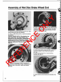
Assembly of Wet Disc Brake Wheel End
~ .>
....
.
LY
r;~ .
',)
.
",.
\
O
N
.'
... ~.~"t
1. Install inner and outer bearing cups into hub. Install
inboard bearing and seal and deflector.
"" __
.,>-._,
.,
B. Install ring gear/piston assembly onto spindle spline
making sure oil passage hole in ring gear is to bottom
of axle at 6 o'clock position. Mounting holes in wheel
retainer will align only one way.
ER
EN
C
E
2. Using a suitable lifting device. install hub assembly
onto spindle.
SPECIAL SERVICE NOTE: If the planetary ring
gear, brake piston, and wheel retainer were
removed as a unit, (described In disassembly
section~ and It was not necessary to replace
wheel bearings or cups, use the following lettered
steps for reassembly. Otherwise proceed with
steps #3.
C. Install wheel retainer capscrews with Loc!ite" 271
compound applied to the threads and torque to
45 ft. Ibs.
D. Skip following steps 3 thru 10 and continue
assembly with step 11.
EF
-~-~-
R
A. Insert both oil passage O-rings into grooves on
inboard face of wheel retainer using a small amount of
petroleum jelly to hold them in place and facilitate
assembly.
3. Install outboard wheel bearing onto planetary ring
gear.
28
LY
O
N
E
4. Install planetary ring gear onto spindle spline
making sure oil passage hole in ring gear is to bottom
of axle at 6 o'clock position.
ER
EN
C
7. Place original wheel pre-load shims onto inboard
side of wheel retainer and install into planetary ring
gear. Make sure bleeder tube in retainer is to top of
axle at 12 o'clock position.
R
EF
5. Lubricate and install outer diameter O-ring onto
groove around inboard side of wheel retainer.
6. Insert both oil passage O-rings into grooves on
inboard face of wheel retainer. Use a small amount of
petroleum jelly to hold them in place and facilitate
assembly.
8. Install wheel retainer capscrews with Loctite· 271
compound applied to the threads. Gradually increase
torque value on capscrews using a crossing pattern
until 45 ft. Ibs. is achieved on each capscrew.
NOTE: At this point check wheel bearing preload.
Torque to rotate wheel should be 50-80 in. Ibs.
when measured with a torque wrench from the
center of the hub. If a spring scale Is used, wrap a
cord around the wheel pilot diameter. Readings
taken with this method should be 10-15 Ibs. Pull
while the hub is rotating.
To increase preload add shims. To decrease preload
subtract shims.
29
LY
O
N
9. Lubricate and install outer and inner diameter
piston O-rings.
ER
EN
C
E
12. Install snap ring into groove on outboard end of
outer shaft.
13. Push inward on end of axle shaft to seat sun gear
against wheel retainer. This will prevent rotating disc
from dropping behind gear during installation.
R
EF
10. Install brake piston.
NOTE: Use of a special piston remover/installer
tool, (Dana tool #451164~ is recommended to
prevent damage to the piston.
11. Install sun gear onto outer axle shaft.
30
14. Install brake plates and discs into wheel end (4
each). Start with a steel stationary plate first, then a
grooved friction disc (shown) second. Alternate until 4
of each are in place.
NOTE: If new discs are installed, presoak in the
correct lubricant as recommended by the vehicle
manufacturer for a minimum of 15 minutes prior
to assembly.
Assembly of 3.650 Drive .Flange
E
5. Install planet gear shaft into drive flange. If
equipped with wet disc brakes install lining stop plate.
Align holes and install roll pins.
ER
EN
C
2. Grease inside of planet gear. Install two rows of
needle bearings (25 per row) separated by
spacer ring.
O
N
LY
1. Install thrust button and vent into drive flange.
R
EF
3. Place thrust washer onto drive flange.
6. Apply small bead of Permatex #2 gasket sealer
around drive flange.
NOTE: DO NOT use silicone sealer on drive flange.
It can cause flange to loosen.
4. Install planet gear and remaining thrust washer.
7. Align gears and install drive flange into hub. Rotate
hub to align bolt holes.
8. Install and torque bolts 90-100 ft. Ibs.
31
Steering Cylinder Disassembly and Assembly
ffi
6
5
I
I
-
,::;@g
-f;;ij) I
1m
4
~
\: i n
I
Piston
Gland
Rod
Barrel Assembly
Locknut
Wear Strip
7
8
9
10
11
12
Piston Seal
Rod Static Seal
Gland Static Seal
Lockwire
Rod Seal U-Cup
Rod Wiper
ER
EN
C
1
2
3
4
5
6
I
B
LY
,
3
9
O
N
10
E
2
NOTE: Prior to disassembly of steer cylinder
assembly loosen the socket assembly clamp bolt
and nut and remove the socket assemblies from
the steering cylinder.
t
4
4
4
4
I
C
•4
4
~
4
4
4
~
CAUTION: Protect chrome finish on rod at ali
times. Damage to surface of rod can cause
premature seal failure.
EF
DISASSEMBLY
R
1. A sharp objecl, such as a screwdriver, must be
used to get under the lockwire to starl it out of
the cylinder.
NOTE: Direction of rotation for lockwire removal
depends on prior installation. Check lockwire
position for correct rotation.
2. Locate spanner wrench in drilled holes in gland and
rotate 360' in proper direction to remove lockwire.
32
(
(
3. Pull on the rod to remove the piston and gland.
4. Remove the nut from the end of the rod.
5. When the cylinder is disassembled, all seals should
be replaced before reassembling.
CLEANING AND INSPECTION
1. Check rod and cylinder bore for nicks, burrs,
scratches or rust. Slight defects may be removed with
fine sand paper.
2. All parts removed from the cylinder that are to be
reused should be thoroughly cleaned. Be sure to
carefully clean all cavities and grooves prior to
replacing parts.
•
~
ASSEMBLY
1. Install all seals. Do not over stretch seals to
facilitate easier installation.
2. Make sure all seals are not twisted or distorted
in grooves.
LY
6. Lubricate all parts and inside of cylinder with
hydraulic oil.
7. Push the piston into the cylinder bore with a steady,
even pressure.
8. Push gland bore until shoulder of gland butts up to
the barrel.
O
N
3. Install gland on rod with inner seal facing exposed
section of rod.
ER
EN
C
E
4. Install piston on rod turn down.
9. Locate drilled hole in gland through milled slot in the
barrel and insert lockwire, then rotate the gland 360'
to install lockwire.
10. Install the socket assemblies on the steering
cylinder. Install the socket clamp bolt and nut (finger
tight only).
NOTE: The final socket to steer cylinder
adjustments will be made when steering cylinder
assemblies are installed on the axle assembly.
R
EF
5. Install locknut and torque to 90-100 It. Ibs.
NOTE: lINo (2) jam nuts can be used on opposite
end of shaft to hold while torquing.
33
Disassembly and Assembly of
Wheel End Disc Brake
LY
2. If petroleum based mineral oil is used the brake
must have green cclored seals and dust boots.
Petroleum based mineral oil must meet Mil Spec
MiI-H-5606 requirements.
3. The caliper assembly must be removed before
removing the hub and disc assembly.
4. Replace worn or damaged caliper dust boots and
piston seals.
E
MAINTENANCE
GENERAL
It is difficult to determine an exact maintenance
interval (time and mileage), since vehicles will be used
in a wide variety of applications and conditions.
A regular schedule for periodic inspection should be
established based on past experience and type of
operation.
Disc brakes do not require adjustment since the pad
clearance is maintained by movement olthe caliper
and piston.
O
N
SERVICE PRECAUTIONS
1. When the vehicle is raised for inspection or
servicing use floor stands for additional support.
2. Check fluid level in the fluid reservoir prior to
servicing the brakes. If the reservoir is full when the
caliper pistons are retracted it will overflow. Remove
any potentially excess fluid from the reservoir with a
siphon and discard.
CAUTION: Avoid contaminating the caliper and
other brake parts while servicing the brake.
Handle parts carefully to prevent damage.
ER
EN
C
5. If the original brake pads are to be reused, mark
them in some manner so they can be installed in the
same location.
S. After any brake service, be sure to test brakes prior
to returning vehicle to service. A firm pedal should be
felt during brake application.
CAUTION: DO NOT move vehicle until a firm brake
pedal is obtained.
SERVICE PROCEDURES
CALIPER AND PADS REMOVAL
EF
BRAKE PADS
To inspect brake pads for wear, raise vehicle onto floor
stands and remove wheel. Visually inspect pad linings
at each visible end and through opening in caliper
assembly. Replace pads if the thinnest point is less
than 3/16" (4.76 mm).
It is recommended that all brake pads be replaced
at the same time to maintain balanced braking of
the axle.
Moderate erosion or pitting is a normal characteristic
or semi-metallic pad lining material which does not
require replacement. Should erosion reduce the
polished contact area to less than 20% of total surface
area, replace pads.
R
CALIPERS
Visually inspect calipers for defects or brake fluid
leakage. If necessary, follow repair procedures in the
Pad and Caliper portion of this section.
BRAKE FWIDS
The Bendix disc brake is designed to use either a
standard brake fluid or petroleum base mineral oil.
1. If brake fluid is used the brake must have black
colored seals and dust boots. Brake fluid must meet
SAE 1703 or Super Heavy Duty DOT-3 brake fluid
specifications.
34
1. Position vehicle on floor stands and remove wheel.
2. Inspect master cylinder fluid level and remove fluid
if necessary.
3. Pry the caliper outboard retracting the caliper
pistons into the cylinder bore.
LY
O
N
4. Remove support key retaining screw.
E
8. Remove inboard pad from caliper mounting bracket.
Inspect caliper for leakage. Rebuild if necessary.
NOTE: If the caliper does not require rebuilding.
retract the pistons Into the caliper to obtain
necessary clearance for reassembly over the rotor.
Position a metal bar over both pistons, then use a
"C" clamp to force both pistons into the caliper.
ER
EN
C
CALIPER DISASSEMBLY
1. Disconnect brake hose from caliper inlet. Cap the
hose and inlet to prevent brake fluid leakage. Avoid
getting grease or brake fluid on brake pads.
2. Clean exterior of caliper in denatured alcohol.
3. Remove pistons from caliper.
5. Using a hammer and drift. drive out caliper support
key and spring.
R
EF
6. Disconnect hydraulic hose if removing caliper to
service other than brake pads.
7. Remove caliper from mounting bracket. Do not let
caliper hang on brake hose.
NOTE: It may be necessary to use compressed air
to aid In removal of pistons.
CAUTION: Use no more than 15 PSI air pressure to
ease pistons from bore. Stay clear of area between
piston and caliper housing to avoid personal
injury. Avoid spray of brake fluid as pistons are
dislodged from bores. Use shop towels to restrict
piston travel and prevent damage to the pistons.
NOTE: If the piston becomes seized or cocked,
release the air pressure and realign the piston,
tapping with a soft faced hammer. Reapply air
pressure to remove the piston.
4. Remove boot from piston and seal from caliper
bore. Discard boot and seal.
CLEAN AND INSPECT CALIPER COMPONENTS
1. Remove any rust or corrosion from the external
machined surfaces of the caliper housing. DO NOT
use any abrasive material in the piston bores.
2. Remove any rust or corrosion from the machined
surfaces on the caliper mounting bracket.
3. Clean the caliper housing and piston bores using
denatured alcohol. Use dry compressed air to clean
and dry all grooves and passages.
NOTE: Make sure all alcohol is completely
removed before reassembly.
35
LY
NOTE: The m,inimum allowable thickness of the
rotor braking surfaces is 1.320 inch (This value is
cast on the rotor~ If the amount of cleanup
machining to eliminate warpage decreases or will
decrease the thickness to less than the minimum
specified, the rotor must be replaced.
Before reassembling the reworked or new rotor on
the hub make sure the rotor and the hub mounting
surface and pilot diameter for it are cclean.
Position the rotor on the hub, install the mounting
bolts and torque them to 174-191 ft. Ibs.
Recheck the braking surface runout to make sure
It Is acceptable.
PADS AND CALIPER INSTALLATION
E
CALIPER REASSEMBLY
1. Lubricate piston seal and piston bore with brake
fluid (Refer to BRAKE FLUID SECTION), and install
seal in groove in piston bore. Be sure seal is fully
seated and not twisted.
2. Coat outside of piston and dust boot lips with brake ·
fluid. Slide dust boot over the piston and position it at
bottom (closed end) of piston.
3. Position piston and boot over piston bore and install
lip of boot into groove near top of bore. Be sure boot
lip is fully seated.
4. Press straight in on piston until it bottoms in bore.
5. Assemble other parts on caliper and install as
outlined in the Pad and Caliper Installation section.
2. Inspect rotors. While rotors are mounted on wheel
end, use dial indicator to check for warpage of braking
surface. If surface varies more than .003 (.076 mm), it
will be necessary to machine rotor to acceptable
tolerance (Use standard automotive procedures).
Rotors with cracks or burnt spots must be replaced .
O
N
4. Inspect the piston bore, boot groove, seal groove,
and piston for damage for excessive wear. Replace
piston if it is pitted, scored or worn. Remove any
corrosion that may be present in the piston bores and
grooves with a fiber brush.
5. Inspect caliper support spring and key. Replace
if necessary.
ER
EN
C
CLEANING AIIID INSPECTION OF ROTOR AND
PARTS
1. Measure lining thickness. If any point is less than
3/16" (4.76 mm), new pads should be installed on both
wheels of that axle.
OUTER PAD
(RIVETED LIN ING)
INNER PAD
II
4.76mm (3116") _ _ _-1
...- - -
OR LESS
EF
-
R
If lining material shows sign of excessive cracking, the
pads must be replaced.
Replace brake pads as a set on an axle. Never
replace pads one wheel at a time.
Replace brake pads contaminated with oil, grease, or
any material not easily removed with a clean rag.
~I
Examine the pads for flatness of the control surface.
Any shoe found with a concave or convex bend more
than 0.015" (0.381 mm), should be replaced.
36
1. Position the inboard (smaller) pad into the caliper
mounting bracket with lining towards rotor.
2. Be sure the caliper piston is fully bottomed in the
piston bore.
3. Position outboard pad on caliper.
4. Apply a small amount of special lubricant (NLG-2
extreme temperature lithium grease), to the machined
surfaces of the caliper vee-way grooves and caliper
mounting bracket rails which are in contact during the
sliding action of the caliper.
I
.1
LY
O
N
5. Position caliper into caliper mounting bracket. Avoid
cutting piston dust boots.
7. Install key retaining screw and torque to 12-18 ft. Ibs.
8. Install line fitting in bottom port and bleeder fitting in
top port.
9. Connect brake line hose if removed.
ER
EN
C
E
BLEEDING INSTRUCTION
Refer to VEHICLE SERVICE MANUAL
CAUTION: OBTAIN FIRM PEDAL BEFORE MOVING
VEHICLE.
R
EF
6. Hold caliper in position and install support and
support key between caliper and bracket. Use a soft
faced hammer to drive the key and spring assembly
into position.
37
SECTION 3
Carrier Assembly, Limited Slip Differential,
Pinion Mounted Dry Disc Parking Brake
R
EF
ER
EN
C
E
O
N
LY
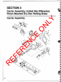
Carrier Assembly
38
,.•
Nut-Pinion
Washer-Pinion Nut
Pinion End Yoke Assembly (Includes Item 4 and 5)
End Yoke or Companion Flange
5 Deflector
6 Oil Seal-Pinion
7 Washer-Bearing Thrust
8 Outer Bearing Cone
9 Outer Bearing Cup
10 Shim-Pinion Bearing Preload Adjusting
11 Spacer-Flat
12 Capscrew-Carrier Mounting
13 Washer-Flat
14 Carrier
15 Cap-Differential Carrier
16 Washer-Flat
17 Capscrew-Bearing Cap Mounting
18 Lock-Bearing Adjusting Nut
19 Washer-Flat
20 Capscrew-Lock Mounting
21 Shim-Pinion Position (.003, .005, .010 Thick)
22 Inner Bearing Cup
23 Inner Bearing Cone
24 Gear and Pinion (Matched Set)
25 Side Bearing Cone
26 Side Bearing Cup
27 Adjusting Nut-Differential Side Bearings
28 Shatt-Differential
29 Pinior>-Differential
30 Thrustwasher-Oifferential Pinion
31 Side Gear-Differential
32 Thrustwasher-Differential Side Gear
33 Lock-Differential Shaft
34 Case-Differential (Standard)
35 Capscrew-Drive Gear Mounting
36 Capscrew-Brake Mounting (Optional)
37 Parking Brake (Optional)
38 Flange Hall-Limited Slip Differential Case
39 Cap Half-Limited Slip Differential Case
40 Shaft-Differential
41 Pinior>-Differential
42 Side Gear-Differential
43 Ring-Differential Side Gear
44 Plate-Differential
45 Diso--Differential
46 Diso--Differential (Dished)
47 Plate-Differential (Dished)
48 Capscrew-Differential Case Mounting
49 Housing-Axle (Housing Configurations
May Vary from Steer to Rigid)
50 Vent
51 Pir>-Dowel
52 Plug-Pipe (Drain and FilVLevel)
53 Bushing-Axle Pivot
54 Fitting-Grease
E
O
N
LY
1
2
3
4
NOTE: Use of safety glasses during disassembly assembly procedures is recommended.
1. If it becomes necessary to disassemble any parts
inside the carrier, it is suggested that the entire axle be
removed from the vehicle and held tight in a stand or
rack.
WARNING: When removing axle assembly,
make sure vehicle is properly suppo,r ted.
Improperly supported vehicle can cause
serious injury or death. Follow vehicle
manufacturers recommendations for
proper axle assembly removal procedures.
~
~
A
~
~
~
~
..,
4. Disconnect hydraulic lines to and remove steering
cylinder assemblies from the steer knuckle and carrier
anchor points.
5. Remove the tie rod assembly from the steer knuckle
anchor points.
NOTE: Do not alter the tie rod adjustment.
NOTE: If axle assembly is stUlln vehicle, be sure
carrier assembly is securely supported before it Is
separated from housing.
If axle assembly has been removed from vehicle,
be sure it is set securely in support stands with
carrier pinion positioned up.
6. Remove mounting bolts and washers from carrier
flange. Carrier assembly and axle housing is aligned
with dowel pins.
7. Remove carrier assembly from housing and mount
in suitable holding fixture such as a carrier repair
stand.
R
~
~
~
2. Remove drain plugs and drain lubricant from
planetaries and carrier housing .
3. At this time, remove wheel ends, and axle shafts.
Follow Procedures outlined in Wheel-End section of
manual.
NOTE: If non-steering axle skip steps #4 and #5
and proceed with step #6.
EF
..,
ER
EN
C
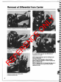
Removal of Carrier from Axle Housing
..,
..,
~
~
~
•
39
1. Remove adjusting nut lock from bearing caps.
O
N
LY
Removal of Differential from Carrier
ER
EN
C
E
5. Remove adjusting nuts.
2. Match mark one differential bearing cap and leg of
carrier with center punch or chisel for correct
reassembly. I
R
EF
6. Carefully lift the ring gear and differential sub·
assembly out of carrier.
3. Remove bearing cap retaining bolts.
4. Remove bearing caps.
40
NOTE: Prevent bearing cups from failing as you
remove differential.
Use care to avoid damage to ring and pinion
gears. If either is damaged, it must be replaced as
part of a matched set.
NOTE: If replacement of a damaged bearing cup or
cone is necessary, the cup and cone must be
replaced as a set.
.~
,~
~
•
~
•
.•
'
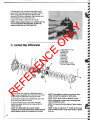
Differential Disassembly
LY
A. Ring Gear and/or Differential
Side Bearing Cones
O
N
3. Tap ring gear with a rawhide hammer to free it from
the case. Remove case and ring gear from vise.
NOTE: If ring gear and/or pinion shaft needs to be
replaced, ring gear and pinion shaft must be
replaced as a matched set.
ER
EN
C
1. If replacement of differential bearings is required,
remove differential bearings with a puller as shown.
E
B. Standard Differential
(One-Piece Case)
NOTE: It is recommended that whenever bearings
are removed, they are (regardless of mileage) to
be replaced with new ones.
NOTE: If replacement of a damaged bearing cup or
cone is necessary, the cup and cone must be
replaced as a set.
R
EF
1. Place holding fixture into vise. Place case onto
holding fixture as shown. Drive out lock pin.
2. If removal of ring gear from case is required, place a
few shop towels over the vise to prevent the ring gear
teeth from being nicked after it is free from the case.
Place case in vise. Remove ring gear screws and
discard them.
Ring gear screws are to be replaced with new ones at
time of reassembly.
2. Reposition case on holding fixture as shown. Drive
out cross pin using a drift and hammer.
41
=
3. Rotate gears until the pinion mate gears (small
gears) enter the large opening of the case. Remove
pinion mate gears and spherical washers. After
removal of the pinion mate gears, the side gears and
thrust washers can be easily removed.
Inspect and replace components as required.
O
N
LY
NOTE: Always replace gears as a complete set. Do
not mix new gears with old gears, as this may
cause uneven wear and short gear life.
E
C. Limited Slip Differential
I
ER
EN
C
1
6
7
3
Large Section of Case
Dished Plate
Dished Disc
Flat Plate
Flat Disc
Clutch Ring
Side Gear
Pinion Gear
Cross Shaft
Small Section of Case
Boll and Tapered Sleeve
11
4
R
EF
2
1
2
3
4
5
6
7
8
9
10
11
1. Punch mark both sections of differential case to
assure proper reassembly. Also mark end of the cross
shaft nearest the differential case punch marks.
2. Remove the small section of differential case, side
gear, clutch ring, plates, and discs.
3. Remove pinion gears, cross shafts, side gear,
clutch ring, plates, and discs from large section of
differential case.
NOTE: The differential has a serial number
stamped on the small case section. When ordering
parts, always include the complete part number.
42
NOTE: If any plates or discs are scored or worn,
entire set must be replaced on both sides.
NOTE: Clutch rings must be replaced In sets.
NOTE: Side gears or pinion gears showing wear
must be replaced in sets.
NOTE: If cross shaft shows signs of wear, replace
in sets.
NOTE: If wear is evident at "V" notch for the cross
shaft on either small or large case section, replace
as a set.
Pinion Disassembly
WARNING: Gear t8f1th may have sharp
edges. When handling gears, use care to
avoid personal injury.
NOTE: On the spline end of the pinion, there are
bearing preload shims. These shims may stick to
the bearing-pinlon-or even fall out. The shims
are to be collected and kept together since they
will be used later In assembly. Try not to mutilate
shims. If shims are mutilated, replace with new
ones; shims are available in thicknesses of .003",
.005", .010". and .030".
A
LY
NOTE: If carrier has optional pinion mounted
parking brake refer to pinion parking brake
section of manual for removal of brake assembly
from carrier.
ER
EN
C
E
1. Hold end yoke or flange with tool similar to the one
shown, and remove pinion nut and washer. Discard nut
as new one should be used at reassembly.
O
N
NOTE: If ring gear and/or pinion shaft needs to be
replaced, ring gear and pinion shaft must be
replaced as a matched set.
4. Pull out pinion seal with puller as shown. DISCARD
SEAL. Replace with new seal at time of assembly.
Remove bearing cone and outer pinion oil slinger.
R
EF
2. Remove end yoke or flange with tools similar to that
shown. If yoke or flange shows wear in the area of the
seal contact, it should be replaced.
3. Remove pinion by lapping with a rawhide hammer.
Catch the pinion with your hand to prevent it from
falling to the ground and being damaged.
5. Remove the inner bearing cup, if necessary, with
tools as shown.
NOTE: Shims are located between the bearing cup
and carrier bore and may also include an oil baffle,
depending upon the application. If shims and
baffle are bent or nicked, they should be replaced
attlma of assembly. Wire the stacks together and
43
LY
measure each. If stack has to be replaced, replace
with the same thickness.
NOTE: The front and rear axle carrier section may
vary in pinion bore depth due to the possibility of
the need for either a baffle or slinger or both.
The baffle serves the same purpose of assisting the
lube to flow up through the oil channels to lubricate
the pinion bearings. If used, they are part of the pinion
setting adjustment.
O
N
7. Remove inner pinion bearing cone, if necessary,
with tools as shown.
A
ER
EN
C
6. Turn nose of carrier down. Remove outer pinion
bearing cup as shown. Locate driver on back edge of
cup; drive cup out of carrier if necessary.
CAUTION: Do not nick carrier bore.
NOTE: Both baffle and slinger are part of the
pinion adjustment shims and are to be kept intact
for assembly.
NOTE: It is recommended that whenever bearings
are removed, they are (regardless of mileage) to
be replaced with new ones.
NOTE: If replacement of a damaged bearing cup or
cone is necessary, the cup and cone must be
replaced as a set.
E
'.
WARNING: Do not allow gear to fall. It can
strike legs or feet and may cause serious
injury. Gear teeth may have sharp edges.
When handling, use care to avoid cutting
hands.
Differential Assembly
A. Standard Differential (One-Piece Case)
the center of the small opening of the case. Line up
the other pinion mate gear with the gear which has
just been assembled. Rotate gears until the holes of
pinion mate gears are in direct line with the holes of
the differential case.
R
EF
1. Apply a small amount of grease on both side gear
hubs. Assemble new thrust washers onto side gears.
\
0,.<, ." ,\4
2. Assemble both side gears into case. Hold top side
gear up with your fingers. Assemble one pinion mate
gear. Rotate gears until pinion mate gear is directly in
44
3. After making sure the gears are in alignment, apply
a small amount of grease to the new spherical
•
O
N
LY
washers. Assemble washers between the gears and
case. Also line up the holes of the washers with those
of the gears and case.
4. Assemble cross pin. Make sure lock pin hole of the
cross pin is in a vertical position and lined up with the
lock pin hole of the case. Drive cross pin into case
with a hammer until the cross pin hole is in alignment
with the hole of the case.
1
E
ER
EN
C
B. Limited Slip Differential
5. Assemble lock pin. Peen metal of case over pin to
lock in place.
6
7
8
1
2
3
4
5
6
7
8
9
10
11
Large Section of Case
Dished Plate
Dished Disc
Flat Plate
Flat Disc
Clutch Ring
Side Gear
Pinion Gear
Cross Shaft
Small Section of Case
Bolt and Tapered Sleeve
11
R
EF
2
1. Lubricate all internal parts with axle lubricant
before assembly.
2. Alternately install plates and discs into large section
of case as illustrated.
NOTE: Install dished plate and disc with concave
surface toward case section.
3. Install clutch ring and side gear. Engage splines of
discs and clutch ring on side gear.
4. Assemble pinion gears on cross shafts. Assemble
cross shafts together.
5. Install cross shafts to large section of case so "V"
portion of cross shaft mates with "V" cut out in case.
6. Assemble side gear, clutch ring and clutch discs for
small case section on spider assembly as it sits on
work bench. Install case section being sure it seats
fully.
7. Tighten case section bolts to 95-100 ft. Ibs.
NOTE: Match case halves together by punch
marks.
45
2. Place bearing cone on hub of case. Use bearing
installer to seat bearing cone as shown.
Be sure they are fully seated.
NOTE: Be sure bearing cone and case bearing
journat are clean prior to assembly.
E
1. Place case assembly in a vise. Be sure flange face
of the case is free of nicks or burrs. Assemble ring
gear to case. Line up holes of the ring gear with those
of the case. Use new ring gear screws. DraiN up
screws alternately and evenly. Torque ring gear screws
to 120-140 ft. Ibs.
O
N
LY
C. Ring Gear and/or Differential Side Bearing Cones
ER
EN
C
Pinion Position and Assembly
A. Pinion Position
RING GEAR & PINION TOOTH PATTERN INTERPRETATION
When setting the pinion position, many of the service manuals required a final pinion position check by using
gauges that verified the dimension from the center line of the differential carrier (center line of ring gear) to the face
of the pinion (button).
This surface (button) is not used on all new gears for verifying the pinion position. The service tools will be used to
establish the proper amount of shims required prior 10- installing the pinion gear. The final pinion position will be
verified by using the GEAR CONTACT PATTERN METHOD, as described in this manual.
R
EF
The distance from the centerline of the ring gear to the
button end of the pinion for the Model 70 (Front and
Rear) axle is 3.500 inches approx.
View of ring and pinion set.
Ring gears and pinions are supplied in matched sets
only. Matching numbers on both the pinion and ring
gear are etched for verification. If a new gear set is
being used, verify the numbers of each pinion and ring
before proceeding with assembly.
46
On the button end of each pinion there is etched a
plus ( + ) number, a minus ( - ) number, or a zero (0)
number, which indicates the best running position for
each particular gear set. This dimension is controlled
by the shimming behind the inner bearing cup.
For example: If a pinion is etched + 3, this pinion
would require .003" less shims than a pinion etched
"0". This means by removing shims, the mounting
distance of the pinion is increased to 3.503" which is
just what a + 3 indicates. Or if a pinion is etched - 3,
we would want to add .003" more shims than would be
required if the pinion were etched "0". By adding .003
shims the mounting distance of the pinion was
decreased to 3.497" which is just what a - 3 etching
indicated.
If the old ring and pinion set is to be reused, measure
the old shim pack and build a new shim pack to this
Measure each shim separately with a micrometer and
add together to get total shim pack thickness from
original build up.
Ok! Pinion
Meriting
LY
NOTE: If baffle or slinger is bent or mutilated, it
should be replaced.
New Pinion Mlrklng
3
4
-2
-1
0
O
N
'I t
If a new gear set is being used, notice the ( + ) or ( - )
etching on both the old and new pinion and adjust the
thickness of the new shim pack to compensate for the
difference of these two figures.
For example: If the old pinion reads ( + ) 2 and the new
pinion is ( - ) 2, add .004" shims to the original shim
pack.
The above procedures also apply to pinion adjustment
on the front axle which includes the oil slinger between
the inner bearing cone and pinion, and baffle between
the inner bearing and carrier.
same dimension. If a baffle is in the axle assembly, it
is considered as part of the shim pack.
To change the pinion adjustment, shims are available
in thicknesses of .003", .005", and .010".
+1
+2
+3
+4
+ 0.008
+0.007
+0.006
+ 0.005
+ 0.004
+0.003
+0.002
+ 0.001
+3
+ 0.007
+0.006
+ 0.005
+ 0.004
+ 0.003
+ 0.002
+0.001
0
+2
+ 0.006
+0.005
+ 0.004
+ 0.003
+0.002
+ 0.001
0
0.001
0.002
+1
+ 0.005
+0.004
+ 0.003
+ 0.002
+ 0.001
0
- 0.001
0.002
0.003
0
+ 0.004
+ 0.003
+ 0.002
+ 0.001
0
-0.001
- 0.002
0.003
0.004
0
E
+<
0
0.001
O,OC)1
-0.002
0.003
-0.004
0.005
- 0.003
- 0.004
- 0.005
- 0.006
+ 0.003
+ 0.002
-2
+ 0.002
+ 0.001
0
- 0.001
- 0.002
-3
+ 0.001
0
- 0.001
- 0.002
- 0.003
- 0.004
- 0.005
- 0.006
- 0.007
0
- O.O()1
0.002
- 0.003
0.004
- 0.005
- 0.006
-0.007
- 0.008
-4
ER
EN
C
- 1
+ O.l){)1
Pinion setting chart shown. Use this chart as a guideline to set pinion.
R
EF
B. Pinion Assembly
1. Measure each shim separately with a micrometer
and add together to get total shim pack thickness. If
baffle is required, it is to be included in the shim pack.
If slinger is used between the inner bearing cone
and thrust face of pinion, the slinger is also to be
measured and included as a part of the total
shim pack.
2. Place the required amount of shims (and baffle if
used) in the inner bearing bore; drive the inner bearing
cup into carrier with tools as shown.
47
5. Install pinion into carrier.
Assemble outer pinion bearing cone, (slinger if used)
and end yoke onto pinion spline.
NOTE: Do not assemble preload shims or pinion
oil seal at this time
Use yoke installer (as shown) to assemble end yoke
onto spline of pinion.
ER
EN
C
E
3. Assemble the outer pinion bearing cup into carrier
as shown .
O
N
LY
n
R
EF
4. Assemble inner bearing cone (and a slinger if used)
on pinion; place bearing installer over pinion shaft as
shown. Drive bearing on shaft until it is completely
seated.
48
6. Assemble washer and pinion nut. Torque nut until it
requires 10 Ibs. inch to rotate pinion. Rotate pinion
several times before checking pinion position. This is
to seat the bearings and assure a more accurate
indication of the pinion position.
NOTE: The reason for not assembling preload
shims and new pinion oil seal at this time is due to
the possibility of having to adjust pinion preload
or pinion adjustment. It would be necessary to
again remove the seal, and as mentioned,
whenever seals are removed, they are to be
discarded because of possible damage.
7. Install the differential assembly into the carrier.
Refer to the ring gear/pinion tooth contact pattern and
differential installation sections of manual to properly
set the pinion position and backlash.
•
O
N
LY
Differential Installation
3. Be sure bearing cups are seated on bearing cones
and assemble differential bearing caps. Install bearing
cap bolts (finger tight only) so adjusting nuts can still
be turned.
E
1. Install ring gear and differential assembly into
carrier housing.
CAUTION: Care should be used when installing
ring gear and differential into carrier housing so
damage to ring gear, pinion, bearings, or bearing
bores do not occur.
ER
EN
C
NOTE: Make sure the "match marked" bearing cap
and leg of the carrier are on the same side for
correct reassembly.
EF
2. Install adjusting nuts in place. Thread in adjusting
nuts until all slack is removed between bearing cups
and bearings.
NOTE: Adjusting nuts must be Installed with side
of nut having the deeper recess facing the bearing.
Installed opposite, the adjusting nut would clamp
against the bearing cage restricting movement.
1. Dial Indicator
2. Adjusting Nut
3. Notch
4. Position a dial indicator on housing lip and index
indicator dial to back face of the ring gear. Zero
the indicator.
R
Turn adjusting nut on the backside of the ring gear in
until the indicator stops moving.
5. Next tighten adjusting nut on tooth side of ring gear
until bearing cup is seated.
Checking backlash
6. Position dial indicator on lip of differential housing
and indicate to side of one tooth on ring gear.
7. Move ring gear as far as it will go in one direction
before it moves the pinion.
1. Bearing Cup
2. Adjusting Nut
8. '0' the dial on the indicator face.
49
E
9. Force the ring gear in the opposite direction until it
contacts the pinion gear and observe Ihe dial face.
This figure is your backlash setting. Backlash should
be .00S·.00g·inch with no more variation around gear
than .003 inch.
O
N
LY
A reading larger than .009 in. is corrected by moving
ring gear closer to pinion. A reading smaller Ihan .005
in. is corrected by moving ring gear away from pinion.
Move the ring gear by tightening and loosening the
adjusting nuts. Both adjusting nuts must be moved the
same amount. A Y. turn 'in' with one nut should be
accompanied by a V. turn 'out' for the opposite nut.
10. When backlash is adjusted properly, rotating
torque at the pinion shaft nut should be 5·10 inch lb.
higher than the torque you had when setting pinion
shaft bearing preload.
Tighten adjusting nuts until adjusting nut locks can
be inslalled.
11. Torque the bearing cap bolts to 180·200 ft. Ibs.
ER
EN
C
Ring Gear and Pinion Tooth Contact Pattern
P'M)FllE
TOP LAND
I
......
I-,---- --r--TOE
I
LENGTHwtSE
lEARING
Me
_____ 1 __ _
HEEL
2. The tooth contact patterns should have the same
general shape and position as the ring gear teeth
shown above.
R
EF
Gear tooth nomenclature
The toe of the gear tooth is the portion of the tooth
surface at the end towards the center.
The heel of the gear toolh is the portion of the tooth
surface at the outer end.
The top land of a gear tooth is the surface of the top
of the tooth.
1. Paint ring gear teeth with marking compound and
rotate with pinion to obtain contact pattern.
50
3. If the pattern is concentrated more toward the heel
(as shown above), backlash must be reduced.
LY
proper mounting distance and contact pattern as
shown in step 2. This is accomplished by decreasing
the thickness of the inner pinion bearing shim pack as
described in the pinion assembly and position sections
of manual. Readjust pinion-to-ring gear backlash, as
required, once proper pinion mounting distance has
been established.
O
N
Recheck backlash as described in differential
installation section of manual. To reduce backlash,
loosen the right side adjusting ring until the measured
backlash is within specification. The tooth contact
pattern should now have the same general shape and
location as shown in step 2. If the contact pattern still
does not conform, less backlash than normal is
required. To avoid reducing differential bearing preload
excessively, further loosening of the right hand
adjusting ring should be accompanied by equal
tightening of the left hand adjusting ring. Place a dial
indicator directly on each adjusting ring to measure
the exact amount of additional adjustment. Decreasing
backlash moves the ring gear toward the pinion.
ER
EN
C
E
6. If pattern is concentrated at the tooth top land (as
shown above), the pinion is too far away from the ring
gear and must be moved closer to the ring gear to
establish its proper mounting distance and tooth
contact pattern. This is accomplished by increasing
the thickness of the inner pinion bearing shim pack as
described in the pinion assembly and position sections
of manual. Readjust pinion-to-ring gear backlash as
required once proper mounting distance has been
established.
R
EF
4. If the pattern is concentrated at the toe (as shown
above), more backlash is required. Recheck backlash.
To increase backlash , tighten the right side adjusting
ring further until the measured backlash is within
specification. The tooth contact pattern should now
spread across the ring gear tooth as in step 2. If the
contact pattern still does not conform, more backlash
than normal is required. To avoid increasing differential
bearing preload excessively, further tightening of the
right hand adjusting ring should be accompanied by
equal loosening of the left hand adjusting ring. Place a
dial indicator directly on each adjusting ring to
measure the exact amount of the additional
adjustment. Increasing backlash moves the ring gear
away from the pinion.
5. If a pattern is concentrated at the ring gear tooth
root as shown above, the pinion is too close to the ring
gear. It must be moved out and away to establish its
NOTE: When making changes. note that two
variables are involved: Example: If you have the
backlash set correctly to specifications and you
change the pinion position shim, you may have to
readjust the backlash to the correct specification
before checking the pattern. Refer to patterns as
shown.
PATTERN MOVEMENTS SUMMARIZED
(1) Decreasing backlash moves the ring gear closer to
the pinion.
Drive pattern (convex side of gear) moves slightly
lower and toward the toe.
Coast pattern (concave side of gear) moves lower
and toward the toe.
(2) Increasing backlash moves the ring gear away
from the pinion.
Drive pattern moves slightly higher and toward
the heel.
Coast pattern moves higher and towards the heel.
(3) Thicker pinion position shim with the backlash
constant moves the pinion closer to the ring gear.
Drive pattern moves deeper on the tooth (flank
contact) and slightly toward the toe.
Coast pattern moves deeper on the tooth and
toward the heel.
51
O
N
7. After the proper pinion position is determined,
temporarily remove the differential assembly from the
carrier for the proper setting of pinion bearing preload.
8. Remove pinion nut, washer, end yoke, slinger, and
bearing cone. Assemble preload shims (which were
removed during disassembly) onto pinion. Assemble
bearing cone, slinger.
NOTE: If carrier has optional pinion mounted
parking brake refer to pinion parking brake section
of manual for Installation of brake assembly,
pinion input yoke, washer, and nut to the carrier.
LY
(4) Thinner pinion position shim with the backlash
constant moves the pinion further lrom the
ring gear.
Drive pattern moves toward the top of the tooth
(lace contact) and toward the heel.
Coast pattern moves toward the top 01 the tooth
and slightly toward the toe.
11 . Using an inch lb. torque wrench as shown, rotate
pinion. Torque 01 pinion should read between 20-40
Ibs. inch (with new bearings).
To increase preload, remove shims; to decrease
preload, add shims.
ER
EN
C
E
12. If pinion parking brake is used remove pinion nut,
washer, and yoke. Refer to parking brake section of
manual to complete the installation 01 the brake
assembly to the carrier.
13. Reinstall the differential assembly into the carrier.
ReIer to the differential installation section 01 manual
to properly set the ring gear/pinion backlash. Torque
the differential bearing cap bolts to 180-200 It. Ibs.
,
'-,'
R
EF
9a. Apply a light coat 01 hypoid lubricant to the lip of
the pinion seal and assemble into housing.
9b. If pinion parking brake is used, install brake cover
plate and inner pinion seal at this time.
10. Assemble end yoke, washer, and new pinion nut.
Torque nut to 240-300 Ibs. It.
52
14. Install adjusting nut locks, mounting bolts, and
washers. Torque mounting bolts to 15-17 ft. Ibs.
~
=.
~
~
~
Installation of Carrier Assembly
into Axle Housing
1. Thoroughly clean inside of axle housing. Stone the
housing mounting surface if necessary to remove
burrs or nicks.
4. Assemble axle shafts and wheel end components
at this time following procedures outlined in the wheel
end section of manual.
LY
~
~
~
~
~
~
~
3. Install carrier assembly into axle housing, Install
washers, Torque bolts to 100·115 ft. Ibs. Bolts must be
E
~
NOTE: If steering axle, at this time Install tie rod
and steering cylinder assemblies following
procedures outline in those specific sections of
the manual for them.
Pinion Mounted Dry Disc Parking Brake
ER
EN
C
~
'2. Apply Permatex #2 gasket sealer to axle housing at
carrier mounting flange. A 1/4 inch bead around the
outside of all carrier mounting dowels and each bolt
hole is required,
TYPICAL BRAKE
"'TOIl
FIGURE 1
.......,.,.
BOI.T
EF
~
5. Clean Drain plugs and install in planetaries and
carrier housing. Fill with proper lubricant and to
required levels for planetary wheel ends carrier
housing. Inspect wheel ends and housing for oil leaks.
Take corrective action if leaks are incountered.
R
~
cleaned and threads coated with Loctite #271, or its
equivalent..
O
N
~
OOWtLI'IN
STATOR PLATE
STACK
ASSEMBLY
DETAIL
53
1
Parking Brake-e-Removal/Installation
5
\
O
N
LY
..-.Il=--- ·~,!milltl@!i±1!::::;;;;;11
\~"1'=:::"'-- iIl!V!!ij!!i!i!!!'
REMOVAL INSTRUCTIONS
•
ER
EN
C
E
1. Disconnect driveline from yoke shaft (6) and position away from brake.
2. Disconnect hydraulic pressure line used for releasing brake.
3. Remove nut (8) and washer (7) which retains yoke shaft (6) to splined pinion shaft on axle. Discard nut (8).
4. Remove four 1/2-13 UNC socket head cap screws (5) which attaches brake module (4) to cover plate (1).
5. Pull brake module (4) and yoke shaft (6) assembly away from cover plate (1).
6. Remove snap ring (3) from yoke shaft (6) and remove yoke shaft (6) from brake module (4).
7. Remove eight 9/16-18 UNF hex bolts (2) which attach cover plate (1) to carrier pinion input flange. Remove cover
plate (1) from axle.
INSTALLATION INSTRUCTIONS
Insert yoke shaft (6) into brake module (4) thru seal, bearing. and internal hex of spline ring.
Attach snap ring (3) in groove on yoke shaft (6) to retain spline ring.
Install cover plate (1) on carrier pinion input flange. Apply sealant between flange and cover plate surfaces.
Attach cover plate (1) to axle using eight 9116-18 UNF hex bolts (grade 5) and torque evenly to 90-100 ft. Ibs.
Install brake module (4) and yoke shaft (6) assembly into cover (1) engaging internal yoke shaft spline with
pinion spline. Orient brake module such that mounting bolt holes are in alignment and brake module seats
properly on cover flange. Be sure pressure and bleeder ports are facing up.
6. Insert four 112-13 UNC socket head cap screws (5) thru brake module (4) and into cover plate (I). Torque screws
evenly to 85 ft. Ibs.
7. Install washer (7) and new nut (8) on threaded end of spline shaft which engages yoke shaft (6). Torque nut (8)
to 240-300 ft. Ibs.
8. Reattach driveline on yoke shaft (6).
9. Connect pressure line to brake, bleed system, and test operation of brake on vehicle.
R
EF
1.
2.
3.
4.
5.
54
Parking Brakee--·OisassemblylAssembly
~
O
N
~
~
~
• NOTE: Earlier brakes do not have additional dowel
pins (10) Installed_ The plate stack (7, 8 & 9) is retained
only by shoulder bolts (5~
~
DISASSEMBLY
~
1. Remove case gasket (3) from cover (1).
2. Press out oil seal (2) from cover (1) if replacement required.
3. Remove outer spline (4) from brake module.
4. Remove four socket head shoulder bolts (5). A suitable
holding fixture is useful to hold brake in position.
CAUTION: Do not remove shoulder bolts without
pressurization of brake (approx. 300 psi) or damage
may result.
5. Remove primary disc (7), seven rotor discs (8) and seven
stator discs (9).
NOTE: Primary disc (7) Is offset from other stator discs
(9~ Reinstall new ptates In same sequence.
6. Remove four (4) socket head cap screws (6) which attach
spring plate (11) to pressure plate (18).
7. Remove spring plate (11) from pressure plate (18).
8. Remove case gasket (3) from spring plate (11).
9. Remove springs (12) from piston (13).
10. Remove piston (13) by carefully exerting hydraulic
pressure through brake release port on pressure plate (18).
11. Remove a-rings (15 & 17) and back-up rings (14 & 16)
from piston (13).
CAUTION: Care must be taken so as not to scratch or
mar piston.
12. Remove oil seal (21) from pressure plate (18~
13. Remove snap ring (20) and press bearing (19) Irom
pressure plate (18).
NOTE: A special removaf tool with a diameter toferance
of 2.990/2.980 Is required to press bearing from bore.
Therefore the bearing should be removed only"
replacement is required.
ER
EN
C
....
~
~.
~
~
~
R
EF
~
~
~
~
~
~
~
~
~
~
~
~
~ J.
~
~
4. Install back-up rings (14 & 16) on piston (13) toward
spring pockets.
5. Install a-rings (15 & 17) on piston (13). Be sure a-rings
are flat and all twists removed.
CAUTION: Care must be taken so as not to scratch or
E
~
~
~
Cover Plate
Oil Seal
Case Seal (2)
Outer Spline
Shoulder Bolt(4)
Cap Screw (4)
Primary Disc
Rotor Disc (7)
Stator Disc (7)
Dowel Pin (4)
Spring Plate
Springs (12)
Piston
Back-up Ring
O-Ring
Back-up Ring
O-Ring
Pressure Plate
Bearing
Retaining Ring
Oil Seal
LY
21
~
1
2
3
4
5
6
7
8
9
10
11
12
13
14
15
16
17
18
19
20
21
ASSEMBLY
LUBRICATE ALL RUBBER COMPONENTS FROM REPAIR
KIT WITH CLEAN TYPE FLUID USED IN THE SYSTEM.
1. Clean all parts thoroughly before assembling.
2. " removed, press new bearing (19) in pressure plate bore
(18). Insert snap ring (20).
3. Press seal (21) into pressure plate (18) until flush with
end of pressure plate.
mar piston.
6. Lubricate pressure plate piston bore (18) w~h type fluid
used in system. Carefully press piston (13) into pressure
plate (18). Be sure pistory is oriented such that threaded
holes in piston are in alignment with thru holes in spring
plate (11) when installed. Press piston until ~ bottoms on
pressure plate (18).
7. Install twelve springs (12) in piston (13).
8. Install case gasket (3) on spring plate (11).
9. Install spring plate (11) on pressure plate (18). Compress
springs (12) until spring plate bottoms on pressure plate.
10. Install four socket head cap screws (6). SEE NOTE
BELOW. Torque bolts to 55 ft. Ibs. A suitable holding fixture
is useful to hold brake in position.
11. Install stator discs (9) and rotor discs (8). Begin with a
stator disc (9) and a~ernate with rotor discs (8).
CAUTION: Slota In stator discs (9) should engage with
fixed dowel pins (10) in spring plate (11 ~
12. Inslall primary disc (7) offset from other stator discs (9).
13. Align tabs on primary disc (7) with thru holes in spring
plate (11) and partially screw in four socket head shoulder
bolts (5) into piston (13). SEE NOTE BELOW.
14. Using outer spline (4) align and center rotor discs (8) in
brake module. Be certain outer spline (4) is inslalled with
counterbored end towards bearing in brake.
15. Pressurize brake release port (approx. 300 psi) to
completely release discs. Torque shoulder bolls to 18 ft. Ibs.
and release pressure. A suitable holding fixture is useful to
hold brake in position.
16. Press oil seal (2) into cover (1). Note direction of seal
during installation.
17. Install case gasket (3) in cover (1).
NOTE: Botts should have Loctite applied. Place one or
two drops of Loctlte to the threads.
55
Parking Brake - Bleeding / Trouble Shooting
3. Apply sufficent pressure to release brake and check
for proper operation in system.
\
\
SERVICE DIAGNOSIS
CAUSE
PROBLEM
Brake drags or
runs hot
B. Oil in brake if designed for dry use
Dry linings generate 50% more torque
than linings saturated with oil. If the
brake has oil in it, check the type of oil
hydraulic or gearbox.
I. Gearbox oil
2. Hydraulic oil
Replace oil seal in brake
Check motor seal
Check piston seals
Note: Internal components will need to be
inspected, cleaned and
replaced as required.
C. Disc plates worn
The thickness of the disc stack set the
torque level. A thin stack reduces
torque.
Broken or set springs can cause reduced torque - a rare occurence.
Check disc thickness
E
D. Springs broken or
have taken a permanent set.
A. Low actuation
pressure
O
N
If there is back pressure in the brakes
Check filters, hose size,
actuation line, the holding torque of thlf'. restrictions in other
brakes is reduced.
hydraulic components.
B. Bearing failure
A. Stuck valve or
clogged
EF
Brake will not
release
B. Bad o-rings
R
C. Discs frozen
56
ACTION
A. Excessive pressure
in hydraulic system
ER
EN
C
Brake slips
EXPLANATION
LY
BLEEDING
1. Install brake in system and connect pressure lines.
2. Bleed pressure release section of brake by
pressurizing side inlet port and allowing air to escape
from top port. Pressure should not exceed 100 psi
during bleeding.
Check release pressure
The brake should be pressurized to
minimum of 20 psi over the specified
release pressure under normal operating cond~ions. Lower pressures will
cause the brake to drag thus generating heat.
Place pressure gauge in
bleed port & check
pressure with system on
If the bearing should fail, a large
amount of drag can be generated.
Brakes are designerd to come on when
system pressure drops below stated release pressure. If pressure cannot get
to brake, the brake will not release.
Replace bearing
If release piston will not hold pressure,
brake will not release.
Brakes are designed for only lim~ed
dynamic braking. A severe emergency
stop or prolonged reduced release
pressure operation may result in this
type of damage.
Place pressure gauge in
bleed port - check for
adequate pressure Replace defective line
or component
Replace o-rings
Replace disk stack
•
I
•
I
Inspection and Failure Analysis
This section is intended to serve as a guide for describing and explaining commonly encountered axte problems or
failures, and for recommending appropriate repair procedures.
PROBABLE CAUSE
RECOMMENDED REPAIR
Fracture of ring gear teeth
at the tooth heel.
1. Excessive loading of the gear beyond
design intent.
2. Incorrect gear adjustment (excessive
backlash).
Replace ring gear and pinion as matched
set.
Carefully follow the recommended
procedures for adjusting ring gear and
pinion backlash and tooth pattern.
Fracture of ring gear teeth
at the tooth toe.
1. Shock impact toading.
2. Incorrect gear adjustment (insufficient
backlash).
Replace ring gear and pinion as matched
set.
Carefully follow the recommended
procedures for adjusting ring gear and
pinion backlash tooth pattern.
O
N
LY
FAILURE MODE
Replace ring gear and pinion as a
matched set. Replace pinion bearings
taking care to set ring and pinion
position and bearing preloads properly.
Use correct lubricant, fill to proper level
and change at recommended intervals.
Overheated ring and pinion
gear teeth. Look for
discoloration of the gear
teeth .
1. Prolonged operation at excessive
temperatures.
2. Incorrect lubricant
3. Low oil level.
4. Contaminated lubricant.
All of the above can result in inadequate
lubricant film between tooth surfaces
which causes surfaces to overheat due
to excessive friction .
Replace ring and pinion as a matched
set.
Use correct lubricant, fill to specified
level and change at recommended
intervals.
Pitted drive pinion teeth.
1. Extremely severe service .
2. Insufficient lubrication.
Replace ring gear and pinion as a
matched set.
Use correct lubricant, fill to proper level
and change at recommended intervals.
Bent axle housing.
1. Vehicle overloading.
2. Vehicle accident.
3. Shock loading.
Replace axle housing.
1.
2.
3:
4,
Replace bearing cups and cones in
matched sets. Check roller ends for
excessive wear by comparing used
rollers with a new bearing.
Use correct lubricant, fill to proper level
and change at recommended levels.
EF
ER
EN
C
E
Scored and/or scuffed ring ~ . Insufficient lubrication.
and pinion gear teeth.
2. Contaminated lubricant.
3. Wrong lubricant or lubricant with
, depleted additives.
4. Worn pinion bearings which result in
pinion end play and incorrect ring and
pinion tooth contact.
R
Worn or pitted bearing.
Leaking oil seal.
Insufficient lubrication.
Contaminated lubricant.
Very severe service.
Normal wear.
1. Prolonged operation at excessive oil
temperatures.
2. Scored or dented yoke wear surface.
3 . Improperly installed oil seal.
4. Nicked or cut seal lip.
5. Contaminated lubricant.
Replace the oil seal and mating surface
if damaged.
Use correct lubricant, fill to proper level
and change at the recommended
intervals.
57
PROBABLE CAUSE
RECOMMENDED REPAIR
Excessive end yoke spline
looseness.
1. Severe service.
2. Loose pinion nut.
3. Pinion end play.
Replace the end yoke.
Check the pinion spline for excessive
wear.
Replace the ring gear and pinion as a
matched set if necessary.
Fatigue fracture of the
pinion gear teeth. Look for
clear-cui, wavy fracture
lines (beachmarks).
Severe service
Replace the ring gear and pinion as a
matched set.
~
Fracture of differential side
gears and pinion mates.
Shock loading of differential
components.
Replace differential side gears, pinion
mates, and cross shaft as a set.
;
Scoring and/or seizure of
cross shaft arms and
pinion mate gears.
1.
2.
3.
4.
Worn side gear splines.
(Excessive backlash)_
Severe service.
O
N
E
Excessive wheel spinning.
Inadequate lubrication.
Extremely severe service.
Unequal tire pressures.
LY
FAILURE MODE
Replace differential side gears and
pinion mates as a set. Replace worn
axle shafts.
4
Worn pinion roller bearing
retainer bore.
1. Severe service.
2. Excessive pinion end play.
3. Inadequate lubricalion.
4. Contaminated lubricant.
Replace carrier housing.
Check pinion for excessive endplay.
Use correct lubricant, fill to proper level
and change at recommended intervals.
Twisted or broken axle
shaft.
Severe vehicle operation.
Replace the shaft.
Fractured axle shaft at Ihe
flange.
1. Loose wheel bearing.
2. Bent axle housing.
3. Loose shaft to wheel hub bolts.
Replace the shaft.
Check housing distortion. Make certain
that wheel bearings are not worn or
misadjusted.
Noise on Drive
1. Excessive pinion to ring gear
backlash.
2. Worn pinion and ring gear.
3. Worn pinion bearings.
4. Loose pinion bearings.
5. Excessive pinion end play.
6. Worn differential bearings.
7. Loose differential bearings.
8. Excessive ring gear run-out.
9. Low lubricant level.
10. Wrong or poor grade lubricant.
11. Bent axle housing.
EF
ER
EN
C
Replace any scored washer and any
washer Ihat is .005 inch thinner than a
new one.
Use correct lubricant, fill to proper level
and change at recommended intervals.
R
58
•
1. Insufficient lubrication.
2. Improper lubrication.
3. Contaminated lubricant.
1. Axle noises heard on drive will
usually be heard on coast, although
not as load.
2. Pinion and ring gear too tight
(audible when decelerating and
disappears when driving.
4,
Replace differential side gears, pinion
mates, cross shaft and thrust washers
as a set.
Use correct lubricant, fill to proper level
and change at recommended intervals.
Scored or worn thrust
washer surfaces.
Noise on Coast
@
1. Adjust
2. Replace
3. Replace
4. Adjust
5. Adjust
6. Replace
7. Adjust
8. Replace
9. Replenish
10. Replace
11. Replace
1. Adjust or replace
(See above)
2. Adjsut
~
~
i
RECOMMENDED REPAIR
PROBABLE CAUSE
Intermittent
Noise
1. Warped ring gear.
2. Loose differential case bolts.
1. Replace
2. TIghten
Contant Noise
1.
2.
3.
4.
1. Replace
2. Replace
3. Replace
4. Replace
1. Replace
1. Worn differential side gears and
pinions.
2. Worn differential spider.
3. Worn differential thrust washers.
4. Worn axle shaft splines..
2. Replace
3. Replace
4. Replace
O
N
Noisy on Turns
Flat spot on pinion or ring gear leeth.
Flat spot on bearings.
Worn pinion splines.
Bent axle shaft.
LY
FAILURE MODE
SECTION 4
E
Specifications
Spicer Axle Lubricant Recommendations
ER
EN
C
IMPORTANT: Motor vehicles are operated under various requirements, conditions, and environments. This
manual specifies the minimum requirements that the lubricants should meet. However, it is recommended
that the lubricants specified by the vehicle manufacturer be used. They may provide additional lubricating
charaC1erlstics which may be required for your vehicle's operation. Contact your local service dealer or
refer to your owner's manual for obtaining proper lubricant specification.
To ensure proper lubrication and operating
temperature in Spicer Axles, it is important that proper
lubricants be used and correct lubricant levels be
maintained.
EF
RECOMMENDED LUBRICANTS
Multi-purpose gear lubricants meeting MIL Spec
L-2105C and suitable for API service classification
GL-5 are suggested as a minimum requirement for
Spicer Industrial axles. Refer to the chart below for
SAE viscosity grade versus ambient air temperature
range recommendations.
SAl 90
>
SAl: 80l0I-140
SAt I0Il-90
>
SAt HiI-90
SAl: HII
."
-c -40
• c
-21
-12
.15
.31
o ••
J
I
I
I
I
+I----~--~--+-~--r---+---~--~
I
I
.F-40
-15
.10
.10
.10
+32 +40
.'00
0,
A.. IIENT AlA TEMPERATURE
LIMITED SLIP DIFFERENTIAL LUBRICATION
R
Limited Slip Differentials impose additional requirements on lubricants which may not be covered by the above
specifications. Many vehicle manufacturers find it necessary to specify a special lubricant or limited slip additive for
use with Limited Slip Differentials. If required, these special lubricants are normally available through the original
equipment manufacturer.
KING PIN BEARING LUBRICATION
King pin bearings are lubricated by packing with grease. For grease packing it is recommended that a No.2 lithium
EP grease suitable for automotive wheel bearings be used. Contact your local vehicle service dealer or refer to
your owner's manual for obtaining the proper lubricant specification, and maintenance schedule.
WHEEL END WET DISC BRAKE LUBRICATION
Wheel end wet disc brakes impose additional requirements on lubricants which may not be covered by the above
specifications. Many vehicle manufacturers find it necessary to specify a special lubricant or additive for use with
them. Contact your local vehicle service dealer or refer to your owner's manual for obtaining.the proper lubricant
specification.
59
FASTENER STRENGTH IDENTIFICATION
IMPORTANT: Whenever fasteners are replaced, it is very important that the fastener be replaced with one
of equal or higher grade and quality. Fasteners should be torqued as recommended or specified for the
application.
WARNING: If fasteners of a lower grade or class are torqued to the requirements of a higher grade or class
fastener, it may result in component failure. (e.g. Grade 5 fastener torqued to the requirements of a grade 8
fSD
GRADE 7
GRADE 8
QSJ
O
N
GRADE 5
~
~
LY
fastener~
Customary (Inch) Bolts - Identification marks correspond to bolt strength - Increasing numbers
represent increasing strength.
SPECIAL GRADE
(High Slrength
Applications)
E
Inch grade fasteners can be identified by the radial lines embossed upon the head of the fastener and will
correspond to the fastener strength by two-lines less than actual grade (I.e. grade 8 fastener will display 6 radial
lines on the head).
NOTE: Male and female threads should be dry and unlubricated (unless purchased new as such~ clean
and free from scale and dirt.
WRENCH TIGHTENING TORQUE SPECIFICATIONS
ER
EN
C
POSITION
WRENCH TORQUE (FT. LBS.)
Drive Pinion Nut . .. ... . . ..... . . ... . . ...... . •. .. . . ....• .. .... .. . .. .• .. ... .. .. .... .. .. ... . ...... .240-300
Differential Bearing Cap Capscrews .. ..• .. . •.. . . . .•.. •.. . ... •.. •. . .. .... . ...... . .. . ...... . ....... 180-200
Ring Gear Capscrews .. ... .... .. ... .. . . . . . . .... . .. ..... •.. . ... .. .. .. • . . . ... . . .• . . .. .. .. . . ... . . .120-140
Limited Slip Differential Capscrews . . . ... . . . .. . . ..• . . . . .. '" • .. . ... . . • . . .. " . . . . ... • .. . ...• . . . .... .95-110
Carrier Assembly Mounting Capscrews .... . . .... ...... . .•. . . . . ... .. . .. .. •.. . . .. • . . . .. . ... •. .. ... . .100-115
Pinion Parking Brake Cover Plate Capscrews . .. .. . . ... . . • . .. .. ... . •. . •. .•.. ... ... . . . ... ... . .. . .. .. .90-100
Pinion Parking Brake Module Capscrews . . . . . ..... .. ......•... • ..... . . ... . . .. . • .. • .. • ... .. . .. .. .. .. . . . .85
King Pin Cap Capscrews .. .. . ....... ... . . ...... . .. . . .. ... .. .. .. ..• . .• . . . ... • ..•. . ........ . .. .. . . .. 80-90
Tie Rod and Steer Cylinder Socket Assembly Stud Nuts .. . ..... . . ..•.. • .. .. . . ...•..• . . . .... 140 Min. (Note A)
Tie Rod and Steer Cylinder Socket Assembly Clamp Nuts . ...........• . . • .. . .. . •.. • .. ....... .. ... . .. . .60-70
Spindle Mounting Nuts ...... .. . . . . .. . . . .. .. .. . . .. .... ... . • ... ... . .. . .. •. ...... . . • . .. .. .. ...... .. .80-100
Brake Rotor Mounting Capscrews . ..... , . . ' " ... . ... . .... . .•. . . . . . ... . .....•. . . ... • . .• . ........ .. .174-191
Wet Disc Brake Wheel Retainer Capscrews .... . . . . ..... . ... . . . ..... . ... . . . .. . ..... . ....... ... ..... . . . .45
Drive Flange Mounting Capscrews . .. . ....... .. .... . ..... .. . .. .. ... . . ... .. . . .. .. . . . . ....... .. ..... 90-100
EF
A) If cotter pin cannot be installed after minimum torque is attained, the nut must be advanced until cotter pin can
be installed.
BEARING PRELOAD SPECIFICATIONS
R
Pinion Torque to Rotate (New Bearings Only) . . . . ... .. .. . • . .•... .. . .. . ... • .... . ... . . .. . . .. . . . .. 20-40 in. Ibs.
Additional Torque to Rotate Required or Differential
Bearing Preload (New Bearings Only) .. . .. .. . ........ . , .. •....... . .. . . . . .. . .. , ..... . .5-10in. Ibs. higher than
required for Pinion
Bearing Preload Setting.
King Pin Bearing Torque to Rotate Knuckle ... .. .. .. .. . . .. .. .. .. . ... . .. . . . .. .... .. ... .. ... ....... 8-15 ft. Ibs.
Measurement is made less hub components, axle shaft, tie rod, and steering cylinder.
BACKLASH SPECIFICATIONS
Drive Pinion Ring Gear .. .. ... , .. ... . .. ..... .... , . .. . . .. . .. . .. . .. . .. . . . . .. .. .. .. .. .. .. . . . . . .005-.009 in.
60
ER
EN
C
E
O
N
LY
,e,
~~
~
~
~
~
)
)
)
R
,,
,,
,,
EF
~
~
~
~
E
ER
EN
C
EF
R
O
N
LY