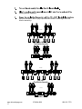
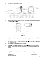
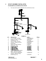
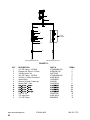
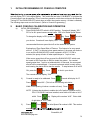
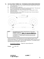
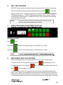
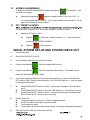
1
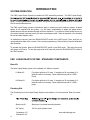
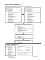
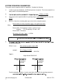
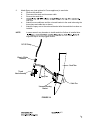
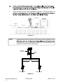
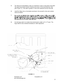
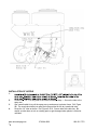
Ohio Valley Ag
Owensboro, KY
2610 W. Second St.
270.684.4202
866.561.7772
www.ohiovalleyag.com
Russellville, KY
101 N. Thruston Dr.
270.725.8948
866.940.2038
Liquid Ready System
T-Band / In-Furrow
Installation &
Service Manual
IMPORTANT
If the Console Displays Code,
Contact the FMC Support Center
816.581.6872
For All Other Questions, Please Contact OVA
270.684.4202
Do not attempt to use the FMC Liquid Ready At Plant System for any chemical other than those approved by FMC.
To do so will void warranty.
Operators Responsibilites:
1. User is responsible for proper system knowledge prior to use.
2. Apply chemicals according to proper environmental regulations.
3. Clean and flush at end of season.
4. Protect from freezing (winterize).
Warning!
Disconnect console before jump starting, charging battery, or welding on equipment.
Phone Numbers:
For Chemical Issues Call : 888.59FMCAG
For Service Issues Call : 866.561.7772
TABLE OF CONTENTS
INTRODUCTION
4
System Operation
System - Standard Components
System - Optional Components
4
4
5
5
6
7
9
12
12
Basic System Components
System Operating Parameters
System Diagrams
In-Furrow Appliances
Banded Application
INSTALLATION
13
Tank Installation
Stand Assembly Installation
Flow Monitor
Plumbing Assembly, Inlet
Outlet Assembly
Console and Cabling
Battery Connections
Operation
13
13
14
16
18
23
24
25
CONSOLE FEATURES
27
Console Calibration
Calculating Width CAL
Calculating Meter CAL
Flow Rate
Speed
28
28
28
28
28
CONSOLE PROGRAMMING
29
Initial Programming of Console Computer
Basic Console Calibration and Operation
Calculating Speed CAL
Valve CAL Feature
SP1/SP2 and Zero Speed Shut-off
Self Test Feature
Simulated Speed Adjustment Feature
Zero Speed Shut-off Feature
Low Limit Feature
Procedure to Access Console
Manual Operation Feature
Alarm Menu
Off Target Alarm
INITIAL SYSTEM SET-UP AND SYSTEM CHECK OUT
PREVENTIVE MAINTENANCE
TROUBLESHOOTING GUIDE
30
30
31
33
33
34
34
34
35
35
35
36
36
36
37
38
APPENDICES
PROCEDURE TO RE-CALIBRATE FLOW METER
PROCEDURE TO TEST FLOW METER CABLES
PROCEDURE TO TEST SPEED SENSOR EXTENSION CABLES
RADAR ADAPTER CABLE SELECTION GUIDE
SPRAY ARM-FURROW CONDITIONER JOHN DEERE & KINZE
SPRAY ARM-FURROW CONDITIONER WHITE PLANTERS
PUMP INSTALLATION WITH TRACTOR MOUNTED SADDLE TANKS
www.ohiovalleyag.com
4
270.684.4202
39
40
41
42
43
48
52
866.561.7772
INTRODUCTION
SYSTEM OPERATION
The FMC Liquid Ready System is intended for FMC Insecticide products. The FMC Liquid Ready-
water. If freezing temperatures are expected, the system should be safeguarded with R.V. antifreeze.
See Preventive Maintenance.
The FMC Liquid Ready system is intended to apply in volume per acre, relative to speed. A speed
sensor is not supplied with the system. It is the user’s responsiblity to obtain the speed sensor.
Speed sensors may be obtained through a Raven distributor. If you have a Radar Speed Sensor on
your tractor already, chances are all you need is an adapter cable. Refer to Appendix 4 for choosing
the correct radar adapter cable.
To calibrate the console, place the RUN/HOLD/OFF switch in the HOLD mode. Then, enter the required calibration data in the console. See console programming. Refer to Basic Console Calibration
and Operation.
To operate the System, place the RUN/HOLD/OFF switch in the RUN mode. This starts the pump
and opens on/off valve. To shut the pump and on/off valve off, place the RUN/HOLD/OFF switch to
the HOLD position.
FMC LIQUID READY SYSTEM - STANDARD COMPONENTS
Base Kit
The base Liquid Ready system kit is available in 2 different versions.
LV Base Kit
For planter with up to 12 rows. If equipping a 24 row planter 2 of
these kits will be necessary. These systems ship with 4.2 GPM
Pump.
HV Base Kit
For planter with up to 16 rows. If equipping a 32 row planter 2 of
these kits will be necessary. These systems ship with 5.3 GPM
pump
Plumbing Kits
The Plumbing kits for the Liquid Ready System are available in 4 row increments. Each kit consist
of :
Spray Arm Kit
Spray arm & universal mounting bracket
3/8” tubing
100’ for each 8 planter rows.
Owensboro, KY
Russellville, KY
4
www.ohiovalleyag.com
FMC LIQUID READY SYSTEM - OPTIONAL COMPONENTS
The following items are not included with the standard FMC LRS systems. Ohio Valley Ag offers
these at additional expense. For pricing, details & availability contact Ohio Valley Ag @ 866-581-7772
for details.
Valve Add-on KIT
This kit can be added to the base FMC LRS system so that two sections can be controlled for each
console. This kit provides the cabling, valve, switchbox & fiitings necessary to control two boom
sections.
In-Furrow
If in-furrow placement is desired, Ohio Valley Ag has several options available for purchase. These
include Stainless Steel Row Tubes, Schaffert Manufacturing’s Rebounder, and Keeton Seed Firmers.
Rebounder is a Trademark of Schaffert Mfg. & Sales
Keeton is a Trademark of Precision Planting Inc.
SYSTEM SPECIFICATIONS
CONSOLE:
4 Digit Display
Keyboard Data Entry System
Microprocessor Based
PWM Motor Control
Automatic Control relative to speed
CABLES:
15’ Console Cable
40’ Control Cable
PUMP:
LV BASE KIT
4.2 GPM
HV BASE KIT
5.3 GPM
FLOWMETER:
Turbine
.5 - 15 GPM
www.ohiovalleyag.com
5
270.684.4202
866.561.7772
BASIC SYSTEM COMPONENTS
Base kit required is based upon number of rows and application rate.
Base LV Kit FMC LFR
For 12 row systems.
Includes the following:
Base HV Kit FMC LFR
For 16 row systems
Includes the following:
QTY
1
1
1
1
1
1
2
7
1
1
1
1
1
1
QTY
1
1
1
1
1
1
2
7
1
1
1
1
1
1
DESCRIPTION
Assy,Stand, Incl:Flow Meter/Valve,Flow Tee, etc..
Cable, 40’, Product
Console, FMC CAPTURE
Cable, Console 15’
Remote Switch
Pump, 4.25 GPM w/ Heat Sink
Clamp, 40”, Worm Drive
Tie, Cable 14” Reg
Tefon Tape
Plumbing Fittings Kit
Spare Parts Bag
3/4”ID Braided Hose 25’
1”ID Braided Hose 10’
1/2”OD Tubing 100’
or
DESCRIPTION
Assy,Stand, Incl:Flow Meter/Valve,Flow Tee, etc..
Cable, 40’, Product
Console, FMC CAPTURE
Cable, Console 15’
Remote Switch
Pump, 5.3 GPM w/ Heat Sink
Clamp, 40”, Worm Drive
Tie, Cable 14” Reg
Tefon Tape
Plumbing Fittings Kit
Spare Parts Bag
3/4”ID Braided Hose 25’
1”ID Braided Hose 10’
1/2”OD Tubing 100’
+
FMC 4 Row Bag (1 per each 4 planter rows)
QTY
1
1
24
4
1
1
4
DESCRIPTION
Kit, T-Band/In Furrow Fittings
Hardware Bag - Bolts,Washers,Nuts,Hose clamps, Fittings
Tie Cable 14” Reg
Tie Cable 34” HD
Fitting Bag - Fittings for Fertilizer
4 Row Fertilizer Flow Indicator Parts Kit
1/4”OD Tubing 10’
+
Spray Arm Kit (1 per 4 Row Kit)
QTY
4
4
DESCRIPTION
Spray Arm
Universal Mounting Bracket
+
3/8” OD Tubing (1 roll per 8 planter rows)
QTY
1
DESCRIPTION
3/8” OD TUbing 100’
OPTIONAL COMPONENTS
Kit, Valve Add On
In-Furrow Placement
QTY
1
1
1
2
2
2
1
2
1
1
Row Tubes
1 required per row
Rebounder
1 required per row
Keeton Seed Firmer
1 required per row
DESCRIPTION
Valve, Manifold
Bracket
Fitting Tee, ORS
O-Ring #212
Fitting Cap, ORS
Lock, U-Clip
Fitting, Nipple, Reducing
Bolts 1/4-20 x 3” Lg
Switchbox
40’ Valve Cable
Owensboro, KY
www.ohiovalleyag.com
6
Contact Ohio Valley Ag @ 866-541-7772 for details
Rebounder is a Trademark of Schaffert Mfg. & Sales
Keeton is a Trademark of Precision Planting Inc.
Russellville, KY
SYSTEM OPERATING PARAMETERS
This system must be operated within its capabilities. Consider the following:
1.
In order to get even distribution, 10 PSI back pressure is required. This is also required for a
spray pattern in the banded application.
2.
.5 GPM to 15 GPM.
3.
The pump must be operated within its operating range, .5 to 2.2 GPM and at no more than
45 PSI.
4.
Below is a formula to calculate gallons per minute for the complete system.
GPM =
Planter width (in inches) x speed (in mph) x rate (gallons per acre)
5940
Planter width = Row spacing in inches x number of rows
example:
30” row spacing x 12 rows = 360
Planter width = 360 inches
360 inches x 5.5 mph x 3gpa = 1.0 GPM
5940
NOTE:
5.
the operating pressure.
GPM of 1 row =
example:
Row spacing in inches x mph x GPA
5940
30” x 5.5mph x 3.0 GPA
= .083 GPM
5940
TABLE 1
Wilger Nozzle DRA50-01E
PSI
CAPACITY
1 NOZZLE
IN GPM
PSI
CAPACITY
1 NOZZLE
IN GPM
10
20
30
40
.05
.07
.09
.10
10
20
30
40
.063
.088
.108
.125
From the example calculation, it can be seen that at .083 GPM, the operating pressure is
www.ohiovalleyag.com
7
270.684.4202
866.561.7772
6.
Below are listed Basic Guidlines for planters with row spacing of 30”.
This will give operating speed range @ 3 gallons per acre.
6 ROW
30 inch spacing
Speed Range
5 mph to 6.5 mph
6 ROW
30 inch spacing
Speed Range
5 mph to 8.5 mph
8 ROW
30 inch spacing
8 ROW
30 inch spacing
12 ROW
Speed Range
12 ROW
Speed Range
16 ROW
4.0 mph to 6.0 mph
16 ROW
4.5 mph to 8.5 mph
*24 ROW
*24 ROW max speed 8 mph
Optional pump # 063-0172-138
Required for 8.5 mph.
24 ROW
7.
For Planters with row spacing other than 30 inch:
In order to work within the pressure range of the nozzle, an adjusted applied rate must be
calculated. Only the water volume is changed. Follow label for chemical rates.
To calculate the adjusted applied rate use the following calculation:
______30__________ x 3.0 = Adjusted Applied Rate
Row Spacing in inches
example:
30 x 3.0 = 4.5 gpa (Adjusted Applied Rate)
20 (Row Spacing)
Owensboro, KY
www.ohiovalleyag.com
8
Russellville, KY
SYSTEM DIAGRAM
Single Width, Single On/Off Valve
15p
RAVEN
www.ohiovalleyag.com
9
FIGURE 1
270.684.4202
866.561.7772
SYSTEM DIAGRAM
Two Valves (Optional)
15p
RAVEN
FIGURE 2
Owensboro, KY
www.ohiovalleyag.com
Russellville, KY
10
SYSTEM DIAGRAM
Single Width, Single On/Off Valve
WIRING STANDARD - Single Valve
FMC
Liquid Ready
Console
WIDTH
CAL
RUN
1
SPEED
CAL
METER
CAL
2
3
4
5
DISTANCE
SPEED
TOTAL
VOLUME
TOTAL
AREA
9
0
FLOW
RATE
6
HOLD
OFF
RUN
CE
7
8
ENTER
Orange/White - Master
Connect to
Black - Boom 1
Black - Boom 1
Connect
to
Speed
Sensor
(not included)
Brown - Boom 2
(not used)
Blue - Boom 3
(not used)
Connect
to
Console Control
Cable
Green - Auxilary Ground
(optional use)
FIGURE 3
SYSTEM DIAGRAM
Two Width, Two On/Off Valves
WIRING OPTIONAL - Two Valve
FMC
Liquid Ready
Console
WIDTH
CAL
SPEED
CAL
METER
CAL
FLOW
RATE
Black - Boom 1
RUN
1
HOLD
OFF
RUN
2
3
4
5
DISTANCE
SPEED
TOTAL
VOLUME
TOTAL
AREA
7
8
9
0
CE
6
ENTER
Orange/White - Master
Valve Switchbox
On
On
Off
Off
Boom 1
Connect
to
Speed
Sensor
(not included)
Boom 2
White
to Ground
Brown - Boom 2
(not used)
Blue - Boom 3
(not used)
Connect
to
Console Control
Cable
Green - Auxilary Ground
(optional use)
FIGURE 4
www.ohiovalleyag.com
11
270.684.4202
866.561.7772
IN-FURROW APPLIANCES (Optional)
Several options are available for furrow conditioning. The Flexible Spray Arm allows you to deliver
Capture insecticide in a T-Band and utilize products such as Rebounders™ or Keeton® Seed Firmers. This method provides a zone of protection to uniformly and precisely treat and protect the seed
and soil prior to the closing of the furrow. The combination of a furrow conditioner device and Flexible Spray Arm will also allow the simultaneous use of multiple liquid planting time products to further
promote plant health and vigor.
NOTE:
Special precaution should be taken to not let any of the planter apparatus
interfere with the T-Band spray pattern.
BANDED APPLICATION (TYPICAL)
NOTE:
FIGURE 5
Owensboro, KY
www.ohiovalleyag.com
Russellville, KY
13
INSTALLATION
1.
TANK INSTALLATION
The tank is not provided with this unit. The tank and mounting brackets should be obtained
from the dealer for planter make and model. Locate the tank on the planter in an area that
will balance the weight of the tank and chemical.
2.
STAND ASSEMBLY INSTALLATION
center of
planter tool bar with hardware provided. Flow indicators must face forward.
6
6
6
5
5
5
5
4
6
4
4
4
3
3
3
2
2
2
2
1
3
1
1
1
Planter Toolbar
Planter Toolbar
FIGURE 6
www.ohiovalleyag.com
13
270.684.4202
866.561.7772
3.
FLOW MONITOR INSTALLATION
Assemble one of the Flow Monitor assemblies for every 2 rows on the planter.
NOTES:
1.
2.
3.
Apply lubricant to all o-rings (item 1) before assembling.
Apply pipe thread tape to all threaded connections before assembly.
All u-clips (item 2) should face front of assembly, see page 16 for front view.
8
6
7
1
9
5
4
2
3
FIGURE 7
4 Row Flow Indicator
QTY
4
4
2
2
2
2
2
2
2
2
DESCRIPTION
O-Ring - Viton
Lock, U-Clip
Body, Flow Indicator
Ball, Flow Indicator Red Celcon (Water)
Ball, Flow Indicator Red Glass (Fertilizer)
Retainer, Ball
Fitting, ORS Male x 1/4” Female NPT
Close Nipple 1/4mpt x 1/4mpt
90 Degree Ball Valve, 1/4” x 1/4” MNPT
Stem Connector 3/8 stem x 1/2 tube
Owensboro, KY
www.ohiovalleyag.com
PART #
CJ2046015
CJ2046004
CJ2046000
CJ2046007
CJ2046002
CJ20518VO
M1414
6JV380140EFG
8JENL380120
ITEM #
1
2
3
4
4
5
6
7
8
9
Russellville, KY
14
existing monitor assembly.
and nuts included in this kit (only required where holes in stand align with Flow
Monitor assembly).
5
5
4
4
3
3
2
1
Back View
5
5
4
4
3
3
2
2
2
1
1
1
Single Valve
Flow Monitor Assembly
6
5
5
4
4
3
3
2
1
6
5
5
4
Front View
6
6
5
5
4
4
4
3
3
3
3
2
2
2
2
1
1
1
1
5
5
4
4
3
3
2
2
2
1
1
1
Back View
Dual Valve
Flow Monitor Assembly
6
6
6
6
5
5
5
5
4
4
4
4
Front View
3
3
3
2
2
2
2
1
1
1
1
3
FIGURE 8
www.ohiovalleyag.com
15
270.684.4202
866.561.7772
4.
PLUMBING ASSEMBLY, INLET
FIGURE 9
1.
Mount the pump on the tool bar and close to the chemical tank. Use the large hose clamps
FIGURE 10
2.
Install the strainer between product tank and pump inlet. Use green strainer screen (100
Mesh) when water is the carrier, use red screen (50 mesh) when fertilizer is used as carrier.
3.
4.
5.
assembly. Use 3/4” hose. There must be a minimum of 5 ft. of hose between pump and
NOTE:
For Tractor Mounted Saddle Tanks, see Appendix 7.
Owensboro, KY
www.ohiovalleyag.com
Russellville, KY
16
From Product
Tank
11
13
Connect to
Flow Meter Inlet
14
1
2
13
11
11
10
3
6
9
8
12
Pump Inlet
7
4
4
Pump Outlet
5
FIGURE 11
QTY
1
1
1
2
25
1
1
1
1
1
1
1
3
10
2
1
DESCRIPTION
2”FPT x 2” Flange Manifold Fitting
Reducing Bushing 2”mpt x 3/4”fpt
3/4mpt x 3/4hb
#12 Hose Clamp
3/4” Braided Braided Hose
3/4” Hose Barb x Quad Port Fitting
Pump 12vdc 5 GPM
(Liquid Fertilizer Systems)
Pump 12vdc 4.2 GPM
(Standard Delivery Kit)
Heat Sink
Quad Port x 1/2”mpt Straight Fitting
Reducer Bushing 3/4”mpt x 1/2”fpt
Hose Barb 3/4”fpt x 1”hb
#16 Hose Clamp
1” Braided Hose
Hose Barb 1”mpt x 1”hb
In-Line Strainer 1”fpt - 50 Mesh
Screen - 100 Mesh Green
www.ohiovalleyag.com
17
270.684.4202
PART #
BANM200FPT
BANRB200075
BANHB075
HC12
HT034BR
DELSDFA34
DEL5950111E
ITEM #
1
2
3
4
5
6
7
RV0630172279
7
DEL50075
FJ20381039
BANRB075050
BANHBF075100
HC16
HT100BR
BANHB100
BANLST10050
BANLST1100
8
9
10
11
12
13
14
n/s
866.561.7772
OUTLET ASSEMBLY INSTALLATION
FOR BANDED & IN-FURROW APPLICATION
1.
Flow from the Flow Monitor Manifold will be distributed as shown.
1
2
3
4
5
Spray Arm
See Figure 9
6
DRA50 - 01E
7
8
SR20 025E
DRA50 - 01E
11
SR20 025E
5.
9
10
T-Band Spray Nozzle
12
FIGURE 12
QTY
1
4
2
1
4
4
4
4
4
4
4
DESCRIPTION
1/2” OD Tubing - 100’/Roll
Enlarger 3/8’ Stem x 1/2”tube
3/8”tube Union Tee
3/8” OD Tubing - 100’/Roll
3/8”tube x 1/8”mpt Connector
Nozzle Body
Strainer 50 mesh Combo-jet
Nozzle Seal - Viton
PART #
2T200806BK100
8JENL380120
8JUTC380
2T200604BK100
8JMC38018
CJ4050000
CJ40250
CJ40260VO
ITEM #
1
2
3
4
5
6
7
8
Tip/Cap Combo-jet SR220025E
(Black - Fertilizer as Carrier)
Tip/Cap Combo-jet DRA5001E
(Orange - Water as Carrier)
Nozzle Assy w/ Tip
CJ7007125E
10
CJDRA5001E
11
CJ50500VO
12
, KY
www.ohiovalleyag.com
1
1
2
3
4
5
6
In-Furrow
Nozzle Assembly
7
8
9
10
11
12
13
To
Rebounder/Seed Firmer/Row Tube
To
Rebounder/Seed Firmer/Row Tube
FIGURE 13
QTY
1
4
2
1
4
4
4
4
4
4
4
DESCRIPTION
1/2” OD Tubing - 100’/Roll
Enlarger 3/8’ Stem x 1/2”tube
3/8”tube Union Tee
3/8” OD Tubing - 100’/Roll
3/8”tube x 1/8”mpt Connector
Nozzle Body
Strainer 50 mesh Combo-jet
Nozzle Seal - Viton
PART #
2T200806BK100
8JENL380120
8JUTC380
2T200604BK100
8JMC38018
CJ4050000
CJ40250
CJ40260VO
Cap 1/4” fpt
1/4” tube Union
1/4” OD Tubing
CJ4027305
8JMC14014
BHE46428
www.ohiovalleyag.com
270.684.4202
ITEM #
1
2
3
4
5
6
7
8
10
11
12
866.561.7772
2.
Attach Spray arm (and optional In-Furrow appliance) to seed tube.
a.
Remove the seed box.
b.
Disconnect the seed monitor sensor cable.
c.
Remove the seed tube.
d.
See note.
e.
Attach furrow conditioner and the universal bracket to the seed tube using the
hose clamp and cable ties as shown.
f.
Attach the spray arm to the universal bracket after the seed tube has been reinstalled.
NOTE:
In some cases it may be easier to install seed tube if elbow is installed later.
tings with tape to avoid plugged nozzles.
3/8" OD Tubing
1/8mpt x 3/8tube
Connector
Seed Tube
T-band
Nozzle Assembly
Spray Arm
Cable Ties
Universal Mounting
Bracket
FIGURE 14
, KY
2
4.
Locate the large coil of1/2” tubing supplied with the system. This will be used to con-
FIGURE 15
NOTE:
Larger planters may fold, leaving 3 or 5 rows on a section of planter tool bar.
at the fold point. Care must be taken to ensure 1/2” tubing movement is not
restricted or damaged when folding planter.
Flow Indicator
Assembly
1/2" OD
Tubing
3/8" OD
Tubing
SR20 025E
SR20 025E
T-Band Spray Nozzle
T-Band Spray Nozzle
FIGURE 16
www.ohiovalleyag.com
21
270.684.4202
866.561.7772
5.
The Spray Arm (assembled in step 2) is intended to mount on the planter seed tube.
The spray arm nozzle should be positioned in place of the insecticide drop tube.
(Ref. Fiqure 17) If this tube is present, it will not be used and must be removed.
6.
Install the Spray Arm on the planter as shown in the manual for the user’s planter
make and model.
7.
tube with cable ties. Do NOT pinch the tube.
8.
Use the large cable tie to adjust the nozzle height to obtain a 5” to 7” band. The
large cable tie has a release mechanism to allow adjustment.
FIGURE 17
Owensboro, KY
www.ohiovalleyag.com
Russellville, KY
22
6.
CONSOLE AND CABLING
1.
2.
3.
4.
Mount the console P/N 063-0171-913 to a secure support inside the cab of the
vehicle.
Route the 15’ Console Control Cable P/N 115-0171-124 out of the cab and toward
the draw bar.
Turn RUN/HOLD/OFF switch to OFF and route the Red and White battery wires
to the 12-volt vehicle battery. Attach the two White battery wire to the NEGATIVE
(-) terminal and the Red battery wire directly to the POSITIVE (+) battery terminal.
(See Figure 5.) (DO NOT CONNECT RED AND WHITE WIRES TO THE STARTER).
Secure the battery wires with plastic cable ties. DO NOT tie the battery wires close to
the existing battery leads or any other electrical wiring.
Route the 40’ Flow Control Cable P/N 115-0171-125 from the draw bar to the Stand
Assembly. Always follow hydraulic lines. Use cable ties to secure cable. Be sure
cable does not pinch or stretch when planter is opened or closed.
CONSOLE MOUNTING
FIGURE 18
www.ohiovalleyag.com
23
270.684.4202
866.561.7772
BATTERY CONNECTIONS
FIGURE 19
Owensboro, KY
www.ohiovalleyag.com
Russellville, KY
24
WIRING OPTION 1
FIGURE 20
OPERATION
Plug the orange and orange/white wires together. When wired in this way, the pump will run and
the on/off valve will open when the RUN/HOLD/OFF switch is placed in the RUN position. The run
indicator on the console will be illuminated. Place the RUN/HOLD/OFF switch to HOLD. This will
shut the pump and the on/off valve off. The run indicator will now be off.
www.ohiovalleyag.com
25
270.684.4202
866.561.7772
WIRING OPTION 2
The FMC Liquid Ready System can be wired with a remote switch. The part number for
this switch is 063-0172-037. To do this, connect a remote switch between the orange and
orange/white wires.
Place the RUN/HOLD/OFF switch to RUN. Now the Remote Switch must also be on to enable
the system. The run indicator will also illuminate. To disable the system, place the remote
switch to off or place the RUN/HOLD/OFF switch to HOLD.
FIGURE 21
Owensboro, KY
www.ohiovalleyag.com
Russellville, KY
26
CONSOLE FEATURES
LCD DIGITAL READOUT - 4-digit
read-out of all functions.
FLOW CONTROL KEYS (DualFunction)
- Manually increase or decrease
it indicates that the system needs
to be calibrated.
mode. Also increases or decreases
simulated speed when “SPEED” key
is active.
WIDTH CAL KEY, METER CAL KEY,
FLOW RATE KEY, SPEED KEY Used to enter calibration numbers into
console to calibrate the system.
Run LED Illuminates when
Pump is running.
SPEED CAL KEY - Used to
calibrate speed sensor.
RUN/HOLD/OFF - Place switch in
RUN position when applying product.
Place switch in HOLD position when
shutting the system off (i.e., on end
rows).
To turn off all power to the console,
place switch in OFF position. Turning console OFF does not affect data
stored in the computer.
ENTER - Used only to enter
data into the computer.
TOTAL AREA KEY - Accumulates in acres.
FUNCTION KEYS - Used to
display data. TOTAL VOLUME
- Total Vol. applied.
DISTANCE KEY - Accumulates
in feet.
CE - Use like the CE key on a
calculator.
www.ohiovalleyag.com
27
270.684.4202
866.561.7772
CONSOLE CALIBRATION
1.
CALCULATING WIDTH CAL
WIDTH
CAL
3
2.
CALCULATING METER CAL
METER
CAL
5
3.
Width Cal = Row spacing in inches x number of rows
example: 30 inch row spacing x 16 rows = 480 inches
This number may need to be adjusted slightly. If over application occurs, adjust
the number down. If under application occurs, adjust the number upward. Typical
adjustment is about 5%. Write down the calibration number for future reference when
programming the console computer.
FLOW RATE
FLOW
RATE
This number is the gallons per acre to be applied.
example: 30 = 3.0 gallons per acre.
6
4.
SPEED
SPEED
CAL
4
This console applies relative to speed. This key calibrates the speed sensor to the
console. Refer to Calculating “Speed Cal”.
Owensboro, KY
www.ohiovalleyag.com
Russellville, KY
28
CONSOLE PROGRAMMING
When entering data into the Console computer, the entry sequence is always the same.
STEP 1
3
Depress the key in which you wish to enter data. The number of the key will be displayed.
STEP 2
-3-e
STEP 3
127
Depress the keys corresponding to the number you wish to enter (i.e. “1”, “2”, “7”). The numbers will
STEP 4
127
www.ohiovalleyag.com
29
270.684.4202
866.561.7772
1.
INITIAL PROGRAMMING OF CONSOLE COMPUTER
sole will display “SP1” in the digital display. This means the user must “CALIBRATE” or program the
Console before it can be operated. (This is a one-time operation, which does not have to be repeated.
Turning OFF the RUN/HOLD/OFF switch does not affect the console memory. All data is retained.)
The following steps must now be followed: (Refer to Console Programming.)
2.
BASIC CONSOLE CALIBRATION AND OPERATION
a)
INITIAL PROGRAMMING
1)
Place RUN/HOLD/OFF switch in HOLD position. Console will display “SP1”.
SP1 is for ALL speed sensors except radar. SP2 is for Radar Speed Sensor.
To change the display to SP2, press the
CE
key. Press
your choice. Console will now display “SoFF”. Press
ENTER
ENTER
to lock in
. It is
recommended that zero speed shut off not be used with this system.
Explanation of Zero Speed Shut off Feature: This feature is for zero speed
shut off. If “SoFF” is selected, when speed reaches 0, the pump will continue
to run until the RUN/HOLD/OFF switch is placed in HOLD. If S ON is
selected, the pump will shut off when speed drops to .7 mph or less.
When a zero speed shut-off has occured, the RUN/HOLD/OFF switch must
be turned to HOLD and then to RUN to restart the system. If a constant
speed greater than .7 mph is not attained within 10 seconds, the zero speed
shut-off will be enacted again. If a remote implement switch is used, raising
and lowering the planter will re-start the system. To step between S off and S
ON, press the
CE
ENTER
key. Press
to lock in your choice.
The console will now display “CAL”.
WIDTH
CAL
2)
Console is ready to be calibrated. Press
. Console will display “b-01”
3
Press
ENTER
. Press XXX. (This is from the following calculation:
Width = Row spacing in inches x number of rows). Press
ENTER
.
NOTE: If planter has clutches to enable shut off of portion of planter and kit
P/N 117-0159-851 has been installed, enter width of left side as “b-01”
width. Press
key. Display will now show “b-02”. Enter width
1
of right side as “b-02” width.
3)
Press
SPEED
CAL
.
Press
. The initial Speed Cal number is 598. This number
ENTER
4
must be
Russellville, KY
www.ohiovalleyag.com
30
4)
Press
METER
CAL
. Press
.
ENTER
Enter in the Meter Cal number found on the Flow
5
Meter Calibration tag. Press
5)
FLOW
RATE
Press
.
Press
.
ENTER
.
ENTER
Enter in 3.0 for 3.0 gal/acre. Press
.ENTER
6
6)
NOTE:
If a simulated speed is desired, refer to Self Test Feature.
To clear out program and return to SP1, place RUN/HOLD/OFF switch to OFF. Press
and hold
3A.
CE
and at the same time, place the RUN/HOLD/OFF switch to HOLD.
CALCULATING “SPEED CAL” FOR RADAR SPEED SENSORS
1)
Complete “INITIAL CONSOLE PROGRAMMING” before doing this procedure.
2)
Enter “0” in key labelled
DISTANCE
.
7
3)
Enter a SPEED CAL of 598 in key
SPEED
CAL
.
4
4)
Drive 1 mile. To achieve the most accurate calibration, accelerate and decelerate
slowly.
CAUTION:
Do not use vehicle odometer to determine distance. Use section
lines or highway markers.
5)
Read DISTANCE by depressing key labelled
DISTANCE
.
7
a)
b)
DISTANCE should read a value of approximately 5280. If it reads between
5260-5300, the SPEED CAL for your vehicle is 598.
If the DISTANCE display reads any other value, perform the following
calculation:
Multiply the SPEED CAL by the actual distance, then divide the sum by
the value in DISTANCE display. This will give the corrected value to enter for
SPEED CAL. Round off to the nearest 3 digit whole number.
EXAMPLE:
SPEED CAL = 598
Actual distance = 5280
Assume the DISTANCE display reads 5000
= 598 x 5280 = 631.4
5000
The corrected number to enter for SPEED CAL is 631.
6)
7)
Enter the number calculated for SPEED CAL.
Verify the corrected SPEED CAL number calculated in Step 5:
a)
Zero out the DISTANCE display as in Step 2.
b)
Enter the corrected SPEED CAL number as in Step 3.
c)
Repeat Steps 4 and 5a. If DISTANCE value does not read correctly, repeat
Steps 5b, 6, and 7.
www.ohiovalleyag.com
3
270.684.4202
866.561.7772
3b.
CALCULATING “SPEED CAL” FOR WHEEL DRIVE SPEED SENSORS
1)
2)
3)
4)
5)
Place a chalk mark or tape onto the vehicle tire that has the Speed Sensor mounted
to it as shown below.
Mark the initial spot on the ground.
Drive vehicle straight ahead counting 10 full revolutions of the wheel. The mark must
stop at the same position it was in when the vehicle started.
Measure the distance from the ground starting mark to stopping mark in inches
(round off fractions).
Write down this distance as the SPEED CAL number; keep it for future reference
when programming the console.
NOTE:
This measurement is critical to the performance of the console.
MEASURE CAREFULLY
measuring. Measure tire in type of soil in which you will be planting.
Circumference of tire will vary when measured in soft soil versus
hard packed soil. For best results, measure severeal times and
average the results.
Large tires and very low speed applications may require additional magnets to insure
accurate speed readings. Any even number of magnets may be used as long as they are of
alternating color and equally spaced. After calculating “SPEED CAL”, this number must be
adjusted according to the number of magnets used.
Normal Number of Magnets
Actual Number of Magnets
Example:
x Speed Cal = Adjusted Speed Cal
4 x 1200 = 800
6
, KY
3
4.
VALVE CAL FEATURE
VALVE CAL
1)
The initial Control Valve calibration number is 123. After operating the system, this
VALVE SPEED DIGIT
BRAKE POINT DIGIT
DEAD BAND DIGIT
To change the Valve Cal setting, depress the key labelled
METER
CAL
for 5 seconds.
5
The display will show the current valve calibration number. Enter a new valve
calibration number if desired.
Valve Speed Digit:
Controls response time of pump motor.
CAUTION:
Adjusting response time too fast
will cause the system to oscillate.
Range:
Brake Point Digit:
1 to 9
Sets the percent away from target rate at which the
control begins braking, so as not to over-shoot the
desired rate.
Range:
Dead Band Digit:
0 to 9
0 = 5%
1 = 10%
9 = 90%
Allowable difference between target and actual
application rate, where rate correction is not performed.
Range:
5.
1-Slow
9-Fast
1 to 9
1 = 1%
9 = 9%
SP1 OR SP2 AND ZERO SPEED SHUT-OFF
Press and hold
TOTAL
AREA
key. After 5 seconds, the display will show either SP1 or SP2, then
0
alternate to S off or S ON.
SP1
SP2
S off
S ON
www.ohiovalleyag.com
3
is for all speed sensors except radar.
is for radar and GPS speed sensors.
zero speed shut off has not been selected.
zero speed shut off has been selected.
270.684.4202
866.561.7772
6.
SELF TEST FEATURE
SELF TEST allows speed simulation for testing the system while the vehicle is not moving.
SPEED
Enter the simulated operating speed by depressing the key labelled
for 5 seconds.
8
Display will show “tESt”. If 6 MPH is desired, enter 6.0 (See CONSOLE PROGRAMMING).
The display will show 6.0. The SELF TEST speed will clear itself when motion of vehicle
is detected by the Speed Sensor. A SPEED CAL value of 900 or greater is recommended
when operating in this mode.
NOTE:
7.
To prevent nuisance clearing of self-test speed, disconnect speed
connector when radar speed sensors are used.
SIMULATED SPEED ADJUSTMENT FEATURE
5.5
DEFINITION OF KEYS
SPEED
Press
, then:
8
Depressing
will cause the Simulated Speed to INCREASE by 0.1 MPH.
1
Depressing
will cause the Simulated Speed to DECREASE by 0.1 MPH.
2
NOTE:
8.
ZERO SPEED SHUT-OFF FEATURE
During initial programming, a choice must be made to use or not to use this feature.
If you desire not to use Zero Speed Shut-Off, press the
To step the display to S ON, press the
press
ENTER
CE
ENTER
key when display is S off.
key. If you desire to use Zero Speed Shut-Off,
when the display is S ON.
If S ON has been selected, the console will shut the injection pump off when speed drops
below .7 mph. When a zero speed shut-off has occurred, the RUN/HOLD/OFF switch must
be placed to HOLD and then to RUN to re-start the system. If a constant speed greater that
.7 is not attained within 10 seconds, the zero speed shut-off will be enacted again. If a speed
, KY
3
greater than .7 is detected after this 10 second period and the console RUN/HOLD/OFF
switch is in RUN, the alarm will sound to alert operator that product is not being applied. Restart the system or place the RUN/HOLD/OFF switch to HOLD.
9.
LOW LIMIT FEATURE
FLOW
RATE
6
be entered. Enter this rate in gallons per minute. When slowing down, the console will not ad
just the rate below this limit. “LL” will be displayed, indicating this limit has been reached.
To determine gal/min, use the following formula:
RATE
gal/min =
X
(Gal/Acre)
Width
X
SPEED
(Row spacing in inches
5940
(mph)
x # of Rows)
10.
PROCEDURE TO ACCESS CONSOLE
After purchase of FMC Insecticide, an 8 digit code is available from your FMC Representative.
This code will allow access the console for 1 year from December 1 thru November 30th.
He will require the serial number from the console.
STEP 1
When the console displays the message CODE, press the
key. The display
2
ENTER
code. Verify they are correct, then press
STEP 2
Press the
.
ENTER
key. The display will show C2. Press the
ENTER
key. Press the
2
numbers of the last 4 digits in the code. Verify they are correct, then press
ENTER
If
the console has been successfully unlocked, the display will no longer show CODE. If
SP1 message appears, refer to CONSOLE CALIBRATION. If no message appears,
console retains calibration as previously programmed.
NOTE:
If CODE message is displayed repeat process starting with Step 1.
11.
MANUAL OPERATION FEATURE
DISTANCE
a)
Press and hold
for 5 seconds and “C on” displays. Press
CE
to alternate
7
between “C on” (automatic control) and “C oFF” (manual control).
FLOW
RATE
b)
6
play. To increase Flow Rate, press
.
1
NOTE:
.
2
Console defaults to automatic mode. Switching RUN/HOLD/OFF switch to
OFF, then HOLD returns the console to automatic control.
www.ohiovalleyag.com
3
To decrease Flow Rate, press
270.684.4202
866.561.7772
12.
AUDIBLE ALARM MENU
To display the AUDIBLE ALARM MENU, depress key labelled
will show in the display.
a)
Momentarily depressing
CE
for 5 seconds. “A on”
1
toggles the display between “A on” and “A off”. “A
on” means audible alarm is enabled. “A off” means audible alarm is disabled. The dis
play will still indicate an alarm condition.
13.
OFF TARGET ALARM %
Off Target value is preset to 30%, but may be changed to a different number.
1)
Adjusting Off Target % Value.
a)
Depress
WIDTH
CAL
for 5 seconds. Display will show “-or-”. Enter desired new
3
number for OFF TARGET ALARM %.
b)
Depress
ENTER
to store selection.
INITIAL SYSTEM SET-UP AND SYSTEM CHECK OUT
1.
Fill tank with water.
2.
Place RUN/HOLD/OFF to HOLD.
3.
Verify calibration data has been entered in console.
4.
Press the key labelled
FLOW
RATE
. Enter the desired Rate Per Acre.
6
SPEED
5.
Press the key labelled
. Enter the desired simulated speed. This number should
8
match the “while planting” tractor speed.
6.
If the system has been wired to run when the Remote switch is on, place the RUN/HOLD/
OFF switch to RUN. Place the Remote switch to ON. Red LED shall be on. Verify the pump
is running and has primed.
7.
A.
B.
C.
Place RUN/HOLD/OFF switch to HOLD. Verify pump has stopped. Run LED shall
be off.
Place RUN/HOLD/OFF switch to ON. Run LED shall be on. Verify pump is running.
Place RUN/HOLD/OFF switch to HOLD. Console should display programmed rate.
Run LED shall be off. Verify pump is not running.
8.
System Check Out.
A.
Verify spray pattern for each row. Check for plugged nozzles.
B.
Verify Flow Indicator balls are at the same height.
C.
Check system for leaks.
D.
Verify system can achieve rate at desired speed. See System Operating Parameters.
9.
After initial system check out, drain water from tank.
, KY
3
PREVENTIVE MAINTENANCE
Preventive maintenance is most important to assure long life of the Application System. The following
maintenance procedures should be followed on a regular basis:
1.
PUMP:
Pump check valves may need to be changed after prolonged exposure to
Insecticide. Replace check valve assembly with part 219-0000-103.
2.
TANK(S):
for extended periods of time. Keep system clean.
3.
FLOW INDICATOR ASSEMBLY:
protect system from freezing with RV anti-freeze. Cover Flow Indicator to
protect from sun light. Direct sun light and prolonged contact with chemical will
degrade the clear plastic in the Flow Indicator.
4.
HOSES AND FITTINGS:
Inspect on a regular basis for wear and abrasion, softening, swelling and leaks.
Replace as needed.
5.
CABLES:
Inspect regularly for wear and abrasion. Protect connections with di-electric
grease. Clean any corrosion that may develop. Always tie up cables to keep
them away from hot surfaces and from being caught or stepped on.
6.
FLOWMETER:
system will not be used for extended periods of time. Keep system clean.
DO NOT LET SYSTEM FREEZE.
NOTE:
Parts damaged due to freezing will not be covered under warranty.
www.ohiovalleyag.com
3
270.684.4202
866.561.7772
TROUBLESHOOTING GUIDE
PROBLEM
CORRECTIVE ACTION
1)
NO DISPLAY LIGHTS WITH POWER ON.
1)
2)
3)
Check fuse.
Check battery connections.
Check operation of OFF/HOLD/RUN
switch.
2)
A DIGIT CANNOT BE ENTERED VIA
KEYBOARD.
1)
Return Console to your dealer
for service.
3)
CONSOLE DISPLAYS “SP1” WHENEVER
VEHICLE ENGINE IS STARTED.
1)
Check battery voltage and battery
connections.
5)
CONSOLE DISPLAYS “SP1” WHENEVER
MASTER SWITCH IS TURNED ON OR
OFF.
1)
Check battery voltage and battery
connections.
6)
ONE DISPLAY DIGIT HAS ONE OR
MORE MISSING SEGMENTS.
1)
Return Console to Dealer for service
7)
SPEED DISPLAY “0”.
1)
Perform cable test. See Appendix 3.
8)
RATE READS “0”.
1)
Verify speed value is entered.
3)
See Appendix 2.
Verify pump is running.
9)
RATE IS ERRATIC.
1)
2)
Verify console is programmed correctly.
Verify system pressure does not
exceed 45 psi.
10)
PUMP WILL NOT PRIME.
1)
Verify On/Off valve is open.
3)
Replace check valve assembly.
See Appendix 5.
1)
ly.
2)
3)
Verify Console is programmed correct-
11)
12)
PUMP WILL NOT RUN.
SYSTEM NOT ACCURATE
1)
2)
Verify cable connections.
Apply 12 VDC to pump leads.
Verify pump runs. If not, replace pump.
Verify correct calibration data entered
in console.
See Appendix 1, Procedure to ReCalibrate Flowmeter
, KY
3
APPENDIX 1
PROCEDURE TO RE-CALIBRATE FLOW METER
IMPORTANT:
1)
2)
Enter a METER CAL number of 10 [38] in the key labelled
Enter a TOTAL VOLUME of 0 in the key labelled
TOTAL
VOLUME
METER
CAL
.
5
.
9
3)
Place all On/Off valves on stand assembly to OFF.
4)
Remove a tube from stand assembly and place it into a calibrated 5 gallon [19 liter] container.
5)
Place at appropriate On/Off valve for the tube that was just placed into the 5 gallon container.
Place RUN/HOLD/OFF switch to RUN. Pump exactly 10 gallons [38 liters].
6)
Readout in TOTAL VOLUME is the new METER CAL number. This number should be within
+/- 3% of the calibration number stamped on the tag of the Flow Meter.
7)
VOLUME display before retesting).
8)
liquid (i.e. 250 gallons). DO NOT RELY ON GRADUATION NUMBERS MOLDED INTO
APPLICATOR TANK. Empty the applicator tank under normal operating conditions. If the
number displayed under TOTAL VOLUME is different from the predetermined amount of
measured liquid by more than +/- 3%, complete the following calculation:
EXAMPLE:
METER CAL
TOTAL VOLUME
Predetermined amount of measured liquid
Corrected METER CAL
= 1600 [422]
= 260 [984]
= 250 [946]
=
METER CAL x TOTAL VOLUME
Predetermined amount of measured liquid
ENGLISH UNITS:
METRIC UNITS:
= 1600 x 260 = 1664 = [422] x [984] = [439]
250
[946]
Corrected METER CAL
9)
= 1664 [439]
Enter corrected METER CAL before resuming application.
www.ohiovalleyag.com
270.684.4202
866.561.7772
APPENDIX 2
PROCEDURE TO TEST FLOW METER CABLES
Disconnect cable from Flow Sensor. Hold Flow Sensor cable so that the keyway is pointing in the
12 o’clock position:
PIN DESIGNATIONS
2 o’clock socket location is ground.
10 o’clock socket location is power.
6 o’clock socket location is signal.
VOLTAGE READINGS
1) 2 o’clock socket to 6 o’clock socket = +5 VDC.
2) 2 o’clock socket to 10 o’clock socket = +5 VDC.
PROCEDURE TO CHECK CABLE:
1)
2)
Enter a METER CAL number of one (1) in key labelled
Depress key labelled
TOTAL
VOLUME
METER
CAL
.
5
.
9
3)
Disconnect the pump power connector. Place RUN/HOLD/OFF switch to RUN.
4)
With small jumper wire (or paper clip), short between the 2 o’clock and 6 o’clock sockets with
a “short-no short” motion. Each time a contact is made, the TOTAL VOLUME should increase
by increments of 1 or more counts.
5)
If TOTAL VOLUME does not increase, remove the section of cable and repeat test at connector next closest to Console. Replace defective cable as required.
6)
Perform above voltage checks.
7)
If all cables test good, replace Flow Sensor.
NOTE:
After testing is complete, re-enter correct METER CAL numbers before application.
Place RUN/HOLD/OFF switch to HOLD. Reconnect pump power connector.
, KY
4
APPENDIX 3
PROCEDURE TO TEST SPEED SENSOR EXTENSION
CABLES
Verify that the Console is in the SP1 Speed Sensor mode while testing the cable. Disconnect extension cable from Speed Sensor Assembly cable. Hold extension cable connector so that keyway is
pointing in the 12 o’clock position.
PIN DESIGNATIONS
2 o’clock socket location is power.
10 o’clock socket location is ground.
6 o’clock socket location is signal.
VOLTAGE READINGS
1) 10 o’clock socket to 6 o’clock socket = +5 VDC.
2) 10 o’clock socket to 2 o’clock socket = +5 VDC.
If a +5 VDC voltage reading is not present, disconnect the Flow
Sensor cable. If the Speed reading is restored, Test the Flow
Sensor cable per Appendix “PROCEDURE TO TEST FLOW
METER CABLES”.
PROCEDURE TO CHECK CABLE:
l)
Enter SPEED CAL number of 1000 in key labelled
Depress key labelled
.
4
DISTANCE
2)
SPEED
CAL
.
7
3)
With small jumper wire (or paper clip), short between the 10 o’clock and 6 o’clock
sockets with a “short-no short” motion. Each time a contact is made, the DISTANCE total
should increase by increments of 1 or more counts.
4)
If DISTANCE does not increase, remove the section of cable and repeat test at connector
next closest to Console. Replace defective cable as required.
5)
Perform above voltage checks.
6)
If all cables test good, replace Speed Sensor.
NOTE: After testing is complete, re-enter correct SPEED CAL number before
application.
www.ohiovalleyag.com
4
270.684.4202
866.561.7772
APPENDIX 4
RADAR ADAPTER CABLE SELECTION GUIDE
Radar Type
Dickey john
Magnavox/Phillips
TRW
Tractor Type
Case IH
Cable Part #
RV1150159517
Agco-Allison 94/95/96
Ford ***
White *
John Deere **
Challenger *
Cat C-Mod, D-Mod
Row Crop 35,45,55
Challenger
John Deere 7000/8000/9000
Series
Ford
Genesis/Versatile
New Holland 1996
Other
John Deere **
John Deere 7000/8000/9000
Series
Other
Case
Other
RV1150159529
RV1150159519
RV1150159518
RV1150159627
RV1150159700
RV1150159709
RV1150159526
RV1150159519
RV1150159700
RV1170159462
RV1150159432
RV1150159463
TABLE 1
*
**
***
1990 model year or later with factory installed performance monitor.
1990 model year or later with factory installed performance monitor.
Not used for 7000/8000/9000 series tractors.
1990 model year or later with factory installed performance monitor.
Not used for Gensesis/Versatile tractors.
, KY
4
APPENDIX 5
INSTALLATION INSTRUCTIONS FOR
SEED SHIELD SPRAY ARM® WITH SEED SHIELD FURROW CONDITIONER®
SEED SHIELD SPRAY ARM® WITH REBOUNDER®
SEED COVER
SEED SHIELD SPRAY ARM® WITH KEETON® COMPACT LOW PROFILE SEED FIRMER
FOR JOHN DEERE, KINZE AND PLANTERS IN GENERAL
INSTALLATION OF UNIVERSAL BRACKET
FIGURE 1A
FIGURE 1B
The Universal Bracket may be used with the Furrow Conditioner® or Rebounder®.
1.
Remove the seed box.
2.
Disconnect the seed monitor sensor cable.
3.
Remove the seed tube.
4.
Install the Universal Bracket on Furrow Conditioner® or Rebounder® and on the seed
tube using hose clamp and cable ties where shown. Install the Rebounder® accord
ing to its instructions.
5.
Re-assemble the seed tube in the planter.
NOTE:
Install the Universal Bracket directly to the seed tube if the Furrow Conditioner® or Rebounder® are not used.
www.ohiovalleyag.com
4
270.684.4202
866.561.7772
FIGURE 2
INSTALLATION OF THE SPRAY ARM TO THE UNIVERSAL BRACKET
1.
Assemble the spray arm to the universal bracket by inserting the spray arm into the lower
part of the universal bracket. Push up on the spray arm until the assembly snaps and locks
into place.
the 1/4” tubing to the spray arm.
3.
Secure 1/4” tubing with cable ties.
4.
The large cable tie may be used to further secure the spray arm and to adjust nozzle height.
IMPORTANT REMINDER:
VERIFY SPRAY ARM AND UNIVERSAL BRACKET ARE SECURELY ENGAGED.
, KY
4
CABLE ROUTING:
It may be desirable to drill a .312 dia. hole in the area where the seed meter and seed tube meet. See
bar. The exact location may differ depending on planter make and model.
www.ohiovalleyag.com
4
270.684.4202
866.561.7772
INSTALLATION OF NOZZLE
1.
2.
Connect the 1/4” x 10’ long tube to the elbow above the nozzle. Secure tube to
spray arm.
3.
Use a small cable tie to make a loop around the spray arm and just ahead of the
nozzle.
4.
Thread a large cable tie in from the rear of the planter. This cable tie will go through
the hole provided for dry insecticide.
5.
Next, run the large cable tie through the cable tie looped around the spray arm, then
back up and around the back side of the hole.
6.
The large cable tie may be used to set the nozzle height.
7.
Route the 1/4” tube as shown (Ref. Figures 3 and 4). Secure tube with cable ties.
Be careful so tube does not rub on rotating parts or get damaged when planter is folded
or unfolded.
, KY
4
INSTALLATION OF SPRAY ARM WITH KEETON LOW PROFILE FIRMER
FIGURE 5
1.
IMPORTANT: The spray arm is intended for use with Keeton®
ers. Reference above for Keeton part numbers.
2.
Install the Keeton Firmer® according to Keeton instructions.
3.
To attach the spray arm, remove the tension bolt. Slide the spray arm on to the Keeton bracket
as shown. (universal bracket will not be used)
4.
Re-install the tension bolt to secure the spray arm to the Keeton bracket.
connect the 1/4” tubing to the spray arm.
6.
Secure the 1/4” tubing with cable ties.
7.
The large cable tie may be used to further secure the spray arm and to adjust nozzle height.
www.ohiovalleyag.com
4
270.684.4202
866.561.7772
APPENDIX 6
INSTALLATION INSTRUCTIONS
SPRAY ARM - FURROW CONDITIONER
WHITE PLANTERS
(REF. FIGURES 6 THRU 10)
INSTALLATION OF UNIVERSAL BRACKET
FIGURE 6A
FIGURE 6B
The Universal Bracket may be used with the Furrow Conditioner® or Rebounder®.
1.
Remove the seed box.
2.
Disconnect the seed monitor sensor cable.
3.
Remove the seed tube.
4.
Install the Universal Bracket on Furrow Conditioner® or Rebounder® and on the seed
tube using hose clamp and cable ties where shown. Install the Rebounder® according to its instructions.
5.
Re-assemble the seed tube in the planter.
NOTE:
Install the Universal Bracket directly to the seed tube if the Furrow Conditioner® or Rebounder® are not used.
, KY
4
INSTALLATION OF SPRAY ARM AND FURROW CONDITIONER TO THE SEED TUBE
If desired, the spray arm may be used with out the furrow conditioner.
1.
Remove the seed box.
2.
Disconnect the seed monitor sensor cable.
3.
Remove the seed tube.
4.
Remove any dirt in the area where the seed tube normally rests to avoid problems
when seed tube is reinstalled.
5.
Cut Stop of Furrow Conditioner off so spray
arm can slide higher on conditioner. This is
required to clear scraper bolts.
6.
7.
Attach the furrow conditioner and spray arm to the seed tube using the hose clamp.
Note the position of the screw drive of the hose clamp.
Secure the spray arm with a small cable tie over the “hook” on the seed tube.
Secure the bottom of the spray arm with another small cable tie.
IMPORTANT!
with tape to avoid plugged nozzles.
www.ohiovalleyag.com
270.684.4202
866.561.7772
CABLE ROUTING:
It may be desirable to drill a .312 dia. hole in the area where the seed meter and seed tube meet. See
bar. The exact location may differ depending on planter make and model.
, KY
5
INSTALLATION OF NOZZLE
1.
2.
3.
4.
Connect the 1/4” x 10’ long tube to the elbow installed in step 1. Secure the tube to the
spray arm.
Use a small cable tie to pull the spray arm up and secure to planter frame. Ref. Figure
9B. The nozzle should be just under the hole provided for the dry insecticide tube.
Route the 1/4” tube as shown. Ref. Figure 9 & 10. Secure tube with cable ties. Be
careful so tube does not rub on rotating parts or get damaged when planter is folded or
unfolded.
www.ohiovalleyag.com
5
270.684.4202
866.561.7772
APPENDIX 7
PUMP INSTALLATION WITH TRACTOR MOUNTED
SADDLE TANKS
NOTES:
1.
Mount pump and strainer on draw bar near hitch.
2.
3.
Pump power wires will need to be separated from main harness and routed to pump.
5