1
Table of Contents
Index
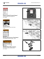
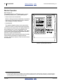
Operator Manual
4-, 6- and 8-Row
YP425A3P, YP625A3P & YP825A3P
3-Point Yield-Pro® Air Planters
®
with Air-Pro Seed Meters
Manufacturing, Inc.
www.greatplainsmfg.com
Read the operator manual entirely. When you see this symbol, the
subsequent instructions and warnings are serious - follow without
exception. Your life and the lives of others depend on it!
29997
Illustrations may show optional equipment not supplied with standard unit,
or may show similar pull-type models and their options.
EN
ORIGINAL INSTRUCTIONS
© Copyright 2015
Printed 2015-01-26
Table of Contents
Index
401-652M
401-652M
Table of Contents
Index
Table of Contents
Index
2015-01-26
Great Plains Manufacturing, Inc.
Table of Contents
Index
iii
Table of Contents
Important Safety Information ......................................1
Safety Decals .................................................................6
Introduction ................................................................10
Intended Usage ........................................................10
Document Family.....................................................10
Definitions.................................................................10
Models Covered ..........................................................10
Description of Unit ........................................................10
Using This Manual........................................................10
Owner Assistance ........................................................11
Preparation and Setup ...............................................12
Initial Setup...................................................................12
Post-Delivery/Seasonal Setup......................................12
Pre-Planting Setup .......................................................12
Hitching Tractor to Planter............................................13
Electrical Hookup......................................................13
Hydraulic Hose Hookup............................................14
Protect Motor Seals ..............................................16
Raise Parking Stands ...............................................17
Leveling Planter............................................................18
Monitor Setup ...............................................................19
Marker Setup (Option)..................................................19
Operating Instructions...............................................20
Pre-Start Checklist .......................................................20
Raising/Lowering Planter .............................................20
Transport ......................................................................21
Transport Steps ........................................................21
Typical Planter Weights............................................22
Loading Materials .........................................................23
Hopper Operations (s/n B1014R+)...........................23
Loading Seed (1.6 bu.hoppers) ................................23
Hopper Operations (s/n B1013R-)............................24
Loading Seed (1 bu.hoppers) ...................................24
Monitor Operation.........................................................26
Air System Operation ...................................................27
Air and Seeding System Overview ...........................28
Fan Circuit Operation (S/N-) ................................29
Fan Circuit Operation (S/N+) ...............................30
Fan General Operating Information......................31
Butterfly Valve Operation:.....................................31
Air-Pro® Meter Operation .............................................32
Meter Operation .......................................................32
Marker Operation (Option) S/N- ...................................33
Folding The Markers.................................................33
Marker Operation (Option) S/N+ ..................................34
Marker Controls ........................................................34
Field Set-Up Checklists ................................................35
Field Operation.............................................................36
Short-Term Parking ......................................................37
Long-Term Storage ......................................................37
Adjustments................................................................38
Setting Material Rates ..................................................39
Planting Rate Details ................................................39
1. Rate: Monitor configuration: .............................39
2015-01-26
2. Rate: Disk Selection: ........................................ 39
3. Rate: Range Sprockets .................................... 40
4. Rate: Transmission Sprockets ......................... 40
5. Rate: Seed Inlet Shutter ................................... 41
6. Rate: Meter Pressurization............................... 41
7. Rate: Checking................................................. 41
Marker Adjustments (Option) ....................................... 42
Marker Disk Adjustment ........................................... 42
Fan and Adjustment..................................................... 43
Furrow Check: ...................................................... 43
Fine-Tuning Meter Pressurization ............................ 44
Alternate Skip/Double Check ............................... 44
Gauge Wheel Adjustments .......................................... 45
Yoke Spring Adjustment........................................... 45
Wheel Axle Adjustment ............................................ 45
25AP Series Row Unit Adjustments............................. 46
Row Unit Down Pressure ......................................... 47
Adjusting Down-Force .......................................... 47
Unit-Mount Cleaner Adjustments ............................. 49
UMC Coulter Adjustments........................................ 50
UMC Coulter Depth Adjustment ........................... 50
Coulter Row Alignment ........................................ 51
Row-Unit Opener Disk Adjustments......................... 52
Setting Planting Depth ......................................... 52
Opener Disc Contact Region ............................... 52
Adjusting Disc Contact ......................................... 52
Side Gauge Wheel Adjustment ................................ 53
Adjusting Gauge Wheel Scrapers ........................ 54
Seed Meter Setup and Adjustment .......................... 55
Meter Rain Cover ................................................. 55
Seed Inlet Shutter Adjustment ............................. 55
Optimal Seed Pool Slopes ................................... 56
Meter Re-Fill......................................................... 56
Air-Pro® Meter Disk Installation ............................... 57
Removing a Seed Disk......................................... 58
Row Unit Shut-Off .................................................... 58
Sprocket Indexing (Stagger) ................................ 60
Seed Firmer Adjustments......................................... 61
Keeton Seed Firmer Adjustment .......................... 61
Seed-Lok® Seed Firmer Lock-Up......................... 61
Press Wheel Adjustment......................................... 62
Press Wheel Down Pressure ............................... 62
Press Wheel Stagger ........................................... 62
Press Wheel Centering ........................................ 63
Troubleshooting......................................................... 64
Planting Rate Problems ............................................... 64
Suggested Furrow Check:.................................... 64
Seed Pool Troubleshooting.......................................... 65
Magnehelic® Gauge Troubleshooting ...................... 66
Population Troubleshooting Charts.............................. 67
Maintenance and Lubrication ................................... 74
Maintenance ................................................................ 74
Material Clean-Out....................................................... 75
Funnel Conversion ............................................... 75
Seed Clean-Out (Container) ................................ 75
Seed Clean-Out (Funnel) ..................................... 75
Meter Clean-Out....................................................... 76
Table of Contents
Index
401-652M
iv
YP4-6-825A3P
Table of Contents
Alternate Meter Clean-Out ................................... 76
Meter Brush Maintenance............................................ 77
Meter Brush Replacement ....................................... 78
Seed Disk Maintenance ........................................... 79
Cleaning and Storing Seed Disks ........................ 79
Speed Sensor Gap ...................................................... 79
Air Box Residue Clean-Out.......................................... 80
Hydraulic Maintenance ................................................ 81
Bleeding Marker Hydraulics ..................................... 81
Drive-Line Shear Pin.................................................... 81
Marker Maintenance (Option) ...................................... 82
Marker Shear Bolt Replacement .............................. 82
Marker Grease Seal Cap ......................................... 82
Chain Maintenance ...................................................... 83
Meter Drive Chain .................................................... 83
Spreaders and Scrapers .............................................. 84
Row-Unit Side Wheels ................................................. 84
Seed Flap Replacement .............................................. 85
Lubrication ................................................................... 86
Seed Lubricants ........................................................... 90
Options ....................................................................... 91
Appendix A - Reference Information........................ 97
Specifications and Capacities ...................................... 97
401-652M
Index
Great Plains Manufacturing, Inc.
YP425A3P Single-Row Data ....................................97
YP425A3P Twin-Row Data.......................................98
YP625A3P Single-Row Data ....................................99
YP625A3P Twin-Row Data.....................................100
YP825A3P Single-Row Data ..................................101
YP825A3P Twin-Row Data.....................................102
Torque Values Chart ..................................................103
Tire Inflation Chart ......................................................103
Hydraulic Diagrams ....................................................104
Chain Routing.............................................................107
Appendix B - Pre-Delivery .......................................111
Appendix C - Initial Setup ........................................113
Post-Delivery Checklist...............................................113
Seed Monitor Console Installation..............................113
Initial Marker Setup (Option).......................................114
Marker Speed Adjustment ......................................114
Marker Extension....................................................115
Marker Extension Table ......................................116
122-278S Scraper Installation ....................................117
Warranty .....................................................................118
Index ..........................................................................119
Table of Contents
Index
2015-01-26
Great Plains Manufacturing, Inc.
Table of Contents
Index
1
Index
401-652M
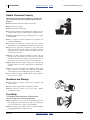
Important Safety Information
Look for Safety Symbol
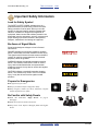
The SAFETY ALERT SYMBOL indicates there is a
potential hazard to personal safety involved and extra
safety precaution must be taken. When you see this
symbol, be alert and carefully read the message that
follows it. In addition to design and configuration of
equipment, hazard control and accident prevention are
dependent upon the awareness, concern, prudence and
proper training of personnel involved in the operation,
transport, maintenance and storage of equipment.
Be Aware of Signal Words
Signal words designate a degree or level of hazard
seriousness.
DANGER indicates an imminently hazardous situation
which, if not avoided, will result in death or serious injury.
This signal word is limited to the most extreme situations,
typically for machine components that, for functional
purposes, cannot be guarded.
WARNING indicates a potentially hazardous situation
which, if not avoided, could result in death or serious
injury, and includes hazards that are exposed when
guards are removed. It may also be used to alert against
unsafe practices.
CAUTION indicates a potentially hazardous situation
which, if not avoided, may result in minor or moderate
injury. It may also be used to alert against unsafe
practices.
Prepare for Emergencies
▲ Be prepared if a fire starts.
▲ Keep a first aid kit and fire extinguisher handy.
▲ Keep emergency numbers for doctor, ambulance, hospital
and fire department near phone.
Be Familiar with Safety Decals
▲ Read and understand “Safety Decals” on page 6,
thoroughly.
▲ Read all instructions noted on the decals.
▲ Keep decals clean. Replace damaged, faded and illegible
decals.
2015-01-26
Table of Contents
2
YP4-6-825A3P
Table of Contents
Index
Great Plains Manufacturing, Inc.
Index
2015-01-26
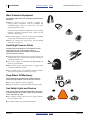
Wear Protective Equipment
Great Plains advises use of the following personal safety
equipment.
▲ Hearing protection, such as earmuffs or earplugs, for
making planter adjustments with the hydraulic fan
running.Prolonged exposure to loud noise can cause
hearing impairment or loss.
Avoid wearing entertainment headphones while operating
machinery. Operating equipment safely requires the full
attention of the operator.
▲ Face shield, goggles or full face respirator when handling
treated seed, seed lubricants or seed treatment.
▲ Gloves for working near sharp objects, and for handing
lubricants or treatments.
Avoid High Pressure Fluids
Escaping fluid under pressure can penetrate the skin,
causing serious injury. This planter requires a
Power-Beyond port, which is always under pressure
when the tractor is running.
▲ Avoid the hazard by relieving pressure at other remotes, and
shutting down tractor before connecting, disconnecting or
inspecting hydraulic lines.
▲ Use a piece of paper or cardboard, NOT BODY PARTS, to
check for suspected leaks.
▲ Wear protective gloves and safety glasses or goggles when
working with hydraulic systems.
▲ If an accident occurs, seek immediate medical assistance
from a physician familiar with this type of injury.
Keep Riders Off Machinery
Riders obstruct the operator’s view. Riders could be
struck by foreign objects or thrown from the machine.
▲ Never allow children to operate equipment.
▲ Keep all bystanders away from machine during operation.
Use Safety Lights and Devices
Slow-moving tractors and towed implements can create
a hazard when driven on public roads. They are difficult
to see, especially at night.
▲ Use flashing warning lights and turn signals whenever
driving on public roads.
▲ Use lights and devices provided with implement.
401-652M
Table of Contents
Great Plains Manufacturing, Inc.
Table of Contents
Index
Important Safety Information
3
Transport Machinery Safely
Maximum transport speed for implement is 20 mph (32
kph), 13 mph (22 kph) in turns. Some rough terrains
require a slower speed. Sudden braking can cause a
towed load to swerve and upset.
▲ Do not exceed 20 mph. Never travel at a speed which does
not allow adequate control of steering and stopping. Reduce
speed if towed load is not equipped with brakes.
▲ Comply with state and local laws.
▲ Do not tow an implement using a tractor with insufficient
ballast.
▲ Carry reflectors or flags to mark planter in case of
breakdown on the road.
▲ Keep clear of overhead power lines and other obstructions
when transporting. Refer to transport dimensions under
“Specifications and Capacities” on page 97.
▲ Do not fold or unfold the planter while the tractor is
moving.
2015-01-26
Table of Contents
Index
401-652M
4
YP4-6-825A3P
Table of Contents
Index
Great Plains Manufacturing, Inc.
Index
2015-01-26
Handle Chemicals Properly
Agricultural chemicals can be dangerous. Improper use
can seriously injure persons, animals, plants, soil and
property.
▲ Read and follow chemical supplier instructions.
▲ Wear protective clothing.
▲ Handle all chemicals with care.
▲ Agricultural chemicals can be dangerous. Improper use can
seriously injure persons, animals, plants, soil and property.
▲ Inhaling smoke from any type of chemical fire is a serious
health hazard.
▲ Store or dispose of unused chemicals as specified by the
chemical manufacturer.
▲ If chemical is swallowed, carefully follow the chemical
manufacturer’s recommendations and consult with a doctor.
▲ If persons are exposed to a chemical in a way that could
affect their health, consult a doctor immediately with the
chemical label or container in hand. Any delay could cause
serious illness or death.
▲ Dispose of empty chemical containers properly. By law
rinsing of the used chemical container must be repeated
three times. Puncture the container to prevent future use. An
alternative is to jet-rinse or pressure rinse the container.
▲ Wash hands and face before eating after working with
chemicals. Shower as soon as application is completed for
the day.
▲ Apply only with acceptable wind conditions. Wind speed
must be below 5 mph. Make sure wind drift of chemicals
will not affect any surrounding land, people or animals.
▲ Never wash out a hopper within 100 feet of any freshwater
source or in a car wash.
Shutdown and Storage
▲ Lower planter, put tractor in park, turn off engine, and
remove the key.
▲ Secure planter using blocks and supports provided.
▲ Detach and store planter in an area where children
normally do not play.
Tire Safety
Tire changing can be dangerous. Employ trained
personnel using correct tools and equipment.
▲ When inflating tires, use a clip-on chuck and extension hose
long enough for you to stand to one side–not in front of or
over tire assembly. Use a safety cage if available.
▲ When removing and installing wheels, use wheel-handling
equipment adequate for weight involved.
401-652M
Table of Contents
Great Plains Manufacturing, Inc.
Table of Contents
Index
Important Safety Information
5
Practice Safe Maintenance
▲ Understand procedure before doing work. Use proper
tools and equipment. Refer to this manual for additional
information.
▲ Work in a clean, dry area.
▲ Lower the planter, put tractor in park, turn off engine, and
remove key before performing maintenance.
▲ Make sure all moving parts have stopped and all system
pressure is relieved.
▲ Allow planter to cool completely.
▲ Disconnect battery ground cable (-) before servicing or
adjusting electrical systems or before welding on planter.
▲ Inspect all parts. Make sure parts are in good condition
and installed properly.
▲ Remove buildup of grease, oil or debris.
▲ Remove all tools and unused parts from planter before
operation.
Safety At All Times
Thoroughly read and understand the instructions in this
manual before operation. Read all instructions noted on
the safety decals.
▲ Be familiar with all planter functions.
▲ Operate machinery from the driver’s seat only.
▲ Do not leave planter unattended with tractor engine
running.
▲ Do not stand between the tractor and planter during
hitching.
▲ Keep hands, feet and clothing away from power-driven
parts.
▲ Wear snug-fitting clothing to avoid entanglement with
moving parts.
▲ Watch out for wires, trees, etc., when folding and raising
planter. Make sure all persons are clear of working area.
2015-01-26
Table of Contents
Index
401-652M
6
YP4-6-825A3P
Table of Contents
Index
Great Plains Manufacturing, Inc.
Safety Decals
Safety Reflectors and Decals
Your implement comes equipped with all lights, safety
reflectors and decals in place. They were designed to
help you safely operate your implement.
To install new decals:
▲ Read and follow decal directions.
2. Peel backing from decal. Press firmly on surface,
being careful not to cause air bubbles under decal.
▲ Keep lights in operating condition.
1. Clean the area on which the decal is to be placed.
▲ Keep all safety decals clean and legible.
▲ Replace all damaged or missing decals. Order new decals
from your Great Plains dealer. Refer to this section for
proper decal placement.
▲ When ordering new parts or components, also request
corresponding safety decals.
31026
818-055C
Slow Moving Vehicle Reflector
On the tube supporting meter pressurization manifold;
1 total
838-266C
Red Reflectors
On the back of end seed hoppers
(rear seed hoppers on twin-row planters)
and on the back of the inner marker arm (option),
above daytime reflector:
2 or 4 total
31003
401-652M
Table of Contents
Index
2015-01-26
Great Plains Manufacturing, Inc.
Table of Contents
Index
Important Safety Information
7
838-265C
Amber Reflectors
On the front face of the front tool bar, each end,
on the outside of the end hopper supports
4 total
31003
838-267C
Daytime Reflectors
On the back of two center seed hoppers
(rear seed hoppers on twin-row planters) and
on the back of the inner marker arm (option),
below red reflector:
2 or 4 total
31003
2015-01-26
Table of Contents
Index
401-652M
8
YP4-6-825A3P
Table of Contents
Index
Great Plains Manufacturing, Inc.
818-323C
Danger: Possible Chemical Hazard
On the underside of each hopper lid;
4 to 16 total
29998
818-337C
Warning: Speed
On front of main tool bar to left of hitch;
1 total
31003
818-339C
Warning: High Pressure Fluid Hazard
On right face of 3-point top hitch; 1 total
31003
WARNING
SHARP OBJECT HAZARD
To prevent serious injury or Death from Sharp Objects:
Keep hands, feet, hair, & clothing away from tines.
DO NOT stand or climb on machine when operating.
Keep others away.
818-525C
818-525C
Warning: Sharp Object (Option)
Front face of each row cleaner frame;
4 to 12 total
27333
401-652M
Table of Contents
Index
2015-01-26
Great Plains Manufacturing, Inc.
Table of Contents
Index
Important Safety Information
9
818-682C
Warning: Markers (Option)
On front face of inner marker arm;
2 total
31003
818-587C
Caution: Read Operator’s Manual
On right face of 3-point top hitch; 1 total
29960
CAUTION
To Avoid Injury or Machine Damage from Improper Tire
Inflation or Torquing of Wheel Bolts:
Maximum inflation pressure of tires is 90 psi.
Torque wheel bolts to 120 lb-ft.
838-595C
838-595C
Caution: Tire Pressure and Bolt Torque
on valve stem side of each wheel;
2 or 4 total
2015-01-26
29880
Table of Contents
Index
401-652M
10
YP4-6-825A3P
Table of Contents
Index
Great Plains Manufacturing, Inc.
Introduction
Great Plains welcomes you to its growing family of new
product owners. The 4-, 6- and 8-Row 3-Point Yield-Pro®
Air Planter (YP425A3P, YP625A3P & YP825A3P) has
been designed with care and built by skilled workers
using quality materials. Proper setup, maintenance, and
safe operating practices will help you get years of
satisfactory use from the machine.
U
F
Models Covered
YP425A3P-0430
YP425A3P-08TR
YP425A3P-0836
YP425A3P-0838
YP425A3P-0840
YP425A3P-0470
YP625A3P-0630
YP625A3P-12TR
YP625A3P-1236
YP625A3P-1238
YP625A3P-1240
YP625A3P-0670
YP825A3P-0830
YP825A3P-16TR
YP825A3P-1636
YP825A3P-1638
YP825A3P-1640
YP825A3P-0870
4-Row, 30-inch
8-Row (4-Pair), 30-inch Twin-Row
8-Row (4-Pair), 36-inch Twin-Row
8-Row (4-Pair), 38-inch Twin-Row
8-Row (4-Pair), 40-inch Twin-Row
4-Row, 70 cm
6-Row, 30-inch
12-Row (6-Pair), 30-inch Twin-Row
12-Row (6-Pair), 36-inch Twin-Row
12-Row (6-Pair), 38-inch Twin-Row
12-Row (6-Pair), 40-inch Twin-Row
6-Row, 70 cm
8-Row, 30-inch
16-Row (8-Pair), 30-inch Twin-Row
16-Row (8-Pair), 36-inch Twin-Row
16-Row (8-Pair), 38-inch Twin-Row
16-Row (8-Pair), 40-inch Twin-Row
8-Row, 70 cm
Note: YP425A, YP625A and YP825A pull-type models
have a separate Operator manual (401-651M).
Description of Unit
The YP4-6-825A3P Planter is a three-point precision
planting implement for use in conventional till,
minimum-till, or light no-till conditions. The
YP4-6-825A3P accepts unit-mounted coulters and/or
row cleaners. Coulters make it suitable for light to
moderate no-till conditions only. The YP4-6-825A3P
includes 25AP Series openers with Air-Pro® meters
supporting a wide choice of seed disks.
Using This Manual
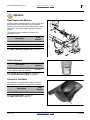
L
D
R
L
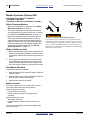
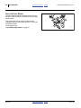
Figure 1
YP425A3P/625A3P/825A3P Planter
29997
Intended Usage
Use the YP4-6-825A3P Planter to seed
production-agriculture crops only. Do not modify the
planter for use with attachments other than Great Plains
options and accessories specified for use with the
YP4-6-825A3P.
Document Family
401-652M
401-651B
401-652P
11001-1333
Owner’s Manual (this document)
Seed and Fertilizer Rate manual
Parts manual
DICKEY-john® PM300 manual
Definitions
The following terms are used throughout this manual.
A crucial point of information related to the preceding topic.
Read and follow the directions to remain safe, avoid serious
damage to equipment and ensure desired field results.
Note: Useful information related to the preceding topic.
This manual will familiarize you with safety, assembly,
operation, adjustments, troubleshooting, and
maintenance. Read this manual and follow the
recommendations to help ensure safe and efficient
operation.
The information in this manual is current at printing.
Some parts may change to assure top performance.
401-652M
B
R
Right-hand and left-hand as used in
this manual are determined by facing
the direction the machine will travel
while in use unless otherwise stated.
An orientation rose in some line art
illustrations shows the directions of:
Up, Back, Left, Down, Front, Right.
Table of Contents
Index
U
B
R
F
D
L
2015-01-26
Great Plains Manufacturing, Inc.
Table of Contents
Index
Introduction
11
Owner Assistance
If you need customer service or repair parts, contact a
Great Plains dealer. They have trained personnel, repair
parts and equipment specially designed for Great Plains
products.
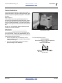
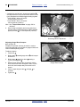
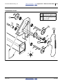
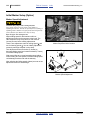
Refer to Figure 2
Your machine’s parts were specially designed and
should only be replaced with Great Plains parts. Always
use the serial and model number when ordering parts
from your Great Plains dealer. The serial-number plate is
located on the right end of the rear face of the main tool
bar.
Record your YP4-6-825A3P Planter model and serial
number here for quick reference:
Model Number:__________________________
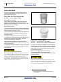
Figure 2
Serial Number Plate
Serial Number: __________________________
31027
Your Great Plains dealer wants you to be satisfied with
your new machine. If you do not understand any part of
this manual or are not satisfied with the service received,
please take the following actions.
1. Discuss the matter with your dealership service
manager. Make sure they are aware of any problems
so they can assist you.
For further assistance write to:
2. If you are still unsatisfied, seek out the owner or
general manager of the dealership.
Product Support
Great Plains Mfg. Inc., Service Department
PO Box 5060
Salina, KS 67402-5060
785-823-3276
2015-01-26
Table of Contents
Index
401-652M
12
YP4-6-825A3P
Table of Contents
Index
Great Plains Manufacturing, Inc.
Index
2015-01-26
Preparation and Setup
This section helps you prepare your tractor and
YP425A3P, YP625A3P & YP825A3P Planter for use, and
covers tasks that need to be done seasonally, or when
the tractor/planter configuration changes.
Before using the planter in the field, you must hitch it to a
suitable tractor, inspect systems and level the planter.
Before using the planter for the first time, and periodically
thereafter, certain adjustments and calibrations are
required.
Initial Setup
See “Appendix B - Pre-Delivery” on page 111 for
pre-delivery items (normally completed by dealer), and
first-time/infrequent setup tasks, including:
• Install seed monitor console in tractor (page 113).
• Set marker extension (Option, page 115).
• Install any Options not factory- or dealer-installed.
Post-Delivery/Seasonal Setup
On initial delivery, use with a new tractor, and seasonally,
check and as necessary, complete these items before
continuing to the routine setup items:
• Bleed hydraulic system (page 81).
Pre-Planting Setup
Complete this checklist before routine setup:
❑
Read and understand “Important Safety
Information” on page 1.
❑
Check that all working parts are moving freely, bolts
are tight, and cotter pins are spread.
❑
Check that all grease fittings are in place and
lubricated. See “Lubrication” on page 86.
❑
Check that all safety decals and reflectors are
correctly located and legible. Replace if damaged.
See “Safety Decals” on page 6.
❑
Inflate tires to pressure recommended and tighten
wheel bolts as specified. See “Torque Values
Chart” on page 103.
401-652M
Table of Contents
Great Plains Manufacturing, Inc.
Table of Contents
Index
Preparation and Setup
13
Hitching Tractor to Planter
Crushing Hazard:
Do not stand or place any body part between planter and
moving tractor. You may be severely injured or killed by being
crushed between the tractor and planter. Stop tractor engine
and set parking brake before attaching cables and hoses.
1. To prevent soil compaction on rows, set tractor
wheels at 60 inches center-to-center. For hillsides
and steep slopes, set tractor wheels as wide as
possible for maximum stability.
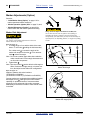
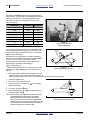
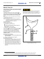
3
2. Adjust tractor lower links to maximize lifting height.
3. Set tractor sway blocks to minimize side sway. Set
tractor hitch lift control to Float.
4. Back tractor up to planter. Align lower links with the
lower hitch clevis on planter. Adjust hitch bushings 1
and spacers 2 supplied with planter according to the
category of your tractor. Lock pins in place.
5. Attach tractor top link to upper hitch clevis on planter.
• For Category II tractors, hitch tractor top link to
lower hole pair 3 in planter clevis.
• For Category II quick couplers and Category III
tractors, hitch tractor top link to center hole pair in
planter clevis.
1
2
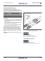
Figure 3
Three Point Hitch
31048
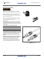
Figure 4
Connector Identification
25236
31033
Electrical Hookup
Refer to Figure 4
Your planter is equipped with systems that require
separate electrical connections. For future reference,
note any optional connectors on this checklist.
❑
1
Lighting connector (standard)
❑
2
Monitor connector (standard)
❑
__________________________
❑
__________________________
1
2
Make sure tractor is shut down with accessory power off
before making connections.
These connections may be made in any order. The key
requirement is that all connections be made prior to
planter movement.
2015-01-26
Table of Contents
Index
401-652M
14
YP4-6-825A3P
Table of Contents
Index
Great Plains Manufacturing, Inc.
Hydraulic Hose Hookup
High Pressure Fluid Hazard:
Shut down tractor before making hydraulic connections.
Only trained personnel should work with system hydraulics.
Escaping fluid under pressure can have sufficient pressure to
penetrate the skin causing serious injury. If an accident
occurs, seek immediate medical assistance from a physician
familiar with this type of injury.
Use paper or cardboard, NOT BODY PARTS, to check for
leaks. Wear protective gloves and safety glasses or goggles
when working with hydraulic systems.
Refer to Figure 5
Great Plains hydraulic hoses have color coded handle
grips to help you hookup hoses to your tractor outlets.
Hoses that go to the same remote valve are marked with
the same color.
Current Style Color Coded Hose Handles
Color
Hydraulic Function
Green
Marker
Black
Fan
To distinguish hoses on the same hydraulic circuit, refer
to the symbol molded into the handle grip. Hoses with an
extended-cylinder symbol feed cylinder base ends.
Hoses with a retracted-cylinder symbol feeds cylinder
rod ends.
For hydraulic fan and drive motors, connect the hose
under the retracted cylinder symbol to the pressure side
of the motor. Connect the hose under the extended
cylinder symbol to the return side of the motor.
The fan motor further requires hookup of a third line,
which returns hydraulic fluid from the fan motor case.
Figure 5
Color Coded Hose Handles
401-652M
Table of Contents
Index
31733
2015-01-26
Great Plains Manufacturing, Inc.
Table of Contents
Index
Preparation and Setup
15
Older Style Hoses with Color Ties
Refer to Figure 6 and Figure 7 on page 16
Hydraulic hoses are color coded to help you hookup
hoses to your tractor outlets. Hoses that go to the same
remote valve are marked with the same color tie.
Color
Hydraulic Function
Orange
Marker
White
Fan
To distinguish hoses on the same hydraulic circuit, refer
to hose label.
• The fan motor case drain line is a separate hose with
no label plate. This hose is always connected first and
disconnected last.
• The hose under an extended-cylinder symbol feeds a
cylinder base end or motor return line.
• The hose under a retracted-cylinder symbol feeds a
cylinder rod end, or motor pressure line.
Secure hoses and cables so that they have sufficient
slack for hitch movements, but cannot get caught
between moving parts of planter. Failure to safely route
and secure hoses and cables could result in damage
requiring component repair/replacement, and lost field
time.
Figure 6
Older Style Hoses with Label
27270
Make connections in a specific order, described on the
next page.
Motor Seal Damage Risk:
Case Drain Hose must be attached first,
prior to inlet and return hoses being connected.
Case Drain Hose must be detached last,
to prevent damage to the fan motor.
Hydraulic Motor Performance Risk:
DO NOT hook case drain line to a “power-beyond port”.
2015-01-26
Table of Contents
Index
401-652M
16
YP4-6-825A3P
Table of Contents
Index
Great Plains Manufacturing, Inc.
Protect Motor Seals
Applies to planters with serial numbers:
(YP3P425A s/n B1004M-)
(YP3P625A s/n B1006P-) (YP3P825A s/n B1007R-)
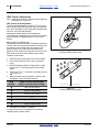
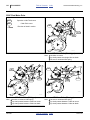
1. Connect the fan case drain line 1 first, before
making any other connections. Connect this line to a
low pressure drain port.
Note: Case drain hose has the smaller 1⁄4 inch I.D. hose
and small, flat-face, low-seep connector.
2. Connect the fan return
2
line second.
Note: Fan pressure return hose has a large (1.06 inch/
2.7 cm diameter) quick coupler.
3. Connect the fan motor pressure hose 3 third. If the
tractor has a priority remote, use it for the fan
connection.
4. Make marker (option) connections.
Machine Damage Risk:
DO NOT connect the fan case drain line to a
power-beyond-port. Case Drain Hose must be attached first,
prior to inlet and return hoses being connected. Case Drain
Hose must be detached last, to prevent damage to the fan
motor.
3
2
1
Figure 7
Fan Hoses (S/N-)
29781
Applies to planters with serial numbers:
(YP3P425A s/n B1005M+)
(YP3P625A s/n B1007P+) (YP3P825A s/n B1008R+)
For complete instructions see “Fan Circuit Operation
(S/N+)” on page 30.
1. Connect the motor return line 3 , to remote circuit
return (Extend port) or to sump.
3
2. Connect the motor inlet line 4 to a tractor remote
capable of 20 liters per minute. If a priority remote is
available, use it for the fan.
4
Figure 8
Fan Hoses (S/N+)
401-652M
Table of Contents
Index
31886
2015-01-26
Table of Contents
Great Plains Manufacturing, Inc.
Index
Preparation and Setup
17
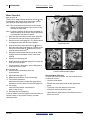
Raise Parking Stands
Refer to Figure 3
3. Use tractor hitch circuit to raise planter slightly off
parking stands.
4. Remove hairpin and cross-pin
1.
5. Slide stand tube up until lower storage hole
with bracket hole.
2
aligns
6. Insert cross-pin and secure with hairpin.
7. Repeat for other side of planter.
1
2
Figure 9
Parking Stand
2015-01-26
Table of Contents
Index
31049
401-652M
18
YP4-6-825A3P
Table of Contents
Index
Great Plains Manufacturing, Inc.
Leveling Planter
For row units to function correctly, planter must be:
• level from side to side,
• level from front to back, and;
• at correct tool bar height.
Perform this setup on level ground in representative field
conditions.
1
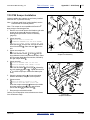
Refer to Figure 10
1. Raise planter so that gauge wheels are just off
ground.
2. At each gauge wheel, measure the pre-compressed,
no-load length of the yoke spring 1 .
All axles should be in the same (upper or lower) arm
holes. All springs should have this same length. Note
this length for step 9.
See page 45 for factory setting, and adjustments for
local conditions.
3. Check tire pressures of gauge wheels. As
necessary, inflate to specifications (page 103).
Figure 10
Gauge Wheel Yoke
31053
Figure 11
Tool Bar Height and Leveling
31051
Refer to Figure 11
4. Measure height 2 from bottom of main tool bar to
ground, at each end. If this dimension differs by
more than 1⁄2 inch (6.4 mm) at each end, adjust
lower links of tractor to level side-to-side.
Note the current height for step 7, and what lowering
would be required to make that 26 inch (66 cm).
5. Check front-to-back level at top of main tool bar. If
unlevel, adjust top of tractor three-point to level.
6. Pull forward slowly, and lower the planter to
approximately 26 inch (66 cm). Stop the tractor and
set the parking brake.
2
7. Check the tool bar height 2 . Adjust the hitch height
until it is 26 inch. If available, set a hitch stop control
to capture this height.
8. Check that the row units are running level with the
ground.
9. Check that the gauge wheels are all in solid ground
contact, tires slightly compressed, and that the
springs are slightly compressed from the length
checked at step 2.
Hitch configuration during planting can vary between
tractor models, and due to field conditions. Great Plains
recommends starting with the hitch set to Float or
Position/Depth Control (and not Load or Draft Control).
401-652M
Table of Contents
Index
2015-01-26
Great Plains Manufacturing, Inc.
Table of Contents
Index
Preparation and Setup
19
Monitor Setup
Refer to Figure 19
The standard DICKEY-john® PM300 system monitors
the following elements of a YP4-6-825A3P planter:
• Seeds at each row unit seed tube.
• Ground speed.
See “Seed Monitor Console Installation” on page 113.
Refer to the DICKEY-john® PM300/PM332/PM400
Operator’s Manual for monitor operations.
After installation, and prior to first field use, the monitor
must be setup with the row spacing and speed sensor
constant, as well as your preferences for information
display. Row count is auto-assigned, but any other
factory defaults are not likely to be correct for your
planter.
Row spacing data may be found in the Appendix.
For speed setup, Great Plains recommends using the
400-foot calibration described in the DICKEY-john®
manual, rather than using a theoretical “# of pulses”.
Perform the calibration run in representative field
conditions, as soil conditions, surface looseness and
other tillage practices can cause variations in the
effective rolling radius of the ground drive wheel.
Prior to each planting session, set any desired limits for
speed and population for the current crop.
Figure 12
Monitor Primary Screen
29971
Marker Setup (Option)
Prior to first use, check and adjust:
• “Marker Speed Adjustment” on page 114.
Prior to first use, and whenever changing row spacings,
set or reset:
• “Marker Extension” on page 115.
Prior to each planting session, check and adjust:
• “Marker Disk Adjustment” on page 42.
2015-01-26
Table of Contents
Index
401-652M
20
YP4-6-825A3P
Table of Contents
Index
Great Plains Manufacturing, Inc.
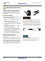
Operating Instructions
This section covers general operating procedures.
Experience, machine familiarity, and the following
information will lead to efficient operation and good
working habits. Always operate farm machinery with
safety in mind.
Pre-Start Checklist
Perform the following steps before transporting the
YP4-6-825A3P planter to the field.
❑
Carefully read “Important Safety Information” on
page 1.
❑
Install seed disks appropriate for crop. See
“Air-Pro® Meter Disk Installation” on page 57.
❑
Lubricate planter as indicated under “Lubrication”
on page 86.
❑
Check all tires for proper inflation. See “Torque
Values Chart” on page 103.
❑
Check all bolts, pins, and fasteners. Torque as
shown in “Torque Values Chart” on page 103.
❑
Check planter for worn or damaged parts. Repair or
replace parts before going to the field.
❑
Check hydraulic hoses, fittings, and cylinders for
leaks. Repair or replace before going to the field.
High Pressure Fluid Hazard:
Relieve pressure and shut down tractor before connecting,
disconnecting or checking hydraulic lines. Use a piece of
paper or cardboard, NOT BODY PARTS, to check for leaks.
Wear protective gloves and safety glasses or goggles when
working with hydraulic systems. Escaping fluid under pressure
can have sufficient pressure to penetrate the skin causing
serious injury. If an accident occurs, seek immediate medical
assistance from a physician familiar with this type of injury.
Raising/Lowering Planter
The planter is raised and lowered using the tractor
3-point hitch.
In field conditions, drive forward while lowering openers
into ground. Never back up with openers in ground.
Hitch configuration during planting can vary between
tractor models, and due to field conditions. Great Plains
recommends starting with the hitch set to Float or
Position/Depth Control (and not Load or Draft Control).
401-652M
Machine Damage Risks:
Always fold markers (page 33) before raising or lowering.
Always raise the planter for any reverse/backing.
Except on pavement, begin forward motion before lowering, as
rows move backward slightly as arms swing up.
Table of Contents
Index
2015-01-26
Great Plains Manufacturing, Inc.
Table of Contents
Index
Operating Instructions
21
Transport
Loss of Control Hazard:
Do not transport with insufficient ballast or with an
inadequate tractor.
Check that your tractor has enough ballast for the weight of
the drill. A tractor with insufficient ballast has insufficient
traction at the front wheels, causing loss of control, leading to
a serious road accident, injury or death. Refer to your tractor
operator manual for ballast requirements.
Check that tractor is rated for the fully-ballasted load. An
inadequate tractor may be damaged by over-loading. It is also
at risk for loss of control in turns and braking, leading to a
serious road accident, injury or death.
Braking and Loss of Control Hazard:
Do not exceed 20 mph (32 kph).
The planter can weigh nearly 11,000 pounds (5000 kg),
depending on configuration and seed load. The tractor
MUST be rated and ballasted for the load. Do not tow if
planter exceeds the load rating of the vehicle. See tables
on next page for typical configuration weights.
Transport Steps
Transport only with markers stowed (page 33).
1. Check that planter is securely hitched to a sufficient
tractor (page 13).
2. Verify correct operation of lights.
3. Fold markers if unfolded (Option, page 33).
4. Raise planter (page 20).
Increased Hazards and Wear Risks:
Seed may be loaded prior to travel, but increases stopping
distance, increases the need for caution in turns and braking,
and increases tire wear.
5. If any seed is in hoppers or delivery hoses, close
seed inlet shutters at meters (page 58).
6. Plan the route. Avoid steep hills.
7. Always have lights on for highway operation.
8. Do not exceed 32 kph (20 mph). Comply with all
national, regional and local laws when traveling on
public roads.
9. Remember that the planter may be wider than the
tractor. Allow safe clearance.
10. Transport slowly over uneven or rough terrain.
2015-01-26
Table of Contents
Index
401-652M
22
YP4-6-825A3P
Table of Contents
Index
Great Plains Manufacturing, Inc.
Typical Planter Weights
Approximate Weights of
Representative
Configurations
-0470
-0430
-08TR
YP425A3P-0436
-0836
-0438
-0838
-0440
-0840
Base Planter
1500 kg
3300 lb
4600 lb
3000 lb
4800 lb
3000 lb
4800 lb
3600 lb
4800 lb
Typical¹ Empty
1600 kg
3500 lb
4900 lb
3100 lb
5100 lb
3100 lb
5100 lb
3700 lb
5100 lb
Typical¹ Full
1700 kg
3800 lb
5500 lb
3400 lb
5700 lb
3400 lb
5700 lb
4000 lb
5700 lb
Maximum² Empty
1900 kg
4200 lb
5800 lb
3900 lb
6000 lb
3900 lb
6000 lb
4500 lb
6100 lb
Maximum² Full
2100 kg
4500 lb
6500 lb
4200 lb 6700 lb 4200 lb 6700 lb 4800 lb 6700 lb
Note: Weight of a specific planter can vary by hundreds of
pounds, depending on installed options and
material loaded.
Center of Gravity is approximately 36in aft of hitch.
1. Typical: UM Coulters. No Markers or Row Cleaners.
2. Maximum: UMC+RC, Markers.
Approximate Weights of
Representative
Configurations
-0670
-0630
-12TR
-0636
YP625A3P-1236
-0638
-1238
-0640
-1240
Base Planter
2000 kg
4300 lb
6200 lb
4200 lb
6100 lb
4200 lb
6100 lb
4200 lb
6100 lb
Typical¹ Empty
2100 kg
4500 lb
6600 lb
4500 lb
6500 lb
4500 lb
6500 lb
4500 lb
6500 lb
Typical¹ Full
2300 kg
5000 lb
7500 lb
4900 lb
7500 lb
4900 lb
7500 lb
4900 lb
7500 lb
Maximum² Empty
2500 kg
5400 lb
7800 lb
5300 lb
7700 lb
5300 lb
7700 lb
5300 lb
7700 lb
Maximum² Full
2700 kg
5900 lb
8700 lb
5800 lb 8700 lb 5800 lb 8700 lb 5800 lb 8700 lb
Note: Weight of a specific planter can vary by hundreds of
pounds, depending on installed options and
material loaded.
Center of Gravity is approximately 0in aft of hitch.
1. Typical: UM Coulters. No Markers or Row Cleaners.
2. Maximum: UMC+RC, Markers.
Approximate Weights of
Representative
Configurations
-0870
-0830
-16TR
YP825A3P-0836
-1636
-0838
-1638
-0840
-1640
Base Planter
2300 kg
5000 lb
7400 lb
5500 lb
8000 lb
5500 lb
8000 lb
5500 lb
8000 lb
Typical¹ Empty
2300 kg
5300 lb
8100 lb
5800 lb
8600 lb
5800 lb
8600 lb
5800 lb
8600 lb
Typical¹ Full
2600 kg
5900 lb
9300 lb
6400 lb
9800 lb
6400 lb
9800 lb
6400 lb
9800 lb
Maximum² Empty
2800 kg
6300 lb
9500 lb
6900 lb
10100 lb
6900 lb
10100 lb
6900 lb
10100 lb
Maximum² Full
3100 kg
6900 lb
10700 lb
7500 lb 11300 lb 7500 lb 11300 lb 7500 lb 11300 lb
Note: Weight of a specific planter can vary by hundreds of
pounds, depending on installed options and
material loaded.
Center of Gravity is approximately 0in aft of hitch.
1. Typical: UM Coulters. No Markers or Row Cleaners.
2. Maximum: UMC+RC, Markers.
401-652M
Table of Contents
Index
2015-01-26
Great Plains Manufacturing, Inc.
Table of Contents
Index
Operating Instructions
Loading Materials
23
2
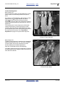
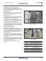
Hopper Operations (s/n B1014R+)
Refer to Figure 15 and Figure 16
Hopper lids 1 :
• the lids have two spring clips, one at each end
3.
1
3
• there is a molded handle at the rear end 2 of the
hopper lid (although the lid is reversible).
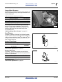
Figure 13
Hopper Lid
To open a hopper:
32446
1. Grasp the handle and snap lid off.
2. Park the lid lengthwise on the side lip of the hopper,
using the hooked ends of each spring clip inside the
lid (see Figure 18 on page 25).
1
The seed hoppers themselves are designed to be
removed, but are not removed for routine operations.
2
Loading Seed (1.6 bu.hoppers)
3. Install correct seed disks (page 57).
4. Check that each hopper is correctly seated and
secured:
4 front and rear mounting bolts secured
5 hopper discharge opening lined up with
6 seed tube
5. Open hopper lid
1.
6. Inspect the hopper for leftover seed and debris.
Clean out anything other than the seed to be
planted. See “Material Clean-Out” on page 75.
4
5
4
6
U
B
R
F
D
L
Figure 14
Air-Pro® Row Hopper
(serial number B1014R+)
2015-01-26
Table of Contents
Index
32233
401-652M
24
YP4-6-825A3P
Table of Contents
Index
Great Plains Manufacturing, Inc.
Loading Materials
Hopper Operations (s/n B1013R-)
3
Refer to Figure 15 and Figure 16
Hopper lids 1 have distinct ends:
• the hinge end 3 (with two lugs) mates with the front
end of the hopper.
1
• the latch end 2 (with a single lug) mates with the rear
end of the hopper.
Figure 15
Hopper Lid Hinge Lugs
28131
To open a hopper:
1. Pull the rear of the lid edge to the rear.
2. Swing the lid up at rear.
2
1
3. Disengage the lid at the front lugs.
4. Park the lid on the front lip of the hopper, using the
hook-plate feature inside the lid (see Figure 17 on
page 25).
The seed hoppers themselves are designed to be
removed, but are not removed for routine operations.
Loading Seed (1 bu.hoppers)
5. Install correct seed disks (page 57).
7
6. Close all seed inlet shutters (page 58).
7. Check that each hopper is correctly seated and
secured:
4 pivot hooks engage at front,
5 latch engaged at rear,
6 seed hose secured to
7 discharge weldment with
8 clamp.
4
9
8 5
8. The hopper slide gate 9 may be left open (by pulling
back), and doing so slightly increases seed capacity.
Note: If slide gate is open for seed loading, seed inlet
shutters must be closed unless the planter is
already at the field. Transporting with both gates
and shutters open can plug meters.
9. Open hopper lid
U
B
R
F
1.
D
10. Inspect the hopper for leftover seed and debris.
Clean out anything other than the seed to be
planted. See “Material Clean-Out” on page 75.
401-652M
Table of Contents
6
L
Figure 16
Air-Pro® Row Hopper
(serial number B1013R-)
Index
29975
2015-01-26
Great Plains Manufacturing, Inc.
Table of Contents
Index
Operating Instructions
25
Loading Seed, continued
Possible Agricultural Chemical Hazards:
Read and follow all supplier cautions for safe handling of
treated seed.
Irritant and Chronic Exposure Hazards:
Do not mix lubricants into seed with hands or any part of
body. Wear protective equipment. Use tools. See page 90.
11. Pre-mix seed and lubricant. For clean seeds other
than milo, cotton, and sunflowers sprinkle 1⁄4 cup of
Ezee Glide Plus per bushel or unit (60 ml per
35 liters) of seed.
For milo, cotton, and sunflowers double the
application to 1⁄2 cup (or more) per bu.or unit (120 ml
per 35 liters) of seed.
Figure 17
Adding Seed Lubricant
1 bu.Hoppers
(serial number B1013R-)
29976
Figure 18
1.6 bu.Hoppers
(serial number B1014R+)
32447
Population Risk:
The seed must be properly lubricated, starting with the first
seed through the meter. If unable to pre-mix prior to loading,
pre-mix at least one gallon (4 liters) per hopper, and load this
seed first. Fill the hoppers to half full with fresh seed. Add half
the lubricant and stir. Complete filling the hoppers and
sprinkle the remaining lubricant on top.
12. Add seed and lubricant to hoppers.
Refer to Figure 13 and Figure 14 on page 23
For 1.6 bu.hoppers (s/n B1014R+)
13. Close lids. Position front end of lid over front end lip
of hopper. Snap lid firmly in place.
Refer to Figure 15 and Figure 16 on page 24
For 1 bu.hoppers (s/n B1013R-)
14. Close lids. With lid tilted up at a slight angle, hook
the two front hinge lugs under the front hopper lip.
Swing down, keeping fingers clear of lug, and latch
the single rear lid lug on rear hopper lip.
Equipment Loss Risk:
Check that all 3 lid lugs are completely under the hopper lip,
or the lid may come off in transport.
2015-01-26
Table of Contents
Index
401-652M
26
YP4-6-825A3P
Table of Contents
Index
Great Plains Manufacturing, Inc.
Monitor Operation
Refer to Figure 19
The standard DICKEY-john® PM300 system monitors
the following elements of a YP4-6-825A3P planter:
• Seeds at each row unit seed tube:
Medium and larger seeds are individually counted with
high accuracy. Small seed sensing may be limited to
seed stoppage (“blockage”) detection.
• Ground speed:
The standard magnetic pickupa at the ground drive
allows the monitor to calculate and report population.
Once setup for the planter and your display preferences,
and configured for the current crop rates/limits, the
monitor is typically used in the “OPERATE” mode. Refer
to the DICKEY-john® PM300/PM332/PM400 Operator’s
Manual for monitor operation details.
Both the DICKEY-john® manual and this manual contain
trouble-shooting information for apparent monitor
problems. Check both manuals, as the focus and content
is not identical.
Figure 19
Monitor: Typical Operate Screen
29972
a. An optional radar speed sensor is available, as are Y-cables to accept input from an existing radar on the tractor. The magnetic pickup
may be preferred, as both speed and seed flow fall to zero at lift. With radar, the monitor cannot tell that seeding should have stopped.
You may experience more nuisance alarms with radar.
401-652M
Table of Contents
Index
2015-01-26
Table of Contents
Great Plains Manufacturing, Inc.
Index
Operating Instructions
27
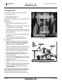
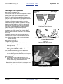
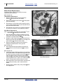
Air System Operation
U
B
R
1
F
D
L
2
5
17
3
6
16
7
8
9
4
15
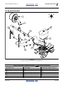
Figure 20
Planter Air System for Air-Pro® Seed Metering
Meter Pressurization System Elements (
Hydraulic Fan
7
2
Butterfly Valve
8 Air-Pro®
3
Meter Pressurization Air
9
4
Row Pressurizing Tube
5
6
1
shows air direction)
13
Seed Tube Sensor (Figure 21)
14
Sensor Port (Figure 21)
Seed Inlet Shutter
15
Pressure Sensor Lines
10
Seed Pool (Figure 21)
16
Pressure Sensor Chamber
Seed Hopper
11
Disk Seed Pocket (Cell)
17
Magnehelic® Pressure Gauge
Slide Gate
12
Seed Hose (Figure 21)
2015-01-26
Seed Hose
29973
Seed Meter
Table of Contents
Index
401-652M
28
YP4-6-825A3P
Table of Contents
Index
Great Plains Manufacturing, Inc.
Air and Seeding System Overview
8
Refer to Figure 20, on page 27, and Figure 21.
The hydraulic fan 1 supplies air exclusively for meter
operation. Fan rpm is operator-adjusted (page 31),
normally via the tractor circuit’s hydraulic flow control.
4
A manually-adjusted butterfly valve 2 is provided at the
fan outlet. See page 31 for valve adjustment.
The manifold system 3 delivers fan air across the
planter. It includes passive internal design features to
balance pressure across the planter.
Separate pressurization tubes
each row unit.
4
route manifold air to
14
11
Seed is delivered from the seed box 5 by gravity
through the sliding seed tubes 7 , to the inlet of the
Air-Pro® seed meter 8 .
A manually adjusted inlet shutter 9 controls the size of
the seed pool 10 at the base of the meter. The shutter
also minimizes air loss back up the seed inlet tube, and
is also used during row shut off. See page 55 for shutter
adjustments.
9
10
At the meter, pressurization air exits the meter through
the seed pockets 11 of the disk, and holds seed in the
pockets until released above the seed tube 12 .
12
In the seed tube, the seed sensor 13 detects passage of
seeds. Medium size and large seeds are counted
individually. With smaller seeds, most are detected,
allowing the monitor to detect stoppages.
13
Several rows have a pressure sensor port 14 for the
meter pressurization system. A line 15 from each of
these rows is connected to a chamber 16 to average the
pressures.
The averaged pressure is reported by a Magnehelic®
gauge 17 visible to the tractor operator. See page 43 for
use of the gauge in making fan adjustments.
A sensor 13 in each seed tube reports seed passage to
the seed monitor. Larger seeds are counted individually.
For smaller seeds, the system acts as a blockage
monitor.
Figure 21
Air-Pro® Meter, Disk Side
Note: Use of the special blank disk (page 59), and closing
the seed inlet shutter (page 55), are particularly
important when a sensor row is shut off.
31040
Note: On any row, running a normal disk with no seed, or
with an open empty inlet, unbalances the air
system. Doing either at a sensor row causes the
gauge to mis-report as well.
Note: Do not operate in the ground with the fan shut off, or
with insufficient manifold pressure. The meters will
completely fill with seed. Meter clean-out may be
required to resume normal operation.
401-652M
Table of Contents
Index
2015-01-26
Table of Contents
Great Plains Manufacturing, Inc.
Index
Operating Instructions
29
Fan Circuit Operation (S/N-)
Applies to planters with serial numbers:
(YP3P425A s/n B1004M-)
(YP3P625A s/n B1006P-) (YP3P825A s/n B1007R-)
4
See also “Fan and Adjustment” on page 43.
Refer to Figure 22
Three hydraulic hoses serve the fan, and must be
properly connected for the fan to operate in the correct
direction 1 , at recommended speeds, and without
damage. See “Hydraulic Hose Hookup” on page 14.
1. Always connect the case drain line
2
2
1
first.
This line protects the outer shaft seal of the hydraulic
motor. The case drain is a small line to the hitch,
provisioned with a specialized low-seep flat-face
case drain Quick Disconnect. Pressure spikes during
motor operation, and pressure cycles due to
temperature change are bled off by the case drain.
5
Figure 22
Hydraulics at Fan
Motor Seal Damage Hazard
Do not apply pressure to the case drain line. Do not change the
special QD connector. A restricted or sealed case drain line
will promptly result in motor seal damage.
2. Connect the motor return line
3
3
31029
second, to sump.
The planter includes a 11⁄16 inch low back-pressure
QD coupler set. Install the receptacle on a tractor
sump port, and not at a normal remote return port.
The unusual size aids in ensuring correct
connection, so that the motor return line handles
high volume at low back-pressure, ensuring full
motor performance.
3. Connect the motor inlet line 4 to a tractor remote
capable of 4.5 gallons/minute. If a priority remote is
available, use it for the fan.
4. The fan hydraulic circuit includes a check valve 5 ,
which provides a relief path for oil at motor shutoff.
If the fan is connected in reverse, flow through this
valve results in low fan rpm, providing strong
indication reversed connection.
If the fan is connected in reverse, it may not run at all
(due to no oil source at the return connection). If oil is
present, oil bypass at the check valve 5 prevents the
fan from reaching high rpm. A reversed fan may send
some air to the meters, but is incapable of providing
reliable air flow for planting.
Correct fan direction is shown at 1 . If reversed fan is
suspected, observe it during shutoff, as the direction
of motion is easier to see at lower rpms as it slows to
a stop (initial startup is virtually instantaneous,
making observation at start difficult).
Fan speed is controlled by the tractor circuit and butterfly
valve (and not the seed monitor).
You may stop the fan by setting the circuit to neutral or
float. The check valve slows the blades to a stop by
locally recirculating the oil.
2015-01-26
Fan speed can change as oil heats to operating
temperature. Re-check meter pressurization more often
during early operations.
Table of Contents
Index
401-652M
30
YP4-6-825A3P
Table of Contents
Index
Great Plains Manufacturing, Inc.
Fan Circuit Operation (S/N+)
Applies to planters with serial numbers:
(YP3P425A s/n B1005M+)
(YP3P625A s/n B1007P+) (YP3P825A s/n B1008R+)
See also “Fan and Adjustment” on page 43.
1
3
Refer to Figure 23
Operating flow
Shut-off flow (fan coasting to stop)
Two hydraulic hoses serve the fan, and must be properly
connected for the fan to operate in the correct
direction 1 , and at recommended speeds. See
“Hydraulic Hose Hookup” on page 14.
5
4
1. Connect the motor return line 3 , to remote circuit
return (Extend port) or to sump.
The planter includes a pressure-relief QD coupler for
the return line. This prevents motor damage in the
event that the return line is not connected, or is
connected incorrectly; however, an oil spill results if
the return line is not correctly connected.
2. Connect the motor inlet line 4 to a tractor remote
capable of 20 liters per minute. If a priority remote is
available, use it for the fan.
3. The fan hydraulic circuit includes a check valve 5 ,
which provides a relief path for oil at motor shutoff.
If the fan is connected in reverse, flow through this
valve results in low fan rpm, providing strong
indication reversed connection.
Figure 23
Hydraulics at Fan
31869
If the fan is connected in reverse, it may not run at all
(due to no oil source at the return connection). If oil is
present, oil bypass at the check valve 5 prevents the
fan from reaching high rpm. A reversed fan may send
some air to the meters, but is incapable of providing
reliable air flow for planting.
Correct fan direction is shown at 1 . If reversed fan is
suspected, observe it during shutoff, as the direction
of motion is easier to see at lower rpms as it slows to
a stop (initial startup is virtually instantaneous,
making observation at start difficult).
Fan speed is controlled by the tractor circuit and butterfly
valve (and not the seed monitor).
Note: Fan speed can change as oil heats to operating
temperature. Re-check meter pressurization more
often during early operations.
You may stop the fan by setting the circuit to Neutral or
Float. The check valve slows the blades to a stop by
locally recirculating the oil.
3
4
Figure 24
Fan Hoses
401-652M
Table of Contents
Index
31886
2015-01-26
Great Plains Manufacturing, Inc.
Table of Contents
Index
Fan General Operating Information
Adjust the fan to provide the meter pressurization
recommended for the seed disk, seed, and seed density.
See the tables and charts for recommended values in
the Seed Rate Manual.
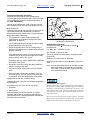
Operating Instructions
70°
45°
Normal gauge readings are in the 0.8 inch to 4.0 inch
water pressure range, and vary considerably with crop.
90
60
2
Refer to Figure 25
Use tractor remote hydraulic valve flow control to set fan
speed and butterfly valve adjustment to make fine
adjustments to meter pressurization. Precise technique
depends on tractor capabilities:
• Preset the butterfly valve. Use any setting that you
previously developed for the crop/disk/range (see Note
at right), otherwise:
20°
30
0
1
848-020C
• The objective is to obtain recommended meter
pressurization, and maintain it during end-of-pass
marker fold, lift and turn.
• For any setup adjustment, operate the tractor engine
at typical field rpms, and not at idle.
31
Figure 25
Fan Butterfly Valve Handle
Butterfly Valve Operation:
To adjust, loosen bolt 1 and rotate the handle
Re-tighten bolt.
25137
2.
0° is wide open - maximum air flow.
90° is closed - minimum air flow.
If the tractor has fine control of remote flow rates, and
consistent flow at varying tractor engine rpm, initially
set the butterfly valve to 30° or less.
The valve provides the most effect at settings between
20° and 70°.
Starting at 30° reduces the fan workload.
If the tractor has only coarse control of flow, initially set
the butterfly valve to 45°.
• Set the fan circuit flow to bring the gauge reading to
near the recommended value.
• Fine tune the meter pressurization with the butterfly
valve.
Starting at 45° provides the most adjustment range up or
down.
Note: You may find that different crop, seed disk and rate
range combinations need different valve settings.
If so, make a note of the valve angle on the chart
in the Seed Rate manual.
• If the tractor has marginal flow available, or the list
circuit has priority, you may need to experiment with
combinations of fan flow and butterfly valve settings.
Always start the fan with a low flow setting.
Gradually bring fan up to the recommended initial meter
pressurization.
At excessive rpm, too much air flow can cause:
• oil heating
• slow lift times
If desired pressure cannot be reached, or requires
unusually high oil flow at low butterfly valve settings,
chances are the fan is running backwards. Reverse the
inlet/return lines at the hitch.
2015-01-26
Low Population Risk at Turns:
The fan requires up to 4.5 gpm. This figure does not include oil
for lift/lower or oil for marker operation. Aggressive lift/lower
operations, and simultaneous lift/marker operations, can
reduce fan rpm below that needed to pressurize meter disks. If
seed falls out of pockets, low population bands will occur
shortly after turns.
Unless the tractor has generous oil flow capacity, raise/fold
markers before lift, and lift slowly. Watch meter pressurization
and tune operations to keep it at planting levels in turns.
Table of Contents
Index
401-652M
32
YP4-6-825A3P
Table of Contents
Index
Great Plains Manufacturing, Inc.
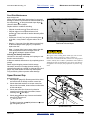
Air-Pro® Meter Operation
1
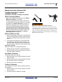
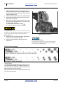
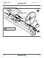
Refer to Figure 26
The meter disk is driven, top forward, by a chain drive
(not shown) always connected to the section drive shaft.
At non-planting rows, use a blank disk (page 59).
5
Seed is air-delivered to the inlet above the air release
screen 1 . Seed customarily fills to the top of the screen,
blocking further air flow from the seed delivery system,
until the seed level falls below the screen.
7
2
Seed enters the meter at the seed inlet shutter 2 (if
open), and forms a seed pool 3 at the base of the meter.
Seed pool size is controlled by the shutter handle 4
setting (which is the only user adjustment at the meter).
Initial shutter settings are given in the seed rate charts.
Meter pressurization air enters the meter at 5 , and exits
the meter primarily at the seed pockets in the seed disk.
The pressure differential holds seed in the disk
pockets 6 rising from the seed pool. Excess seed at a
pocket is picked off by the tickler brushes 7 .
6
8
4
3
The strip and drop brushes block meter pressurization
air. Seeds passing the drop brush 8 are free to fall into
the seed tube, and are detected by the seed sensor 9 .
Meter Operation
1. Install disks for your crop/population range per the
Seed and Fertilizer Rate manual and the instructions
beginning on page 57 of this manual.
9
2. Open the shutter at planting rows to the
recommended initial setting (from the Seed Rate
charts). At unused rows, install a blank disk
(page 59) and close shutter.
3. Set sprocket indexing if staggering a twin-row crop
(see Seed and Fertilizer Rate manual for details).
4. Operate fan to achieve suggested manifold pressure
(Seed and Fertilizer Rate manual, and page 43).
5. Open slide gates to fill meters (page 24).
Figure 26
Air-Pro® Seed Meter at Row
6. With all rows primed, rotate meters one turn to fill
pockets to edge of drop brush. Rotate the drive shaft
(top forward) with a 7⁄8 inch (23 mm) wrench, or raise
and rotate ground drive wheel (top forward).
29825
7. Leave fan running (to keep seed in top pockets).
Re-install rain covers. Commence planting.
Meter operation is automatic from this point on.
See also:
“Seed Pool Troubleshooting” on page 65,
“Meter Clean-Out” on page 76, and
“Meter Brush Maintenance” on page 77.
401-652M
Table of Contents
Index
2015-01-26
Great Plains Manufacturing, Inc.
Table of Contents
Index
Operating Instructions
33
Marker Operation (Option) S/NTHIS PAGE APPLIES ONLY TO MODELS:
(YP3P425A s/n B1004M-)
(YP3P625A s/n B1006P-) (YP3P825A s/n B1007R-)
Before Operating Markers
• Make sure cylinders are properly bled. See “Marker
Maintenance (Option)” on page 82.
• This section presumes correct marker extension for
your pass spacing. If this has not been set, or needs to
be changed, see “Marker Extension” on page 115.
• Markers are equipped with an automatic sequence
valve that controls which side activates, as well as
marker deployment speed. Marker folding speed is
adjusted via set screws on the sequence valve body.
Excessive folding speed may damage markers. Set
speed prior to first field operations. See “Marker
Speed Adjustment” on page 114.
Overhead, Crushing and Sharp Object Hazards:
Do not allow anyone to stand near or beyond the end of the
wings during marker operations. There is risk of serious injury
or death for anyone in the path of a marker. Marker arms are
heavy, are under tremendous hydraulic power, and may move
suddenly if the hydraulic system is damaged or needs bleeding.
Marker discs may be sharp.
Marker Unfold (one side)
1. Move tractor hydraulic control (lever or switch) for the
marker circuit (typically to Extend). Hold until marker
is completely unfolded. Do not leave tractor control in
detent.
2. If the marker side operating is not the desired side,
let it unfold part way, and move the tractor’s circuit
control to Retract. When the marker is folded, move
the circuit control to Extend to activate the other side.
Both Sides Unfolded
With both markers in the upright/tilted positions:
1. Unfold either side, and when completely deployed:
2. Move lever/switch to Retract momentarily, and return
to Extend to deploy other side.
Row Marker Operation
To alternate which side is marked:
1. Move the tractor’s circuit control to Retract. Hold until
marker is folded.
2. Move the tractor’s circuit control to Extend. Hold until
the new side’s marker is fully unfolded.
3. Return tractor control to neutral/off.
Folding The Markers
If your planter has markers, fold them before performing
a lift operation.
1. Move the tractor’s circuit control to Retract. Hold until
marker is folded.
2. Tilt markers down for transport or storage.
2015-01-26
Table of Contents
Index
401-652M
34
YP4-6-825A3P
Table of Contents
Index
Great Plains Manufacturing, Inc.
Marker Operation (Option) S/N+
THIS PAGE APPLIES ONLY TO MODELS:
(YP3P425A s/n B1005M+)
(YP3P625A s/n B1007P+) (YP3P825A s/n B1008R+)
Before Operating Markers
• Make sure cylinders are properly bled. See “Marker
Maintenance (Option)” on page 82.
• This section presumes correct marker extension for
your pass spacing. If this has not been set, or needs to
be changed, see “Marker Extension” on page 115.
• Markers are equipped with an automatic sequence
valve that controls which side activates, as well as
marker deployment speed. Marker folding speed is
adjusted via set screws on the sequence valve body.
Excessive folding speed may damage markers. Set
speed prior to first field operations. See “Marker
Speed Adjustment” on page 114.
Overhead, Crushing and Sharp Object Hazards:
Do not allow anyone to stand near or beyond the end of the
wings during marker operations. There is risk of serious injury
or death for anyone in the path of a marker. Marker arms are
heavy, are under tremendous hydraulic power, and may move
suddenly if the hydraulic system is damaged or needs bleeding.
Marker discs may be sharp.
Marker Unfold (one side)
1. Move tractor hydraulic control (lever or switch) for the
marker circuit (typically to Extend). Hold until marker
is completely unfolded. Do not leave tractor control in
detent.
2. If the marker side operating is not the desired side,
let it unfold part way, and move the tractor’s circuit
control to Retract. When the marker is folded, move
the circuit control to Extend to activate the other side.
Row Marker Operation
To alternate which side is marked:
1. Move the tractor’s circuit control to Retract. Hold until
marker is folded.
2. Move the tractor’s circuit control to Extend. Hold until
the new side’s marker is fully unfolded.
3. Return tractor control to neutral/off.
Marker Controls
The marker controls are in circuit with the lift controls.
The markers raise and lower with the planter.
When the planter is lowered:
• One side marker will unfold.
• Hold the hydraulic control until marker is fully
extended.
When the planter is raised:
• The marker will fold up.
• Hold the hydraulic control until the marker is fully
folded.
The next time the planter is lowered the opposite side
marker will unfold.
401-652M
Table of Contents
Index
2015-01-26
Great Plains Manufacturing, Inc.
Table of Contents
Index
Operating Instructions
35
Field Set-Up Checklists
Use the following tables to develop a final checklist for
your tractor/planter configuration.
Mechanical Checklist (Hitching)
Page
Planter hitched
Parking stands raised
Additional or fewer steps may be necessary depending
on tractor features, planter options and planting
accessories.
Air System Checklist
13
17
Electrical Checklist
Fan butterfly valve set
Seed loaded. Lids closed.
Meter shutters open to chart value
No air leaks (except from seed hoppers)
Hoses and tubing - no sags, no pinches
Check both manifold and sensor lines
Hoses fully connected to meters
Page
Verify electrical hookups solid
Check seed monitor terminal and observe
any diagnostic messages
Option: Verify that, when planter is
lowered, optional radar speed sensor is
pointed at ground, at an angle
approximately 35° below horizontal.
13
a
b
Row Units Checklist
Preset depth handles alike.
Preset down force springs alike, except in
tracks.
Option: Set all unit-mounted coulters to
1⁄ inch shallower than opener blades.
4
Check coulter alignment to row
Check closing wheel alignment
Set press wheels alike, except in tracks.
Check action and contact of side depth
wheels
Check wheel scraper gaps (if installed)
Slide gates open
a. Refer to monitor manual.
b. Refer to sensor documentation.
Hydraulic System Checklist
Page
Check tractor hydraulic reservoir full
Fan case drain
Fan return
Fan motor pressure side (retract)
Inspect connections for leaks
Check fan speed and airflow direction
16
a
a. Operate fan briefly. Observe rotor blades spinning
toward exit port as fan slows to a stop.
Meters Checklist
Mechanical Checklist (post-Hitching)
Page
Planter leveled
Marker extension set
Marker disc angle set
Markers folded (unless already at start of
first planting row)
Planter Meter Drive Checklist
18
115
42
33
Page
Check chain lubrication and slack
Calibrate speed sensor pulses with planter
lowered.
Seeding: Set/check Range and
Transmission against rate chart
83
Corn?
Check timing of meters for twin-row
Check chain tension. Re-connect any
loose idler tensioning springs.
Correct disks for seed
Start fan. Operate at field manifold
pressure.
Rotate meter drive shafts one turn disks
with seed.
Page
31
24
55
Page
52
47
50
51
62
62
53
54
24
Page
a
a
29
32
a. Refer to Seed and Fertilizer Rate manual.
a
b
a. Refer to seed monitor manual.
b. Refer to Seed and Fertilizer Rate manual.
2015-01-26
Table of Contents
Index
401-652M
36
YP4-6-825A3P
Table of Contents
Index
Great Plains Manufacturing, Inc.
Field Operation
Perform all steps in “Pre-Start Checklist” on page 20
and “Field Set-Up Checklists” on page 35.
First Pass Operation Checklist
1.
2.
3.
4.
5.
6.
7.
8.
Slide gates open. Shutters set.
Raise planter and line up at start of first
planting row.
Prime meters with seed.
Leave fan running.
Unfold marker on next-row side.
Pull forward, lower planter, and begin
planting for a short distance.
Stop. Assess:
• planting depth
• seed spacing
• press wheel operation
Make necessary adjustments
Resume planting.
Sharp Field Turnsa Checklist
1.
2.
3.
4.
5.
6.
Page
32
20
32
33
20
-
Suspending Planting Checklist
1.
2.
3.
4.
5.
Stop tractor
Fan hydraulic circuit to Float or Neutral
Hydraulic drive circuit to Float or Neutral
Fold Marker
Raise planter
Ending Planting Checklist
1.
2.
3.
Suspend operations as above, then
Lights ON
Transport
Page
29
33
20
Page
21
38
-
Page
Fold marker
Raise planter when fold is complete
Make turn
Lower planter
Unfold marker on next-row side.
Resume planting.
33
20
20
33
a. Monitor manifold pressure during end-of-pass
operations and turns. Adjust operations as needed
to maintain meter pressurization.
Consult seed monitor for alarms during planting. Check
that reported rates are consistent with your plan.
When reloading seed, check consumption against
anticipated use to that point.
401-652M
Table of Contents
Index
2015-01-26
Great Plains Manufacturing, Inc.
Table of Contents
Index
Operating Instructions
37
Short-Term Parking
Long-Term Storage
1. Fold markers (page 33).
1. Complete Parking steps (page 37). Park the planter
indoors if possible.
2. Choose a location with level firm ground. Do not
unhitch on a steep slope.
3. Raise planter to just off ground.
4. Lower parking stands to ground and pin (page 17).
5. Lower planter.
6. Set hydraulic circuits to neutral.
7. Disconnect hydraulic lines. Secure them so that they
do not touch the ground.
8. Disconnect electrical cables, capping where
provisioned.
9. Unhitch.
Restart tractor and pull away from planter.
2. See “Material Clean-Out” on page 75. Clear all
seed from seed container, air box, seed delivery
system and meters.
3. Close slide gates and latch hopper lids.
4. Remove seed disks from meters (this is primarily to
relieve pressure on brushes). Clean disks of residue
build-up (see Caution at right). Use mild soap,
non-abrasive scrubbers, and hot or warm water. If
using sealed storage, dry disks prior to storage.
Possible Chemical Hazard:
Seed disks will have talc and graphite residue, and may have
residues of hazardous seed treatments. Do not wash disks
where food is prepared, or where cookware or dinnerware is
washed. Wear gloves when washing disks. Avoid spray.
Although the disks are dishwasher-safe, do not wash them in
an appliance also used for food cookware or dinnerware.
5. Tie or tape a small plastic bag over ends of all seed
delivery tubes to prevent insects from entering or
nesting.
6. Close seed inlet shutters at meters (to prevent pest
entry to seed hoses). Thoroughly clean seed and
seed treatment residue from seed meters. See
“Meter Clean-Out” on page 76, for more information.
7. Clean planter of mud, dirt, excess oil and grease.
8. Lubricate all points listed in Maintenance.
9. Apply grease to exposed cylinder rods to prevent
rust.
10. Inspect planter for worn or damaged parts. Make
repairs and service during off season.
11. Use spray paint to cover scratches, chips, and worn
areas on the planter to protect the metal.
12. Cover planter with a tarp if stored outside.
2015-01-26
Table of Contents
Index
401-652M
38
YP4-6-825A3P
Table of Contents
Index
Great Plains Manufacturing, Inc.
Adjustments
To get full performance from your YP425A3P, YP625A3P
& YP825A3P planter, you need an understanding of all
component operations, and many provide adjustments
for optimal field results. Some of these have been
covered earlier in this manual.
Adjustment
Even if your planting conditions rarely change, some of
these items need periodic adjustment due to normal
wear.
Page
The Adjustment Affects
Frame height
21
Planting depth consistency
Frame level
18
Planting consistency
Air System
27
Fan Speed
a)
Meter Pressurization (values from SRM
Planting Rate
31
Optimal seed distribution
43
Consistent seed flow and disk singulation
SRMa
Refer to Seed and Fertilizer Rate manual
Marker Adjustments
Marker Extension
115
Intended swath spacing
Marker Speed Adjustment
114
Reliable marker operation
Opener Depth
52
Planting depth
Row Unit Down Pressure
47
Planting depth uniformity
Row Unit Lock-Up
60
Single/twin-row operation
Row Cleaner Adjustments (Option)
49
Row preparation
Coulter Adjustments (Option)
50
Seed depth uniformity
Opener Disk Adjustments
52
Seed depth, seed-to-soil contact
Side Depth Wheels
52
Seed depth, prevents plugging
Adjusting Gauge Wheel Scrapers
54
Consistent seed furrow depth
Seed Meter Setup and Adjustment
55
Consistent seed population
Seed Firmer Adjustments (Option)
61
Seed-soil contact
Press Wheel Adjustment
62
Effective soil coverage
25AP Row Unit Adjustments
PMb
Monitor Adjustments
Refer to Seed Monitor manual
a. SRM: Seed and Fertilizer Rate manual (401-651B)
b. PM: DICKEY-john® Planter Monitor operator manuals
401-652M
Table of Contents
Index
2015-01-26
Great Plains Manufacturing, Inc.
Table of Contents
Index
Adjustments
39
Setting Material Rates
Full details on rate setting sprocket selection and
installation are found in the Seed Rate Manual (pub.
number 401-651B). This is a summary. Setting the
seeding rate requires the following steps:
1. monitor setup
2. seed disk selection,
3. drive speed Range sprockets,
4. Transmission sprockets,
5. inlet shutters
6. meter pressurization,
7. checking seeding rate.
All rate adjustments are performed at the left end of the
planter. There are no adjustments at the ground drive
assembly.
Planting Rate Details
1. Rate: Monitor configuration:
The seed monitor must be set up with the
• correct row count,
• correct row spacing,
• speed calibration and;
• expected population limits, in order to have accurately
rate reports and useful alarms.
See the Seed and Fertilizer Rate manual (401-651B) and
the DICKEY-john® Planter Monitor operator (PM)
manual.
If you only plant with the factory configuration of the
planter, you never need to update row count and
spacing. If any rows are unused, adjust the monitor
setup.
Figure 27
Monitor Setup Screen
29978
Figure 28
Air-Pro® Seed Disks
29594
Speed calibration must be done prior to first use, and
re-calibration is recommended periodically, particularly if
soil conditions change.
2. Rate: Disk Selection:
The Seed and Fertilizer Rate manual (401-651B) has a
table of recommended disks. Disks are specific to crops.
Some crops have multiple disks available, to cover both
seed varieties, and different populations within disk rpm
limits. Disks have a high and low rpm limit, which also
corresponds to a high and low field speed limit. The
charts account for these limits.
See “Air-Pro® Meter Disk Installation” on page 57.
If any rows are unused, install special blank disks. See
“Row Unit Shut-Off” on page 58.
2015-01-26
Table of Contents
Index
401-652M
40
YP4-6-825A3P
Table of Contents
Index
Great Plains Manufacturing, Inc.
3. Rate: Range Sprockets
Range sprockets provide coarse control of seed rate.
Refer to Figure 29 and Figure 30
All Seed Rate charts specify a DRIVING and DRIVEN
sprocket combination for the Range. Crops with more
than one range are noted as “LOW RANGE” or “HIGH
RANGE” at the top of the chart.
3
DRIVING
To change Range:
a. Loosen the bolt securing the idler plate
Disengage the idler.
Remove the chain.
b.
c.
3.
Remove pins from shaft ends at DRIVING and
DRIVEN sprockets, as well as at storage shaft
left end of frame.
DRIVEN
1
at
Exchange sprockets so that new DRIVING and
DRIVEN sprocket tooth counts (stamped on sprocket
face) match chart. Re-pin all shafts.
Figure 29
Range Sprockets
d. Remount chain (see page 83). Re-engage idlers for
1⁄ inch (6.4 mm) slack in longest chain span.
4
4. Rate: Transmission Sprockets
Transmission sprockets provide fine control of seed rate.
Each chart row provides a rate adjustment of 2 to 3%.
1
Refer to Figure 30
Each Seed Rate chart row has a unique pairing of
DRIVING and DRIVEN Transmission sprocket.
DRIVING
4
To change Transmission:
a. Loosen the bolt securing the idler plate
Disengage the idler.
Remove the chain.
b.
c.
31030
4.
Remove pins from shaft ends at DRIVING and
DRIVEN sprockets, as well as at storage shaft
left end of frame.
1
at
DRIVEN
Exchange sprockets so that new DRIVING and
DRIVEN sprocket tooth counts (stamped on sprocket
face) match chart. Re-pin all shafts.
Figure 30
Transmission Sprockets
31030
d. Remount chain (see page 83). Re-engage idlers for
1⁄ inch (6.4 mm) slack in longest chain span.
4
401-652M
Table of Contents
Index
2015-01-26
Great Plains Manufacturing, Inc.
Table of Contents
Index
Adjustments
5. Rate: Seed Inlet Shutter
A consistent seed results from having a consistent
number of seeds (usually one) in each pocket of the
seed disk, avoiding “skips” (fewer seeds per pocket) and
“doubles” (excess seed per pocket).
41
5
Refer to Figure 31
One of the factors that affects seed pickup at the disk is
having an optimal seed pool (page 56). The depth of the
seed pool is controlled by the seed inlet shutter 5 .
Each Seed Rate chart specifies a suggested initial
shutter setting. See “Seed Inlet Shutter Adjustment” on
page 55 for setting details, and further adjustment.
At unused rows, set the shutter to zero/closed to prevent
loss of meter pressurization air. Install a blank disk. See
“Row Unit Shut-Off” on page 58.
Figure 31
Seed Inlet Shutter: Setting III
29607
Figure 32
Meter Pressure Gauge
29842
6. Rate: Meter Pressurization
Refer to Figure 32
(which depicts a typical reading for some densities of corn)
A major factor that affects seed pickup at the disk is
optimal meter pressurization. Fan air holds the seed in
the disk pockets until they pass the drop brush
(page 32).
The Seed and Fertilizer Rate manual has a section with
suggested initial meter pressures, which may be a single
value, or a graph based on seed density.
Meter pressure is set by a combination of tractor circuit
lever and fan butterfly valve (page 31). See “Air System
Operation” on page 27.
7. Rate: Checking
Although the seed monitor reports a computed
population based on seeds sensed, only an actual furrow
check provides certainty about the actual seeding rate.
See the Seed and Fertilizer Rate manual.
2015-01-26
Table of Contents
Index
401-652M
42
YP4-6-825A3P
Table of Contents
Index
Great Plains Manufacturing, Inc.
Marker Adjustments (Option)
See also:
• “Initial Marker Setup (Option)” on page 114 for
marker speed and marker extension
• “Marker Operation (Option) S/N-” on page 33; and,
• “Marker Maintenance (Option)” on page 82 for
marker shear bolt and marker hydraulic bleeding
Marker Disk Adjustment
Sharp Object Hazard:
Use caution when making adjustments in this area.
Marker disks may be sharp.
Sharp Overhead Object and Pinch/Crush Hazards:
Never allow anyone near the planter when folding or
unfolding the markers. Markers may fall quickly and
unexpectedly if the hydraulics fail. Anyone beneath may be
injured if hit by an unfolding marker, or caught in a folding
marker.
Refer to Figure 33
1. To change angle of cut, and the width of the mark,
loosen 1⁄2 inch bolts 2 holding the disk assembly.
1
W
T
T
N
For a wider mark W, increase the angle of the
marker with respect to the tube 1 . For a narrower
mark N , reduce the angle.
Note: Do not set a marker angle wider than needed to
make a useful mark. Excess angle increases wear
on all marker components.
2. Tighten bolts
2
2
.
Note: Direction of travel T tends to drive the disk angle to
Wide. If bolts are not tight enough, or loosen over
time, disk slips into the Wide mark configuration.
Figure 33
Marker Disk Angle
11757
Figure 34
Marker Disk Angle (S/N+)
31974
Refer to Figure 34
Applies to planters with serial numbers:
(YP3P425A s/n B1005M+)
(YP3P625A s/n B1007P+) (YP3P825A s/n B1008R+)
Current markers are equipped with an additional marker
disk adjust mount 3 which gives the marker added
capability of up/down direction of movement where
previously it only performed side to side movement.
Additionally, the markers are able to make a wider mark
in the field.
3
401-652M
Table of Contents
Index
2015-01-26
Great Plains Manufacturing, Inc.
Table of Contents
Index
Adjustments
43
Fan and Adjustment
1. These steps presume that correct seed disks are
installed (per Seed Rate Manual), and the seed inlet
shutters are set for the seed (page 55).
2
2. With fan off, check meter pressurization reported by
the Magnehelic®a gauge. Re-zero as needed.
3
3. Determine the recommended meter pressurization
based on your own notes or the published value in
the Seed Rate Manual.
4. Put tractor in Park and set brakes. Set tractor engine
speed to typical field rpm. Lift planter.
5. Start the fan. Gradually increase fan speed using the
tractor’s hydraulic flow control for the circuit. Using
hydraulic flow and/or the butterfly valve, adjust meter
pressurization to the developed or suggested value
from step 3.
6. Rotate ground drive wheel to fill meters. Meters are
filled when seed begins emerging below two or more
openers. With fan running, put the tractor in Park and
set the brakes. Walk behind the wings, remove
several rain covers, and check for seed in meters by
looking through the clear disks.
7. Re-check meter pressurization. With meters and
disks filled, air loss through empty disk pockets is
reduced, and meter pressurization can change.
4
1
Figure 35
Magnehelic® Gauge
29842
Re-zero the Magnehelic® gauge on level ground with
the fan off, and if possible, under no-wind conditions.
Turn the set screw 1 on the meter face until it reads
zero from the tractor driver’s viewing position.
Port ID for Troubleshooting:
2 Over-pressure relief port (with plug in place)
3 Low-pressure port (breather/atmospheric pressure)
4 High-pressure port (from manifold chamber)
8. Begin planting. Troubleshoot any obvious problems
or optional seed monitor alarms.
9. During the first pass, take note of the average
populations reported on the optional seed monitor.
If the reported seed monitor population varies from
your intentions by a significant amount, it is
imperative to perform a furrow check.
For serious rate variances, for which the source of
the problem and the solution are not quickly
determined, see “Population Troubleshooting
Charts” on page 67.
If the population is only slightly low, the problem can
be skips (periodic empty disk pockets). If slightly
high, the problem can be doubles (period pockets
with double seed). An adjustment to the meter
pressurization may correct either condition (see
step 12).
Small seeds, such as Milo, may be under-reported by
the seed monitor. Use the “Alternate Skip/Double
Check” below to verify seed status at the disc pockets.
Furrow Check:
Expose several seeds in each of several rows, being
careful not to disturb their relative positions. Measure
and average the distance between seeds. Compare this
to the predicted seed spacing for the population in the
Seed Rate Manual.
Any instances of no seed where expected may be a
sign of “skips”. Finding two seeds at the same spot is
clear indication of “doubles”
a. Magnehelic® is a registered trademark of Dwyer Instruments, Inc.
2015-01-26
Table of Contents
Index
401-652M
44
YP4-6-825A3P
Table of Contents
Index
Great Plains Manufacturing, Inc.
10. Resume planting.
A small varying population deviation between rows is
normal. If a row is consistently running lower or
higher than the other rows, it could indicate a meter
or seed sensor problem that needs attention.
“Population Troubleshooting Charts” on page 67.
11. Continue to monitor meter pressurization.
When oil reaches operating temperature, fan speed
can change. Expect to make periodic adjustments to
fan circuit or butterfly valve to maintain ideal meter
pressurization.
12. Skips:
If all else is correct, and the overall average
population is running low (or there are gaps upon
furrow check), the cause may be seeds falling out of
disk pockets before delivery to the seed tube.
Increase meter pressurization to correct this.
Insufficient meter pressurization, or unusually rough
fields, can increase the incidence of empty pockets. Be
sure to rule out other causes (such as skipping chains,
meter starvation, incorrect meter disks) before adjusting
meter pressurization to reduce apparent skips.
13. Doubles:
If all else is correct, and the overall average
population is running high (or there are double seeds
upon furrow check), the cause may be two seeds in
some disk pockets at delivery to the seed tube.
Decrease meter pressurization to correct this.
Excess meter pressurization can increase the incidence
of doubles. Be sure to rule out other causes (such as
incorrect meter disks) before adjusting meter
pressurization to reduce doubles.
Fine-Tuning Meter Pressurization
After several passes, and you are comfortable with the
planter’s operation, you can optimize meter
pressurization. Use this method during longer passes, so
there are fewer distractions (and see sidebar regarding
Milo).
Alternate Skip/Double Check
Small seeds, particularly Milo, are less reliably sensed as
skips or doubles by the seed tube sensors, and watching
monitor population is unlikely to locate the pressure
limits. This test can also be quicker for all seeds.
14. Observe the current overall average population
reported by the monitor.
A. After planting a few passes with initial settings,
remove the rain covers from several rows (use rows
with a variety of seed hose lengths and routes).
15. Adjust the fan speed down, in small steps, waiting
5-10 seconds between adjustments, until skips occur
(actual population begins falling below target). Note
the pressure at which skips begin.
16. Restore pressure to the initial value at step 14.
17. Adjust the fan speed up, by periodic small
increments, until doubles occur (actual population
begins rising above target). Note the pressure at
which doubles begin.
18. Adjust meter pressurization to a value halfway
between the limits established at step 15 and
step 17. This is the ideal value for your crop, disk and
population, providing equal margin against skips and
doubles. Record this value for future use.
401-652M
B. Make a meter pressurization adjustment. Resume
planting for a pass or less.
C. Stop planter motion but leave engine at field rpm and
fan running.
D. Inspect the seed disks closely. Look for empty seed
cells (skips) and cells with multiple seeds (doubles).
E. Repeat step B-to-step D until limits are established.
Record limits. Re-install rain covers. Plant with
median settings.
Table of Contents
Index
2015-01-26
Table of Contents
Great Plains Manufacturing, Inc.
Index
Adjustments
45
Gauge Wheel Adjustments
The minimum tool bar height is limited by the gauge
wheels. In some conditions, such as ridge planting, you
may need to use a tool bar height lower than 26 inch.
Refer to Figure 36
There are two adjustments for this at the gauge wheels.
1
• Gauge wheel yoke spring length 1 :
This provides a variable height reduction of up to
2.2 inch (5.6 cm).
• Axle hole change 2 :
This provides a 2 inch (5.1 cm) height reduction.
Making both adjustments provides up to 4.2 inch
(10.7 cm) of tool bar height reduction.
Yoke Spring Adjustment
Refer to Figure 37
Check the length
3
2
of all springs before adjusting.
The maximum (and factory set) spring length is:
3 3.0 inch (7.6 cm)
The minimum spring length is:
3
3 2 ⁄8 inch (6.0 cm)
Figure 36
Gauge Wheel Height
Each 1⁄8 inch of spring compression raises the wheel by
approximately 0.44 inch (3.5 mm per mm).
31054
To adjust the spring length:
1. Raise the planter until the gauge wheels are slightly
off the ground. Place blocks or jack stands under the
frame for safety.
4
Note: If there is weight on the wheels, the springs may
have additional compression and may not be at a
length you can usefully measure.
2. Loosen the jam nut
4.
3. Rotate the adjuster nut
length.
5
to set the new spring
3
4. Tighten the jam nut.
5
Wheel Axle Adjustment
If the target tool bar height cannot be achieved with the
spring adjustment, relocate the wheel axles in the arms.
This lowers the planter by about 2 inch (5.1 cm).
1. Raise the planter until the gauge wheels are slightly
off the ground. Place blocks or jack stands under the
frame for safety.
2. Remove bolts 2 , located in lower holes, securing
transport ground tire assembly to unit.
Figure 37
Gauge Wheel Spring Length
3. Move wheel assembly and secure assembly to upper
hole using previously removed bolt.
2015-01-26
Table of Contents
Index
31053
401-652M
46
YP4-6-825A3P
Table of Contents
Index
25AP Series Row Unit Adjustments
Refer to Figure 38 (which depicts a row unit populated with
most optional accessories supported for use with the
YP425A3P/625A3P/825A3P Air Planter)
From front to back, a Great Plains 25 Series Air-Pro® row
unit can include the following capabilities (some
optional):
Great Plains Manufacturing, Inc.
3
2
4
8
5
1
6
7
9
1. Lock-Up Pin Storage Hole (Hole Standard)
See “Row Unit Shut-Off” on page 58.
2. Down-Pressure Cam (Standard)
Row units are mounted on parallel arms. This
parallel-action mounting allows the row-unit to move
up and down while staying horizontal. Springs add
an adjustable force, set by the cam, to the row
weight. See “Row Unit Down Pressure” on
page 47.
14
10
3. Meter Pressurization Air Inlet (Standard)
Pressure-regulated air enters the meter here and
holds seed in the disk pockets. See “Fan and
Adjustment” on page 43.
11 12
13
15
Figure 38
25AP Series Row Unit
16
29983
4. Seed Delivery Hose Inlet (Standard)
When the hopper slide gate (not shown) is open,
gravity carries the seed into the meter at the
shutter 6 . The hose is easily removed for inspection.
There are no adjustments.
11. Unit-Mount Coulter (Option)
Coulters cut remaining trash and begin opening the
seed furrow. Working depth is set by row depth and a
mounting hole selection. See “UMC Coulter
Adjustments” on page 50.
5. Air-Pro® Seed Meter (Standard, Choice of Disks)
See “Air-Pro® Meter Disk Installation” on page 57.
12. Opener Discs (Standard)
Row-unit double disc openers create the seedbed
furrow. They have adjustments for angle and
spacing. See “Row-Unit Opener Disk
Adjustments” on page 52.
6. Seed Inlet Shutter (Standard)
This controls the level of bulk seed at the disk. There
are four operating settings, plus fully open
(clean-out) and fully closed (shut-off or storage). See
“Seed Inlet Shutter Adjustment” on page 55.
7. Side Gauge Wheel Depth (Standard)
The T-handle sets planting depth by controlling the
height of the side gauge wheels relative to the
opener discs. See “Side Gauge Wheel
Adjustment” on page 53.
8. Press Wheel Force, Angle, Stagger (Standard)
The press wheels close the furrow, gently pressing
the soil over the seed to ensure good seed to soil
contact for even emergence. See “Press Wheel
Adjustment” on page 62.
9. Row Unit Lock-Up Hole (Hole Standard)
Pins are standard on some models. With the row unit
raised above level, the lock-up pin is inserted here.
See “Row Unit Shut-Off” on page 58.
10. Row Cleaner (Option)
Row cleaners clear trash from the row, to a depth set
by an adjustment on the arms. See “Unit-Mount
Cleaner Adjustments” on page 49.
401-652M
13. Seed Tube with Sensor (Standard)
Requires no adjustment.
14. Scrapers (Optional, not shown)
Inside scrapers require no adjustment. For gauge
wheel scrapers, see “Adjusting Gauge Wheel
Scrapers” on page 54.
15. Seed Firmers (Seed Flap Standard, not shown)
An optional seed firmer (Keeton shown) minimizes
seed bounce and improves soil contact. It may also
deliver fertilizer. See “Seed Firmer Adjustments”
on page 61.
16. Press Wheel Type (Choice)
A variety of single and dual press wheel assemblies
are available, some region-specific. Consult your
Great Plains dealer.
Equipment Damage Risk:
Do not back up with row units in the ground. To do so will
cause row unit plugging and may result in severe damage.
Table of Contents
Index
2015-01-26
Great Plains Manufacturing, Inc.
Table of Contents
Index
Adjustments
47
Row Unit Down Pressure
Refer to Figure 39
The ideal amount of down-force causes the side gauge
wheels to compress any loose surface soil, but not press
a trench into subsoil.
{
To assess down-force, operate the planter for a short
distance on typical ground (with or without seeding), and
stop. Leave the planter lowered (row units in ground).
At several row units, inspect the furrow created by the
opener discs, but prior to furrow closing by the press
wheels.
Inspect Furrow Here
Figure 39
Checking Furrow
Note: Be sure to inspect rows both in and out of tire
tracks.
Refer to Figure 40
1. If the side gauge wheels are leaving no tracks, or
light tracks, increase down-force.
2. If the wheels are compressing trash and loose soil,
and leaving clear tracks right at the top of the
subsoil, down-force is probably correct and needs no
adjustment.
3. If the wheels are creating a trench into the subsoil,
down-force is too high and needs to be reduced.
29983
1
Insufficient down-force
Increase down-force
Gauge wheels compress
loose soil only
Ideal
No adjustment required
Side gauge wheels
making deep tracks
Down-force too high
Reduce down-force
Light or no side gauge
wheel tracks
2
3
Figure 40
Assessing Down-force
Adjusting Down-Force
Refer to Figure 41
Row unit springs 1 provide the primary down pressure
necessary for row unit disks to open a seed trench. The
weight of the row units themselves contributes about
130 pounds (59 kg) of the total force.
The springs allow the row units to float down into
depressions and up over obstructions. Springs also
provide down force on coulters when using optional row
mounted coulters, and provide the primary down force on
row cleaners (optional), seed firmers (optional) and
press wheels.
1
Figure 41
25AP Series Row Unit Springs
2015-01-26
Table of Contents
Index
29983
401-652M
48
YP4-6-825A3P
Table of Contents
Index
Great Plains Manufacturing, Inc.
An adjuster cam 2 sets down pressure individually for
each row unit. This is useful for penetrating hard soil and
planting in tire tracks. For best results always adjust
tractor tires so they are not ahead of 30 inch rows.
Refer to Figure 43
3
Cam Notch
Pounds
zero (out of notch)
Kilograms
Lock-Up & Maintenance
one
305
140
two
330
150
three
365
165
four
425
195
five
485
220
six
tip
545
250
Do Not Use
Values are down force with hoppers empty
2
5
Figure 42
25AP Series Row Unit
Spring Adjustment
29958
Use only enough down pressure to cut the seed trench
and maintain proper soil-firming over seed. With a full
seed load, the force on each row is up to 120 pounds
higher at start of planting.
31034
4
Excessive row unit spring force will lead to premature
wear on row unit components and uneven seed depth. If
all rows are set to cam 4, some lighter planter
configurations could be lifted out of ground contact.
6
Refer to Figure 42 (shown at cam setting 2),
Figure 43 and Figure 44
To adjust down pressure, use a 11⁄8 inch (29 mm) open
end wrench or the tool 3 stored at the left end of the
planter.
Figure 43
Row Unit Minimum Cam (at 1)
27065
bottom
1. Raise the planter. Although this adjustment can be
made with the planter lowered, the springs will be in
tension, and will require more effort. The extra force required may also damage tools.
2. Install lift cylinder locks.
3. Put tractor in Park and shut it off.
4. Position wrench on the fixed nut
forward of vertical.
5. Pull upper spring link
5
4
near or slightly
back.
6. Move the adjustment cam
the spring adjust bar 6 .
2
to the new setting on
Note: Do not set all rows higher than notch four. Using
high settings across all rows causes uneven
planting. Individual rows may be set higher if
running in tire tracks. On twin-row configurations,
setting all rows to notch 4 or higher results in a net
up force that can exceed the weight of the planter
when the hoppers are nearing empty.
401-652M
Table of Contents
Figure 44
Row Unit Maximum Cam (at 6)
Index
27065
top
2015-01-26
Great Plains Manufacturing, Inc.
Table of Contents
Index
Adjustments
49
Unit-Mount Cleaner Adjustments
Refer to Figure 45 and Figure 46
Optional Martin row cleaners are unit-mounted, using:
UMRC: Unit-Mount Row Cleaner (stand-alone), or
UMC-RC: Unit-Mount Coulter RC (on coulter bracket,
with or without a coulter disk present).
1
2
There are two adjustments:
1. Wheel placement (forward or aft mounting hole, for
more or less aggressive cleaning), and
2. Wheel height, adjusted by a stop. Cleaner arms
float. The stop only sets the lowest position.
3
In UMRC mount, a pinned cross-tube 3 on the mount
adjusts the depth. In UMC-RC (coulter) mount, a sliding
down-stop block 6 adjusts how close to the ground the
row cleaners operate.
The row cleaner needs to be adjusted for your
conditions, crop changes, and as coulters and openers
wear. Ideally, cleaners contact only the trash, and do not
disturb the soil. If allowed to “dig”, row cleaners can
reduce seed coverage.
Figure 45
UMRC: Cleaner Adjust
27308
Suggested initial depth is tine tips at ground level.
Make the adjustment with the planter raised. Install
lift-assist cylinder locks. Also check bolt 5 tightness prior
to each planting session, to avoid down-stop slippage.
Sharp Object Hazard:
Wear hand protection when working in this area. Row cleaner
tines, casting edges and coulter blades are sharp.
To adjust the row cleaner:
1. Determine the height adjustment required. Measure
from the lowest tine to the ground. Determine the
desired new measurement.
4
5
2. Support most or all of the weight of the arm to
prevent injury and ease the adjustment. Loosen bolts
5 on UMC-RC. Remove bent pin 2 on UMRC.
3. Support arm at desired height.
4. UMRC: Slide adjustment tube 1 until cross-tube 3
contacts arm at target height. Insert bent pin 2 in
whichever hole pair is most in alignment.
5. UMC-RC: Slide the down-stop 6 on the arm 4 :
- back toward the pivot for shallower cleaning, or
- forward toward the tines for deeper cleaning.
Tighten the bolts 5 . Each possible hole pairing
adjusts the tine height by about 3⁄4 inch (19 mm).
6
6. Check the new height measurement.
Refer to Row Cleaner manual 204-085M-A for further
information on use, adjustment and maintenance of row
cleaners.
2015-01-26
Table of Contents
Figure 46
UMC-RC: Row Cleaner Adjust
Index
27343
401-652M
50
YP4-6-825A3P
Table of Contents
Index
Great Plains Manufacturing, Inc.
UMC Coulter Adjustments
Note: Coulters are not factory-installed. Check alignment
and depth prior to first use.
UMC Coulter Depth Adjustment
The ideal operating depth for coulters is 1⁄4 inch (6 mm)
above opener depth. Although they may have originally
been set to this depth, coulter (and opener) blades wear
with time, and may need adjusting.
Adjusting the coulter depth is accomplished by
re-mounting the coulter blade in one of the six mounting
holes arranged in a staggered pattern in the coulter
bracket.
7
Refer to Figure 47 and Figure 48
Raise planter and install cylinder locks before working on
coulters. Row unit may be fully lowered or locked up. Do
not attempt to move blade when the current or new
position causes it to contact the ground during the
adjustment. Be careful around the front end of row units.
Row cleaner tines and coulter blades may be sharp.
Figure 47
25 Series Unit-Mounted Coulter
29124
To adjust coulter depth:
1. Determine the present opener and coulter depths.
2. Note which bracket hole the coulter is presently
using.
3. Determine which new hole will position the coulter
closer to the 1⁄4 inch-above depth. See the table
below.
5
6
3
4
2
1
4. Remove the 5⁄8-11 × 4 inch bolt, lock washer and nut
( 7 in Figure 47).
5. Move the blade to the new position. Insert the bolt,
and tighten on the lock washer and nut.
Hole
Number
Depth of (new) coulter blade
relative to (new) opener blades
2
1 inch (25 mm) above
3
5
5⁄
inch (16 mm) above
8
1⁄
Figure 48
Coulter Blade Mounting Holes
4
29125
inch (6 mm) above
0
1
4
3⁄
6
3⁄
8
4
inch (9.5 mm) below
inch (19 mm) below
6. Re-adjust row cleaners, if installed.
If a worn coulter cannot be adjusted to satisfactory
operating depth, replace coulter.
401-652M
Table of Contents
Index
2015-01-26
Great Plains Manufacturing, Inc.
Table of Contents
Index
Adjustments
51
Coulter Row Alignment
Refer to Figure 49
For unit-mounted coulters, the ideal alignment is for the
blade to open a furrow directly ahead of the opener
discs.
As a check on coarse alignment, sight along the coulter
blade center-line 1 , the gap between the opener
blades 2 , and the center-line between the press
wheels 3 . If they are clearly out of alignment, either the
coulter or the press wheels (or both) may be in need of
adjustment.
1
The exacting test of correct alignment is field results.
Operate the planter on some test ground (no seed
required), and verify that the opener blades are in the
groove opened by the coulter, and that the press wheels
are centered over the furrow. See “Press Wheel
Adjustment” on page 62 for press wheel alignment.
2
3
Figure 49
25 Series Coulter Alignment
Refer to Figure 50
To adjust coulter alignment, loosen the four bolts 4 that
attach its bracket to the row unit. The holes on the row
unit are slotted, side-to-side, and allow the coulter
bracket sideways and rotational adjustment.
26125
4
Keep the coulter blade vertical while adjusting.
If the blade cannot be brought into alignment, check that
the blade spindle itself is using the same hole location on
each side of the bracket.
Figure 50
25 Series Coulter Mount
2015-01-26
Table of Contents
Index
26126
401-652M
52
YP4-6-825A3P
Table of Contents
Index
Great Plains Manufacturing, Inc.
Row-Unit Opener Disk Adjustments
1
25 Series openers have three adjustments:
1. planting/seed depth
3
2. opener disc to disc clearance
3. gauge wheel/opener disk clearance (page 53)
Setting Planting Depth
Refer to Figure 51
The “T” handle 1 sets planting depth by limiting the how
high the side depth gauge wheels ride relative to the
opener disks. The position of the seed tube itself is fixed
relative to the disks, and is not adjusted.
2
To adjust seed depth, pull the “T” handle 1 up and back,
move it forward or aft, and set it back in a different pair of
holes in the scale.
• For shallower planting, move the “T” handle
forward.
1
• For deeper planting, move the “T” handle
back.
1
Figure 51
Opener Adjustments
29983
Opener Disc Contact Region
Refer to Figure 52 and Figure 53
Opener disc angle and stagger is not adjustable, but
disc-to-disc spacing is, and may need attention as discs
experience normal wear. Spacers will need to be reset
when blades are replaced.
4
The ideal spacing causes the blades to be in contact for
about one inch 4 . If you insert two pieces of paper
between the blades, they should slide to within zero
(touching) to 1.5 inch (3.8 cm) of each other. If zero, the
gap between the blades should not be significantly
greater than the thickness of two sheets of paper.
5
If the contact region is significantly larger or there is a
large gap, it needs to be adjusted by moving one or more
spacer washers.
Figure 52
Opener Disc Contact Region
26127
Adjusting Disc Contact
1. Raise the planter and install lift cylinder locks.
2. Remove the side gauge wheels
need of adjustment.
5
on the row unit in
9
3. Remove the bolt 6 retaining the opener disc 7 on
one side. Carefully remove the disc. Do not lose the
hub components and spacer washers 8 , 9 .
4. To reduce the spacing between the discs (the normal
case), move one spacer washer from the inside 8 to
the outside 9 of the disc.
8
7
5. Re-assemble and check disk contact.
6
Figure 53
Opener Disc Spacers
401-652M
Table of Contents
Index
26128
2015-01-26
Table of Contents
Great Plains Manufacturing, Inc.
Side Gauge Wheel Adjustment
Refer to Figure 54 and Figure 55
Disc-to-wheel angle and clearance ideally has the wheel
just touching the disk when the wheel is raised to
planting depth (is up against the stop set by the “T”
handle. The goal is to have both disks and wheels turn
freely, but keep soil and trash from getting between them.
Index
Adjustments
Side Gauge
Wheel
53
Side Gauge
Wheel
Opener
Disks
These two adjustments interact with each other.
Changing one requires at least checking the other.
Incorrect
In addition to changing the disk angle due to changing
depth or new field conditions, these two settings may
need attention over time as the disk and wheels wear
from normal use. This adjustment will also need to be
made if any opener components are replaced.
Figure 54
Disk/Gauge Wheel Alignment
Correct
For 2 inch (5.1 cm) planting depth, adjust side gauge
wheel angle so wheels contact row unit disks at the
bottom of wheel. Check with row units in soil so wheels
are held up.
At the same time, keep side gauge wheels close to
opener disks so openers do not plug with soil or trash.
Note: Wheels should be out far enough so disks and
wheels turn freely.
Contact Within this Area
Refer to Figure 57 on page 54
To adjust side gauge wheels:
1. Raise the planter and install lift cylinder locks.
2. Loosen hex-head bolt
on O-ring bushing.
1
Figure 55
Opener-Gauge Wheel Contact
22531
Figure 56
Checking Wheel/Disc Contact
26129
. Move wheel and arm out
3. Loosen pivot bolt 2 Turn hex adjuster
notch 4 is at 5 o’clock to 7 o’clock.
3
so indicator
Note: Use this as the starting point for adjustment.
4. Move wheel arm in so side gauge wheel contacts
row unit disk. Tighten hex-head bolt 1 to clamp arm
around bushing and shank.
Refer to Figure 56
5. Check wheel-to-disk contact at 2 inch (5.2 cm)
planting depth. Lift wheel 2 inch, check contact and
release. When let go, wheel should fall freely.
• If wheel does not contact disk at bottom to area where
blade leaves contact with soil, move hex adjuster until
wheel is angled for proper contact with disk.
2015-01-26
Table of Contents
Index
401-652M
54
YP4-6-825A3P
Table of Contents
Index
• If wheel does not fall freely, loosen hex-head bolt 1
and slide wheel arm out just until wheel and arm move
freely. Retighten hex-head bolt 1 according to grade:
1⁄ inch Grade 5 bolt on 25 series:
2
75 foot-pounds (102 N-m).
1⁄ inch Grade 8 bolt on 25 series:
2
110 foot-pounds (149 N-m).
Great Plains Manufacturing, Inc.
1
3
2
1
Note: Use “Torque Values Chart” on page 103 for
reference.
6. Keep turning hex adjuster and moving wheel arm
until the wheel is adjusted properly. When satisfied,
tighten pivot bolt 2 to 110 foot-pounds (149 N-m).
4
4
Starting Point
Figure 57
Disk/Gauge Wheel Adjustment
Adjusting Gauge Wheel Scrapers
6
Refer to Figure 58
Scrapers are optional, and may be useful in moist or
sticky soils that tend to accumulate on gauge wheels and
reduce intended planting depth.
5
To adjust scrapers:
1. Loosen nut
5
2. Slide scraper
touches tire.
7
.
6
toward gauge wheel
3. Slide scraper 6 away from wheel
1⁄ inch (3 mm) gap at 7 .
8
8
8
until scraper
8
leaving a
Figure 58
Gauge Wheel Scraper
4. Rotate scraper left and right around bolt, making
sure it cannot touch tire if bumped in field. If it can
touch tire, back scraper away from wheel until it
cannot.
5. Center scraper angle on bolt
constant.
6. Tighten nut
401-652M
5
22524
22525
5
until gap
7
25273
is
.
Table of Contents
Index
2015-01-26
Great Plains Manufacturing, Inc.
Table of Contents
Index
Adjustments
55
Seed Meter Setup and Adjustment
There are adjustments for seed inlet, and choice of disks.
There are no other adjustments, in particular no brush
adjustments, at the meter.
1
Meter Rain Cover
The rain cover keeps side winds from unseating seed in
disk pockets. It also keeps precipitation, sunlight and
field debris out of the meters.
Refer to Figure 59
To remove the rain cover, peel the flexible snap latches,
at top 1 and rear 2 , away from the meter housing. Pivot
the cover forward and down at tab 3 in slot.
3
2
When removing a cover, inspect it for damage and
missing parts. If a cover does not have both latches, and
an intact edge seal under the latches, the cover is apt to
be lost during transport or field operations.
To replace a latch, temporarily remove the seal near the
latch. Slide the replacement latch onto the cover lugs
from the meter side, then snap the other end down over
the lugs. Re-install the seal.
Figure 59
Rain Cover Removal
Seed Inlet Shutter Adjustment
Refer to Figure 60 (showing the shutter at setting 3)
The seed inlet shutter regulates the volume of bulk seed
presented to the seed disk. The operating settings vary
with crop, seed size and treatments. The shutter also has
settings for row shut-off (completely closed), and
clean-out (wide open).
0
29606
|
II
III
The Seed Rate Charts include suggested initial shutter
settings. Refine these settings based on experience, and
on inspection of the slope of the seed pool at the bottom
of the seed disk.
||||
The shutter is operated by a handle. Lift the handle away
from the meter plate. Move the handle to half a setting
higher than the new setting, then back to the new setting,
and lower the pawl into that slot.
Figure 60
Seed Inlet Shutter
The table at right is a general summary of shutter
settings.
2015-01-26
5
29607
Setting
Setting Typically Used For
Top (0)
Closed: Row Shut-Off, Meter Re-Fill
| (1)
Small seeds, such as Milo, with little or
no treatments
|| (2)
Small treated seeds and edible beans
(such as Soybeans)
||| (3)
Corn, round popcorn
|||| (4)
Large corn, or heavily treated corn
Bottom (5)
Wide Open: Clean-Out
Table of Contents
Index
401-652M
56
YP4-6-825A3P
Table of Contents
Index
Optimal Seed Pool Slopes
The optimal seed slope is one that results in the most
consistent seeding, with minimal skips and doubles. The
column at right has photographs of pool slopes found to
be optimal for representative seeds.
Great Plains Manufacturing, Inc.
8:00
If the suggested initial shutter settings do not seem to be
working for your seed, adjust the shutter to achieve
specific reserve slope targets.
1
Refer to Figure 61
For medium size and smaller seeds that flow easily, the
slope runs from just above the 8:00 (o’clock) position on
the housing wall, forward and down to one or two seeds
deep at the base of the rear strip brush 1 .
Figure 61
Milo: Seed Inlet Shutter at: 1
Refer to Figure 62 and Figure 63
For medium size and larger, or heavily treated smaller
seeds that flow less easily, the slope runs from at or
slightly above the 8:30 (o’clock) position on the housing
wall, forward and down to 3-to-6 seeds deep at the base
of the rear strip brush 1 .
8:30
In general, the seeds at the base of the strip brush need
to be deep enough that no air escapes there, and so that
just enough seeds are present to begin populating cells.
1
Keep the top left/rear end of the pool below the
9:00 o’clock position (meter horizontal center-line).
Meter Re-Fill
Once planting is underway with the seed pools set, it is
infrequently possible for bridging at or above the inlet to
starve the meter of seed.
Figure 62
Soybeans: Seed Inlet Shutter at: 2
An empty meter causes seed monitor “Row Failure”
alarm, with a report of the row number. Row numbers are
counted from the left wing (outside row is row 1).
If no obvious foreign object was the cause of the
bridging, the shutter setting may have been too small for
the seed. Verify that this and other operating rows were
at the correct initial shutter setting. If so, re-set the
shutters to the next higher opening.
401-652M
29604
8:30
Stop, and put the tractor in Park. Leave the fan running.
Locate the failed row, remove the rain cover, and verify
that the meter is empty. Note the shutter setting.
Temporarily open the shutter one of two notches wider. if
the problem was inlet bridging, seed should flow into the
meter immediately.
If inlet bridging is not the problem, little or no seed flows
into the meter with the shutter open wider. In this case,
the problem is further up in the seed flow, and may be
bridging where the seed hose joins the meter inlet (also
check the slide gate). Close the shutter completely for
about 15 seconds. This prevents meter pressurization air
from opposing seed delivery. Gently tap on the seed
inlet. Re-open the shutter and see if seed now fills the
meter.
29602
1
Figure 63
Corn: Seed Inlet Shutter at: 3
29603
Foreign Object Risk:
After clearing a bridge, or a delivery blockage upstream, check
the seed pool at the meter for any debris that might have been
the original cause. Remove such debris from the meter before
planting. Don’t run the risk of an object lodging in a seed
pocket and causing on-going skips.
Table of Contents
Index
2015-01-26
Great Plains Manufacturing, Inc.
Table of Contents
Index
Adjustments
57
Air-Pro® Meter Disk Installation
1. Cross-check Seed Rate Chart data against part
number/description molded into disks to be used.
2
1
Population Risk:
Use the same disk in all active rows.
2. Inspect disks to be installed. Do not install damaged
or excessively worn disks. Either can cause irregular
seeding. Chips and cracks accelerate brush wear.
3. Remove meter rain cover (page 55).
Refer to Figure 64 (depicting an empty meter)
4. Inspect meter (see page 77 for details).
5. Make sure clamp
1
is aligned with seat
2
Figure 64
Disk Removed From Meter
.
Refer to Figure 65
6. With the seed pocket side facing the meter housing,
place the new seed disk on the disk seat.
7. Rotate disk clamp 1 clockwise 45deg to clamp disk.
Clamp seats into detents 3 in disk hub.
29608
3
4
Note: On a new meter, or with new brushes installed,
force the disk into the brushes to allow the disk
clamp to rotate. This condition eases as the brush
fibers are trained during initial rotations.
Note: With slightly used brushes, when a disk is first
clamped, it is normal for the disk hub to be flat with
the face of the disk seat only on the inlet (rear) side.
The disk fully seats as it first turns. This condition
eases as the brush fibers receive further use.
1
Figure 65
Disk on Clamp and Seat
29611
Figure 66
Disk Clamped
29614
Brush Mis-Seating Risk:
Rotate disks forward shortly after disk installation. If planting
is not anticipated within an hour or two of disk installation,
rotate the drive system a few turns to ensure that meter brushes
lean in the correct direction. Correct lean improves meter
performance and reduces air consumption. This step is
particularly important for new brushes.
Brush seating may be accomplished with or without seed
present. With the planter raised, rotate the ground drive
wheel, or rotate the meter drive shaft, top forward, with a
7⁄ inch (23 mm) open-end wrench.
8
8. Reset seed inlet shutter 4 to setting recommended
by Seed Rate Chart, or to your own developed value.
9. On the seed monitor console, select the new
Material, seed disk Cell Count, and target
population.
10. Re-install rain cover (page 55).
2015-01-26
Table of Contents
Index
401-652M
58
YP4-6-825A3P
Table of Contents
Index
Great Plains Manufacturing, Inc.
Removing a Seed Disk
Refer to Figure 67
1. Remove rain cover. If seed is present, close
shutter 4 to prevent more seed from entering meter.
Attach funnel (page 76) or place a tarp under the row
to collect seed.
2. Hold seed disk in meter. Rotate disk clamp
counterclockwise 45° to release disk.
3
1
4
3. Tilting top of disk toward meter, slowly remove disk,
allowing seed to collect in funnel or to control flow to
tarp. Open shutter to release remaining seed up to
wing tube.
4. Clean seed from all brushes. Clean disk seat ( 2 in
Figure 64 page 57), so that new disks can seat fully.
Inspect brushes for excess wear and damage. See
“Meter Brush Maintenance” on page 77.
1
5. Inspect removed disks for excess wear and damage.
Set aside any disks requiring replacement. Clean
other removed disks and place in storage. See
“Seed Disk Maintenance” on page 79.
Figure 67
Remove Disk
29611
6. Re-install the rain cover (page 55).
Row Unit Shut-Off
Skip-row operations, such as planting from every other
row when switching from 30 inch twin-row to 30 inch
single-row, requires shutting down unused rows.
2
Shutting off seeding at a row involves 4 to 7 steps:
1
1. Identify the rows to shut off (page 59).
2. Fully close seed inlet shutter (page 59).
3. Replace seed disk with blank disk (page 59).
4. Lock up row unit to reduce wear (optional, page 59).
5. Reset marker extension (Option, page 115).
6. Reset monitor active row pattern and row spacing to
avoid nuisance alarms (see Monitor manual).
Figure 68
Seed Inlet Shutter Closed
Note: Meter drive is not disabled on 25AP row units
during shut-off.
401-652M
Table of Contents
Index
29609
2015-01-26
Great Plains Manufacturing, Inc.
Table of Contents
Index
Adjustments
59
1. Identify Rows to Shut Off
On twin-row planters, openers are installed with short
and long opener mounts. If locking up unused rows of a
twin-row planter, shut off the rear (long mount) rows.
On single-row planters with mid-length mounts, any rows
may be locked up.
If not locking up rows, any rows may be shut off.
2. Close Seed Shutter
Refer to Figure 68 on page 58
Lift the handle 2 away from the plate. Move it to the top
position, and release the handle into the notch.
Closing the shutter 1 prevents meter pressurization air
from leaking into the bulk seed air system, resulting in
lower pressures in adjacent rows, with risk of skips.
The shutter also stops seed flow from a row as soon as
the meter is empty. Bulk seed flow to the row falls to nil
as soon as the seed backs up to the air release vent at
the top of the meter.
3. Install Blank Disk
Refer to Figure 69
Clean out meter. See “Meter Clean-Out” on page 76.
Remove seed disk and install blank disk. See “Air-Pro®
Meter Disk Installation” on page 57.
Figure 69
Shutter Closed, Blank Disk Installed
29610
Irregular Seeding Risk:
Always use a blank disk in a shut-off row. Operating with no
disk, or with a seed disk but no seed, destabilizes the regulated
airflow, particularly at rows with pressure sensor lines.
Blank disks (part number 817-841C) are essential in row
shut-off, both to maintain consistent meter back-pressure
to meter pressurization and to prevent wear on seed
disks and minimize wear on brushes.
1
2
Blank disks are engineered to simulate a seed disk with
seed in all pockets. Blanks are particularly important on
the rows with sensor lines to the pressure chamber.
4
4. Lock-Up Row
Alternate twin-row units (the rear units) can be pinned in
the up position to accommodate single-row spacing.
3
Refer to Figure 70
The lock-up pins 1 are located in a storage hole 2 in
the row unit mount. To lock up a unit, the unit must be
raised, and the pin moved to the lock-up hole 3 in the
row unit shank.
5
Figure 70
25AP Row Unit Lock-Up Pin
25269
29983
Note: Lock-up pins are provided for every other row of
twin-row configurations. If you lose a pin, the
replacement part number is 805-033C
Crushing and Sharp Object Hazards:
Do not attempt to lift a row unit by hand. The weight of the
unit, plus the force of the springs (even at minimum) is too
great (plus, a free hand is needed for pin insertion). Even with
multiple people lifting, hand-lifting is unsafe - there are
numerous sharp edges, and the row unit snaps down violently
if a grip is lost.
2015-01-26
Table of Contents
Index
401-652M
60
YP4-6-825A3P
Table of Contents
Index
Great Plains Manufacturing, Inc.
1. Raise the planter. Although this adjustment can be
made with the planter lowered, the springs will be in
tension, and will require more effort. The extra force
may also damage tools.
2. Install lift assist cylinder locks. Lower parking stands.
3
3. Set the down pressure spring cam to zero, per the
instructions on page 48.
4. Raise the row unit high enough that the hole for the
pin is above the lower parallel arm. This can be done
in several ways, including:
a. use a hoist at the rear of the shank 4
b. use a jack under the shank extension 5
Crushing Hazard:
Use a jack or hoist. Raising a row unit on a block by lowering
the planter is risky. The potential for hydraulic failure creates
a safety hazard. Full lowering can damage components.
Refer to Figure 71
5. Remove the pin from the storage hole
and secure it in the lock-up hole 3 .
2
Figure 71
25AP Row Unit Locked Up
29756
and insert
6. Lower row unit until lock-up pin rests on lower
parallel arm.
Certain Machine Damage:
Do not pin the row unit while it is in the lowered position.
If the pin is inserted below the parallel arm, unit damage
occurs as soon as planting begins.
Sprocket Indexing (Stagger)
28420
If you are planting:
• twin-row crops,
• at seed interval spacings above 61⁄2 inches (16.5 cm),
you can synchronize each pair of adjacent meters in a
twin row so that you achieve the maximum seed-to-seed
spacing between the units of the pair.
Refer to the Seed and Fertilizer Rate manual (401-651B)
for instructions and charts.
401-652M
Table of Contents
Index
2015-01-26
Table of Contents
Great Plains Manufacturing, Inc.
Index
Adjustments
61
Seed Firmer Adjustments
Series 25 row units include a standard seed flap, and
accept one of two optional seed firmers (which may be
included in your selected opener bundle).
Row unit disk blades may be sharp. Use caution when making
adjustments in this area. To adjust the Keeton Seed Firmer,
lower the planter until the disks of the row units are resting on
the ground.
Keeton Seed Firmer Adjustment
The optional Keeton Seed Firmer is an engineered
polymer shape that slides down the seed trench. It traps
seeds as they exit the seed tube and firms them into the
bottom of the “V”.
1
Refer to Figure 72
The Firmer is provided with a preset tension which is
recommended for using the first year. The tension
screw 1 can be tightened in subsequent years
according to your needs. Firmers should provide just
enough tension to push seeds to the bottom of the
trench.
Figure 72
Keeton Seed Firmer
Seed-Lok® Seed Firmer Lock-Up
Optional Seed-Lok® firming wheels provide additional
seed-to-soil contact. The wheels are spring loaded and
do not require adjusting. In some wet and sticky conditions the wheels may accumulate soil. To avoid problems
associated with this, you can lock-up the firmers.
Refer to Figure 73 (which depicts a row unit with discs, side
depth wheels/arms and press wheels removed for illustrative
purposes - removal is not necessary for lock/unlock)
To lock up Seed-Lok® wheels:
6
1
1. Raise planter. Insert lift assist cylinder locks.
2. Lift Seed-Lok® lock-up handle
free to rotate.
1
until lever stop
3. Rotate lever stop to side/idle position
lock-up handle 1 .
4. Push up on Seed-Lok® wheel
latches up 5 .
4
3
is
. Release
until wheel arm
4
5
To release a locked-up Seed-Lok®:
1. Insert a 1⁄4in tool drive tip in the tool hole 6 of the
handle 1 . Alternatively, lift up on the wheel 4 .
2. Rotate the handle clockwise (handle arm up) until
the Seed-Lok® wheel releases at the latch point 5
and falls free.
3. While holding the handle up, rotate the raised portion
of the lever stop 2 under both sides 2 of the handle
at the arm end. Remove the tool.
2015-01-26
3
2
2
28316
Figure 73
Seed-Lok® Lock-Up
31543
Note: Engage the lever stop under the handle 2 when
Seed-Lok® is in use. If left disengaged 3 , a furrow
obstruction could cause unintended lock-up.
Table of Contents
Index
401-652M
62
YP4-6-825A3P
Table of Contents
Index
Great Plains Manufacturing, Inc.
Press Wheel Adjustment
The press wheels close the furrow which gently presses
the soil over the seed to ensure good seed-to-soil
contact for even emergence.
To provide consistent seed firming, the press wheels are
free to move downward from their normal operating
position. This system maintains closing/pressing action
even if the row unit arm is lifted when the disks encounter
obstructions.
Higher press wheel down pressures reduce the down
force on the main row unit shank components, such as
the openers. High press wheel settings may require an
increase in overall row unit down force. See page 47.
There are three adjustments available on the press
wheel assembly:
Refer to Figure 74
1. Down pressure (shown at maximum)
1
2. Wheel stagger (shown staggered)
3. Centering (see Figure 76 on page 63)
Press Wheel Down Pressure
Handle 1 sets down pressure, which may need
adjustment for different soil types and field conditions.
• Relax the handle forward (in the direction of travel) for
decreased down pressure.
• Pull the handle
1
back for increased down pressure.
3
Note: Higher press wheel down pressures reduce the
down force on the main row unit shank
components, such as the openers. High press
wheel settings may require an increase in overall
row unit down force. See page 47.
2
Figure 74
Press Wheel Adjustments
Press Wheel Stagger
The factory stagger setting has been found optimal for
residue flow. If your conditions appear to require even
press wheels, you might try one row before
re-configuring the entire planter. To change the stagger:
25118
1
2
Refer to Figure 75
1. Raise the planter. Secure with blocks or jack stands.
2. Remove the bolt
left press wheel
4 , nut 5
8.
and lock-washer
3. Move the spacer 7 and wheel
the two mounting holes at 2 .
8
6
for the
to the forward of
4. Re-install the bolt, lock washer and nut. Tighten.
5
3
7
6
8
4
Figure 75
Press Wheel Force & Stagger
401-652M
Table of Contents
Index
22907
2015-01-26
Table of Contents
Great Plains Manufacturing, Inc.
Index
Press Wheel Centering
If one press wheel is running in the seed trench, or the
wheels are not centered over the trench, the angle 1 of
the press wheel assembly can be adjusted as follows:
Adjustments
3
2
63
1
Refer to Figure 76
1. Determine how far, and in which direction, the press
wheel assembly needs to move to center the wheels.
2. Raise planter. Secure with blocks or jack stands.
3. Loosen the 1⁄2 inch hex-head bolts
2
and
3
.
4
Note: Do not loosen the square-head bolts forward of the
hex-head bolts.
4. Turn the hex head cam 4 under the forward hex
head jam bolt 3 , and move the required amount.
5. Tighten both hex head bolts
2
and
3
Figure 76
Press Wheel Centering
(View from beneath opener)
.
If press wheel adjustments do not provide satisfactory
furrow closing, your conditions may require alternate
press wheels. A variety of wheel assemblies are
available. Consult your Great Plains dealer.
2015-01-26
Table of Contents
Index
25277
401-652M
64
YP4-6-825A3P
Table of Contents
Index
Great Plains Manufacturing, Inc.
Troubleshooting
Planting Rate Problems
When starting up with a new planter, a new crop or a
new population it is important to physically double check
what the monitor is reporting in the cab by digging seeds.
This is to verify that you are set up correctly to plant the
desired population. Do not rely solely on the population
reported by the optional seed monitor.
Also during start up it is common to encounter alarms
and readouts on the optional seed monitor that don’t
seem to make sense. It is critical to troubleshoot these
alarms not only to make sure the planter drive is set
properly to hit the target population, but also to fix
incorrect entries in the monitor setup to eliminate
nuisance alarms.
Suggested Furrow Check:
Plant a short distance and dig seeds, or run with the
closing wheels wired up to leave an open seed trench.
Based on seeds found, determine an average distance
between seeds. Compare the distance between seeds
to the seed spacing listed in the charts for your
population. This is listed as “inches per seed”.
Before entering the troubleshooting charts to remedy a
monitor or population problem, it is helpful to use the
following flowchart to get a handle on what may be
wrong. The basis for finding what is wrong comes from
knowing exactly what the planter is actually doing in the
soil. Always dig or observe seed on the ground when
checking populations.
No:
Check the ground drive transmission and range sprocket selections, or
the population settings on a hydraulic drive unit. See also “Population
Too Low” or “Population Too High” in the troubleshooting charts.
Yes:
Go to step 2.
2. Is the population reported No:
by the optional seed
Yes:
monitor 1⁄2 the actual or is
the reported population too
high by a factor of 2?
Go to step 3.
1. Is the spacing on the
ground correct?
An incorrect row spacing value entered in the seed monitor can cause
this. Example: 15 inches instead of 30 inches. Correct the row spacing
error on the optional seed monitor console.
The system can also be off by a large factor if incorrect range sprockets
are installed. Check seed rate charts against range and transmission
sprockets on the planter.
3. Is the population reported
by the optional seed
monitor close to the target
population?
401-652M
No:
Check seed rate charts against transmission sprockets selected. See
“Population Too Low” or “Population Too High” in the troubleshooting
charts.
Yes:
If slightly under, see “Population Too Low” if slightly over, see
“Population Too High”.
Table of Contents
Index
2015-01-26
Table of Contents
Great Plains Manufacturing, Inc.
Index
Troubleshooting
65
Seed Pool Troubleshooting
1
Figure 77
Rear Cross-Section of Air-Pro® Meter in Normal and Row-Failed Conditions
Normal: Filled
Bridging: Inlet Shutter
Inlet is filled to seed box.
A bridge at the shutter is
Seed move slowly down as blocking flow.
singulated by meter.
Causes may include:
• oversize seed
Actions:
No action required.
Continue Planting.
• shutter setting too low
Oversize matter in seed has
caused a bridge at the top of
the inlet.
Causes may include:
• oversize seed
• oversize matter in seed
• oversize matter in seed
• excessive or sticky seed
treatment
• excessive or sticky seed
treatment
Actions:
1. If shutter was at
suggested opening,
increase one notch.
2. Check seed pool for
foreign matter.
3. Resume planting.
2015-01-26
Bridging: Seed Hose
Actions:
1. Close shutter.
29986
Empty Hopper
No seed arriving from box.
Causes may include:
• seed run-out
• slide gate closed
If hopper is empty, air
back-flow 1 is also
occurring, which can reduce
meter pressurization at
other rows
Actions:
2. Tap on hose/tube
junction.
1. If row is active,
add seed or check slide
gate.
3. Check seed pool for
foreign matter.
2. If row is inactive,
close shutter.
4. Resume planting.
3. Resume planting.
Table of Contents
Index
401-652M
66
YP4-6-825A3P
Table of Contents
Index
Great Plains Manufacturing, Inc.
Magnehelic® Gauge Troubleshooting
If the Magnehelic® gauge does not read zero with the fan
off, inspect the gauge, and re-zero as needed.
Problem
Cause
Non-zero
with fan off
Zero drift
Re-zero per
instructions below
Gauge
reading
lower than
sensor
Relief port plug
missing/damaged
Replace plug
Breather line
blocked or kinked
Clear breather line
Leak in sensing
line
Check line to
chamber
Gauge damaged
Check for loose
cover, damaged
O-ring
Check for chamber and breather line problems before
re-zero. Re-zero cannot accurately compensate for leaks
and blockages.
Re-zero the Magnehelic® gauge on level ground with the
fan off, and if possible, under no-wind conditions. Turn
the set screw 1 on the meter face until it reads zero from
the tractor driver’s viewing position.
401-652M
2
Solution
3
4
1
Figure 78
Magnehelic® Gauge
29842
Port ID for Troubleshooting:
2 Over-pressure relief port (with plug in place)
3 Low-pressure port (breather/atmospheric pressure)
4 High-pressure port (from manifold chamber)
Alternate high/low ports are plugged.
Winter testing/maintenance advisory:
Gauge readings may be inaccurate or sluggish below
20°F
Table of Contents
Index
2015-01-26
Table of Contents
Great Plains Manufacturing, Inc.
Index
Troubleshooting
67
Population Troubleshooting Charts
Population Too Low
Problem
Overall
Low
Population
Cause
Solution
Incorrect seed rate
Using Seed Rate Manual, check:
• seed disk selection,
• Range/Transmission sprocket setup, and
• tire size and inflation.
Empty pockets on disk (skips) due to
insufficient air pressure.
Methodically increase the meter pressurization.
See “Fan and Adjustment” on page 43.
Empty pockets on disk (skips) due to sticky Increase seed lubricant.
seed treatments not allowing seed to rapidly
fill the pockets.
Empty pockets on disk (skips) due to rough
field conditions causing seeds to fall from
the disks.
Decrease field speed or increase the air pressure in
the meter.
Empty pockets on disk (skips) due to seed
pool too low, and seeds are not filling every
pocket on the disk.
Open shutter one notch.
Empty pockets on disk (skips) due to disk
speed too high, and pockets are not filling.
Decrease field speed or change to a higher cell count
disc.
Empty pockets on disk (skips) due to
singulation (4 tufted) brush too aggressive.
Check for matted, stuck together fibers. Wash, scrape
clean, or replace as needed.
Empty pockets on disk (skips) due to seed
too big for pocket.
Select the correct disk for the seed size.
Seeds are not falling from disk, and get
The graphite component of Ezee Glide Plus addresses
carried past drop zone. Static electricity can this issue. Increase the amount of Easy Glide Plus
cause small, lightweight seeds to cling to the and/or more thoroughly mix the lubricant into the seed.
pocket and not fall out.
Air pressure too low, as confirmed by gauge. Increase fan speed or reduce butterfly valve setting.
Air pressure too low, but gauge reading is
within range or reading high.
• Inspect the 1⁄4 inch sample lines from the row units
up to the sensor chamber for leaks (page 66).
• Make sure all non-planting rows have blank disks
and shutters are closed (page 59).
• Re-zero the gauge with the fan off (page 66).
• Check gauge vent line for kinks, pinches or plugging
(page 66).
Excess field speed
Plant within speed ranges recommended in Seed Rate
Manual.
Incorrect speed sensor constant.
Perform speed calibration per seed monitor manual.
Incorrect magnetic speed sensor gap.
Check and adjust (page 79).
(Option) Incorrect radar speed sensor angle. With planter lowered, check radar speed sensor angle
per DICKEY-john® recommendations.
2015-01-26
Table of Contents
Index
401-652M
68
YP4-6-825A3P
Table of Contents
Index
Great Plains Manufacturing, Inc.
Population Too Low
Problem
Cause
Solution
Pass gaps too large
Overall
Low
Population, Actual field size is different
cont.
Seed monitor reporting excess area
Check marker extension (page 115).
For GPS, check planter size programmed.
Population may be correct, and calculations are not.
Readings can vary with conditions (wheel slippage,
and effective rolling radius in soft soils) and planting
patterns.
Shutter opening too narrow - starving meter Adjust shutter to higher setting.
Low
Population, of seed (low seed pool)
Re-adjust for shutter bridging (page 56).
Single Row Meter starvation due to bridging at shutter
If seed is treated, increase seed lubricant.
Meter starvation due to blockage above inlet Clear blockage (page 56).
Meter starvation due to bridging above inlet, Clear bridge (page 56). Increase seed lubricant.
caused by high levels of seed treatment
Incorrect seed disk on one row
Install correct seed disk.
Chain skipping at row unit.
Check chain, idler and sprocket condition.
Skips due to low meter pressurization at one Check shutter setting. Check for excess wear on seed
or several rows
drop brush. Check for loose or leaking pressure hose.
Low or
Erratic
Seed Flow
Skips due to skipping chain
Check for worn chain, worn idlers, low chain slack
(page 83) and failed meter bearing.
Skips due to debris in disk pockets
Remove rain covers. Inspect and clean out disks.
Row has blank disk installed
Replace with seeding disk.
Seed tube plugged
Raise planter, expose bottom of seed tube and clean
out.
Seed meter plugged, due to operation with
fan shut off, or manifold pressure too low.
Close shutters. Clean-out meters. Set fan for correct
manifold pressure. Resume planting.
Population Too High
Problem
Cause
Solution
Overall High Incorrect seed rate
Population
Two seeds per pocket on the disk
(doubles), due to excess meter
pressurization
401-652M
Check seed rate charts
Methodically decrease the meter pressurization.
See “Fan and Adjustment” on page 43.
Two seeds per pocket on the disk
(doubles), due to pockets too large for
the seed
Select a disk with smaller pockets.
The meter pressurization is too high, as
confirmed by gauge
Reduce fan speed or increase butterfly valve setting.
Air meter pressure too high due to
pressure sensor not zeroed properly.
Re-zero the gauge with the fan off.
Table of Contents
Index
2015-01-26
Table of Contents
Great Plains Manufacturing, Inc.
Index
Troubleshooting
69
Population Too High
Problem
Cause
Solution
Overall High Air pressure too high, but gauge is within Check:
• Inspect the 1⁄4 inch sample lines from the row units up
Population, range or reading low.
to the sensor chamber for leaks (page 66).
cont.
• Make sure all non-planting rows have blank disks
(page 59).
• Check that rubber pressure relief plug is seated in
gauge (page 66).
High
Population,
Single Row
False alarms or actual seed rate errors
due to monitor setup with incorrect row
count, spacing or active rows
When troubleshooting population issues, always first
rule out seed monitor setup. Review planter
configuration and monitor setup.
Incorrect cell count
Replace seed disks with correct disks, or reset rate for
current disks (if within range).
Incorrect speed sensor constant.
Perform speed calibration per seed monitor manual.
Incorrect magnetic speed sensor gap.
Check and adjust (page 79).
(Option) Incorrect radar speed sensor
angle.
With planter lowered, check radar speed sensor angle
per DICKEY-john® recommendations.
Doubles due to incorrect disk for crop or
seed size
Use recommended disk for crop and seed size.
Sticky seeds: excess seed treatment
Increase seed lubricant.
Incorrect speed sensor constant
Perform speed calibration per DICKEY-john® monitor
manual.
Overlapping passes
Check marker extension (page 115).
For GPS, check planter size programmed.
Actual field size is different
Population may be correct, and calculations are not.
Seed monitor under-reporting area
Readings can vary with conditions (wheel slippage, and
effective rolling radius in soft soils) and planting
patterns.
Excess meter pressurization causing
doubles
Check shutter.
Worn seed-drop brush and/or strip
brushes allowing excess seed to pass
Replace worn brushes.
Worn meter bearing causing seed disk
wobble and doubles
Replace meter bearing.
Incorrect seed disk with higher cell count. Install correct disk.
2015-01-26
Table of Contents
Index
401-652M
70
YP4-6-825A3P
Table of Contents
Index
Great Plains Manufacturing, Inc.
Population Related
Problem
Cause
Solution
False alarms or actual rate errors
due to monitor setup with
incorrect [active] row count or
spacing
When troubleshooting population issues, always first rule out
seed monitor setup. Review planter configuration and monitor
setup.
Incorrect cell count
Replace seed disks with correct disks, or reset rate for current
disks (if within range).
Improper gap on magnetic speed
sensor.
Check speed sensor on planter for a gap to toothed wheel of:
1⁄ inch (0.020-0.040 inch, 0.5-1.0 mm). Improper gap can
32
cause erratic speed signal causing monitor to falsely report
improper planting rate.
Incorrect speed sensor constant
Perform speed calibration per monitor manual.
(Option) Incorrect radar speed
sensor angle.
With planter lowered, check radar speed sensor angle per
DICKEY-john® recommendations.
Seed run-out. Due to unequal
outlets per box division, and if
planting across slopes, some
rows will run out before others.
Re-distribute seed to favor rows that have run out, and plan to
re-fill shortly.
Mismatch
Between
Reported and
Furrow
Population
Small seeds (example milo) are
not reliably sensed in the seed
tube
Run with rain covers in place to minimize ambient light
intrusion. Use the population scaling factor in the seed
monitor system to compensate for missed seeds. Remember
to set this back to 100% for large seeds.
Seed tube sensor is not counting
all seeds
Clean the seed tube of graphite and dust buildup with long
narrow seed tube brush. Replace sensors that malfunction.
Excessive
Seed
Cracking
Incorrect seed pocket size
Use correct disk for seed.
Damaged, old or dried-out seed
Use new seed.
Unclean seed
Use clean seed.
Skips and
Bare Spots
After Turns
Fan was turned off at turns
Leave fan running; meter pressurization must be maintained
during turns, or seed will fall out of disk pockets.
Insufficient hydraulic flow to keep
fan running at speed required to
maintain meter pressurization
Check tractor capability against requirements (page 97).
If sufficient:
• Fold markers before engaging lift.
Overall
Population
Alarms
• Use a less aggressive lift rate.
• Monitor meter pressurization during end-of-pass
operations.
Bottom of seed tube damaged.
Seed too
shallow or
Row not penetrating in tire tracks.
scattered on
ground from a Opener depth too shallow.
single row
401-652M
Replace seed tube. Avoid setting planter straight down. Use
forward motion when lowering.
Increase down force on parallel arm springs.
Change side depth wheel setting.
Table of Contents
Index
2015-01-26
Table of Contents
Great Plains Manufacturing, Inc.
Index
Troubleshooting
71
Population Related
Problem
Twin Rows
were timed
but became
out of time.
Cause
Solution
Timing will change when a
population change has been
made.
Re-time meters from the population based timing chart.
Chain has jumped.
Check sprockets and chain for excessive wear or rusty stuck
links.
General Troubleshooting
Problem
Population
Alarms
Cause
Solution
See “Population Troubleshooting Charts” on page 67.
Excess Seed See “Population Troubleshooting Charts” on page 67.
Remaining
Field size different.
After ruling out population problems, re-check geography.
Excessive gaps between planter
passes.
Adjust marker, page 115.
Seed
See “Population Troubleshooting Charts” on page 67.
Consumption
Field size different.
After ruling out population problems, re-check geography.
Too High
Excessive overlap.
Irregular shaped field.
Adjust marker, page 115.
Rows Not
Planted
If not detected by optional seed
monitor, check for plugged row-unit
seed tube
Lift planter, expose bottom of seed tube and clean out.
Uneven
seed
spacing
See “Population Troubleshooting Charts” on page 67.
Excessive field speed.
Reduce field speed.
Unclean seed.
Use clean seed.
Damaged seed tube
Inspect; repair or replace.
Seed-Lok®
Lock up Seed-Lok®, page 61.
plugging.
Row-unit discs not turning.
See “Row-unit discs not turning freely” in this
Troubleshooting chart.
Worn/rusted sprockets and/or chain
idler or bearings.
Check and replace any worn/rusted sprockets or chain idlers.
Partially plugged row-unit seed tube. Lift up planter, expose bottom of seed tube and clean out.
Lack of proper seed lubrication on
seed.
2015-01-26
See “Seed Lubricant” on page 91.
Table of Contents
Index
401-652M
72
YP4-6-825A3P
Table of Contents
Index
Great Plains Manufacturing, Inc.
General Troubleshooting
Problem
Cause
Solution
Uneven
seed depth
Excessive field speed.
Reduce field speed.
Planting conditions too wet.
Wait until drier weather.
Incorrect coulter depth setting.
See coulter manual or set unit mounted coulter.
Excessive or improper row unit down See “Row Unit Down Pressure” on page 47.
pressure spring setting.
Damaged seed tubes.
Check seed tubes for damage.
Seed-Lok®
Lock up Seed-Lok®, page 61.
building up with dirt.
Row-unit not penetrating low spots.
Adjust row-unit, see instructions beginning on page 47.
Rough planting conditions.
Rework the field.
Seed firmer not in place and set to
correct tension.
See “Seed Firmer Adjustments” on page 61.
Press wheel Planting conditions too wet.
or row-units Too much pressure on row-units.
plugging
Coulters set too deep, bring up
Wait until drier weather.
Reduce down pressure on row-units.
Check coulter adjustment.
excess dirt and moisture.
Planter not set to run level from front Check tool bar height page 18
to rear.
Row-unit
discs not
turning
freely
Backed up with planter in the
ground.
Clean out and check for damage.
Failed disc bearings.
Replace disc bearings.
Disc blades worn.
Replace disc blades.
Scraper worn or damaged. Side
depth wheels not set correctly.
Adjust side depth wheels page.
Row-unit plugged with dirt.
Clean row-unit.
Planting conditions too wet.
Wait until drier weather.
Incorrect side depth wheel
adjustment
See “Side Gauge Wheel Adjustment” on page 53.
Seed-Lok® is plugging row-unit.
Lock up Seed-Lok®, page 61.
Failed disc bearings.
Replace disc bearings.
Bent or twisted row-unit frame.
Replace row-unit frame.
Partially plugged row-unit seed tube. Lift up planter, expose bottom of seed tube and clean out.
Press
wheels not
compacting
the soil as
desired.
Incorrect spring handle setting
See “Press Wheel Adjustment” on page 62.
Insufficient row unit down-force
See “Row Unit Down Pressure” on page 47.
Use of incorrectly shaped tire for
your conditions.
Wedge shaped wheels work best on narrow spacings and in
wet conditions. Round edge wheels work best in wider row
spacings and drier conditions.
Not level front to rear.
Check tongue height and top link adjustment.
Wheel stagger needs adjustment for See “Press Wheel Adjustment” on page 62.
conditions
Too wet or cloddy
401-652M
Wait until drier weather or rework ground.
Table of Contents
Index
2015-01-26
Table of Contents
Great Plains Manufacturing, Inc.
Index
Troubleshooting
73
General Troubleshooting
Problem
Cause
Solution
Marker/Fold switch set to Fold.
CFM Switch must be set to “Marker”. Set tractor remote
circuit to Neutral or Float before operating switch.
Marker/Aux valve set to Aux
On a planter with optional Auxiliary Hydraulics, selector valve
must be set to Marker for markers to function. Set tractor
remote circuit to Neutral or Float before changing valve.
Air or oil leaks in hose fittings or
connections.
Check all hose fittings and connections for air or oil leaks.
Low tractor hydraulic oil level.
Check tractor hydraulic oil level.
Loose or missing bolts or fasteners.
Check all bolts and fasteners.
Needle valve(s) plugged.
Open needle valves, cycle markers slowly and reset needle
valves, refer to page 114.
Marker disk
does not
mark
Disk angle too straight for soil
conditions
Reverse marker disk to pull or throw dirt.
Speed
Reading
Doesn’t
Match
Tractor
Monitor speed reading, using
If speeds don’t agree during planting (with planter lowered),
optional radar, will only match tractor re-calibrate radar speed sensor with planter lowered.
with planter lowered.
(Speed reading with magnetic
pickup falls to zero when lifted.)
Hydraulic
marker
functioning
improperly,
or not at all
2015-01-26
Table of Contents
Index
401-652M
74
YP4-6-825A3P
Table of Contents
Index
Great Plains Manufacturing, Inc.
Index
2015-01-26
Maintenance and Lubrication
Maintenance
Proper servicing and maintenance is the key to long
implement life. With careful and systematic inspection,
you can avoid costly maintenance, downtime, and repair.
Always turn off and remove the tractor key before making
any adjustments or performing any maintenance.
Crushing Hazard:
Always have transport locks in place when working on
implement. You may be severely injured or killed by being
crushed under a falling implement.
High Pressure Fluid Hazard:
Check all hydraulic lines and fittings before applying pressure.
Fluid escaping from a very small hole can be almost invisible.
Use paper or cardboard, not body parts, and wear heavy
gloves to check for suspected leaks. Escaping fluid under
pressure can have sufficient pressure to penetrate the skin. If
an accident occurs, seek immediate medical assistance from a
physician familiar with this type of injury.
1. After using your planter for several hours, check all
bolts to be sure they are tight.
2. Remove excess slack from chains. Clean and use
chain lube on all roller chains as needed.
3. Maintain proper air pressure in planter tires.
4. Keep disk scrapers properly adjusted.
5. Clean planter on a regular basis. Regular and
thorough cleaning will lengthen equipment life and
reduce maintenance and repair.
6. Lubricate areas listed under “Lubrication” on
page 86.
7. Replace any worn, damaged, or illegible safety
labels by obtaining new labels from your Great
Plains dealer.
401-652M
Table of Contents
Great Plains Manufacturing, Inc.
Table of Contents
Index
Maintenance and Lubrication
75
Material Clean-Out
When planting is completed, it is commonly the case that
some seed remains. There may be seed in the hoppers,
hose lines, and meters.
Refer to Figure 79
The planter includes an 817-811Ca container 1 for
meter clean-out, stored in a spring-loaded holder at the
right rear of the air manifold. The container can hold all
the seed in the meter and inlet (up to a closed slide
gate).
Possible Dust and Chemical Residue and Fume Hazards:
Wear a respirator, and any other protective equipment
specified by the seed supplier and/or seed treatment supplier.
Expect chemical residue, dust and fumes during clean-out.
The container can be converted into a true funnel for
complete system clean-out.
Note: The hoppers are connected to the rows with
clamped hose, and are not intended to be routinely
unlatched and tipped for clean-out.
Funnel Conversion
Materials and tools needed:
a length of 11⁄2 inch I.D. hose
•
2
•
3 a worm drive clamp with a working diameter of
approximately 11⁄2 to 21⁄4 inch
• a hacksawb with fine-toothed blade
Trim the sump 4 from the funnel. Slide the hose
onto the funnel tip. Secure with clamp 3 (do not
-over-tighten clamp, the funnel wall be crushed).
2
1
fully
The choice of complete system clean-out process
depends on whether you are using the 817-811C as a
container or funnel.
3
4
2
Seed Clean-Out (Container)
1. Scoop or vacuum as much seed as possible from the
top of the hoppers.
2. Perform a meter clean-out per page 76.
Seed Clean-Out (Funnel)
1. Close slide gate at hopper (slide gate only exists on
models with serial number B1013R and earlier).
2. Attach funnel as for meter clean-out (page 76), with
hose routed to bucket or other larger container.
Figure 79
Convert Container to Funnel
3. Use slide gate to control seed flow until meter, inlet
and hopper are empty (slide gate only on models
B1013R-).
29988
a. The funnel does not fit rows that are to the left of gauge wheels on twin-row planters. Use vacuum or tarp on those rows.
b. The funnel wall is thin ABS. Scissor-type pipe-cutting tools may fracture it. Rotary-type pipe cutting tools may slip off.
2015-01-26
Table of Contents
Index
401-652M
76
YP4-6-825A3P
Table of Contents
Index
Great Plains Manufacturing, Inc.
Meter Clean-Out
Refer to Figure 81
The 817-811C seed collection accessory (funnel 1 ) may
be attached to the housing of the seed meter, freeing
your hands for other tasks during clean-out.
5
7
Note: The funnel does not fit rows to the left of gauge
wheels on twin-row planters. Use vacuum or tarp
collection on those rows.
Note: It may be necessary to raise a twin-row planter to
obtain clearance for the funnel. Secure with blocks
or jack stands if the planter is raised.
6
1. Close the seed inlet shutter on the meter (page 55).
This minimizes the seed volume at disk removal.
2. Remove the rain cover (page 55). The funnel cannot
be snapped in place with the cover installed.
3. Align the left (rear) end of the funnel lip 3 with the
top of the lower (rear) cover latch ear. Place the right
(front) end of the funnel lip 4 between the meter
housing and the seed tube.
Figure 80
Brush Inspection
29608
3
4. Rotate the funnel forward until the slot at lip center
engages a tab on the bottom center of the meter
housing.
4
5. Remove the seed (page 58).
6. Slowly open the seed shutter (page 55) to empty the
seed up to the slide gate.
7. If seed remains in the hopper, use the slide gate to
control the volume of flow.
2
Refer to Figure 80
8. Clean seed from all brushes (shop vac
recommended).
Figure 81
Funnel Positioned and Engaged
9. Inspect brushes (page 77).
10. Rotate funnel clockwise, remove and empty.
11. For imminent operations:
Install next seed wheel or blank disk (page 59) for
operations. Set inlet shutter for next seed (page 55).
12. For storage:
Close seed inlet shutter. Leave disk out.
Close Y-tube (if any).
29612
Alternate Meter Clean-Out
To use a shop vacuum cleaner, with narrow hose nozzle,
to clean out a meter:
• Close the seed shutter.
• Release the meter clamp, hold the disk against the
meter.
• Tip the top of the disk away from the meter.
• Insert hose nozzle and remove seed.
13. Re-install rain cover (page 55).
At end-of-season clean-out, inspect a few seed meter air
release screens. If they require cleaning, consider
cleaning all rows.
401-652M
1
• Open shutter to allow seeds in inlet and drop hose to
flow to vac nozzle.
Table of Contents
Index
2015-01-26
Great Plains Manufacturing, Inc.
Table of Contents
Index
Maintenance and Lubrication
77
Meter Brush Maintenance
Possible Chemical Hazard:
Wear a respirator for brush cleaning. Brushes will have talc
and graphite residue, and may have residues of hazardous
seed treatments.
Refer to Figure 82
A HEPA vacuum cleaner is recommended for brush
cleaning. Washing brushes is not recommended and
may cause matting. Do not scrape them with sharp
instruments.
The first indications of excess brush or damage wear are
normally observed on the seed monitor or in air system
operation.
5
7
• If the tufted brushes 5 are worn/damaged, the seed
“double” rate rises, increasing population.
6
Finding an occasional cracked seed “hung up” on a
tuft fiber is not uncommon, and is not an indicator that
brush maintenance is required. Merely remove the
seed.
• If the strip brushes 6 are worn/damaged, air pressure
regulation may become unstable, or require increasing
fan speed over time.
Figure 82
Brushes
29608
If you find you need to exceed recommended fan rpm
ranges, the regulated air system may be taking too
much air due to meter leakage.
In severe cases, seed may leak past the strip brushes,
causing spikes in population. If you frequently observe
seed in between the strip brushes, one or both may
need replacement.
• If the seed drop brush 7 is worn/damaged, its
anti-static effect may fade, which can result in “skips”
due to smaller seeds failing to release, and lower
populations.
If an obvious groove is worn in the drop brush, replace
it.
2015-01-26
Table of Contents
Index
401-652M
78
YP4-6-825A3P
Table of Contents
Meter Brush Replacement
Index
Great Plains Manufacturing, Inc.
12
Consult the Parts manual (401-652P) for current
replacement part numbers.
15
19
13
Refer to Figure 83
Tufted Brush Replacement
1. Remove and save both 10-24 hex head cap
screws 11 and nylock nuts (not shown).
2. Remove the tufted brush assembly
with new assembly.
12 ,
14
16
and replace
11
3. Re-insert the 10-24 screws, and re-start the nylock
nuts. Carefully tighten each nut just until plate has no
play under the screw heads.
4. Add a half turn to the nuts. Do not tighten fasteners
to normal 10-24 torque, or the plate may fracture.
17
13
Strip Brush Replacement
Note: Do not loosen or remove any of the three 5⁄16-18
cap screws 15 retaining the brush holder.
20
21
1. Insert the flat blade of a large screwdriver into the
slots of the brush holder snaps 13 . Turn each snap
clockwise to release brush holder 14 .
Figure 83
Brush Replacement
2. Prepare to catch drop brush 16 (which will fall lose).
Slide brush holder left and up to free front edge from
under washer 17 . Remove brush holder.
29719
18
3. Remove used strip brushes from the holder by
sliding them downward out of the grooves.
Refer to Figure 84
4. Insert replacement strip brushes into grooves at
holder bottom so that notched ends 18 are at the
bottom.
Refer to Figure 83
5. Check strip brush positioning with a trial re-insertion
of the brush holder. The ends of the long brush must
fit snugly into meter housing grooves at top 19 and
lower rear 20 . The bottom end of the short brush
must fit snugly in the lower front housing groove 20 .
If any significant force is require to re-seat the brush
holder, a strip brush is likely too high or too low.
18
Figure 84
Strip Brush Notches
29720
6. Relax the position of the brush holder, re-position the
drop brush (see below), and re-seat the brush
holder.
7. Starting with the bottom snap, swing snaps
into engagement.
401-652M
13
back
Table of Contents
Index
2015-01-26
Table of Contents
Great Plains Manufacturing, Inc.
Index
Maintenance and Lubrication
79
Seed Disk Maintenance
Refer to Figure 85
When removing seed disks, inspect them for wear and
damage. If there is any seed dust or treatment build-up in
the cell pockets 1 , or along the raised wiper ridges 2 ,
clean the disks and re-inspect.
4
2
1
1
Replace disks for conditions including:
• Chips at circumference
3
3
. These will leak air.
• Chips at edges or in sculpted surfaces of cell
pockets 1 . These can leak air and/or adversely affect
singulation.
• Cracks over 2 inch (5 cm) long in the working face
of the disk, or any cracks in support webs or to an
edge.
5
4
Figure 85
Disk Seed Cells and Wiper
• Warping - if any part of the disk does not press firmly
on the seed drop brushes (page 57) in operation,
replace the disk.
29613
• Wear - if a wiper ridge is worn away, replace the disk.
If the seed pockets are worn through, or the air
ports 5 have enlarged, replace the disk.
Cleaning and Storing Seed Disks
Use warm or hot water, mild soap, and a sponge or soft
brush to remove build-up.
If disks are washed, allow them to dry completely prior to
storage.
Retain original shipping cartons for disk storage.
Otherwise, store them on edge (and not leaning), or
stacked horizontally on a spindle, to eliminate any risk of
warps. Any seed residue on disks may attract pests.
Fully enclose dry disks to prevent rodent damage.
Possible Chemical Hazard:
Wear gloves when washing disks. Avoid spray. Do not wash
disks where food is prepared, or where cookware or
dinnerware is washed. Seed disks will have talc and graphite
residue, and may have residues of hazardous seed treatments.
Although the disks are dishwasher-safe, do not wash them in
an appliance also used for food preparation or food serving
items.
Speed Sensor Gap
Refer to Figure 86
1. Raise planter (page 20). Rotate ground drive wheel
until a disk tooth is directly at sensor center-line.
7
2. Check that wheel teeth are on sensor center-line
side-to-side. As needed, loosen collars on either side
of disk and adjust.
3. Check that center-line of sensor is pointed at
center-line of transfer shaft. As needed, loosen
mounting bolts 6 and adjust.
8
9
4. Check gap 7 between top of sensor and toothed
wheel for a dimension of:
1⁄ inch (1.6 mm)
16
To adjust, loosen jam nut
gap. Re-tighten jam nut.
8.
Adjust base nut
9
6
to set
Figure 86
Speed Sensor Gap
2015-01-26
Table of Contents
Index
31008
401-652M
80
YP4-6-825A3P
Table of Contents
Index
Great Plains Manufacturing, Inc.
Air Box Residue Clean-Out
Planting in extremely dusty conditions, particularly dusty
and humid conditions, or otherwise sticky soils, can lead
to air residue build-up inside the airbox. This residue can
cause seed delivery blockages.
2
Refer to Figure 87 and Figure 88 (Figure 87 depicts a
partially and a completely plugged agitation port, and
build-up in the RH plenum chamber)
Whenever opening the airbox clean-out door 1 , inspect
the agitation ports 2 . If any are partially or completely
blocked, follow the clean-out instructions on this page.
Seasonally, remove the inspection ports on each of the
airbox, and inspect plenum chambers 1 (LH) and
16 (RH). If any build-up is observed, follow the more
comprehensive inspection steps and clean-out
instructions on this page.
1. Spot the planter at a suitable location for clean-out
and follow the parking instructions (page 37).
2. If seed is loaded, close the slide gate for the hopper
or bulk seed box.
Figure 87
Residue in Air Box Plenum
3. Set out a tarp for recovery of any expected seed still
in the airbox. Open the airbox clean-out door 1 .
36443
36442
4. Remove the inspection port covers from each end of
the airbox (not shown in figures).
5. Use an indelible marker to identify the hoses on seed
hose ports 4 1 through 16. Disconnect the clamps
and hoses.
Note: Further disassembly of the airbox is not
recommended, as joints are sealed with silicone
adhesive, and would need to be cleaned and
resealed.
3
6. Inspect the agitation ports 2 . Break up any build-up.
Use a hooked tool or wire to pull smaller fragments
down through the ports. For larger fragments, reach
in through the inspection ports or vacuum them out
via those ports.
5
8. From the seed hose ports 4 , inspect the seed air
ports 5 . Break up any deposits. Vacuum out from
clean-out door.
9. With all ports and doors still open, operate the
planter fan to blow up any remaining loose residues.
10. Reconnect the seed hoses. Reinstall the inspection
port doors. Close the clean-out door.
401-652M
2
4
7. Inspect the entire plenum area 3 for build-up. Break
up any deposits. Vacuum them out through the
inspection ports.
1
Figure 88
Airbox Section View LH
36441
Note: Flushing the airbox with water is not
recommended. If done, operate the fan for an
extended period to completely remove any
moisture prior to storage or field operations.
Table of Contents
Index
2015-01-26
Great Plains Manufacturing, Inc.
Table of Contents
Index
Maintenance and Lubrication
81
Hydraulic Maintenance
As with any hydraulic system, contamination is the most
common cause of performance problems and
pre-mature wear. Make a special effort to properly clean
quick couplers prior to attaching the hoses to tractor, and
never let them fall to the ground.
Bleeding Marker Hydraulics
To fold properly, the marker hydraulics must be free of
air. If the markers fold in jerky, uneven motions.
As the marker cylinders are encased within the main tool
bar, it is not practical to bleed them at cylinder fittings.
Remove air from the system by slowly cycling fold and
unfold several times.
Drive-Line Shear Pin
Refer to Figure 89
The spirol pin 1 that connects main transfer shaft
collar 2 to the transmission shears if an excessive load
is put on the shaft.
3
2
1
1
Infrequent or improper lubrication causes binding of
moving parts within the planter. This binding can cause
the spirol pin to shear, preventing more serious damage
to other planter parts.
2
Machine Damage / Nuisance Shear Risks:
Do not use arbitrary spirol pins. Replace sheared pins with
cotter pins of the same size. Strong pins may fail to shear,
causing more serious damage elsewhere. Weaker pins are
prone to nuisance shears. Refer to current Parts Manual for
correct spirol pin replacement part number.
2015-01-26
Table of Contents
2
1
Figure 89
Transmission Shear Pin
Index
29884
401-652M
82
YP4-6-825A3P
Table of Contents
Index
Great Plains Manufacturing, Inc.
Marker Maintenance (Option)
See also:
“Initial Marker Setup (Option)” on page 114,
“Marker Operation (Option) S/N-” on page 33, and
“Marker Disk Adjustment” on page 42
3
2
Marker Shear Bolt Replacement
Refer to Figure 90
If a marker gets caught or hits an obstruction, it is
designed to fail a shear bolt 3 at the fold, pivot on a
second bolt (not visible in Figure), and swing back.
The shear bolt is a hex head cap screw,
5⁄ -18 × 11⁄ inch Grade 5, Great Plains part number
16
2
802-012C, plus a 5⁄16-18 lock nut, Great Plains part
number 803-011C.
1
3
2
Note: If an exact replacement is not immediately
available, temporarily substitute an M8 × 1.25
Class 8.8 bolt and nut.
1
Install a replacement shear bolt on the vertical face on
the side opposite from the pivot bolt. Do not use a higher
grade bolt, or marker hang-ups may result in machine
damage. Do not use a lower grade bolt, or you may
experience nuisance shears.
Figure 90
Marker Shear Bolt
29982
Marker Grease Seal Cap
If grease seal cap for marker-disk-hub bearings is
damaged or missing, disassemble and clean hub.
Repack with grease and install new seal or grease cap.
401-652M
Table of Contents
Index
2015-01-26
Great Plains Manufacturing, Inc.
Table of Contents
Index
Maintenance and Lubrication
83
Chain Maintenance
Inspect and lubricate chains regularly. The slack of new
chains tends to increase during the first few hours of
operation due to seating.
1
See also “Chain Routing” on page 107.
Chain Slack
2
Check slack at fixed idlers within the first 8 hours of
operation and tighten idlers as necessary. Check slack at
spring-operated idlers seasonally.
Refer to Figure 91, which, for clarity, greatly exaggerates
slack, and omits the idlers.
1. Measure the span 1 for allowable slack:
Locate the longest span of each chain (usually the
span which does not run through the idlers).
Figure 91
Measuring Chain Slack
27264
Figure 92
Chain Clip Orientation
26482
2. Determine the ideal slack:
Long chains (over 36 inch/91 cm): 1⁄4 inch per foot
Vertical short chains: 1⁄4 inch per foot (2.1 cm/m)
Horizontal short chains: 1⁄2 inch per foot (4.2 cm/m).
3. Measure the current slack 2 :
Acting at a right angle to the chain span at the center
of the span, deflect the chain in both directions. The
slack is the distance of the movement.
4. Adjust the idlers for ideal slack.
Chain Clips
Whenever mounting a chain, make sure the clip at the
removable link is oriented to minimize snags.
Refer to Figure 92 (arrow shows chain direction)
Install clip with open end facing away from direction of
chain travel (shown by gray or striped arrows in chain
routing diagrams).
Meter Drive Chain
Refer to Figure 93 (which depicts planter raised)
When performing periodic lubrication, check chain
condition. Replace chain if any frozen kinks are not
corrected by lubrication.
5
5
When performing seasonal checks, lower planter to put
chain at minimum idler spring tension.
3
Check that idler spring length 3 , measured from outside
of pin to outside of pin, is not shorter than:
7.0 inch (17.8 cm)
Lift spring off idler assembly 4 . Check that idler
assembly pivots freely. Re-attach spring.
4
Check chain clip orientation. Check chain routing at
shank idler(s) 5 (see page 110).
2015-01-26
Table of Contents
Figure 93
25AP Meter Drive Chain
Index
31032
401-652M
84
YP4-6-825A3P
Table of Contents
Index
Great Plains Manufacturing, Inc.
Spreaders and Scrapers
Note: Applies to all row unit Series.
Refer to Figure 94
1. Remove side gauge wheels from arms to access
row-unit disks and scrapers.
Note: It is normal for the blade spreader to have some
looseness in the holder and between the blades.
Some looseness is required for proper operation.
2. With the unit raised, check blade spreader 1 for
wear. Replace spreader if it is 1⁄2 inch (13 mm) wide
or narrower. To replace, remove disk blades 3 , drive
out roll pins 2 , and install new spreader.
4
3. When reinstalling disk blades, put two shims 4
between bearing and shank on each blade. Tighten
bolts.
2
4. Check amount of contact between blades, and adjust
number of shims as needed. Store extra shims on
outside of blade. See “Opener Disc Contact
Region” on page 52.
5. Check that outside disk scrapers 5 are formed to
disk blades to help remove any mud. Bend/twist
scrapers to fit blades as needed. Every 200 acres of
operation, check outside scrapers for adjustment
and wear. Replace outside scrapers as necessary.
Row-Unit Side Wheels
3
5
4
1
3
Figure 94: 25AP
Spreaders and Scrapers
22839
Note: You may need fewer washers under worn disks.
Refer to Figure 95
1. Lift opener side wheel off the ground. Move tire in and
out to check for end play. Check for roughness in
bearing by rotating wheel. If bearings are rough,
inspect and replace if necessary.
1
3
{
7
5
3. Remove bolt 2 and wheel 3 . Remove shims 4
from the inside of wheel 3 and place them on the
outside of wheel. Always place removed shims from
the inside to the outside. When installed, wheel
should turn freely and not hit the arm at the curve.
Do not add any more shims than necessary.
4
2
4
Figure 95
Side Gauge Wheel Shims
4. Disassemble side gauge wheel arm 5 from unit.
Remove bushing 6 from sleeve 7 and check for
wear. If necessary, replace bushing.
5. When reinstalling side gauge wheels, align tab on
hex adjustment 8 with notch in bushing. Replace
bolt and tighten.
8
6
2. Side wheels are preset at the factory. Due to normal
wear it may become necessary to make adjustments
so the wheel remains close to the disk. To prevent
plugging, loosen clamp bolt 1 and slide arm inward
to take up gap between side wheel and disk blade. If
more adjustment is needed, go to step 3.
21894
Sharp Object Hazard:
Be careful when working in this area. Disk edges are sharp.
6. Adjust side gauge wheels. Refer to see “Side Gauge
Wheel Adjustment” on page 53.
401-652M
Table of Contents
Index
2015-01-26
Great Plains Manufacturing, Inc.
Table of Contents
Index
Maintenance and Lubrication
85
Seed Flap Replacement
Refer to Figure 96
To replace a seed flap 1 , use a needle nose pliers or
similar tool to grasp “T” top of flap. Pull upward to pull
flap up out of metal bracket 2 .
Push new seed flap 1 down through metal bracket 2
until flap snaps into place with “T” top resting on top of
bracket.
2
1
Figure 96
Seed Tube Flap
2015-01-26
Table of Contents
Index
31047
401-652M
86
YP4-6-825A3P
Table of Contents
Index
Great Plains Manufacturing, Inc.
Lubrication
Multi-purpose
spray lubricant
Multi-purpose
oil lubricant
Multi-purpose
grease lubricant
50
Inspection
Intervals
(operating hours)
at which service
is required
34208
Opener Side Wheel Bushing
8
On both sides of each row-unit (2 per row)
Type of Lubrication: Grease
Quantity: Until grease emerges
21960
Gauge Wheel Module Forward Pivot
10
4 modules per planter,
one zerk per pivot;
4 total
Type of Lubrication: Grease
Quantity: Until grease emerges
15052
Markers (Option)
10
4 zerks per marker,
two markers;
8 total
Type of Lubrication: Grease
Quantity: Until grease emerges
25474
401-652M
Table of Contents
Index
25475
2015-01-26
Great Plains Manufacturing, Inc.
Table of Contents
Index
Maintenance and Lubrication
87
Chain: Contact Drive
As Required
1 chain
Type of Lubrication: Chain Lube
Quantity = Coat thoroughly
Note: Lubricate chains any time there is a chance of
moisture, and when being stored at the end of the
planting season.
29893
Chains: Meter Drive
29616
As Required
1 chain each meter
Type of Lubrication: Chain Lube
Quantity = Coat thoroughly
Note: Lubricate chains any time there is a chance of
moisture, and when being stored at the end of the
planting season.
Chain: Range Drive
As Required
1 chain
Type of Lubrication: Chain Lube
Quantity = Coat thoroughly
Note: Lubricate chains any time there is a chance of
moisture, and when being stored at the end of the
planting season.
29893
2015-01-26
Table of Contents
Index
401-652M
88
YP4-6-825A3P
Table of Contents
Index
Great Plains Manufacturing, Inc.
Chain: Transmission Drive
As Required
1 chain
Type of Lubrication: Chain Lube
Quantity = Coat thoroughly
Note: Lubricate chains any time there is a chance of
moisture, and when being stored at the end of the
planting season.
29884
Ground Drive Wheel Hub
50
1 zerk at each bearing casting;
4 total
Type of Lubrication: Grease
Quantity: Until grease resistance felt
Re-pack seasonally.
29885
Row Cleaner Bearings (Option)
50
1 zerk each wheel, 1 or 2 wheels per row
Type of lubrication: Grease
Quantity = Until resistance is felt
To avoid damaging the seal, do not add grease at high
pressure.
27342
401-652M
Table of Contents
Index
2015-01-26
Great Plains Manufacturing, Inc.
Table of Contents
Index
Maintenance and Lubrication
89
Gauge Wheel Hubs
Seasonal
1 zerk each spindle;
4 total
Type of Lubrication: Grease
Quantity: Until resistance is felt
29883
Markers: Disk Hub
Seasonal
4 bearings; 2 races each marker
Type of Lubrication: Grease
Quantity: Re-pack
16489
2015-01-26
Table of Contents
Index
401-652M
90
YP4-6-825A3P
Table of Contents
Index
Great Plains Manufacturing, Inc.
Seed Lubricants
To maximize performance of Great Plains metering
systems, it is imperative to use “Ezee Glide Plus” or
Bayer Seed Fluency Agent.
Ezee Glide Plus Talc+Graphite Mix
821-069C
bucket, 5 gallon (19 liter)
Ezee Glide Plus Lubricant
“Ezee Glide Plus”is suitable for all seeds, especially
treated or inoculated seed, except where talc and
graphite mixes are prohibited. Thorough mixing of seed
and added lubricant is required.
29248
Recommended usage:
For clean seeds other than milo, cotton, and sunflowers
sprinkle one cup of Ezee Glide Plus Talc per 4 bushels or
units (170 ml per 100 liters) of seed.
For milo, cotton, and sunflowers double the application to
one cup (or more) per 2 bushels or units (335 ml per
100 liters) of seed.
For canola or mustard, 1 cup (240 ml) per 30 pound
(13.6 kg) bag is a minimum starting value. Mix the seed
lubricant early during the seed loading. Use more
lubricant in extremely dry conditions.
36369
Bayer Seed Fluency Agent
Adjust this rate as necessary so all seeds become
coated while avoiding an accumulation of lubricant in the
bottom of the hopper.
821-074C
821-075C
For seed with excessive treatment, or for humid planting
environments, increase the rate as needed for smooth
meter operation.
This agent is required by regulation for certain crops in
certain regions (such as corn and soybean in Canada).
It is an alternative to Ezee Glide Plus in other locales, for
large seeds. It is not recommended for smaller seeds
such as canola and milo.
Refer to the booklet affixed to the bucket for
recommended usage. Do not exceed those
recommendations, as excess amounts adversely affect
accurate metering.
Irritation and Chronic Exposure Hazard:
Wear gloves. DO NOT use hands or any part of your body to
mix seed lubricant. Wear a respirator when transferring and
mixing. Avoid breathing lubricant dust. Not an acute hazard.
May cause mechanical eye or skin irritation in high
concentrations. As with all mineral spills, minimize dusting
during cleanup. Prolonged inhalation may cause lung injury.
Product can become slippery when wet.
Fluency Powder, case quantity
Fluency Powder, single 4.4 pound bucket
Dust and Explosion Hazard:
Avoid exposure to dust when mixing this powder into seed.
Avoid creating dust in any confined space with ignition sources
present, as specific concentrations can be explosive. Consult
the instruction booklet and SDSa for further cautions.
a. SDS: Safety Data Sheet, formerly Material Safety Data
Sheet (MSDS).
401-652M
Table of Contents
Index
2015-01-26
Great Plains Manufacturing, Inc.
Table of Contents
Index
91
Options
Dual Sequenced Markers
A marker system includes hydraulic cylinder, marker arm
and mount for left and right side, plus an automatic
sequence valve that controls which side activates, and at
what speed. The marker system requires one tractor
remote.
The system is factory installed, but ordered as a
separate line item.
Description
Order
Number
4-30 PT PLTR FLAT FOLD MKR
113-837A
6-30 PT PLTR FLAT FOLD MKR
113-838A
8-30 PT PLTR FLAT FOLD MKR
113-839A
See “Marker Operation (Option) S/N-” on page 33.
29872
Seed Lubricant
Description
Order
Number
Ezee Glide Plus Talc + Graphite
Mix (5 gallon / 18.9 liter container)
821-069C
See “Loading Seed (1 bu.hoppers)” on page 24.
See “Bayer Seed Fluency Agent” on page 90.
29248
Clean-Out Container
One container is provided with the planter. Order the
following part for additional or replacement containers.
Description
Order
Number
AIR METER CLEAN OUT FUNNEL
817-811C
See “Funnel Conversion” on page 75.
See “Meter Clean-Out” on page 76.
29992
2015-01-26
Table of Contents
Index
401-652M
92
YP4-6-825A3P
Table of Contents
Index
Great Plains Manufacturing, Inc.
Row-Mounted Accessories
Lock-Up Pins
If rows are shut off, you can reduce unnecessary wear
on the unused row units by locking them up. Twin-row
planters include, as standard, one lock-pin per rear row.
For replacement pins, or for other planter models, order
one per row unit locked-up.
Description
Part Number
PIN HITCH 1 X 6 W/HAIRPIN
805-033C
27226
See “Row Unit Shut-Off” on page 58.
Rigid Row Cleaners
Optional Martin row cleaners are unit-mounted, either:
• “stand-alone”, using a unit-mount assembly ( 1 ), or;
• added to a UMC coulter disk mounting bracket ( 2 ,
with or without a disk).
Twin-Row planters and narrow row spacings support
only single-wheel unit-mounted row cleaners, in
alternating left/right cleaner hub orientations.
Coulter-mounted (requires coulter):
Coulter-Mount RC Kits
Part Number
Single, 2 left, 2 right (4 row)
207-223A
Single, 4 left, 4 right (8 row, 4 twin)
207-205A
Single, 3 left, 3 right (6 row)
207-227A
Single, 6 left, 6 right (12 row, 6 twin)
207-228A
Single, 8 left, 8 right (16 row, 8 twin)
207-212A
Double, 4 row
207-225A
Double, 6 row
207-231A
Double, 8 row
207-233A
Stand-alone (includes mount):
1
2
27345
207-21xK and 207-09xS kits do not include a manual.
Stand-Alone RC Kits
Order Number
Individual Row Cleaners
Part Number
Single, 2 left, 2 right (4 row)
207-222A
UMRC Dual Wheel
207-213K
Single, 4 left, 4 right (8 row, 4 twin)
207-224A
UMRC LH Single Wheel
207-215K
Single, 3 left, 3 right (6 row)
207-229A
UMRC RH Single Wheel
207-216K
Single, 6 left, 6 right (12 row, 6 twin)
207-230A
UMC-RC Dual Wheel
207-098S
Double, 4 row
207-226A
UMC-RC LH Single Wheel
207-092S
Double, 6 row
207-232A
UMC-RC RH Single Wheel
207-093S
Double, 8 row
207-234A
RC Install/Use/Parts Manual
204-085M-A
For operations, see:
“Unit-Mount Cleaner Adjustments” on page 49.
401-652M
Table of Contents
Index
2015-01-26
Great Plains Manufacturing, Inc.
Table of Contents
Index
Options
93
Unit-Mounted Disk Coulters
Optional unit-mount disk coulters are available with
15 inch fluted or 15 inch turbo blades. For complete
coulters, with unit mount and blade the selection
includes:
Description
Part Number
4 mounts, 15 inch fluted (4 row)
204-171A
4 mounts, 15 inch turbo (4 row)
204-173A
6 mounts, 15 inch fluted (6 row)
204-175A
6 mounts, 15 inch turbo (6 row)
204-176A
8 mounts, 15 inch fluted (8 row, 4
twin)
204-172A
8 mounts, 15 inch turbo (8 row, 4
twin)
204-174A
12 mounts, 15 inch fluted (6 twin)
204-552A
12 mounts, 15 inch turbo (8 twin)
204-553A
16 mounts, 15 inch fluted (8 twin)
204-551A
16 mounts, 15 inch turbo (8 twin)
204-554A
29124
25299
Coulter Blades
Replacement/alternate blades include (one per row):
15 inch Turbo Packages
Part Number
Fluted, 15 inch (50 flutes)
820-331C
Turbo, 15 inch (20 flutes)
820-327C
Straight, 14 inch
820-259C
See “UMC Coulter Adjustments” on page 50.
2015-01-26
Table of Contents
Index
401-652M
94
YP4-6-825A3P
Table of Contents
Index
Great Plains Manufacturing, Inc.
Seed Meter Disks
Air-Pro® meters accept a variety of seed disks, plus a
special blank disk for row shut-off. Choices include:
Meter Disks
Part No.
Corn, 024 Cell (Large, Flat)
817-836C
Corn, 024 Cell (Large, Round)
817-794C
Corn, 024 Cell (Small, Round or Flat)
817-795C
Corn, 040 Cell (Large, Flat)
817-838C
Corn, 040 Cell (Large, Round
817-796C
Corn, 040 Cell (Small, Round or Flat)
817-797C
Cotton, 060 Cell
817-857C
Milo, 065 Cell
817-849C
Milo, 130 Cell
817-800C
Soybeans, 084 Cell
817-798C
Soybeans, 168 Cell
403-551D
Sunflower, 024 Cell
817-851C
Volumetric No. 1, 84 Cell
817-867C
29594
Meter Disk
Blank, 000 Cell
Part
Number
817-841C
See “Seed Meter Setup and Adjustment” on page 55.
Inside Disk Scrapers
When planting in moist or sticky soils, these scrapers are
useful in preventing build-up that might otherwise impair
opener disc performance.
Description
Part
Number
Inside Scraper
122-278S
This scraper cannot be used with Seed-Lok® seed
firmers installed. It is compatible with seed flaps and
optional Keeton seed firmers.
See page 117 for scraper installation. The spring-loaded
carbide scraper requires no adjustment.
29185
401-652M
Table of Contents
Index
2015-01-26
Table of Contents
Great Plains Manufacturing, Inc.
Index
Options
95
Gauge Wheel Scrapers
When planting in moist or sticky soils, these scrapers are
useful in preventing build-up that might otherwise result
in shallow planting.
Order one part per wheel (2 per opener).
Wheel Scrapers
Part Number
21⁄2 inch (6.4 cm) scraper
404-194D
3 inch (7.6 cm) scraper
404-195D
4 inch (10.2 cm) scraper
404-196D
The scrapers mount on the bottom rear of the depth
wheel arm, using existing hardware. The slot in the
scraper is long enough to clear the lower grease zerk,
and allow adjustment as wheel and scraper wear.
25298
For operations, see:
“Adjusting Gauge Wheel Scrapers” on page 54.
Seed Firmers
The base YP425A3P, YP625A3P & YP825A3P planter
requires a choice of row unit bundles which include one
of three firmers: seed flap, Keeton®, or Seed-Lok®. Only
one type of seed firmer may be installed at the same
time. Order one per row.
Seed-Lok® Seed Firmer
Description
Part Number
Seed-Lok®
25 Series
kit
404-093K
(per opener)
For operations, see:
“Seed Firmer Adjustments” on page 61.
25293
Keeton® Seed Firmer
The Keeton® seed firmer supports low-rate fertilizer
delivery. For this use, a user-provisioned liquid fertilizer
system must be installed.
Description
Part Number
Keeton seed firmer (per opener)
890-840C
For operations, see:
“Seed Firmer Adjustments” on page 61.
2015-01-26
28316
Table of Contents
Index
401-652M
96
YP4-6-825A3P
Table of Contents
Index
Great Plains Manufacturing, Inc.
Row Unit Press Wheels
The base Yield Pro planter includes a choice of press
wheels. Additional wheels are available, and all may be
field-installed.
This manual does not list kit part numbers as the
available wheels are often region-specific. Consult your
Great Plains dealer.
For operations, see:
“Press Wheel Adjustment” on page 62.
401-652M
29331
Table of Contents
Index
2015-01-26
Table of Contents
Great Plains Manufacturing, Inc.
Index
97
Appendix A - Reference Information
Specifications and Capacities
YP425A3P Single-Row Data
Model
YP425A3P
-0470
YP425A3P
-0430
YP425A3P
-0436
YP425A3P
-0438
YP425A3P
-0440
38 inches
40 inches
4
Row Count
Row Spacing
70.0 cm
30 inches
Width, no Markers
306.1 cm
10 ft. 0.5 in.
15 ft. 0.5 in.
Width, with Markers
342.9 cm
11 ft. 3 in.
16 ft. 3 in.
210 cm
90 inches
108 inches
114 inches
120 inches
280.0 cm
120.0 inches
144.0 inches
152.0 inches
160.0 inches
Span (between end rows)
Swath (Channel Width)
Seed Monitor
36 inches
Seed Monitor, monitoring*: Seed Tubes (all), Ground Speed
Seed Capacity (B1014R+)
226 litres
6.4 bushels
Seed Capacity (B1013R-)
Length
169 litres
177.8 cm
4.8 bushels
5 ft. 10 in.
Working Height
147.3 cm
4 ft. 10 in.
6 feet 6 inches (198 cm) (at 14 in. ground clearance)
Transport Height
Depends on Tractor Hitch
Transport Clearance
Min. Tractor HP Req.¹
65 - 70 kW
85 - 90 hp
80 - 90 hp
85 - 95 hp
Three-Point
Hitch
Hydraulic Circuits Req.
80 - 90 hp
1 or 2 Remotes, Closed-Center, 2250 psi, 10 gal/min (155 bar, 38 liters/min)
Weight (empty, base)²
1500 kg
3300 lbs.
3000 lbs.
3000 lbs.
3600 lbs.
Weight (maximum, full)³
2100 kg
4500 lbs.
4200 lbs.
4200 lbs.
4800 lbs.
8R19.5 LT
Gauge Wheel Tire Size
Opener Down Pressure
Opener Travel (Up - Down)
Opener Depth Range
140 to 250 kg
305 to 545 pounds
25.4 cm
10 inches
0 to 8.9 cm
0 to 3.5 inches
1. Power requirements vary significantly with conditions and practices.
2. No fertilizer, markers, coulters, row cleaners or materials loaded.
3. Weight can vary by thousands of pounds depending on options installed. See Transport topic.
* Planter functions not monitored include: fan rpm, hopper level, implement lift, manifold pressures
2015-01-26
Table of Contents
Index
401-652M
98
YP4-6-825A3P
Table of Contents
Index
Great Plains Manufacturing, Inc.
YP425A3P Twin-Row Data
Model
YP425A3P
-08TR
YP425A3P
-0836
YP425A3P
-0840
8 (4 twin)
Row Count
Row Spacing
YP425A3P
-0838
30 in.
36 in.
38 in.
40 in.
10 ft. 0.5 in.
15 ft. 0.5 in.
Width, with Markers
11 ft. 3 in.
16 ft. 3 in.
Span (between end rows)
90 inches
108 inches
114 inches
120 inches
120.0 inches
144.0 inches
152.0 inches
160.0 inches
Width, no Markers
Swath (Channel Width)
Seed Monitor
Seed Monitor, monitoring*: Seed Tubes (all), Ground Speed
Seed Capacity (B1014R+)
12.8 bushels
Seed Capacity (B1013R-)
9.6 bushels
5 ft. 10 in.
Length
4 ft. 10 in.
Working Height
Transport Height
6 feet 6 inches (198 cm) (at 14 in. ground clearance)
Depends on Tractor Hitch
Transport Clearance
Min. Tractor HP Req.¹
115 - 125 hp
115 - 125 hp
Hitch
Hydraulic Circuits Req.
115 - 125 hp
115 - 125 hp
Three-Point
1 or 2 Remotes, Closed-Center, 2250 psi, 10 gal/min (155 bar, 38 liters/min)
Weight (empty, base)²
4600 lbs.
4800 lbs.
4800 lbs.
4800 lbs.
Weight (maximum, full)³
6500 lbs.
6700 lbs.
6700 lbs.
6700 lbs.
Gauge Wheel Tire Size
8R19.5 LT
Opener Down Pressure
305 to 545 pounds
10 inches
Opener Travel (Up - Down)
0 to 3.5 inches
Opener Depth Range
1. Power requirements vary significantly with conditions and practices.
2. No fertilizer, markers, coulters, row cleaners or materials loaded.
3. Weight can vary by thousands of pounds depending on options installed. See Transport topic.
* Planter functions not monitored include: fan rpm, hopper level, implement lift, manifold pressures
401-652M
Table of Contents
Index
2015-01-26
Great Plains Manufacturing, Inc.
Table of Contents
Index Appendix A - Reference Information
99
YP625A3P Single-Row Data
Model
YP625A3P
-0670
YP625A3P
-0630
YP625A3P
-0636
YP625A3P
-0638
YP625A3P
-0640
38 inches
40 inches
6
Row Count
Row Spacing
70.0 cm
30 inches
Width, no Markers
458.5 cm
15 ft. 0.5 in.
20 ft. 0.5 in.
Width, with Markers
495.3 cm
16 ft. 3 in.
21 ft. 3 in.
Span (between end rows)
350.0 cm
150 inches
180 inches
190 inches
200 inches
Swath (Channel Width)
420.0 cm
180.0 inches
216.0 inches
228.0 inches
240.0 inches
Seed Monitor
36 inches
Seed Monitor, monitoring*: Seed Tubes (all), Ground Speed
Seed Capacity (B1014R+)
338 litres
9.6 bushels
Seed Capacity (B1013R-)
Length
254 litres
177.8 cm
7.2 bushels
5 ft. 10 in.
Working Height
147.3 cm
4 ft. 10 in.
6 feet 6 inches (198 cm) (at 14 in. ground clearance)
Transport Height
Depends on Tractor Hitch
Transport Clearance
Min. Tractor HP Req.¹
75 - 85 kW
100 - 110 hp
100 - 110 hp
100 - 110 hp
Three-Point
Hitch
Hydraulic Circuits Req.
100 - 110 hp
1 or 2 Remotes, Closed-Center, 2250 psi, 10 gal/min (155 bar, 38 liters/min)
Weight (empty, base)²
2000 kg
4300 lbs.
4200 lbs.
4200 lbs.
4200 lbs.
Weight (maximum, full)³
2700 kg
5900 lbs.
5800 lbs.
5800 lbs.
5800 lbs.
8R19.5 LT
Gauge Wheel Tire Size
Opener Down Pressure
Opener Travel (Up - Down)
Opener Depth Range
140 to 250 kg
305 to 545 pounds
25.4 cm
10 inches
0 to 8.9 cm
0 to 3.5 inches
1. Power requirements vary significantly with conditions and practices.
2. No fertilizer, markers, coulters, row cleaners or materials loaded.
3. Weight can vary by thousands of pounds depending on options installed. See Transport topic.
* Planter functions not monitored include: fan rpm, hopper level, implement lift, manifold pressures
2015-01-26
Table of Contents
Index
401-652M
100
YP4-6-825A3P
Table of Contents
Index
Great Plains Manufacturing, Inc.
YP625A3P Twin-Row Data
Model
YP625A3P
-12TR
YP625A3P
-1236
YP625A3P
-1240
12 (6 twin)
Row Count
Row Spacing
YP625A3P
-1238
30 inches
36 inches
38 inches
40 inches
15 ft. 0.5 in.
20 ft. 0.5 in.
Width, with Markers
16 ft. 3 in.
21 ft. 3 in.
Span (between end rows)
150 inches
180 inches
190 inches
200 inches
180.0 inches
216.0 inches
228.0 inches
240.0 inches
Width, no Markers
Swath (Channel Width)
Seed Monitor
Seed Monitor, monitoring*: Seed Tubes (all), Ground Speed
Seed Capacity (B1014R+)
19.2 bushels
Seed Capacity (B1013R-)
14.4 bushels
5 ft. 10 in.
Length
4 ft. 10 in.
Working Height
Transport Height
6 feet 6 inches (198 cm) (at 14 in. ground clearance)
Depends on Tractor Hitch
Transport Clearance
Min. Tractor HP Req.¹
145 - 160 hp
145 - 155 hp
Hitch
Hydraulic Circuits Req.
145 - 155 hp
145 - 155 hp
Three-Point
1 or 2 Remotes, Closed-Center, 2250 psi, 10 gal/min (155 bar, 38 liters/min)
Weight (empty, base)²
6200 lbs.
6100 lbs.
6100 lbs.
6100 lbs.
Weight (maximum, full)³
8700 lbs.
8700 lbs.
8700 lbs.
8700 lbs.
Gauge Wheel Tire Size
8R19.5 LT
Opener Down Pressure
305 to 545 pounds
10 inches
Opener Travel (Up - Down)
0 to 3.5 inches
Opener Depth Range
1. Power requirements vary significantly with conditions and practices.
2. No fertilizer, markers, coulters, row cleaners or materials loaded.
3. Weight can vary by thousands of pounds depending on options installed. See Transport topic.
* Planter functions not monitored include: fan rpm, hopper level, implement lift, manifold pressures
401-652M
Table of Contents
Index
2015-01-26
Great Plains Manufacturing, Inc.
Table of Contents
Index Appendix A - Reference Information
101
YP825A3P Single-Row Data
YP825A3P
-0870
YP825A3P
-0830
YP825A3P
-0836
Row Spacing
70.0 cm
30 inches
36 inches
Width, no Markers
610.9 cm
20 ft. 0.5 in.
25 ft. 10.5 in.
Width, with Markers
647.7 cm
21 ft. 3 in.
27 ft. 1 in.
Span (between end rows)
490.0 cm
210 inches
252 inches
266 inches
280 inches
Swath (Channel Width)
560.0 cm
240.0 inches
288.0 inches
304.0 inches
320.0 inches
Model
YP825A3P
-0840
38 inches
40 inches
8
Row Count
Seed Monitor
YP825A3P
-0838
Seed Monitor, monitoring*: Seed Tubes (all), Ground Speed
Seed Capacity (B1014R+)
451 litres
12.8 bushels
Seed Capacity (B1013R-)
Length
338 litres
177.8 cm
9.6 bushels
5 ft. 10 in.
Working Height
147.3 cm
4 ft. 10 in.
6 feet 6 inches (198 cm) (at 14 in. ground clearance)
Transport Height
Depends on Tractor Hitch
Transport Clearance
Min. Tractor HP Req.¹
85 - 95 kW
115 - 130 hp
120 - 130 hp
120 - 130 hp
Three-Point
Hitch
Hydraulic Circuits Req.
120 - 130 hp
1 or 2 Remotes, Closed-Center, 2250 psi, 10 gal/min (155 bar, 38 liters/min)
Weight (empty, base)²
2300 kg
5000 lbs.
5500 lbs.
5500 lbs.
5500 lbs.
Weight (maximum, full)³
3100 kg
6900 lbs.
7500 lbs.
7500 lbs.
7500 lbs.
8R19.5 LT
Gauge Wheel Tire Size
Opener Down Pressure
Opener Travel (Up - Down)
Opener Depth Range
140 to 250 kg
305 to 545 pounds
25.4 cm
10 inches
0 to 8.9 cm
0 to 3.5 inches
1. Power requirements vary significantly with conditions and practices.
2. No fertilizer, markers, coulters, row cleaners or materials loaded.
3. Weight can vary by thousands of pounds depending on options installed. See Transport topic.
* Planter functions not monitored include: fan rpm, hopper level, implement lift, manifold pressures
2015-01-26
Table of Contents
Index
401-652M
102
YP4-6-825A3P
Table of Contents
Index
Great Plains Manufacturing, Inc.
YP825A3P Twin-Row Data
Model
YP825A3P
-16TR
YP825A3P
-1636
30 inches
36 inches
YP825A3P
-1640
16 (8 twin)
Row Count
Row Spacing
YP825A3P
-1638
38 inches
40 inches
20 ft. 0.5 in.
25 ft. 10.5 in.
Width, with Markers
21 ft. 3 in.
27 ft. 1 in.
Span (between end rows)
210 inches
252 inches
266 inches
280 inches
240.0 inches
288.0 inches
304.0 inches
320.0 inches
Width, no Markers
Swath (Channel Width)
Seed Monitor
Seed Monitor, monitoring*: Seed Tubes (all), Ground Speed
Seed Capacity (B1014R+)
25.6 bushels
Seed Capacity (B1013R-)
19.2 bushels
5 ft. 10 in.
Length
4 ft. 10 in.
Working Height
Transport Height
6 feet 6 inches (198 cm) (at 14 in. ground clearance)
Depends on Tractor Hitch
Transport Clearance
Min. Tractor HP Req.¹
175 - 190 hp
180 - 195 hp
180 - 195 hp
Three-Point
Hitch
Hydraulic Circuits Req.
180 - 195 hp
1 or 2 Remotes, Closed-Center, 2250 psi, 10 gal/min (155 bar, 38 liters/min)
Weight (empty, base)²
7400 lbs.
8000 lbs.
8000 lbs.
8000 lbs.
Weight (maximum, full)³
10700 lbs.
11300 lbs.
11300 lbs.
11300 lbs.
Gauge Wheel Tire Size
8R19.5 LT
Opener Down Pressure
305 to 545 pounds
10 inches
Opener Travel (Up - Down)
0 to 3.5 inches
Opener Depth Range
1. Power requirements vary significantly with conditions and practices.
2. No fertilizer, markers, coulters, row cleaners or materials loaded.
3. Weight can vary by thousands of pounds depending on options installed. See Transport topic.
* Planter functions not monitored include: fan rpm, hopper level, implement lift, manifold pressures
401-652M
Table of Contents
Index
2015-01-26
Table of Contents
Great Plains Manufacturing, Inc.
Index Appendix A - Reference Information
103
Torque Values Chart
Bolt Head Identification
Bolt Head Identification
Bolt
Size
Bolt
Size
Grade 2
in-tpia
Grade 5
Grade 8
10.9
Class 5.8
Class 8.8
Class 10.9
ft-lb
N-m
ft-lb
N-m
ft-lb
4
3
6
5
9
7
7
5
11
8
15
11
17
12
26
19
36
27
18
13
28
21
39
29
33
24
52
39
72
53
M10 X 0.75
39
29
61
45
85
62
70
M12 X 1.75
58
42
91
67
125
93
105
78
M12 X 1.5
60
44
95
70
130
97
76
145
105
M12 X 1
90
66
105
77
145
105
115
85
165
120
M14 X 2
92
68
145
105
200
150
70
150
110
210
155
M14 X 1.5
99
73
155
115
215
160
105
79
165
120
235
170
M16 X 2
145
105
225
165
315
230
130
97
205
150
285
210
M16 X 1.5
155
115
240
180
335
245
150
110
230
170
325
240
M18 X 2.5
195
145
310
230
405
300
235
170
360
265
510
375
M18 X 1.5
220
165
350
260
485
355
260
190
405
295
570
420
M20 X 2.5
280
205
440
325
610
450
225
165
585
430
820
605
M20 X 1.5
310
230
650
480
900
665
780
ft-lbd
N-m
ft-lb
N-m
ft-lb
1
7.4
5.6
11
8
16
12
1
⁄4-28
8.5
6
13
10
18
14
M6X1
5⁄
16-18
15
11
24
17
33
25
M 8 X 1.25
16-24
3⁄ -16
8
3⁄ -24
8
7
⁄16-14
7
⁄16-20
1
⁄2-13
1
⁄2-20
9
⁄16-12
9⁄ -18
16
5
⁄8-11
5⁄ -18
8
3⁄ -10
4
3
⁄4-16
7
⁄8-9
7
⁄8-14
17
13
26
19
37
27
M8X1
27
20
42
31
59
44
M10 X 1.5
31
22
47
35
67
49
43
32
67
49
95
49
36
75
55
66
49
105
75
55
95
5⁄
8.8
N-m
N-mb
⁄4-20
5.8
mm x
pitchc
M 5 X 0.8
250
185
640
475
905
670
M24 X 3
480
355
760
560
1050
1-8
340
250
875
645
1230
910
M24 X 2
525
390
830
610
1150
845
1-12
370
275
955
705
1350
995
M30 X 3.5
960
705
1510
1120
2100
1550
11⁄8-7
480
355
1080
795
1750
1290
M30 X 2
1060
785
1680
1240
2320
1710
11⁄8-12
540
395
1210
890
1960
1440
M36 X 3.5
1730
1270
2650
1950
3660
2700
11⁄4-7
680
500
1520
1120
2460
1820
M36 X 2
1880
1380
2960
2190
4100
3220
11⁄4-12
750
555
1680
1240
2730
2010
13⁄8-6
890
655
1990
1470
3230
2380
a. in-tpi = nominal thread diameter in inches-threads per inch
13⁄8-12
11⁄2-6
1010
745
2270
1670
3680
2710
b. N· m = newton-meters
1180
870
2640
1950
4290
3160
11⁄2-12
1330
980
2970
2190
4820
3560
c. mm x pitch = nominal thread diameter in mm x thread pitch
d. ft-lb = foot pounds
Torque tolerance + 0%, -15% of torquing values. Unless otherwise specified use torque values listed above.
Tire Inflation Chart
Tire Warranty Information
Wheel
Tire Size
Inflation
Transport/
Gauge
8R19.5 LT
110 psi
(760 kPa)
2015-01-26
25199m
25199
All tires are warranted by the original manufacturer of the tire.
Tire warranty information is found in the brochures included with
your Operator’s and Parts Manuals or online at the
manufacturer’s web sites listed below. For assistance or
information, contact your nearest Authorized Farm Tire Retailer.
Manufacturer Web site
Firestone
www.firestoneag.com
Gleason
www.gleasonwheel.com
Titan
www.titan-intl.com
Table of Contents
Index
401-652M
104
YP4-6-825A3P
Table of Contents
Index
Great Plains Manufacturing, Inc.
Hydraulic Diagrams
Fan Hydraulics (YP3P425A S/N B1004M-) (YP3P625A S/N B1006P-) (YP3P825A S/N B1007R-)
29781
401-652M
Table of Contents
Index
2015-01-26
Great Plains Manufacturing, Inc.
Table of Contents
Index Appendix A - Reference Information
105
Fan Hydraulics (YP3P425A S/N B1005M+) (YP3P625A S/N B1007P+) (YP3P825A S/N B1008R+)
A Port
B Port
31754
2015-01-26
Table of Contents
Index
401-652M
106
YP4-6-825A3P
Table of Contents
Index
Great Plains Manufacturing, Inc.
Table of Contents
Index
2015-01-26
Marker Hydraulics (Option)
29940
401-652M
Great Plains Manufacturing, Inc.
Table of Contents
Chain Routing
Index Appendix A - Reference Information
107
Legend:
See also “Chain Maintenance” on page 83.
Sprocket or idler Tooth count
34T
56P
Chain Pitch count
Direction of chain in motion
Ground Drive Arm Chain
U
B
R
F
D
L
21T
23T
166P
20T
29885
2015-01-26
Table of Contents
Index
401-652M
108
YP4-6-825A3P
Table of Contents
Index
Great Plains Manufacturing, Inc.
Transfer Shaft and Range Chains
U
B
R
F
107P
D
L
30T
59P
A
Range Sprocket:
15T, 20T, 25T, 2@25T, 36T
A
29893
401-652M
Table of Contents
Index
2015-01-26
Great Plains Manufacturing, Inc.
Table of Contents
Index Appendix A - Reference Information
109
Transmission Chain
A
A
Range Sprocket:
15T, 20T, 25T, 2@30T, 36T
B
Transmission Sprockets:
17T, 19T, 2@23T, 24T, 25T,
26T, 27T, 28T
B
76P
12i
B
U
B
R
F
2015-01-26
D
L
Table of Contents
29884
Index
401-652M
110
YP4-6-825A3P
Table of Contents
Index
Great Plains Manufacturing, Inc.
25AP Final Meter Drive
Legend:
0
Sprocket or idler Tooth count
34T
56P
1
Chain Pitch count
19T
Direction of chain in motion
12T
94P
2
29619
25P: Meter Drive (Front type)
Note:
0
1
2
No idlers on mount.
top chain passes over single idler on shank
be sure to reconnect idler spring
3
4
19T
19T
12T
2
3
4
2
120P
148P
12T
29621
29620
25P: Meter Drive (Mid type)
Note:
2
3
4
401-652M
25P: Meter Drive (Rear type)
be sure to reconnect idler spring
top chain passes between 2 idlers at mount
top chain passes between 2 idlers at shank
Note:
Table of Contents
2
3
4
be sure to reconnect idler spring
top chain passes between 2 idlers at mount
top chain passes between 2 idlers at shank
Index
2015-01-26
Great Plains Manufacturing, Inc.
Table of Contents
Index
111
Appendix B - Pre-Delivery
This Appendix covers setup tasks performed by the
dealer prior to delivery. These items need to be
completed prior to any items in Appendix C (some of
which may also be performed by the Great Plains
dealer).
a. Partially deploy ground drive (this page).
b.
Install press wheel assemblies (page 112).
c.
Engage ground drive spring (page 112).
The planter mainframe includes shipping stands which
are returned to Great Plains after the tongue is attached.
Mount Ground Drive Wheel
The ground drive wheel is shipped loose. It must be
bolted to the hub.
41
42
Sharp Object Hazard:
Use a hoist or two people. Wear gloves. The wheel is heavy
and the tines are sharp.
40
Refer to Figure 97
1. Select one:
41
407-473D GROUND DRIVE WHEEL
and three sets:
42
44
43
43
802-331C RHSNB 1/2-13X1 3/4 GR5
804-015C WASHER LOCK SPRING 1/2 PLT
803-020C NUT HEX 1/2-13 PLT
44
2. At the ground drive hub 40 , orient the wheel so that
at the top, the vertical face of the top tooth is to the
rear, and the longer angled face is to the front.
3. Secure the wheel 41 to the hub with bolts
washers 44 and nuts 43 .
2015-01-26
42 ,
Figure 97
Install Ground Drive Wheel
31719
lock
Table of Contents
Index
401-652M
112
YP4-6-825A3P
Table of Contents
Index
Great Plains Manufacturing, Inc.
Install Press Wheel Assemblies
To meet highway clearance requirements, press wheel
arms and wheels may not be factory-installed.
3
Refer to Figure 98
4. Remove and save the 1⁄2-13x1 inch hex head bolt
and washer 2 at the back of an incomplete row
unit 3 .
1
There are four bolts at this location. Remove only the hex head
bolts. Do not loosen or remove the square head bolts forward.
5. Remove and save the 1⁄2-13×11⁄2inch hex head
bolt 4 , washer, and eccentric adjuster nut.
4
6. Align the 1⁄2 inch holes in the press wheel assembly
with the 1⁄2-13 tapped holes in the row unit, loosely
assemble with the 1⁄2-13×1 inch hex head bolt and
washer 2 .
2
Figure 98
25AP Press Wheel Assembly
25383
7. Loosely screw in the 1⁄2-13×11⁄2 inch hex head
bolt 4 , washer, and eccentric adjuster nut. Rotate
the adjuster to visually align the press wheel
assembly with the row unit, and tight the adjust and
both bolts.
Engage Ground Drive Spring
L
Refer to Figure 99
8. Select one new:
F
B
57 121-763S OPENER SPRING ROD ASSY. SHRT.
Check that the overall length 5 , from clevis to
R
5
trunnion, center-line to center-line, with pin holes
aligned, is:
5 171⁄4 inch ±1⁄16 inch (43.7 to 44.0 cm)
9. Remove and save all pins at clevis and trunnion
ends of spring rod assembly.
58
58
10. Secure the clevis end of the spring assembly to the
arm lug 6 , using one each:
59 805-127C PIN CLEVIS 1/2 X 1 3/4 and
58 805-064C PIN COTTER 7/64 X 1 LONG
11. Secure the trunnion end of the spring assembly to
the upper trunnion 7 , using one each:
60 805-235C PIN CLEVIS 1/2 X 5 PLATED and
59
6
57
60
58 805-064C PIN COTTER 7/64 X 1 LONG
Figure 99
Ground Drive Spring Rod
401-652M
Table of Contents
Index
7
31038
2015-01-26
Great Plains Manufacturing, Inc.
Table of Contents
Index
113
Appendix C - Initial Setup
This Appendix covers setup tasks performed only once,
or at infrequent intervals. Routine setup tasks are
covered in “Preparation and Setup” on page 12.
Perform Appendix B tasks first. Some of these items may
already have been done by your Great Plains dealer:
a. Seed monitor console installation (below)
b.
Marker setup (Option, page 114)
c.
Scrapers (Option, page 117)
Post-Delivery Checklist
1. Read and understand “Important Safety
Information” on page 1.
2. Check that all working parts are moving freely, bolts
are tight, and cotter pins are spread.
3. Check that all grease fittings are in place and
lubricated. See “Lubrication” on page 86.
4. Check that all safety decals and reflectors are
correctly located and legible. Replace if damaged.
See “Safety Decals” on page 6.
5. Inflate tires to pressure recommended and tighten
wheel bolts as specified. See “Torque Values
Chart” on page 103.
Seed Monitor Console Installation
Refer to Figure 100
The planter’s standard PM300 seed monitor system
includes a console 1 that needs to be mounted in the
cab of the tractor to be used with the planter.
5
1
Transport and Field Safety Risk:
Mount the module so it is easy to monitor during planting, but
does not interfere with safe operation of the tractor in the field
or on public roads.
4
3
2
The monitor includes cables for power 2 , speed
sensor 3 and sensor harness 4 . Installation
instructions are found in the included DICKEY-john®
manual.
Power color code is:
+ positive: red
- negative: black
The included bracket
2015-01-26
Figure 100
PM300 Tractor Components
5
28138
requires customer-supplied fasteners.
Table of Contents
Index
401-652M
114
YP4-6-825A3P
Table of Contents
Index
Great Plains Manufacturing, Inc.
Initial Marker Setup (Option)
Marker Speed Adjustment
Overhead Sharp Object and Crushing Hazards:
Never allow anyone near the planter when folding or
unfolding the markers. You may be injured if hit by a folding or
unfolding marker. Markers may fall quickly and unexpectedly
if the hydraulics fail. Marker discs may be sharp.
Refer to Figure 101 and Figure 102
Adjust folding speed for dual markers with hex
adjustment screws on the sequence valve body. The
valve sequence body is top center of main tool bar.
Loosen jam nuts before making adjustments.
Figure 101
Marker Sequence Valve Location
There is one adjustment screw for raising speed 1 and
one for lowering speed 2 . You can identify adjustment
screws by markings stamped in valve body.
Turn adjustment screws clockwise (S: slower) to
decrease folding speed and counterclockwise (F: faster)
to increase folding speed.
With tractor idling at a normal operating speed, adjust
marker folding to a safe speed. Excessive folding speed
could damage markers and void the warranty.
U
F
L
B
S
D
R
1
After adjusting the folding speed, tighten jam nuts on hex
adjustment screws to hold settings.
2
Table of Contents
Index
F
S
Figure 102
Marker Speed Adjustment
401-652M
31007
14048
2015-01-26
Great Plains Manufacturing, Inc.
Table of Contents
Index
Appendix C - Initial Setup
115
Marker Extension
Marker extension needs to be adjusted once for the initial
YP425A3P, YP625A3P & YP825A3P planter setup, and
later only if changing row spacing (including row shut-off
for single-row operation on a twin-capable planter).
1. Move the planter to a location where both markers
may be safely unfolded. Lower the planter. Pull
forward and lower the row units into the ground.
E
Note: Due to the relatively steep arm angles of short
markers, extension measurements are likely to be
incorrect if the main tool bar is not at normal
operating height (26 inch).
Figure 103
Marker Extension
31039
2. Tilt up and unfold one marker.
3. Find the suggested initial marker Extension
table on this page.
E
in the
Note: When using altered twin-row spacings, marker
extensions are different for each side.
3
Refer to Figure 103 and Figure 104
4. Measure out the Extension E distance from each
outside end row unit (whether in use or not). Do not
measure to center of row pair.
2
5. Mark the ground at this point.
6. To adjust marker width, loosen nuts 1 on U-bolts 2 .
Move marker disk tube 3 in or out to get the proper
adjustment. Tighten nuts 1 .
1
7. Repeat steps 4 and 6 for the other side.
Figure 104
Marker Extension Adjustment
8. With the planter still lowered, drive forward a few feet
for each side.
25450
9. Check the mark locations. Adjust to obtain the table
value.
2015-01-26
Table of Contents
Index
401-652M
116
YP4-6-825A3P
Table of Contents
Index
Great Plains Manufacturing, Inc.
Marker Extension Table
Planter
Model
Spacing
Used
Marker Extension
Left
Right
YP425A/3P
Standard:
-0470 70cm Single
175.0 cm
YP425A/3P
Standard:
-0430 30in Single
75.0 in
(190.5 cm)
YP425A/3P
-08TR
Standard:
Twin 30in
as:
30in Single
YP425A/3P
Standard:
-0436 36in Single
YP425A/3P
-0836
Standard:
Twin 36in
as:
36in Single
YP425A/3P
Standard:
-0438 38in Single
YP425A/3P
-0838
Standard:
Twin 38in
as:
38in Single
YP425A/3P
Standard:
-0440 40in Single
YP425A/3P
-0840
Standard:
Twin 40in
as:
40in Single
70.8 in
(179.9 cm)
62.4 in
(158.6 cm)
79.2 in
(201.1 cm)
90.0 in
(228.6 cm)
85.8 in
(218.0 cm)
77.4 in
(196.7 cm)
94.2 in
(239.2 cm)
95.0 in
(241.3 cm)
90.8 in
(230.7 cm)
82.4 in
99.2 in
(209.4 cm) (251.9 cm)
100.0 in
(254.0 cm)
95.8 in
(243.4 cm)
87.4 in
(222.1 cm)
104.2 in
(264.6 cm)
YP625A/3P
Standard:
-0670 70cm Single
245.0 cm
YP625A/3P
Standard:
-0630 30in Single
105.0 in
(266.7 cm)
YP625A/3P
-12TR
Standard:
Twin 30in
as:
30in Single
YP625A/3P
Standard:
-0636 36in Single
YP625A/3P
-1236
Standard:
Twin 36in
as:
36in Single
100.8 in
(256.1 cm)
92.4 in
(234.8 cm)
109.2 in
(277.3 cm)
126.0 in
(320.0 cm)
121.8 in
(309.4 cm)
113.4 in
(288.1 cm)
130.2 in
(330.7 cm)
Planter
Model
Spacing
Used
Marker Extension
Left
Right
YP625A/3P
Standard:
-0638 38in Single
133.0 in
(337.8 cm)
Standard:
Twin 38in
128.8 in
(327.2 cm)
YP625A/3P
-1238
as:
38in Single
120.4 in
(305.9 cm)
137.2 in
(348.5 cm)
YP625A/3P
Standard:
-0640 40in Single
140.0 in
(355.6 cm)
Standard:
Twin 40in
135.8 in
(345.0 cm)
YP625A/3P
-1240
as:
40in Single
127.4 in
(323.7 cm)
144.2 in
(366.2 cm)
YP825A/3P
Standard:
-1240 70cm Single
315.0 cm
YP825A/3P
Standard:
-0830 30in Single
135.0 in
(342.9 cm)
YP825A/3P
-16TR
Standard:
Twin 30in
as:
30in Single
YP825A/3P
Standard:
-0836 36in Single
YP825A/3P
-1636
Standard:
Twin 36in
as:
36in Single
YP825A/3P
Standard:
-0838 38in Single
YP825A/3P
-1638
Standard:
Twin 38in
as:
38in Single
YP825A/3P
Standard:
-0840 40in Single
YP825A/3P
-1640
as Single:
Standard:
Twin 40in
130.8 in
(332.3 cm)
122.4 in
(311.0 cm)
139.2 in
(353.5 cm)
162.0 in
(411.5 cm)
157.8 in
(400.8 cm)
149.4 in
(379.6 cm)
166.2 in
(422.1 cm)
171.0 in
(434.3 cm)
166.8 in
(423.7 cm)
158.4 in
(402.4 cm)
175.2 in
(445.0 cm)
180.0 in
(457.2 cm)
175.8 in
(446.6 cm)
as:
167.4 in
184.2 in
40in Single (425.3 cm) (467.8 cm)
Right (front) rows in use; left (rear) rows
locked up. No centerline compensation.
31006
401-652M
Table of Contents
Index
2015-01-26
Great Plains Manufacturing, Inc.
Table of Contents
Index
Appendix C - Initial Setup
117
122-278S Scraper Installation
91
84
Optional carbide disc scrapers are not factory installed.
Start with row 1 (left-most row unit).
3
5
Note: If a Keeton seed firmer is also installed, see the
Parts Manual for assembly details.
2
Note: This scraper is not compatible with Seed-Lok®.
Refer to Figure 105 and Figure 106
1. Remove one or both opener disc blades to gain safe
access to the mount 1 . Note the position of
bushings and spacers for correct re-assembly
(page 52).
85
2. Select one each:
85 802-024C HHCS 3/8-16X3 GR5
84 129BXT824 BRACKET FOR 890-929C FIRMER
83 122-177D 10HD25 INSIDE SCRAPER MNT TUBE
Insert the bolt 85 , from the rear, through the lowest
hole of the bracket 84 . Place the tube 83 over the
bolt.
83
U
B
L
R
F
D
3. Select one scraper set:
4
89
91 890-928C 25 SER AIR DESIGN IN SCRAPER
Figure 105
Scraper Pre-Assembly
Place the shoulder washer 2 on bolt 85 with the
larger diameter to the rear (toward bolt head). Place
the left scraper blade 3 on the washer, followed by
the right scraper blade 4 .
4. Select one each:
89 804-011C WASHER FLAT 3/8 USS PLT
90 804-013C WASHER LOCK SPRING 3/8 PLT
87 803-014C NUT HEX 3/8-16 PLT
Place the flat washer 89 on the bolt 85 , followed by
the lock washer 90 and nut 87 . Tighten bolt and nut
to 3⁄8-16GR5 torque spec. Make sure blades pivot
U
R
D
freely.
87
29227
88
L
B
90
F
86
7
5. Select the scraper spring 5 . Connect the spring
between the blades, using the small top holes.
6. Select two sets:
86 802-172C HHCS 5/16-18X2 1/2 GR5
88 803-043C NUT HEX WHIZ 5/16-18 PLT
Insert the scraper assembly 6 between the middle
four lower square holes 7 of the opener frame.
Secure with bolts 86 and whiz nuts 88 .
1
6
7. Re-mount the removed disc blade.
Callout, Part & Description cross-references are drawn
from a Reference Page.
2015-01-26
Table of Contents
Figure 106
Scraper Installation
Index
29228
401-652M
118
YP4-6-825A3P
Table of Contents
Index
Great Plains Manufacturing, Inc.
2-Year Limited Warranty (Yield-Pro Planters)
Great Plains Mfg., Inc. warrants to the original purchaser that this seeding equipment
will be free from defects in material and workmanship for a period of one year from the
original purchase date when used as intended under normal service conditions for
personal use. This Warranty is limited to the replacement of any defective part by Great
Plains Manufacturing and the installation by the dealer of any such replacement part
during the first year of operation. Second year warranty covers parts only, excluding
general ground engaging parts and labor. Items covered under the second year
warranty are as follows (parts only): hitch and main frame, gauge wheels, markers, air
box/ manifold, Y- splitter tubes, fan and housing, row unit weldments, unit mounted
attachments and frame mounted attachments. Great Plains Mfg., Inc. reserves the right
to inspect any equipment or part which are claimed to have been defective in material or
workmanship. This Warranty does not apply to any part or product which, in the
judgment of Great Plains Mfg., Inc., shall have been misused or damaged by accident;
or, lack of normal maintenance or care; or, which has been repaired or altered in a way
which adversely affect its performance or reliability; or, which has been used for a
purpose for which the product is not designed. This Warranty shall not apply if the
product is towed at a speed in excess of 20 miles per hour. Soils containing rocks,
stumps or other obstructions may void the warranty in its entirety.
Claims under this Warranty must be made to the dealer which originally sold the unit
and all warranty adjustments must be made through such dealer. Great Plains Mfg.,
Inc. reserves the right to make changes in materials or design of the product at any time
without notice. This Warranty shall not be interpreted to render Great Plains Mfg., Inc.
liable for damages of any kind, direct, consequential, or contingent to property.
Furthermore, Great Plains Mfg., Inc. shall not be liable for damages resulting from any
cause beyond its control. This Warranty does not extend to loss of crop, losses caused
by harvest delays or any expense or loss of labor, supplies, rental machinery, or for any
other reason.
No other warranty of any kind whatsoever, express or implied, is made with
respect to this sale; and all implied warranties of merchantability and fitness for a
particular purpose which exceed the obligations set forth in this written warranty
are hereby disclaimed and excluded from this sale.
This Warranty is not valid unless registered with Great Plains Mfg., Inc. within 10 days
from the date of original date of purchase.
This Warranty does not cover damage caused by acts of God or accidents.
This Warranty does not cover units with excess use or units used in custom farming.
NOTE: Effective August 17, 2007; The Extended 2 Yr. Warranty covers only units
utilizing these configurations: 1) Yield-Pro (YP) Frames, 2) 25 Series Row Units,
and 3) Singulating Meters. All three criteria must be met to qualify for 2-Year
Limited Warranty.
27120
401-652M
Table of Contents
Index
2015-01-26
Table of Contents
Great Plains Manufacturing, Inc.
Index
119
Index
A
ABS .................................................. 75
address, Great Plains ...................... 11
adjustments ...................................... 38
Air Design ...................................... 117
air release screen ............................ 32
air system ......................................... 27
Air-Pro® .................................. 10, 32
Air-Pro® meter ................................. 27
AirPro® system ................................ 27
amber reflectors ................................. 7
angle of cut ...................................... 42
automatic sequence valve ....... 33, 34
axle hole ........................................... 45
axle, wheel ....................................... 45
B
ballast ............................................... 21
beans ............................................... 55
black ...................................... 14, 113
blade spreader ................................. 84
blade, coulter .......................... 50, 51
blank disk ......................................... 28
blockage ........................................... 28
bolt, shear ........................................ 82
bracket ........................................... 113
breather ................................... 43, 66
bridging ............................................ 65
bridging, inlet .................................... 56
brush
drop ................................... 32, 77
strip ...........................32, 77, 78
tuft .............................................. 77
brush maintenance .......................... 77
brush replacement ........................... 78
butterfly valve .........27, 28, 31, 43
C
calibration, speed ............................. 39
cam, row unit .................................... 48
capacities ......................................... 97
cap, grease seal ............................... 82
carbide scrapers ............................ 117
case drain ............................... 16, 29
case drain Hose ............................... 16
CAUTION, defined ............................. 1
cell .................................................... 32
center of gravity ................................ 22
centering, press wheel ..................... 62
chain
meter drive ................................. 83
chain clip .......................................... 83
chain maintenance ........................... 83
chain routing .................................. 107
chains
meter drive ............................... 110
chamber ........................................... 27
check valve, fan ....................... 29, 30
2015-01-26
checklists
air system .................................. 35
electrical .............................13, 35
ending planting .......................... 36
field ............................................ 35
field turns ................................... 36
first pass .................................... 36
hydraulic system ........................ 35
mechanical ................................. 35
meter .......................................... 35
meter drive ................................. 35
pre-setup ..........................12, 113
pre-start ..................................... 20
row units .................................... 35
suspending planting ................... 36
chemicals ........................................... 4
children .............................................. 2
chips ................................................ 79
clean-out .......................................... 75
meter ..................................55, 76
clip, chain ......................................... 83
color code
hose ........................................... 15
color code, hose .............................. 14
color code, power .......................... 113
connectors
electrical ..................................... 13
console .......................................... 113
seed monitor ............................ 113
contact Great Plains ........................ 11
contact, gauge wheel/opener .......... 53
contact, opener disk ........................ 52
container, clean-out .................75, 91
conventional till ................................ 10
corn ..........................................55, 94
cotton .......................................25, 94
coulter .............................................. 49
coulter blade .................................... 93
coulter row alignment ...................... 51
coulter, UMC .................................... 93
coulter, unit-mount ...................46, 50
covered models ............................... 10
cracks .............................................. 79
customer service ............................. 11
cylinder symbols ......................14, 15
D
DANGER, defined .............................. 1
daytime reflectors .............................. 7
decal replacement ............................. 6
Table of Contents
decals
caution
pressure & torque ...................9
read operator’s manual ...........9
danger
chemical ..................................8
warning
high pressure fluid hazard ......8
marker .....................................9
sharp object ............................8
speed ......................................8
decal, safety .......................................6
definitions .........................................10
depth control ....................................18
depth, coulter ...................................50
DICKEY-john® ..... 10, 19, 26, 39,
113
directions ..........................................10
disc-to-disc spacing ..........................52
dishwasher .............................. 37, 79
disk scraper ......................................84
disk scraper, inside ...........................94
disposal, chemical ..............................4
double ..............................................44
double disk opener ...........................46
doubles .................................... 43, 44
down pressure
press wheel ................................62
row unit .......................................47
down pressure springs .....................60
down-stop block ...............................49
draft control ......................................18
DRIVEN ............................................40
DRIVING ..........................................40
drop brush ............................... 32, 77
dual marker speed .........................114
E
earmuff ...............................................2
eccentric adjuster ...........................112
email, Great Plains ...........................11
empty pockets ..................................44
equipment, safety ...............................2
excessive rpm ..................................31
Ezee Glide Plus ....................... 90, 91
F
face shield ..........................................2
fan .................14, 27, 28, 31, 43
fan hoses ................................. 29, 30
fan operation ........................... 29, 30
fan speed ................................. 29, 30
field operation ...................................36
fire ......................................................1
float, hitch .........................................18
fluted ................................................93
fold
marker ............................... 33, 34
funnel ...................................... 75, 91
furrow ...............................................47
401-652M
120
YP4-6-825A3P
furrow check ..................................... 43
G
gap, speed sensor ........................... 79
gauge wheel .................................... 45
gauge wheel scraper .............. 54, 95
gauge, pressure ............................... 43
gloves ................................................. 2
goggles .............................................. 2
gpm, fan ........................................... 29
graphite ................................... 37, 79
grease seal cap ............................... 82
green ................................................ 14
H
handle, press wheel ......................... 62
harness .......................................... 113
headphones ....................................... 2
hearing ............................................... 2
height, tool bar ........................ 18, 45
height, wheel .................................... 45
HEPA vacuum cleaner ..................... 77
hex adjuster ..................................... 53
hex head cam .................................. 63
high pressure fluids ............................ 2
hills .......................................... 13, 21
hitch configuration ............................ 18
hitching ............................................ 13
hopper .............................23, 24, 27
hose label ............................... 14, 15
hoses, hydraulic ............................... 15
hydraulic diagram ........................... 104
hydraulic fan ....................................... 2
hydraulic flow ................................... 31
hydraulic hoses ................................ 15
hydraulic safety .................................. 2
hydraulics
fan ............................................ 104
hydraulics fan ................................. 105
I
inflation .......................................... 103
inlet bridging .................................... 56
inlet shutter ............................. 27, 41
inlet shutter, seed .................... 28, 65
inlet, meter ....................................... 32
inside disk scraper ........................... 94
installation
monitor console ........................ 113
scraper ..................................... 117
intended usage ................................ 10
K
Keeton ............................................ 117
Keeton seed firmer .................. 61, 95
L
label, hose .............................. 14, 15
leaks .................................................. 2
left-hand, defined ............................. 10
level .................................................. 18
lid, hopper ............................... 23, 24
lift assist cylinder locks ..................... 60
lift, effect on pressure ....................... 31
light no-till ......................................... 10
lighting ............................................. 13
401-652M
Table of Contents
Index
lights ..........................................2, 21
load control .......................................18
loading materials .....................23, 24
lock-up
pin (row unit) ...............................92
lock-up, Seed-Lok® ..........................61
low population in turns ......................31
lowering ............................................20
lubricant, seed ................ 25, 90, 91
M
Magnehelic® ......... 27, 28, 43, 66
maintenance .....................................74
hydraulic .....................................81
marker .........................................82
seed disk .....................................79
maintenance safety ............................5
manifold ............................................28
manifold pressure ....................27, 43
manuals ............................................10
manual, row cleaner .........................49
marker ..............................................21
marker bleed .....................................81
marker operation .....................33, 34
marker shear bolt ..............................82
markers ............................................91
marker, effect on pressure ................31
Martin row cleaner ...................49, 92
material clean-out .............................75
material rate .....................................39
medical assistance .. 2, 14, 20, 74
meter chain .......................................83
meter drive chain ............................110
meter operation ................................32
meter pressurization ................27, 41
Milo ...................................................44
milo ........................ 25, 55, 70, 94
minimum-till ......................................10
model number ...................................11
moment arm .....................................22
monitor .............................................13
monitor active row pattern ................58
monitor setup ....................................19
motor seals .......................................29
M8x1.25 Class 8.8 ............................82
N
Note, defined ....................................10
NOTICE, defined ..............................10
no-till .................................................10
no-till, light ........................................10
nuisance shears ...............................82
O
opener disk ..............................46, 52
operation
marker ................................33, 34
seed meter ..................................32
orange ..............................................15
orientation rose .................................10
owner assistance ..............................11
P
paint ..................................................37
parallel arms .....................................46
Table of Contents
Index
Great Plains Manufacturing, Inc.
parking ............................................. 37
parking stand ................................... 17
personal safety equipment ................. 2
phone number, GP ........................... 11
pin, shear ......................................... 81
pin, spirol .......................................... 81
planting depth .......................... 52, 53
planting, ending ................................ 36
planting, suspending ........................ 36
PM300 ..................10, 19, 26, 113
pocket ............................................... 32
pockets, empty ................................. 44
popcorn ............................................ 55
position control ................................. 18
power ............................................. 113
pre-delivery .................................... 111
press wheel ............................. 62, 96
press wheels .................................... 46
pressure, manifold ............................ 43
protection, hearing ............................. 2
protective equipment .......................... 2
Q
QD coupler .............................. 29, 30
QD (Quick Disconnect) .................... 29
quick coupler ........................... 16, 81
Quick Disconnect ............................. 29
R
rain cover ......................................... 55
raising ............................................... 20
raising a row unit .............................. 60
range sprocket ................................. 40
Range sprockets .............................. 39
rate setting ....................................... 39
rate, material .................................... 39
RC (Row Cleaner) ............................ 49
red .................................................. 113
red reflectors ...................................... 6
reflectors
amber ........................................... 7
daytime ......................................... 7
red ................................................ 6
SMV .............................................. 6
reflectors, safety ................................. 6
relief port ................................. 43, 66
repair parts ....................................... 11
replacement, brush .......................... 78
respirator ............................................ 2
return line, fan ................ 16, 29, 30
reverse fan .............................. 29, 30
reversed fan ............................ 29, 30
re-zero
gauge ......................................... 66
re-zero, sensor ................................. 43
riders .................................................. 2
ridge planting ................................... 45
ridge, wiper ....................................... 79
right-hand, defined ........................... 10
rose, orientation ............................... 10
row cleaner .............................. 46, 49
row cleaner manual .......................... 49
Row Failure ...................................... 56
row shut-off ............................. 55, 58
2015-01-26
Table of Contents
Great Plains Manufacturing, Inc.
row unit down pressure .................... 47
row unit shank .................................. 59
rpm, engine ...................................... 31
rpm, excessive ................................. 31
S
safety decal ........................................ 6
safety equipment ................................ 2
safety information ............................... 1
safety symbol ..................................... 1
scraper
gauge wheel ............................... 95
inside ................................. 84, 94
outside ........................................ 84
scraper installation ......................... 117
scrapers
inside ........................................ 117
scraper, gauge wheel ....................... 54
seed ................................................. 25
seed discs ........................................ 94
seed disk .........................32, 37, 79
seed firmer .............................. 46, 61
seed flap .......................................... 85
seed hopper ..................................... 24
seed hose ........................................ 27
seed inlet shutter . 24, 27, 28, 32,
41, ..................................... 55, 65
seed lubricant ...........2, 25, 90, 91
seed meter operation ....................... 32
seed meter setup ............................. 55
seed monitor .................................... 39
seed monitor console ..................... 113
seed pocket ............................. 27, 32
seed pockets .................................... 28
seed pool ...............27, 28, 56, 65
seed treatment ..................2, 37, 79
seed tube sensor ............................. 27
Seed-Lok® ....................61, 95, 117
sensor harness .............................. 113
sensor line ........................................ 27
sensor port .............................. 27, 28
sensor row ....................................... 28
sensor, seed tube ............................. 27
sequence valve .............33, 34, 114
serial number ................................... 11
setup ................................................ 12
initial ........................................... 12
pre-planting ................................ 12
seasonal ..................................... 12
shank, row unit ................................. 59
shear pin .......................................... 81
shim ................................................. 84
shutdown ............................................ 4
shut-off, row ..................................... 55
shutter ..................................... 32, 37
shutter, inlet ...................................... 24
shutter, seed inlet 27, 28, 41, 55,
....................................................... 65
side gauge wheel .................... 47, 53
side wheel ........................................ 84
single-row ......................................... 59
skip ................................................... 44
skips ........................................ 43, 44
slack, chain ...................................... 83
2015-01-26
Index
Index
121
slide gate ........................ 24, 27, 32
sliding seed tube .............................. 28
slopes .............................................. 13
slope, seed pool .............................. 56
SMV (Slow Moving Vehicle) ............... 6
soybeans .................................55, 94
spacer washers ............................... 52
specifications ................................... 97
speed calibration ............................. 39
speed limit
forward ....................................... 21
transport ..................................... 21
speed sensor .........................79, 113
speed, dual marker ........................ 114
spreader .......................................... 84
springs, row unit .............................. 47
spring, yoke .............................18, 45
spriol pin .......................................... 81
sprocket
range .......................................... 40
transmission ............................... 40
sprocket indexing ............................. 60
stagger ............................................. 60
press wheel ................................ 62
stand, parking .................................. 17
storage .......................................4, 37
storage, lock-up pin ......................... 60
straight blades ................................. 93
strip brush ....................... 32, 77, 78
sump return ..................................... 29
sunflower .................................25, 94
support ............................................ 11
symbol, safety .................................... 1
Transmission sprockets ....................39
transport ...........................................21
transport speed ..................................3
treated seed .......................................2
tuft brush ..........................................77
turbo .................................................93
twin-row ............................................59
T
yoke spring .............................. 18, 45
YP425A3P ...................... 10, 97, 98
YP425A3P-0430 ..............................10
YP425A3P-0470 ..............................10
YP425A3P-08TR ..............................10
YP425A3P-0836 ..............................10
YP425A3P-0838 ..............................10
YP425A3P-0840 ..............................10
YP625A3P .................... 10, 99, 100
YP625A3P-0630 ..............................10
YP625A3P-0670 ..............................10
YP625A3P-12TR ..............................10
YP625A3P-1236 ..............................10
YP625A3P-1238 ..............................10
YP625A3P-1240 ..............................10
YP825A3P .................. 10, 101, 102
YP825A3P-0830 ..............................10
YP825A3P-0870 ..............................10
YP825A3P-16TR ..............................10
YP825A3P-1636 ..............................10
YP825A3P-1638 ..............................10
YP825A3P-1640 ..............................10
T handle ........................................... 52
tables
adjustments ............................... 38
air system elements ................... 27
coulter blade mount ................... 50
document family ......................... 10
hose color code .................14, 15
marker extension ..................... 115
models covered ......................... 10
torque values ........................... 103
troubleshooting
general ................................. 71
population ........... 67, 68, 70
weights ....................................... 22
talc ...........................................37, 79
talc + graphite .................................. 91
talc-graphite lubricant ...................... 90
tension, Keeton ................................ 61
three-point ....................................... 10
tine ................................................... 49
tire inflation .................................... 103
tires .................................................... 4
tool bar height ..........................18, 45
tool, walkboard ................................ 48
torque
fastener .................................... 103
trailer operations .............................. 27
transmission .................................... 81
transmission sprocket ...................... 40
Table of Contents
Index
U
UMC (Unit-Mount Coulter) ....50, 92,
93
UMC-RC (UMC Row Cleaner) 49, 92
UMRC (Unit-Mount Row Cleaner) ....49
unit-mount
coulter .........................................93
row cleaner .................................49
URLs, tires .....................................103
V
vacuum cleaner ................................77
valve, sequence ........... 33, 34, 114
volumetric .........................................94
W
WARNING, defined ............................1
warp .................................................79
warranty .................... 103, 114, 118
weight, row unit ................................47
welding ...............................................5
wheel axle ........................................45
white .................................................15
width of the mark ..............................42
wind ....................................................4
wiper ridge ........................................79
Y
Z
zero
gauge .........................................66
Numerics
11001-1333, manual ........................10
113-837A, marker ............................91
113-838A, marker ............................91
401-652M
122
YP4-6-825A3P
113-839A, marker ............................ 91
118-999B, manual ............................ 39
122-177D, tube .............................. 117
122-278S, scraper ................ 94, 117
129BXT824, bracket ...................... 117
13 mph ............................................... 3
20 mph ...................................... 3, 21
204-085M-A, manual .............. 49, 92
204-171A, coulter ............................ 93
204-172A, coulter ............................ 93
204-173A, coulter ............................ 93
204-174A, coulter ............................ 93
204-175A, coulter ............................ 93
204-176A, coulter ............................ 93
204-551A, coulter ............................ 93
204-552A, coulter ............................ 93
204-553A, coulter ............................ 93
204-554A, coulter ............................ 93
207-092S, row cleaner ..................... 92
207-093S, row cleaner ..................... 92
207-098S, row cleaner ..................... 92
207-205A, row cleaner ..................... 92
207-212A, row cleaner ..................... 92
207-213K, row cleaner ..................... 92
207-215K, row cleaner ..................... 92
207-216K, row cleaner ..................... 92
207-222A, row cleaner ..................... 92
207-223A, row cleaner ..................... 92
207-224A, row cleaner ..................... 92
207-225A, row cleaner ..................... 92
207-226A, row cleaner ..................... 92
207-227A, row cleaner ..................... 92
207-228A, row cleaner ..................... 92
207-229A, row cleaner ..................... 92
401-652M
Table of Contents
Index
207-230A, row cleaner .....................92
207-231A, row cleaner .....................92
207-232A, row cleaner .....................92
207-233A, row cleaner .....................92
207-234A, row cleaner .....................92
22 kph .................................................3
25 Series row unit .............................46
26in (tool bar) ...................................18
32 kph .................................................3
401-651B, manual ............................10
401-651M, manual ............................10
401-651P, manual ....................10, 78
403-551D, seed disc .........................94
404-093K, Seed-Lok® ......................95
404-194D, scraper ............................95
404-195D, scraper ............................95
404-196D, scraper ............................95
407-473D, wheel .............................111
66cm (tool bar) .................................18
8R19.5 LT .......................................103
802-012C, bolt ..................................82
802-024C, bolt ................................117
802-172C, bolt ................................117
802-331C, bolt ................................111
803-011C, nut ...................................82
803-014C, nut .................................117
803-020C, nut .................................111
803-043C, nut .................................117
804-011C, washer ..........................117
804-013C, washer ..........................117
804-015C, washer ..........................111
805-033C, lock-up pin ......................59
805-033C, pin ...................................92
817-794C, seed disc .........................94
Table of Contents
Index
Great Plains Manufacturing, Inc.
817-795C, seed disc ........................ 94
817-796C, seed disc ........................ 94
817-797C, seed disc ........................ 94
817-798C, seed disc ........................ 94
817-800C, seed disc ........................ 94
817-811C, container ....... 75, 76, 91
817-836C, seed disc ........................ 94
817-838C, seed disc ........................ 94
817-841C, blank ............................... 59
817-841C, blank disc ....................... 94
817-849C, seed disc ........................ 94
817-851C, seed disc ........................ 94
817-857C, seed disc ........................ 94
817-867C, seed disc ........................ 94
818-055C, reflector ............................ 6
818-323C, decal ................................. 8
818-337C, decal ................................. 8
818-339C, decal ................................. 8
818-525C, decal ................................. 8
818-587C, decal ................................. 9
818-682C, decal ................................. 9
820-259C, blade ............................... 93
820-327C, blade ............................... 93
820-331C, blade ............................... 93
821-069C, talc + graphite ................. 91
821-075C, seed lubricant ................. 90
838-265C, reflector ............................ 7
838-266C, reflector ............................ 6
838-267C, reflector ............................ 7
838-595C, decal ................................. 9
890-840C, Keeton ............................ 95
890-928C, scraper ......................... 117
2015-01-26
401-652M
Table of Contents
Index
Table of Contents
Index
2015-01-26
Table of Contents
Index
Great Plains Manufacturing, Inc.
Corporate Office: P.O. Box 5060
Salina, Kansas 67402-5060 USA