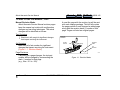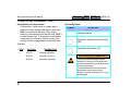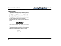
1
Search
Abbott Aeroset® Service Manual
TOC Go Back
89000-102
1.1 PRODUCT DESCRIPTION OVERVIEW
The Abbott Aeroset® System is an automated,
random-access clinical chemistry system. The
instrument uses a dual-pipetting system with a
maximum throughput of up to 2000 tests/hour. It
can be configured with up to 100 different assay
files utilizing photometric and potentiometric
methodologies. The potentiometric assays (Na+,
K+, and Cl-) are measured using an Integrated
Chip Technology™ (ICT™). The Abbott Aeroset
System will process routine and STAT samples
using independent Carousel and FastTrack™
Samplers.
1
General Data
1.1 PRODUCT DESCRIPTION OVERVIEW
1-1
Search
Abbott Aeroset® Service Manual
TOC Go Back
89000-102
1.2 HOW TO USE THIS MANUAL
The purpose of this manual is to provide
information useful for servicing the Abbott
Aeroset® System and is composed of seven (7)
chapters.
Chapter 1. General Data
Contains a product overview, information on
manual usage, manual revision marks, accident
prevention symbols, and system specifications.
Chapter 2. Troubleshooting
Contains procedures to be used by Field Service
Engineers/Representatives in identifying and
isolating problems. The procedures are
presented in probable cause and resolution
format.
Chapter 3. Parts Lists
Provides the Supplemental Tools and Supplies
list, exploded view drawings of all field spared
parts (and their configuration) which are indexed
to the item number, and description on the spare
Parts Lists (PL).
1
General Data
Chapter 4. Removal and Replacement
Contains Removal & Replacement procedures
that are indexed by number to related Parts Lists
in Chapter 3. For example, RR-A1.5 is the
Removal & Replacement procedure for Parts List
PL-A1, item #5.
Chapter 5. Verification Procedures
Contains adjustments, calibrations, checks, tests,
and additional procedures required to verify
instrument operation after repairs are complete.
Verification Procedures (VPs) are also used to
assist in troubleshooting.
Chapter 6. PM/Total Call
Contains preventive maintenance (PM)
procedures, Total Call procedure, and PM and
Total Call checklists for the instrument.
Chapter 7. Installation
Outlines the responsibilities of the Field Service
Engineer/ Representative (FSE/FSR) in setup of
the Abbott Aeroset System from pre-installation
to installation and relocation.
1.2 HOW TO USE THIS MANUAL
1-2
Search
Abbott Aeroset® Service Manual
TOC Go Back
89000-102
1.2 HOW TO USE THIS MANUAL, CONT.
Manual Revision Marks
Abbott Aeroset® Service Manual revision pages
keep the manual up to date with configuration
changes and servicing techniques. The actual
changes will be identified as follows:
A new title page with the revision log will be sent
with each change package. This list will contain
the page number of each changed or added page
along with the revision dash (-) number of that
page. Pages not listed are original pages.
Text Revisions
Black bar in left margin for significant changes
that impact servicing the instrument.
Art Revisions
Black bar left of art number for significant
changes that impact servicing the instrument.
(Figure 5 - 1. Revision Marks)
CUVETTE
SEGMENT
Cuvette
Pair Set
Page Revisions
If anything on a page changes, the text part
number will be changed by incrementing the
dash (-) number for that page
(e.g., from -101 to -102).
1
General Data
1.2 HOW TO USE THIS MANUAL
Spring
Revision
Mark
Art
Number
125010A
125702
Figure 1-1. Revision Marks
1-3
Search
Abbott Aeroset® Service Manual
TOC Go Back
89000-102
1.2 HOW TO USE THIS MANUAL, CONT.
Identification of Unique Items
If information, a procedure or a spare part is
unique to United States Field Service only, then
(US) is noted beside the item. If the item is
unique to International Field Service only, (INTL)
is noted beside item. If information, a procedure,
or spare part is unique to another country, the
country is listed in parenthesis beside that item.
Example:
ITEM
11
1
PART NO.
Special Symbols
SYMBOL
GND
DESCRIPTION
DEFINITION
Chassis GND (Ground) unless
otherwise stated.
Removal & Replacement Procedure
(RR).
Verification Procedure (VP).
2E12-01
Keyboard (English)
2E08-01
Keyboard (French)
ELECTROSTATIC SENSITIVITY
2E09-01
Keyboard (Spanish)
The Electrostatic Discharge symbol
identifies an activity or area where the
operator must wear a ground strap while
servicing the system.
Components sensitive to electrostatic
discharge such as printed circuit
boards, computer components, etc. may
be damaged.
General Data
1.2 HOW TO USE THIS MANUAL
1-4
Search
Abbott Aeroset® Service Manual
TOC Go Back
89000-102
1.2 HOW TO USE THIS MANUAL, CONT.
TSB/ISA Symbols
Two symbols are used to show areas or sections
in the service manual which have been affected
by a TSB or an ISA. Refer to actual TSB or ISA
for additional information.
These symbols are used to show a particular part
or area which has been, or has not been,
modified by the TSB number specified within the
symbol.
T 25
TSB 125-25 Installed
T 25
TSB 125-25 Not Installed
This symbol is used to identify the ISA containing
additional information about the part or area.
I 25
1
General Data
1.2 HOW TO USE THIS MANUAL
1-5
Search
Abbott Aeroset® Service Manual
TOC Go Back
89000-102
1.3 HAZARD TYPES
Introduction
Operation, maintenance, and servicing of the
Abbott Aeroset® Systems may expose individuals
to potential safety and health hazards. All work
must performed according to procedures
described in the Abbott Aeroset Operations or
Service Manuals or as directed by an Abbott
Technical Support Representative. This section
describes the types and locations of potential
hazards that could cause physical harm to
service personnel.
Hazard Signal Word Definitions and Icons
Hazard Signal Words
WARNING
Denotes a hazard which could result in moderate or
serious personal injury.
CAUTION
Denotes potential hazards that could result in minor
injury. Also used for conditions or activities that could
interfere with the proper functioning or performance
of the instrument.
NOTE: Denotes general operator or service
information that will not impact performance
or results if it is not observed.
DANGER
Denotes an Immediate hazard which, if not avoided,
could result in serious injury or death. This signal
word represents the highest level of any hazardous
situation.
1
General Data
1.3 HAZARD TYPES
1-6
Search
Abbott Aeroset® Service Manual
TOC Go Back
89000-102
1.3 HAZARD TYPES, CONT.
Hazard Icons
Safety hazard icons are used in this manual and
on the instrument labels to identify potentially
dangerous conditions or situations. In this
manual and on some instrument labels, text
accompanies the safety icon to describe the
hazard. For other instrument labels, the operator
or service technician is to refer to the manual for
specific information. All users of the instrument
must be familiar with the following messages:
ICON
RELATED TEXT
DESCRIPTION
WARNING: POTENTIAL BIOHAZARD.
Identifies an activity or area where the
operator may be exposed to potentially
infectious materials or substances.
DANGER: HIGH VOLTAGE.
Identifies high voltage areas over 600
volts.
WARNING: ELECTRICAL SHOCK
HAZARD.
Identifies the possibility of electrical
shock if procedural or engineering
controls are not observed.
CAUTION: HOT SURFACE
Identifies a part or component that
requires cooling before touching.
1
General Data
1.3 HAZARD TYPES
1-7
Search
Abbott Aeroset® Service Manual
TOC Go Back
89000-102
1.3 HAZARD TYPES, CONT.
Hazard Icons, Cont.
ICON
RELATED TEXT
DESCRIPTION
CAUTION: CLASS 2 LASER
PRODUCT
Warns against direct viewing into the
Bar Code Reader laser beam or
reflections of the beam from reflective
surfaces.
CAUTION: (ASSOCIATED TEXT)
Identifies an activity or an area that may
present a physical, mechanical, or
chemical hazard. The user must be
aware, alert, and cautious to prevent
physical injury.
WARNING: (ASSOCIATED TEXT)
See above. A more severe degree of
hazard than above.
1
General Data
1.3 HAZARD TYPES
1-8
Search
Abbott Aeroset® Service Manual
TOC Go Back
89000-102
1.4 BIOHAZARD SAFETY
WARNING: POTENTIAL BIOHAZARD
Consider all clinical specimens, reagent, controls,
and calibrators, etc. that contain human blood
and surfaces or components that have come into
contact with human blood as potentially
infectious. Wear gloves, lab coats, and safety
glasses, and follow other biosafety practices as
specified in OSHA Bloodborne Pathogen Rule
(29 CFR Part 1910.1030) or other equivalent
biosafety procedures.
Handling Spills
Clean up spills of potentially infectious materials
according to established biosafety practices. Use
the following generally accepted procedure for
cleaning such spills.
1. Absorb the spilled material with absorbent
towels or other absorbent materials.
2. Wipe the area with detergent solution
1
General Data
3. Wipe the area with an appropriate disinfectant
such as 2% chlorine bleach solution or a 0.1%
sodium hypochlorite solution.
Instrument Decontamination
Instruments must be decontaminated prior to
servicing or shipment. Complete the following
procedure unless an Abbott Technical Support
Representative provides other instructions
1. Cycle 10% chlorine bleach solution through
the fluid pathway (including the probe) that
contacted blood or products containing blood.
Allow the bleach solution to remain in the
system for a minimum of ten minutes.
2. Cycle water or buffer solution through the
system to rinse the affected components.
3. Remove any liquid material from the
instrument.
4. Rinse waste containers with the chlorine
bleach solution or other suitable disinfectants
before shipping or disposal.
1.4 BIOHAZARD SAFETY
1-9
Search
Abbott Aeroset® Service Manual
TOC Go Back
89000-102
1.4 BIOHAZARD SAFETY, CONT.
5. Wipe the surface of each instrument with a
detergent solution followed by an appropriate
disinfectant such as 0.1% sodium
hypochlorite (2% chlorine bleach solution).
Allow to air dry for a minimum of ten minutes.
Handling Waste
Dispose of all clinical specimens, reagents,
controls, calibrators, and other disposables that
may be contaminated according to local, state,
federal, and country regulations governing the
treatment of regulated medical waste.
Sharps
Sharps, such as contaminated probes, should be
placed in appropriately marked, punctureresistant containers before treatment and
disposal.
1
General Data
1.4 BIOHAZARD SAFETY
1-10
Search
Abbott Aeroset® Service Manual
TOC Go Back
89000-102
1.5 LASER SAFETY
CAUTION: CLASS 2 LASER PRODUCT
Denotes low-power, visible-light lasers or laser
systems. This class of laser do not normally
present a hazard to the eye because of normal
human aversion response such as blinking, eyemovement, and the like. However, like many
conventional light sources, they may present
some potential for hazard if viewed directly fort
extended periods of time.
During normal instrument operation, the inner
protective covers (and access door) are to
remain in place to prevent unintentional laser
light exposure. The inner protective covers (and
access doors) may be removed by qualified
personnel during servicing.
Do not remove or alter the inner protective cover
laser warning labels. They must remain legible.
The Class 2 Laser label on the instrument is
shown below in Figure 5 - 2. Laser Caution Label.
The label consists of black lettering on a yellow
background.
Figure 5-2. Laser Caution Label
1
General Data
1.5 LASER SAFETY
1-11
Search
Abbott Aeroset® Service Manual
TOC Go Back
89000-102
1.6 MECHANICAL/PHYSICAL SAFETY
WARNING: PUNCTURE HAZARD
The probe is sharp. Avoid contact with the tip of
the probe. Use protective gloves if necessary.
CAUTION: HOT SURFACE
Specific components and parts are very hot.
Allow the part or component to cool sufficiently
(generally 10 minutes) before servicing or
replacement. Use temperature resistant gloves if
required.
WARNING: LIFTING HAZARD
The Abbott Aeroset® System weighs 1500
pounds (680 kg). Obtain assistance when moving
and/or use appropriate lifting devices.
1
General Data
1.6 MECHANICAL/PHYSICAL SAFETY
1-12
Search
Abbott Aeroset® Service Manual
TOC Go Back
89000-102
1.7 ELECTRICAL SAFETY
WARNING: ELECTRICAL SHOCK HAZARD
Turn off the power to the instrument and
disconnect the power cord before replacing
fuses, printed circuit boards, and other electrical
parts and components. Replace only the fuses
that are externally accessible and labeled. Use
only replacement fuses of the specified type and
electrical rating.
Keep surfaces dry around the instrument and
electrical connectors.
Use approved power cords and electrical
accessories only, such as those supplied with the
instrument to protect against electrical shock.
Connect power cords to properly grounded
outlets only.
Do not disconnect any electrical connections
while the power is ON. Follow instructions for
correctly powering-down the instrument and all
connected equipment before performing service
or maintenance.
1
General Data
Shutdown Procedure
Prior to turning system power OFF, perform the
following procedure.
1. From the DATABASE screen:
! SHUTDOWN
2. SHUTDOWN CONFIGURATION screen is
displayed.
3. Check boxes for procedures to be performed.
a.For 24-hour operation, select:
" Clear Database, All Records
b.For partial-day operation, select:
" Change Water in Bath
" Wash Cuvettes
" Wash Probes with - 1% Alkaline Solution
" Wash ICT™ with ICT™ Cleaning Fluid
and ICT™ Reference Solution
" Drain and Fill IRef Cup
" Clear Database, All Records
4. Check Acid and Alkaline volumes and replace
if necessary.
1.7 ELECTRICAL SAFETY
1-13
Search
Abbott Aeroset® Service Manual
TOC Go Back
89000-102
1.7 ELECTRICAL SAFETY, CONT.
5. When SHUTDOWN CONFIGURATION is
complete, select:
! SHUTDOWN
If the Rotary Power Control Switch is set to
AUTO, system power will be shutdown after
the shutdown process.
High Voltage Hazard
DANGER: HIGH VOLTAGE
Ensure the power to the instrument is turned
OFF. A high voltage charge may remain on
electrical components such as laser connectors
or power supplies with the system power off. Use
an electrically insulated tool to disconnect the
charged part or component and short the charge
(both male pins) to the instrument chassis.
1
General Data
1.7 ELECTRICAL SAFETY
1-14
Search
Abbott Aeroset® Service Manual
TOC Go Back
89000-102
1.8 CHEMICAL SAFETY
CAUTION: CHEMICAL HAZARD
Wear safety glasses, chemical resistant gloves,
and a lab coat when handling the Abbott
solutions. These solutions may be potentially
harmful. Refer to the Material Safety Data Sheet
(MSDS) or the package insert for specific safety
information. In case of contact with the skin or
eyes, flush with water for at least 15 minutes. If
irritation persists or signs of toxicity occur from
exposure, seek medical attention immediately.
1
General Data
1.8 CHEMICAL SAFETY
1-15
Search
Abbott Aeroset® Service Manual
TOC Go Back
89000-102
1.9 SYSTEM SPECIFICATIONS
This section contains instrument dimensions,
space, computer and interface specifications,
electrical, environmental, printer, and optical
specifications and capacities requirements.
Clearances
Right:
31.5" (80 cm)
Left:
31.5” (80 cm)
Physical Dimensions
Rear:
20" (51 cm)
Analyzer
Above:
20" (51 cm)
Front:
36” (92 cm)
Width:
74.5" (189 cm)
Depth:
44.1" (112 cm)
Height:
43.5" (110.5 cm)
Weight:
1500 lbs. (680 kg)
For more detailed system dimension information,
see Chapter 7, Installation.
System Control Center (SCC)
Width:
24" (61 cm)
Depth:
18" (46 cm)
Height:
42.5" (108 cm)
(with monitor)
60.5” (154 cm)
Weight:
190 lbs. (86.5 kg) approx.
1
General Data
1.9 SYSTEM SPECIFICATIONS
1-16
Search
Abbott Aeroset® Service Manual
TOC Go Back
89000-102
1.9 SYSTEM SPECIFICATIONS, CONT.
Environmental Requirements
Computer and Interface Specifications
Processor:
Pentium®, 133 MHz, 16 MB RAM
Flat, level surface. No direct
sunlight or drafts. Remove from
sources of direct heat and
moisture. Do Not place next to a
heat or vibration-generating
device.
Hard Drive:
2.1 GB, EIDE bus interface to
CPU
Disk Drive:
3.5", 1.44 Mb, IDE bus interface to
CPU
Operator
Interface Display:
Full color VGA CRT, 17" diagonal
(43cm)
Minimum 15° C (59° F)
Maximum 32° C (89° F)
Keyboard:
101 Key, custom, IBM®
compatible
Printer:
80-column, parallel-port,
Centronix® connection
Host Interface
(System):
Bi-directional, RS-232 serial
communication port, 1200, 2400,
4800, or 9600 baud
NOTE: Instrument For Indoor Use Only
Location:
Temperature Operational:
Storage
Temperature:
Minimum 5° C (41° F)
Maximum 50° C (122° F)
Humidity:
15 - 80%
(non-condensing)
BTU Output:
6551 BTU/Hr.
Operating
Altitude:
6600 ft. (2000 m)
1
General Data
1.9 SYSTEM SPECIFICATIONS
1-17
Search
Abbott Aeroset® Service Manual
TOC Go Back
89000-102
1.9 SYSTEM SPECIFICATIONS, CONT.
Electrical Specifications
Analyzer
Required Measurement at 220V Outlet
U.S.
BREAKER
CLOSED
BREAKER
OPEN
Line 1 to Line 2 =
200 - 240 VAC
≤ 0.5 VAC
Line 1 to GND =
90 - 132 VAC
≤ 0.5 VAC
Line 2 to GND =
90 - 132 VAC
≤ 0.5 VAC
< 0.5 VAC
≤ 0.5 VAC
BREAKER
CLOSED
BREAKER
OPEN
Line to Neutral =
180 - 264 VAC
≤ 0.5 VAC
Line to Earth =
180 - 264 VAC
≤ 0.5 VAC
Neutral to Earth =
0.5 VAC
≤ 0.5 VAC
Neutral to Case =
< 0.5 VAC
≤ 0.5 VAC
GND to Conduit =
INTERNATIONAL
1
General Data
• Single phase, 180 - 264 VAC.
• 50/60 Hz ± 1%.
• 20 Amps - Nominal Operation.
Dedicated Power Line
• Separate Circuit breaker/Fuse.
• No other electrical devices can be supplied
from dedicated circuit breaker and power
lines.
Conduit or BMx (Flexible Metal Conduit
• No other electrical wires are present
Receptacle (U.S./Canada)
• The receptacle shall be a NEMA L6-30R
1.9 SYSTEM SPECIFICATIONS
1-18
TOC Go Back
Search
Abbott Aeroset® Service Manual
89000-102
1.9 SYSTEM SPECIFICATIONS, CONT.
Electrical Specifications, cont.
Printer
Power Connection
Power Requirements
Receptacle Mounting
The electrical box containing the
receptacle shall be mounted
within 12-ft. (3.7m) of the left side
of the instrument.
Power Cord
(U.S./Canada)
UL/CSA-approved, SJT type, 12
AWG, 250VAC.
Power Cord
(Outside U.S./
Canada)
IEC-309 approved for at least
30A, 250VAC and be of a type
meeting national electrical code
of the country of final destination.
Analyzer Connector:
(U.S./Canada)
The service connector shall be a
NEMA L6-30P.
Analyzer connector:
(outside U.S./
Canada)
IEC-309 approved for at least
30A, 250VAC and be of a type
meeting national electrical code
of country of final destination.
1
General Data
110VAC areas:
220VAC areas:
Frequency:
108 - 132VAC
198 - 264VAC
50/60 Hz ± 1%
Service Conn.
(U.S./Canada)
IEC 320, UL/CSA-rated
Service Connector:
(Outside U.S./
Canada)
Plug on power cord, mating with
utility service must be rated and
IEC-approved for at least 120VAC
and 0.4A (48 VA) and be of a type
meeting national electrical code of
country of final destination. The
plug is to be attached at final
destination if other than supplied
plug.
System Control Center
Power Requirements:
System power supplied from analyzer.
1.9 SYSTEM SPECIFICATIONS
1-19
Search
Abbott Aeroset® Service Manual
TOC Go Back
89000-102
1.9 SYSTEM SPECIFICATIONS, CONT.
Sample Bar Code Specifications
BAR CODE
READER
Sample
Reagent
1
General Data
Measurement Methods
SUPPORTED SYMBOLOGY
Codabar
Code 3 of 9
Code I 2 of 5
Code 128, Subset A, B, and C
4 - 20 Characters, No Checksum
or Start/Stop Characters
Type
Photometric
Potentiometric
Throughput
Photometric and ICT™: Up to 2000/hr.
Photometric only: Up to 1600/hr.
ICT only: Up to 600/hr
2D Labels
PDF - 417
1D Labels
Code I 2 of 5
Code 128
Codabar
Code 3 of 9
1.9 SYSTEM SPECIFICATIONS
1-20
Search
Abbott Aeroset® Service Manual
TOC Go Back
89000-102
1.9 SYSTEM SPECIFICATIONS, CONT.
Optical Specifications
Capacities
Lamp Type:
Tungsten - Halogen
Wavelength Range:
340 - 804 nm
Wavelengths Measured:
(in nanometers)
340, 380, 404, 412, 444,
476, 500, 524, 548, 572,
604, 628, 660, 700, 748,
and 804 nm
Photometric Range:
0.1 to 3.0 Abs (converted
to 10 mm light path length)
Light Path Length:
5 mm
Linearity:
Within ± 2% @ 2.0 Abs
1
General Data
Data Storage
Data Base Records:
QC:
Error Log:
Carousels
Reaction:
Cal/Control:
Sample:
Stat:
Reagent:
Seg. A:
Seg. B:
Seg. C:
Seg. D:
1.9 SYSTEM SPECIFICATIONS
8000
150/Level
200
330 Reaction Cuvettes
45 Positions
30 Positions
1 Position
56 Positions/Carousel
12 Positions
12 Positions
12 Positions
20 Positions
1-21
Search
Abbott Aeroset® Service Manual
TOC Go Back
89000-102
1.9 SYSTEM SPECIFICATIONS, CONT.
Sample Carrier & Sample Carrier Tray
Reagent Containers
Sample Carrier:
5 Samples per Carrier
Large:
90 mL
Sample Carrier Tray:
10 Sample Carriers per tray
Small:
50 mL (requires adapter)
FastTrack™ Capacity:
200 samples
(4 Sample Carriers)
100 mL:
100 mL
20 mL:
Round (requires adapter)
Sample Vessels
Sample Vessel
Bulk Solutions
Ext. Diam (mm) Hgth (mm)
10-mL (16 mm) tube:
15.4 ± 0.3100
7-mL (16 mm) tube:
15.4 ± 0.375
7-mL (13 mm) tube:
12.4 ± 0.2100
5-mL (13 mm) tube:
12.4 ± 0.175
Sample Cup (2 mm)
Bulk Solution
ICT™ Ref. Sol.:
Alkaline Wash:
Acid Wash:
Method Volumes
Sample Dispense:
Sample Aspiration:
Sample ICT™
Dispense:
Reagent Dispense:
Reagent Aspiration:
1L
500 mL
500 mL
2-35 µL/Test
Sum of sample Dispense
15 µL
20-345 µL/test
Sum of Reagent Dispense
Liquid Waste Container:
1
General Data
1.9 SYSTEM SPECIFICATIONS
Approx. 8 L
1-22
Search
Abbott Aeroset® Service Manual
TOC Go Back
89000-102
1.9 SYSTEM SPECIFICATIONS, CONT.
Fluidics
TUBING TYPE
Drainage
ID
OD
LGTH.
Deionized Water
High Pressure Hose
9mm
5mm
≤5 M
Low Concentrate
Waste
High Pressure Hose
15mm
23mm
≤5 M
Overflow
High Pressure Hose
12mm
18mm
≤5 M
Bath Water Drainage
High Pressure Hose
12mm
18mm
≤5 M
High Concentrate
Waste
Silicon Rubber
6mm
12mm
≤5 M
1
General Data
Water Drainage (Total During Analysis)
47.5 L/hr
Maximum Drainage
70 L/hr
High Concentrate Drainage
2.5 L/hr
1.9 SYSTEM SPECIFICATIONS
1-23