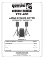
1
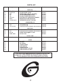
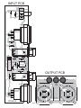
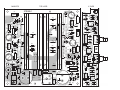
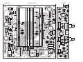
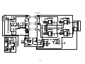
SERVICE MANUAL
XTR-400
ACTIVE SPEAKER SYSTEM
SUBWOOFER / SATELLITES
CONTENT’S:
Cautions, Connections, & Operations :....................................Page 2-4
Specifications:..............................................................................Page 4
Parts Lists:....................................................................................Page 5
PCBs:..........................................................................................Page 6-8
Schematics....................................................................................Page 9
Gemini Sound Products Corp.
120 Clover Place P.O. Box 6928
Edison, NJ 08818-6928
732-738-9003 (Phone) • 732-738-9006 (Fax)
(1)
(2)
OUTPUT SECTION:
INTRODUCTION:
Disconnect unit from the AC power source before making any connections.
Congratulations on your purchase of an XTR-400 speaker system
engineered & manufactured by Gemini Sound Products. This state of the
art speaker system is backed up by a three-year warranty. The XTR-400
offers ultimate fidelity, power handling, and an array of features that makes
it a highly versatile, compact, self contained & powered speaker system.
SPEAKER OUTPUTS (3): The speaker output connectors are Speakon™
connectors that will accept cables with Speakon™ connectors. (These
cables must be purchased separately) The subwoofer is already connected
internally, so you don’t have to worry about connecting it to the amplifier.
FEATURES:
•
•
•
•
•
•
•
•
•
•
•
AC POWER SECTION:
Active self-powered 400W rms tri-amp design.
One 15-inch bandpass subwoofer. Features top-hat hardware for pole mounting of a
satellite speaker and metal corner protectors.
Two high quality satellite speakers featuring 10-inch woofers and dual piezo horns housed in
trapezoidal cabinets. Satellite speakers are uniquely designed for placement on stands or for use
as floor monitors, and protected by full front metal grill and metal corners.
Built-in active optimized crossovers.
Sensitivity/Volume controls.
Satellites equipped with reliable Speakon™ connectors for exceptional sound.
(cables must be purchased separately)
Signal Ground Lift Switch for achieving the quietest possible hum-free operation.
Airflow controlled by variable speed fan for maximum cooling and quietest possible operation.
Mono or Stereo operation.
AC line voltage selector switch allows reconfiguring amplifier for either 110-120V or 220240V AC lines.
Compact design featuring large metal handles and casters for ease in transporting.
POWER SWITCH (8): turns the unit on and off.
POWER LED (9): the power LED lights when the power is on.
FUSE (4): replace with proper type and rating.
AC INLET (6) is used to attach the power cord to the unit.
AC LINE VOLTAGE SELECTOR SWITCH (5) allows reconfiguring
amplifier for either 110-120V or 220-240V AC lines.
OPERATION:
STEREO OPERATION:
CAUTIONS:
The unit has two channels for stereo operation. Each channel provides a
separate signal at the speaker outputs. The following instructions are
for use with 8W speakers of matched power ratings. We suggest only
using the speakers that come with the unit.
1. All operating instructions should be read before using this equipment.
2. To reduce the risk of electrical shock, do not open the unit. There are,
NO USER REPLACEABLE PARTS INSIDE. Please refer servicing to a
qualified Gemini Sound Products service technician.
1. With the power OFF, connect your input cables from your music source
(such as your mixer) to the Channel 1 and Channel 2 INPUTS using the
XLR INPUT JACKS (1) or 1/4" PHONO INPUT JACKS (2).
In the USA: If you experience problems with this unit, please call 1 (732) 738-9003 for
Gemini Customer Service. Do not attempt to return this equipment to your dealer.
3. Do not expose this unit to direct sunlight or to a heat source such as a
radiator or stove.
2. Connect your speakers to the Channel 1 and Channel 2 SPEAKER
OUTPUTS (3).
4. This unit should be cleaned only with a damp cloth. Avoid solvents or
other cleaning detergents.
3. With the SENSITIVITY/VOLUME CONTROLS (10) of both channels
set to zero (fully counter clockwise), turn the POWER SWITCH (8), ON.
Okay, now try playing some music and/or talking into your microphone,
and set the level of your input as high as you think you’ll need it. This way
it will be as high above the amplifier’s noise floor as possible so you’ll get
the best possible sound with the least amount of noise. Now play some
music and listen for audible distortion. If you do hear distortion decrease
the output level using the SENSITIVITY/VOLUME CONTROLS (10).
5. When moving this equipment, it should be placed in its original carton
and packaging. This will reduce the risk of damage during transit.
6. DO NOT EXPOSE THIS UNIT TO RAIN OR MOISTURE.
7. DO NOT USE ANY SPRAY CLEANER OR LUBRICANT ON ANY
CONTROLS OR SWITCHES.
MONO OPERATION:
Connect your MONO signal to the Channel 1 input (1 or 2). Now create a
link by connecting the remaining Channel 1 input to a Channel 2 input
(1 or 2) using a standard balanced cable (may be purchased separately).
You can adjust the level of each satellite speaker using it’s channel’s
SENSITIVITY/VOLUME CONTROL (10).
CONNECTIONS:
INPUT SECTION:
There are two parallel input connectors (one female XLR and one 1/4” jack) per
channel. Either can be used as an input or as a link to chain amplifiers.
USING THE SIGNAL GROUND LIFT SWITCH:
XLR INPUT JACKS: XLR INPUT JACKS (1) electronically balanced
inputs accept a standard XLR male connector. Pin 1 = shield/ground, pin
2 = hot or positive (+) and pin 3 = cold or negative (-).
Depending on how your sound system is hooked up, sometimes applying
the ground will create a quieter signal path. Sometimes lifting the ground
can eliminate ground loops and that annoying hum to give you quieter and
cleaner overall sound.
1/4" PHONO INPUT JACKS: 1/4" PHONO INPUT JACKS (2) accept a
balanced as well as an unbalanced line. The unbalanced line uses a
standard tip-sleeve connection. The tip is positive and the sleeve is
negative/ground. The balanced line uses a tip-ring-sleeve connection.
Tip = hot or positive (+), ring = cold or negative (-), and sleeve = shield/ground.
1. With the power amp ON, listen to the system in idle mode (no music or
signal) with the ground ON. The SIGNAL GROUND LIFT SWITCH (7) will
be in the left position.
SENSITIVITY/VOLUME CONTROLS: SENSITIVITY/VOLUME CONTROLS
(10) control the input levels for each channel of the 2 satellite speakers.
The volume level of the subwoofer is controlled automatically to match the
volume levels of the satellite speakers. It will always maintain a perfect
balance to give you incredible sound quality!
SIGNAL GROUND LIFT SWITCH: SIGNAL GROUND LIFT SWITCH (7)
is used to lift the balanced input connectors’ ground/shield from the
amplifier’s ground. When the signal ground lifted, the sound source
disconnects from the amplifier’s ground preventing ground loops which
can generate hum and noise. See the Signal Ground Lift Switch
Instructions for more detail.
2. Turn the power OFF before moving the SIGNAL GROUND LIFT SWITCH (7).
Now lift the ground by moving the SIGNAL GROUND LIFT SWITCH (7)
to the right. Turn the power back ON and listen to determine which position
makes the overall sound quieter with the least amount of noise and hum.
CAUTION: DO NOT DISCONNECT THE AC GROUND ON THE POWER AMPLIFIER IN ANY WAY.
THIS CAN BE VERY HAZARDOUS!!
(3)
SETUP:
SPECIFICATIONS:
There are various ways to set up this system:
BASIC SETUP:
Okay, this is your basic setup, perfect for small parties and venues. The
ideal location for your subwoofer is close to a wall or in a corner. This
will give you the fullest bass response. Your 2 satellite speakers can be
placed up on stands on each side (stands must be purchased separately).
TWO-SYSTEM SETUP:
This setup is perfect for larger venues. This setup requires 2 XTR-400
systems. This will give you a total of 800 watts rms! Place a subwoofer
on each side to the left and right. Using the high-hat hardware and
connecting pole (which can be purchased separately), place the
pole in the high-hat socket on the subwoofer, and a satellite speaker on
top of the pole. The 2 remaining satellite speakers may be used as either
floor monitors, or placed on stands elsewhere in the room giving you a
louder and fuller sound.
Each speaker system in this setup must be used in MONO mode (see
Mono section). Connect the system that is on the left side of the audience
to the LEFT channel of your mixer, and the system that is on the right side
of the audience to the RIGHT channel of your mixer.
ACTIVE SPEAKER SYSTEM SUBWOOFER/SATELLITES
The XTR-400 features a unique design for ease in transporting. The 2
satellite speakers conveniently fit into a special recessed section of the
subwoofer and are securely fastened using a strap that attaches to the
handles (included).
Subwoofer XTR-400SUB:
Amplifier’s Output Power:.........................230 Wrms on subwoofer channel
Frequency response:……………………...........................….32 Hz - 100 Hz
Components:………………………...........................……………..15" woofer
Features:
Efficient band-pass cabinet design
Large metal handles
Metal protection corners
Four 2" wheels
Amplifier assembly on the back
35mm standmount cap on top
Black carpet finish
Rubber feet
Dimensions:..............................................................WxDxH: 20"x31"x24.5"
(508 x 788 x 622 mm)
Weight:…………………............................……………………..96 lbs (44 kg)
Satellites GT-1002s:
Amplifier’s Output Power:..........................2x85 Wrms on satellite channels
Frequency response:…………............................………….100 Hz – 20 kHz
Components:….…………...........................……………………….10" woofer
6” dual piezo horn
Features:
Trapezoidal cabinet
Full front protective metal grill
Metal protection corners
35 mm standmount cup on the bottom
Black carpet finish
Rubber feet
Neutrik Speakon connector
Dimensions:……….……..............................…….W x D x H 12.5" x 9" x 18"
(318 x 229 x 458 mm)
Weight:……………………...........................………………18 lbs (8 kg) each
Total System:
Maximum SPL, continuous:……...........................……………………120 dB
Sensitivity………………………...........................……………………. 1 Vrms
Input Impedance………...............10 kOhm unbalanced/20 kOhm balanced
Features:
Balanced XLR and 1/4" Jack inputs
Neutrik Speakons on Satellite Channels’ outputs
Active electronic X-over (Fx=100 Hz)
Variable speed fan
Individual channel Sensitivity/Volume controls
Signal Ground lift switch
110-120 VAC / 220-240 VAC switchable
Total Weight:……………............…...............………………...132 lbs (60 kg)
SPECIFICATIONS AND DESIGN ARE SUBJECT TO CHANGE WITHOUT
NOTICE FOR PURPOSE OF IMPROVEMENT.
SHOULD YOU EXPERIENCE ANY DIFFICULTIES OR PROBLEMS,
PLEASE CALL: 1 (732) 738-9003 FOR GEMINI CUSTOMER SERVICE.
(4)
PARTS LIST:
Item #
Designators
Description
Part Number
1
2
3
4
5
6
7
8
ZD3, ZD2
D3, D1, D2
ZD1
Q1
Q2
C18, C13
REC1
U3, U2, U4, U1
MAIN PCB:
ZENER DIODE 1/2W 12V (RD12EB2)
SILICON DIODE 1N4148
ZENER DIODE 1/2W 24V (RD24EB2)
SILICON TRANSISTORS 2SC1815
SILICON TRANSISTOR 2SC4793
µ/50V
ELECTROLYTIC CAPACITORS 6800µ
BRIDGE RECTIFIER KBPC804W
INTEGRATED CIRCUIT TDA7294V
079-012
079-003
079-020
076-003
076-100
050-198
086-019
074-189
1
2
3
VR1, VR2
LD1
IC1, IC3, IC2
1
2
3
4
SW1
IC1
X3, X2
XLR2, XLR1
1
X1, X2
1
2
3
4
5
6
7
8
CROSSOVER PCB:
ROTARY VR 10KA L:15MM
φ
LED (GREEN) 5φ
INTEGRATED CIRCUIT NJM4558DD (BA15218,M5218AP)
INPUT PCB:
SLIDE SWITCH SV70050
071-228
080-086
074-163
φTRS 1/4" BAL
PHONE JACK 6.3φ
XLR XLF-3PH
081-030
074-163
092-078
092-069
OUTPUT PCB:
SPEAKON™ CONNECTORS NL4MP
092-149
OTHER:
AC CORD
AC INLET
DC FAN 24V
TRANSFORMER
SLIDE SWITCH
POWER SWITCH
FUSE VBS UTE 3.15A 250V
FUSE VBS UTE 6.3A 250V
093-369
092-105
001-613
059-247
081-023
083-121
100-068
100-071
INTEGRATED CIRCUIT NJM4558DD (BA15218,M5218AP)
In the USA: If you should experience problems with this unit,
please call 1 (732) 738-9003 for Gemini Customer Service.
Do not attempt to return this equipment to your dealer.
(5)
INPUT PCB
SW1
C1
R5
XLR1
R1
R2
X2
X1
R6
C5
R8
C3
C2
IC1
R7
R4
C4
R9
OUTPUT PCB
R3
+
X3
+
G
XLR2
XTR400-4
XTR400-3
Page 6
MAIN PCB
TOP LAYER
X-OVER
XTR400-2
XTR400-1
LD1
L4
C14
X3
R16
C19
R19
R37
15
RED/BLK
C27
RED
C17
C5
R7
R2 R3 R4
C29
C11
C7
IC2
1
X2
J9
C13
U3
R20
X10
J3
C8
R3
R15
C4
R1
R14
R14
R13
R8
R26
R21
R30
J1
J2
C16
1
R31
J5
R36
C21
R16
C23
BLK
R23
C25
R6 C6
X11
15
1
RED
J10
X2
U4
R22
R17
R27
1
C24
U2
R18
X1
C10
C2
L3
IC3
D2
R12
C20
R21
C6
C9
R9
R4
X12
R32
J8
C8
C15
C5
L1
C22
C7
15
U1
VR2
R15
C1
R11
C1
R18
VR1
R13
ZD2
R25
C12
X9
C14
C31
J1
J6
X4
ZD1
C3
C9
R5
R12
R38
C28
J4
R17
R7
Q1
J3
R10
C11
C10
15
J2
R35
R24
L2
R10
R29
C2
D3
R6
C12
RED
X8
R5
C32
C30
R19
R20 X3
REC1
IC1
+
AC
C13
AC
D1
-
R2
X6
BLK
R33
R34
ZD3
X5
BLK
R1
C3
R8
R9
C26
Q2
C4
R22
X1
X4
C18
J7
RED
X7
R11
R28
X13
BLK
1
MAIN PCB
BOTTOM LAYER
X-OVER
XTR400-2
XTR400-1
LD1
L4
C14
X3
R16
C19
R19
R37
15
RED/BLK
RED
C17
R7
C5
C29
C27
R2 R3 R4
C7
C11
J9
IC2
1
X2
R3
U3
R20
C13
C8
X10
J3
C4
R15
R8
R1
R14
R14
R13
R26
R21
R30
J1
J2
C16
1
J5
C23
BLK
R23
X2
X11
C25
1
RED
J10
R17
R6 C6
C2
U4
R22
15
U2
R27
1
C24
X1
C10
R36
C21
R16
IC3
D2
R12
L3
R18
R4
C20
R21
R9
C6
C9
X12
R32
J8
C8
C15
C5
L1
C22
R31
C7
15
U1
VR2
R15
C1
R11
C1
R18
VR1
R13
ZD2
R25
C12
X9
C14
C31
J1
J6
X4
ZD1
C3
C9
R5
R12
R38
C28
J4
R17
R7
Q1
J3
R10
C11
C10
15
J2
R35
R24
L2
R29
C2
D3
R6
C12
RED
X8
R5
C32
C30
R19
R20 X3
REC1
IC1
+
AC
C13
AC
D1
-
R2
X6
BLK
R33
R34
ZD3
X5
BLK
R1
C3
R8
R9
C26
Q2
C4
R11
R10
X4
C18
J7
RED
X7
R22
X1
R28
X13
BLK
1
SCHEMATIC
X2
7
7
6
6
R9
13K 1%
C7
10uF25V NP
5
CH.1 (L) INPUT
2
1
1
MAIN PCB
X3
1
1 CH.1 (L) INPUT
2
2
3
3
4
4 SUB INPUT (+)
C6 10pF
C7
10pF
8
+ 12V
C6
10uF25V NP
C4
.047uF5%
3
CH.2 (R) INPUT
2
CH.1 (L) OUTPUT
C3
.047uF5%
VR2
10KA
CH.1 (L)
VOLUME
CONTROL
- 12V
SUB OUTPUT (+)
2
R6 26.7K 1%
R8
39.2K 1%
R11 26.7K 1%
1
3
R17 13K 1%
IC1A
NJM4558DD
- 12V
6
R10
39.2K 1%
R14
10K 1%
R21 13K 1%
R15
13K 1%
7
5
R22
13K 1%
R12
60.4K 1%
R18
10K 1%
+E
R4
1K 1%
4
4
X3
X12
1
+ 12V
5.1K
R12 13K 1%
C10
2200pF
1
2
2 CH.2 (R) INPUT
3
3
4
4 SUB INPUT (-)
U2
C9
22uF25V
IN -
3
IN +
4
IN+MUTE
+Vs
MUTE
9
STBY
1
R17
5.1K
+PWVs
10
OUT
BOOTSTRAP
-Vs
STBY-GND
-PWVs
C14
0.1
13
SUBWOOFER
OUTPUT (+)
7
14
R10 8R2 1W
6
L2 1.0uH
C11 22uF50V
8
+E
R14
1K 1%
TDA7294V
2
R8 5.1K
X1
RED
R13 13K 1%
C4
390pF
C2
0.1uF100V
15
U1
C8
10uF25V
IN -
3
IN +
4
IN+MUTE
R15
5.1K
+PWVs
+Vs
10
MUTE
9
STBY
1
R18
5.1K
TDA7294V
2
OUT
BOOTSTRAP
-Vs
STBY-GND
-PWVs
13
CH.1 (L)
OUTPUT
7
14
R3 8R2 1W
6
L1 1.0uH
C5 10uF50V
8
X2
RED
OUTPUT PCB
18AWG RED
C1
0.1uF100V
15
X1 NL4MP
P1
1+
RED
1OUTPUT
C15
0.1
R16
5.1K
2+
CH.1 (L)
8
+ 12V
R9
IC3B
NJM4558DD
R2 13K 1%
CH.2 (R) OUTPUT
IC3A
NJM4558DD
4
R1
39.2K 1%
- 12V
1
3
R3 39.2K 1%
R4 39.2K 1%
7
5
IC2A
NJM4558DD
SUB OUTPUT (-)
C11
0.033uF5%
R23
5.1K
X1
R6
13K 1%
+ 12V
C10
0.1
- 12V
C12
.047uF 5%
VR1
10KA
CH.2 (R)
VOLUME
CONTROL
6
5
C32
22uF25V
R22
5.1K
R20
5.1K
7
R16
2.4K
C14
100uF16V
IC1B
NJM4558DD
LD1
GRN
1 +12V
2
2
3
3 -12V
C30
10uF25V
R21
5.1K
C28 10pF
R38 26.7K 1%K
C9
0.1
Ends
striped
15mm
C24
2200pF
U4
R27 13K 1%
IN -
+PWVs
3
IN +
+Vs
4
C25
22uF25V
IN+MUTE
10
MUTE
9
STBY
1
STBY-GND
2R26 26.7K 1%
OUT
BOOTSTRAP
-Vs
-PWVs
C16
0.1
13
SUBWOOFER
OUTPUT (-)
7
14
R36 8R2 1W
6
L3 1.0uH
C21 22uF50V
8
+E
R32
1K 1%
TDA7294V
2
R30 5.1K
X11
BLACK
C22
390pF
C23
0.1uF100V
15
2+
C27 10pF
18AWG BLACK 45sm
+E
R25
1K 1%
R19
5.1K
18AWG RED 45sm
Twisted pair to Subwoofer terminal
R35 5.1K
U3
R31 13K 1%
C20
10uF25V
2
IN -
3
IN +
4
IN+MUTE
10
MUTE
9
STBY
1
STBY-GND
TDA7294V
+PWVs
+Vs
OUT
BOOTSTRAP
-Vs
-PWVs
P2
BLACK
13
CH.2 (R)
OUTPUT
7
14
R37 8R2 1W
6
L4 1.0uH
C19 10uF50V
8
15
X10
RED/BLACK STRIP
C29
0.1uF100V
C17
0.1
POWER PCB
P1 SW3
-E
SW-POWER
BRN
-E
T1
+E
C4 270
R3 10K 1%
T
R
S
R4 10K 1%
6
5
X3 TRS 1/4" BAL
R5 510
C2
270
7
IC1B
NJM4558DD
+ 12V
1
3
6
5
4
5
SW1
"Signal ground lift"
6
7
6
E
N
ORG
C5 270
- 12V
R8 10K 1%
5
3
2
2
1
AC INLET
1
CH.2 (R) OUTPUT
+E
RED
2
X7
REC1
KBPS10-02
C13
6800uF50V
4
R7
68
RED
Q2
2SC4793
Q1
2SC1815
X4
T
D2
1N4148
ZD1
24V 0.5W
C12
4.7uF50V
C3
220uF25V
FAN
24 Vdc
FAN1
24Vdc/0.19A
C31
100uF16V
ZD2
12V 0.5W
R28 1.2K 3W
X13 BLACK
To CHASSIS
X5
8.2K
C26
100uF16V
ZD3
12V 0.5W
C18
6800uF50V
To POWER
TRANSFORMER
WHT
R1
+12V
R29 1.2K 3W
To POWER
TRANSFORMER
BLK
2.4K
R5
2.4K
CH.1 (L) OUTPUT
4
3
X8
230v
R2
BLACK
To CENTER TAP
POWER TRANSFORMER
SW4
VOLTAGE SELECTOR
115v
C1 0.047uF
4
7
X6
BLU
F
L
X1
R7
10K 1%
D1 1N4148
P3
3
FUSE
6.3A / 110-120V
3.15A / 220-240V
R9 10K 1%
XLR2
XLF-3PH
1
1
C101
3
2
P2
-E
-12V
BLACK
To SPEAKER
OUTPUTS
+ 12V
8
3
XLR1
XLF-3PH
R6 10K 1%
T
R
S
R1 10K 1%
2
1
3
X2 TRS 1/4" BAL
CH.2 (R)
INPUT
18AWG BLACK
18AWG BLACK
IC1A
NJM4558DD
4
C3
270
1-
- 12V
R2
10K 1%
Page 9
OUTPUT
CH.2 (R)
R24
8.2K
D3
1N4148
R19
39.2K 1%
INPUT PCB
1+
X9
1
R5
39.2K 1%
CH.1 (L)
INPUT
X2 NL4MP
P3
RED/BLACK STRIP
R33 5.1K
C13
100uF16V
C2
.047uF 5%
-E
-E
C1 0.033uF5%
- 12V
R7
39.2K 1%
R20
22.1K 1%
R34 5.1K
IC2B
NJM4558DD
2-
18AWG RED/BLACK STRIP
3
R13
60.4K 1%
2
4
1
C5
.1uF 5%
18AWG BLACK
6
8
2
C8
.1uF 5%
2
3
R11
22.1K 1%
1
4
+ 12V
2
5
X4
X-OVER PCB