1
Back
Your Local Agent/Dealer
9-52 Ashihara-cho,
Nishinomiya, Japan
Telephone :
0798-65-2111
Telefax :
0798-65-4200
All rights reserved.
Printed in Japan
FIRST EDITION : OCT. 1993
N3
PUB.No. OME-55722
( TENI
) FS-1562-15/25
: JUL. 15,2003
*00080552800*
*00080552800*
*00080552800*
*OME55722N30*
*OME55722N30*
*OME55722N30*
SAFETY INSTRUCTIONS
"DANGER", "WARNING" and "CAUTION" notices appear throughout this manual. It is the
responsibility of the operator of the equipment to read, understand and follow these notices. If you have any questions regarding these safety instructions, please contact a
FURUNO agent or dealer.
The level of risk appearing in the notices is defined as follows:
DANGER
This notice indicates a potentially
hazardous situation which, if not
avoided, will result in death or
serious injury.
WARNING
This notice indicates a potentially
hazardous situation which, if not
avoided, could result in death or
serious injury.
CAUTION
This notice indicates a potentially
hazardous situation which, if not
avoided, could result in minor or
moderate injury, or property damage.
i
i
DANGER
WARNING
Do not work inside the equipment unless totally familiar
with electrical circuits.
Do not operate the equipment with wet
hands.
Electrical shock can result.
Hazardous voltage which will
cause death or serious injury
exists at the following
locations:
Keep heater away from equipment.
Heat can alter equipment shape and melt
the power cord, which can cause fire or
electrical shock.
• Transceiver unit
• Antenna and antenna
coupler (both at TX)
Any repair must be done by a licensed
radio technician.
Improper repair work can cause fire or
electrical shock.
HAZARDOUS VOLTAGE
is present at these points.
ANTENNA COUPLER
CAUTION
Use the proper fuse.
Use of a wrong fuse can result in fire or
permanent equipment damage.
WARNING
Do not use the equipment for other than
its intended purpose.
Do not disassemble or modify the
equipment.
Personal injury can result if the equipment
is used as a chair or stepping stool, for
example.
Fire, electrical shock or serious injury
can result.
Do not place objects on the top of the
equipment.
Turn off the power immediately if water
leaks into the equipment or the equipment is emitting smoke or fire.
The equipment can overheat or personal
injury can result if the object falls.
Continued use of the equipment can cause
fire or electrical shock.
Do not place liquid-filled containers on
the top of the equipment.
Fire or electrical shock can result if a liquid
spills into the equipment.
ii
LIST OF CONTENTS
INTRODUCTION .................................................................................................. iv
Specifications of MF/HF Radiotelephone model FS-1562 ...................................... v
Chapter 1
1.1
1.2
1.3
1.4
1.5
1.6
1.7
1.8
1.9
1.10
1.11
1.12
Chapter 2
OPERATION ................................................................................ 1.1
SYSTEM SET-UP ........................................................................ 1.1
Front View of Transceiver Unit .................................................... 1.2
Power Supply Unit ....................................................................... 1.4
Starting operation ......................................................................... 1.5
Selecting Frequency ..................................................................... 1.5
Transmitting ................................................................................ 1.10
Distress Call on 2182 kHz .......................................................... 1.11
In the Event of Antenna Coupler Failure.................................... 1.13
DSC Distress Calling.................................................................. 1.13
Receiving .................................................................................... 1.14
Frequency Scan .......................................................................... 1.15
Frequency Sweep........................................................................ 1.16
OPERATION of OPTIONAL DEVICES ..................................... 2.1
2.1
2.2
2.3
Telex Communication................................................................... 2.1
Intercom........................................................................................ 2.2
Remote Station ............................................................................. 2.2
Chapter 3
3.1
3.2
CHANGING SYSTEM SETTING .............................................. 3.1
SYSTEM SETUP ......................................................................... 3.1
CUSTOMIZING BY OPERATOR ............................................... 3.1
Chapter 4
4.1
4.2
4.3
4.4
4.5
MAINTENANCE ......................................................................... 4.1
Weekly Checks ............................................................................. 4.1
Diagnostic Test ............................................................................. 4.1
LCD/Keyboard Test & ROM Version No. Confirmation ............. 4.3
Antenna Coupler Test ................................................................... 4.4
Maintenance ................................................................................. 4.5
Chapter 5
5.1
5.2
5.3
TROUBLESHOOTING ............................................................... 5.1
Troubleshooting List ..................................................................... 5.1
Error Indication ............................................................................ 5.3
Replacing Fuses ............................................................................ 5.3
APPENDIX ........................................................................................................ AP.1
Declaration of conformity to type
iii
INTRODUCTION
FURUNO Electric Company thanks you for selecting the FS-1562 MF/HF SSB Radiotelephone.
We are confident you will discover why FURUNO has become synonymous with quality and
reliability. To get maximum performance from your unit, please carefully read and follow the
recommended procedures for operation and maintenance.
The FS-1562 is an all-purpose radiotelephone system especially designed for marine mobile
communication in the frequency range 1.6 to 27.5 MHz. All ITU channels are preprogrammed.
In addition, TX/RX frequencies can be preprogrammed into a E2 PROM having a capacity of
200 frequency pairs.
There are two types of the FS-1562: FS-1562-15 (150 Wpep) and FS-1562-25 (250 Wpep),
where pep is peak envelope power, the unit for addressing an output power in a Single Sideband
(SSB) transmitter.
•
•
Installation information is contained in the installation manual.
System initialization after installation is described in the service manual.
Features
•
•
•
•
•
•
•
•
•
•
GMDSS operation: DSC and NBDP connections
2182 key provides for immediate selection of 2182 kHz (at FULL power automatically)
Scan/Sweep receiving function
PROM stores all ITU SSB and TELEX frequencies
Dummy load (in the Antenna Coupler) permits checking of transmitter
Effective noise blanker cancels pulse noise
Advanced “voice” detecting type squelch circuit filters out noise
Remote station (RB-500) optionally available
System diagnostics program
The AC FAIL Board (option) functions to reduce Tx power automatically when AC power
fails (only FS-1562-25).
Notes
1. Use a battery having sufficient capacity (more than 120 AH for 150 W set, 200 AH for 250 W
set). Otherwise, battery cannot provide sufficient transmission power.
2. Handle the microphone carefully. Heat, humidity and shock will affect performance.
3. Do not adjust the potentiometers inside the unit. Improper adjustment may cause serious
damage.
iv
Specifications of MF/HF Radiotelephone model FS-1562
The model FS-1562-15/25 complies with the following rules and regulations:
-
IMO A.421(XI), A.610(15), A613(15), A.694(17)
International Convention on Safety of Life at Sea 1974, as amended 1988 (GMDSS Conference)
ITU Radio Regulations
ETS 300 373
IEC 1097-9 draft, IEC 945 General Requirements
EC EMC Directive for CE marking requirements
Other relevant rules
GENERAL
Communication System
Simplex or semi-duplex
Frequency Range
1.6 to 27.5 MHz (transmit), 0.1 to 30 MHz (receive)
Frequency Resolution
Transmit: 100 Hz
Class of Emission
J3E
H3E
J2B
F3C
Receive: 10 Hz
SSB, suppressed carrier, signal channel containing analogue information, telephony;
when 2182 kHz is first selected, H3E is set.
SSB, full carrier, signal channel containing analogue information.
for DSC, NBDP; SSB, suppressed carrier, signal channel containing quantized
or digital information with the use of a modulating sub-carrier, telegraphy for
automatic reception
weather facsimile, reception only
Frequency Error
±10 Hz (Both Transmitter and Receiver)
Number of Channels
Custom channels: 200 max programmed by Furuno authorized service representatives
ITU SSB/TELEX Channels as listed in Appendix
2182 kHz (single action)
2187.5 kHz (automatically selected on DSC equipment)
Environmental
IEC 945: -15°C to +55°C Transceiver unit, -25°C to +70°C ACU; 93% at 40°C
Power Supply
24 VDC +30%, -10%. For AC, a rectifier unit required.
Receive:
2A
Transmit (max.):
FS-1562-15...20 A
FS-1562-25...40 A
Radiotelephone Signal Generator Two tones of 2200Hz and 1300Hz transmitted alternately.
TRANSMITTER
Output Impedance
50 ohms
Output Power
J3E/H3E:
J2B:
Power Reduction
60 W
Controls
Output HI/LOW, test
FS-1562-15...150 W pep,
FS-1562-25...250 W pep
FS-1562-15...150 W pep,
FS-1562-25...250 W pep
(FEC mode: reduced to 60 W)
Tune: 10 to 20 W approx.
ANTENNA COUPLER
Power Capability
AT-1560-15...150 W pep
AT-1560-25...250 W pep
Tuning System
CPU controlled fully automatic tuning system
v
Frequency Range
1.6 to 27.5 MHz
Input Impedance
50 ohms (viewed from transceiver)
Antenna Required
7 to 30 meters wire or whip
Tuning Power
10 to 20 W pep
VSWR
Less than 1.5
Tuning Time
Within 2 to 15 seconds, Within 0.5 seconds for an ever tuned frequency
Dummy Load
10 ohms + 250 pF for check of Two-tone alarm generator at 2191 kHz
Power Requirement
15 VDC, 1A (supplied from transceiver)
Construction
Waterproof plastic cabinet, stainless steel mount
RECEIVER
Receiving System
Double-conversion superheterodyne
IF: 54.455 MHz and 455 kHz.
Sensitivity
Input level to produce SINAD 20 dB, or BER 10-2
J3E
J2B
1.6 - 4 MHz
Below +16 dBµV Below +6 dBµV across 10 Ω + 250 pF
4-27.5 MHz
Below +3 dBµV
Below -7 dBµV across 50 Ω
Pass Band
350 - 2700 Hz
Cross Modulation
Unwanted signal +90 dBµV ±20 kHz from +60 dBµV wanted signal
Audio Output
2 W (8 Ω internal loudspeaker), 5 W (4Ω optional external loudspeaker)
0 dBm/600Ω line output (for NBDP, DSC)
Other Features
RF Gain:
Squelch:
Dimmer:
Loudspeaker:
AGC:
Noise blanker:
-6 dB
Adjustable
ON/OFF, Activated by voice/signal strength
OFF/Low/Medium/High
ON/OFF (Handset always alive)
ON/OFF
always ON
POWER AMP UNIT (Type PA-2500 for FS-1562-25)
Power capability
Input Power: 60 Wpep, Output Power: 250 Wpep
Input/Output Impedance
50 ohms
Power Supply
24 VDC, 30 A
DIMENSIONS
Transceiver Unit
108 mm(W) x 258 mm(H) x 300 mm(D), 6.5 kg
Antenna Coupler Unit
297 mm(W) x 390 mm(H) x 90 mm(D), 3.1 kg approx.
COMPASS SAFE DISTANCE
Unit
Transceiver
Antenna coupler AT-1560-15
Antenna coupler AT-1560-25
Handset
PA-2500
PR-300
PR-850A
Standard
1.2 m
1.0 m
1.0 m
0.6 m
0.9 m
0.9 m
1.0 m
Steering
0.9 m
0.7 m
0.7 m
0.4 m
0.7 m
0.7 m
0.7 m
vi
NOTE
Furuno recommendation based on the
ISO R 694 Method A tests for the
variant models, added with correction
factors which Furuno considers
adequate.
Chapter 1 OPERATION
1.1 SYSTEM SET-UP
The basic 24 VDC FS-1562 consists of a Transceiver Unit, a Power Amp Unit (for 250 W), an
Antenna Coupler, and a Handset. Shown below are the system setup for 150 W and 250 W with
DSC (Digital Selective Calling) terminal and other ancillaries.
FS-1562-15 SYSTEM DIAGRAM
DSC Terminal
DSC-60
NBDP Terminal
DP-6
Remote Station
RB-500
Antenna Coupler
AT-1560-15
Distributor
DB-120
Transceiver Unit
Telephone
Handset
SSB TRANSCEIVE FS-1562-15
MODE
1
SIMP
4
R
0 2 4 6 8 10 S
External
Speaker
7
H3E
MIC
VOLUME
CURS CLARIFY
2
3
SQ
SCAN
5
6
RX
9
RCL
TX
TX TUNE HI LOW
AGC NB
RF GAIN
8
INTERCOM
FREQ/CH
2182
0
START
ALARM
ENT
STOP
TEST
OFF
Rectifier with
changeover facility
PR-300
DSC Terminal
DSC-60
S/N:
PR-300
100V 10A
220V 5A
125V 20A
ON
ON
OFF
L
OFF
AC IN
N
G
DC IN
+
-
+
-
DC OUT
24V +
-
NBDP Terminal
DP-6
115/230 VAC 24 VDC
24 VDC
Option
FS-1562-25 SYSTEM DIAGRAM
Antenna Coupler
AT-1560-25
Power Amp
PR-2500
Telephone
Handset
Transceiver Unit
SSB TRANSCEIVE FS-1562-15
MODE
1
CURS CLARIFY
2
3
SQ
SIMP
4
R
0 2 4 6 8 10 S
External
Speaker
DSC Terminal
DSC-60
NBDP Terminal
DP-6
Remote Station
RB-500
7
H3E
MIC
VOLUME
OFF
TX
Distributor
DB-120
SCAN
5
6
RX
TX TUNE HI LOW
AGC NB
RF GAIN
8
9
INTERCOM
FREQ/CH
2182
0
RCL
START
ALARM
TEST
ENT
STOP
S/N:
AC FAIL
POWER
ON
ON
DSC Terminal
DSC-60
OFF
AC INPUT 50/60Hz
DC OUTPUT
Rectifier with
changeover facility
PR-850A
115/230 VAC 24 VDC
24 VDC
-1.1-
NBDP Terminal
DP-6
Option
1.2 Front View of Transceiver Unit
(Same for FS-1562-15 and FS-1562-25)
Loudspeaker
Keyboard
Operation Display
SSB TRANSCEIVE FS-1562-15
MODE
1
SIMP
4
R
0 2 4 6 8 10 S
7
H3E
VOLUME
Volume control
w/Power ON/OFF
3
SQ
SCAN
5
6
RX
9
RCL
RF GAIN
8
INTERCOM
FREQ/CH
2182
OFF
Microphone
Hndset Jack
2
TX
TX TUNE HI LOW
AGC NB
MIC
CURS CLARIFY
0
START
ALARM
TEST
ENT
STOP
S/N:
RF GAIN
control
FREQ/CHANNEL
selector
Xtal oven light
(LED)
Rotary controls
VOLUME
Turns the power on and off and adjust the loudspeaker volume.
When FS-1562 is connected to DB-500 and RB-500, FS-1562 can be turned
on by RB-500.
This is possible with the RB-500 having ROM version 1.04 and after.
RF GAIN
Adjusts the receiver sensitivity.
FREQ/CH
Changes the frequency in conjunction with the [TX] or [RX] key. Also changes
the channel numbers set with the [RCL] key.
Keys
[1] (MODE)
Selects a class of emission and controls AGC on and off. Press the [1] key
repeatedly until the wanted class of emission appears.
[2] (CURSor)
Shifts cursor (underline marking). Press the [2] key to move the cursor.
[3] (CLARIFY) Adjusts the receiver frequency for fine tuning when the frequency is set in
terms of Channel NO. Not active in direct frequency entry. The adjustable
range is ±150 Hz in 10 Hz steps.
[TX]
Selects a TX frequency.
[4] (speaker)
Turns the internal or external loudspeaker on or off. The speaker mark appears
on the display when the speaker is off.
-1.2-
1.3 Power Supply Unit
The transceiver unit FS-1562-15 or FS-1562-25 works direct on 24 VDC or through a Power
Supply Unit on AC mains supply (115 or 230 VAC). The power supply unit is type PR-300
supplying 24 VDC power (20 A) to the FS-1562-15 (150 W) Transceiver Unit or type PR-850A,
supplying 24 VDC (40 A) for the FS-1562-25 (250 W). Both 115/230 VAC and 24 VDC power
can be connected simultaneously. In this case, the system normally operates on the AC mains
supply and when AC power is lost, the PSU automatically switches to the DC power source.
This power supply arrangement satisfies the GMDSS requirements. The FS-1562-15/25 can be
operated direct from 24 VDC without a rectifier unit.
OVEN power supply: The crystal oven is always powered even when the Power Switch is
OFF. It draws 50 mA approx. The Oven LED lights while the oven is powered.
AC and DC power switches
Both AC and DC power switches on the PSU can be always kept “on”. (These switches are
provided to turn off the power supply for maintenance.) The transceiver may be turned on or off
with the PSU kept on.
BREAKER
RED LIGHT
POWER LAMP
GREEN LIGHT
POWER
ON
ON
PR-300
OFF
100V 10A
220V 5A
125V 20A
ON
ON
OFF
OFF
L
AC IN
N G
DC IN
+
-
AC INPUT 50/60Hz
+
DC OUT
- 24V +
DC OUTPUT
-
TERMINAL COVER
FRONT PANEL OF PR-300
FRONT PANEL OF PR-850A
Lamp (red): Lights when AC power source is in use.
Lamp (green) Lights when DC power source is in use.
NOTE: Both lamps light when changing to DC power supply (PR-300). These lamps also light
when the internal temperature excessively rises. The PR-300 or PR-850A is not required on 24
VDC vessels.
Fuses
The PR-300 has 2 fuses, each for AC and DC power.
100-120 VAC:
10 A
200-240 VAC:
5A
DC fuse:
20 A
The PR-850A has a breaker and a power lamp on the front panel. The fuse is provided in the
power cable.
-1.4-
1.4 Starting operation
The power switch is combined with the Volume Control. Turn the Volume Control clockwise until
you hear a click. Further clockwise rotation of the control raises the loudspeaker volume. To turn off
the power, turn the control fully counterclockwise until you hear the click.
Adjusting the backlighting:
The dimmer [9] key adjusts the backlighting for the operation display and the keyboard. Each time
the key is pressed, the backlighting changes in the sequence of high, medium, low and off.
Turning the loudspeaker on or off:
When you are using a handset and therefore do not require the internal or external loudspeaker, you
can turn it off by pressing the loudspeaker [4] key. The “loudspeaker off mark” appears .
Turning the squelch on or off:
The squelch mutes the audio output in the absence of an incoming signal. Each time the [5] key is
pressed, the squelch is turned on or off. When radio noise is too jarring during stand-by condition, it
may be muted by activating the squelch. “SQ” appears when the squelch function is active.
NOTE: The squelch is disabled on the class of emission TLX or FAX; “SQ” blinks.
Selecting class of emission/turning AGC on or off:
The MODE [1] key selects the class of emission and turns the AGC on or off. Each time the key is
pressed, the class of emission changes and AGC is turned on or off in the following sequence. “AGC”
appears on the display when AGC is active (ON).
J3E AGC ON → J3E AGC OFF → H3E AGC ON → H3E AGC OFF
↑
↓
FAX* AGC OFF ← FAX * AGC ON ← TLX AGC OFF ← TLX AGC ON
Indication
Symbol
Class of Emission
J3E
H3E
J3E
H3E
Single Sideband radiotelephony
Equivalent to AM radiotelephony.
TLX
FAX
J2B
F3C
Radio Telex
Reception of weather facsimile broadcast
(*available with system setting by Furuno authorized service agent)
1.5
Selecting Frequency
Frequency can be selected by;
-
Direct key entry (Free selection within marine bands for Netherlands or for ship stations where
a qualified Radio Operator is available)
Channel number entry
FREQ/CH selector
A receiving frequency can be selected by one of the above methods, but there is a restriction in
selecting a transmitting frequency. This depends on how the equipment is programmed according
to the national radio regulation.
-1.5-
The frequencies are indicated by:
Voice frequencies:
Designated by the CARRIER frequency. Assigned frequencies are 1.4
kHz higher than the carrier frequencies.
Telex, DSC:
Designated by the CENTER frequencies
TX Freq
selection
Standard type
Netherlands type
Special type
Free selection
NO
YES (Marine band only)
indicated by frequency
YES
indicated by frequency
ITU Channels
All channels in the APPENDIX
Indicated by frequency
Indicated by CH or
frequencies as required
Custom Channels
YES, indicated by frequency
Preset by Furuno authorized service agent
Indicated by CH or
frequencies as required
User countries
- Asia
- CEPT countries
- USA
- Netherlands in Sea
if required on ship with
area A2-4
competent
radio personnel,
- USA ships calling
subject
to
Authorities
foreign coastal stations
-1.6-
Direct frequency entry
Free selection is possible in Dutch Version (in marine bands only).
RX:
To set for a receive frequency of 1636.4 kHz, for example;
Press [RX], [1], [6], [3], [6], [4], [ENT] in this order. The decimal point is not required to enter.
TX:
To set for a transmit frequency of 2061.4 kHz, for example;
Press [TX], [2], [0], [6], [1], [4], [ENT].
DUP
R
0 2 4 6 8 10 S
SQ
AGC NB
J3E
•
•
The [2] Cursor key shifts the cursor among last 4 places.
To modify a value at a particular digit (receive frequency only), you can use the rotary control.
The FREQ/CH control changes the value above the cursor.
Paired RX/TX: To set for 2161 kHz simplex channel, for instance, press as below;
[RX], [TX], [2], [1], [6], [1], [0], [ENT].
Do not miss the last zero in the above example. The last numeral represents the 1/10 decimal place.
Simply hitting [RX], [TX], [2], [1], [6], [1], [ENT] will set 216.1kHz.
-1.7-
Custom channels
Up to 200 custom channels can be programmed in addition to 412 ITU channels. You can recall
them through the keyboard by channel numbers. Once a channel is selected with the keyboard,
the channel can be changed with the FREQ/CH rotary selector.
NOTE: Custom channel programming should be done by a FURUNO service agent.
To call the channel 120, for example:
TX only
Press [TX], [RCL], [1], [2], [0], [ENT]
RX only
Press [RX], [RCL], [1], [2], [0], [ENT]
TX and RX paired
Press [RCL], [1], [2], [0], [ENT]
NOTE: The standard sets provide readout of frequencies in kHz. Pressing the [ENT] key or
operating the FREQ/CH selector shows up the CH NO. temporarily.
ITU telephony channels (SSB)
To recall ITU SSB channel 412, for example, select J3E with the [MODE] key.
Press [RCL], [4], [1], [2], [ENT], and a combination of TX frequency of 4098 kHz and RX
frequency of 4390 kHz is selected. To select only RX or TX frequency, hit [RX] or [TX] to start
with.
RX freq
BAND
TX freq
ITU CHANNEL NO.
DUP
DUP
R
R
0 2 4 6 8 10 S
0 2 4 6 8 10 S
AGC NB
AGC NB
J3E
J3E
Frequency indication type. Frequencies are
normally displayed. CH NO. is also displayed
temporarily by operating the FREQ/CH
selector or by pressing the [ENT] key.
Channel NO. indication type
Identify the frequencies by referring to the
APPENDIX. Entering 412 reads 4012 as
above. Frequencies can be read temporarily by
operating the FREQ/CH selector or by
pressing the [ENT] key.
-1.8-
•
•
The [CURS (cursor)] key shifts the cursor to band or channel number.
To change the channel number, you can use the rotary control. The [FREQ/CH] control changes
the number above the cursor, a band or channel designator.
ITU TELEX channels
To select the ITU TELEX channel 4012, for example, first select TLX with the [MODE] key.
This radiotelephone is furnished with J2B class of emission. The J2B is compatible with F1B
which may be used on other parties. You do not have to worry about F1B or J2B; you can just
select TELEX mode for narrow-band direct-printing.
Press [RCL], [4], [0], [1], [2], [ENT], and a combination of TX frequency of 4178.0 kHz and
RX frequency of 4215.5 kHz is selected with the display as below. To select only RX or TX
frequency, hit [RX] or [TX] to start with.
RX freq
BAND
TX freq
ITU CHANNEL NO.
DUP
DUP
R
R
0 2 4 6 8 10 S
0 2 4 6 8 10 S
AGC
AGC
TLX
TLX
NOTE: You can recall an ITU channel by entering 3 or 4 digits. To recall ITU telex channel 4012
by three digits, for example, select “TLX” then enter 412 (instead of 4012).
-1.9-
1.6 Transmitting
After selecting class of emission and frequency, you
can transmit by pressing the PTT (press-to-talk) switch
Do not transmit any signal
on the handset or microphone. Output power can be
other than emergency during the
evaluated on the operation display.
silence period, 00 to 03 min and 30 to
33 min of every hour.
Tuning the antenna:
Maximum transmission power is achieved only when the antenna impedance and transmitter
impedance match each other. Because the antenna impedance changes with frequency a means
must be provided to match (tune) the antenna impedance with the transmitter impedance. This is
done with the antenna coupler. The antenna coupler automatically tunes the transmitter to a wide
range of different antenna length (7 - 30 m). To initiate the automatic tuning, do the following:
• Press the PTT switch on the handset (microphone); or
• Press [7] TX TUNE key.
After one of the above is done;
1. “TUNE” appears on the display.
2. Tuning will be completed within 2 to 5 seconds for a newly selected frequency, or less than
0.5 seconds for a once tuned frequency. (A built-in memory remembers coil and capacitor
settings.)
3. When the tuning process is successfully completed “OK” appears.
Using the handset:
Hold the handset close to your mouth, press the PTT switch and speak clearly.
Monitoring transceiver output power:
During transmission, the meter deflects depending
on the current being fed to the antenna feeder from
the ATU. The unit of readout is amperes. The
antenna current varies with the effective antenna
impedance. The swing differs by the frequency or
antenna length. The output power is proportional to
the square of an antenna current. But don’t be very
nervous about the meter swing.
-1.10-
0 1
2 3 4 5 ANT
J3E
Reducing transmitter power:
To conserve energy and to minimize possible interference to other stations, reduce the
transmission power. This should be done when using the transceiver in a harbor, near the shore or
close to communication partner (other ship). Each pressing of the [HI/LOW] key selects high or
low output power. “LOW” appears on the display when low output power is selected. Low power
is 60 Wpep for FS-1562-15 and FS-1562-25, both. The output power on 2182 kHz (Distress and
calling) and 2187.5 kHz (DSC) is the rated maximum regardless of the position of the [HI/LOW]
switch.
If the optional AC FAIL Board is installed, Tx power is automatically reduced when AC power
fails.
1.7 Distress Call on 2182 kHz
The frequency 2182 kHz is an International radiotelephony distress, urgency and safety
frequency for ship stations, public and private coast stations, and survival craft stations. It is also
used for call and reply by ship stations on a primary basis and by public coast stations on a
secondary basis (US CFR 47, § 80.369).
Distress or emergency call is generally initiated by a radiotelephone on 2182kHz.
When the FS-1562 is installed with a DSC Terminal as required on GMDSS vessel, press the
DISTRESS switch on the DSC Terminal prior to commencing the vocal communications.
1. Press the [2182] key. 2182kHz in the class of emission J3E is automatically selected.
When the [2182] key is pressed, the following parameters are set automatically.
Output power:
Loudspeaker:
Squelch:
Maximum
On
Off
-1.11-
2. Distress calls and Distress message
(1)
(2)
(3)
Speak slowly and distinctly, “MAYDAY, MAYDAY, MAYDAY, pronounced as the
French expression “m’aider”.
This is;
The name of your vessel and call sign three times.
Then, continue with the distress message, which consists of:
(1)
(2)
(3)
The distress signal MAYDAY;
The name of the mobile station in distress;
Particulars of its position (in latitude and longitude)
(4)
(5)
(6)
The nature of the distress;
The kind of assistance desired;
Any other information which might facilitate rescue, for length, color, and type of
vessels, number of persons on board.
3. Indicate the end of message by saying “Over.”
4. When you receive no answer to a distress message, repeat at intervals over again the
radiotelephone alarm signal, the distress call and the distress message. Repeat the same on
other distress frequencies.
Distress frequencies
All distress frequencies including 2182 kHz are shown below:
Telephony SSB (kHz, Carrier)
DSC (kHz, Center)
Telex (kHz, Center)
2 182
2 187.5V
2 174.5
4 125 <ITU 421>
4 207.5
4 177.5
6 215 <ITU 606>
6 312
6 268
8 291 <ITU 833>
8 414.5
8 376.5
12 290 <ITU 1221>
12 577
12 520
16 420 <ITU 1621>
16 804.5
16 695
For other Telex frequencies, refer to Appendix.
-1.12-
1.8 In the Event of Antenna Coupler Failure
HIGH TENSION HAZARD
DO NOT TRANSMIT WHEN ATU IS OPENED
The Antenna Coupler automatically tunes a wire or whip antenna to the transceiver. When the
tuning cannot be completed for all frequencies, TUNE OK will not appear on the operation
display. In this case, you can take tuning on 2182 kHz by manually operating Coupler as below:
1. Turn off the transceiver unit. Remove the cover of the Antenna Coupler.
2. Set the MANUAL-AUTO switch to the MANUAL position.
COUPLER BOARD
DUMMY
LOAD
BOARD
MANUAL
AUTO
3. Replace the cover.
4. Turn the FS-1562 on and press the [2182] key for selection of 2182 kHz.
1.9 DSC Distress Calling
■ When connected to a Digital Selective Calling (DSC) terminal having the capability of
controlling the FS-1562 such as FURUNO DSC-6:
1. Press the [DISTRESS] key on the DSC Terminal (Model DSC-6 for instance).
2. When a coast station acknowledges the call, the DSC Terminal displays “Received Dist Ack”
and sets the predetermined DISTRESS frequency (2182 kHz) on the FS-1562.
3. Communicate with the coast station.
■ When connected to a DSC Terminal without remote control:
1. Select 2187.5 kHz on the FS-1562. (This step is not required with Furuno DSC-6.)
2. Press the [DISTRESS] key on the DSC Terminal. The DSC distress signal is transmitted over
2187.5 kHz.
3. After the DSC terminal notifies that a coast station has acknowledged the call, press the [2182]
key on the FS-1562.
4. Communicate with the coast station.
NOTE:
For details of distress calling by a DSC Terminal, refer to the operator’s manual for the
DSC Terminal.
-1.13-
1.10 Receiving
You can select a receiving frequency by one of the following methods:
- Direct frequency entry, or
- Channel number entry
Adjusting RF gain:
In normal use the RF GAIN control should be set for maximum. If the audio on the received
channel is unclear or interfered with other signals, adjust (usually reduce) the RF gain to improve
clarity.
Clarifier adjustment:
If reception is unclear, try to clarify the signal as follows. For manual entry of frequency, simply
turn the FREQ/CH control for fine tuning.
1. Press the [3] CLARIFY key. (if a frequency is selected by CH NO., the cursor which was
located at the channel number, moves under the 10 Hz place.)
2. Turn the FREQ/CH control to fine tune the receiver on the wanted frequency.
3. To terminate this operation, press the [3] CLARIFY key again. The cursor returns to the
channel number.
NOTE: The clarify working range can be adjusted, by an authorized FURUNO representative,
for ± 100 Hz or ± 150 Hz (factory setting: ± 150 Hz) on system code 9921. Note however that
the range on AM is fixed at ± 5 kHz (100 Hz steps).
S - Meter:
During reception, the meter works as a Sensitivity
Meter indicating the relative signal strength
coming into the receiver frontend. While in
transmission, it indicates the antenna current.
0 2 4 6 8 10 S
NOTE: S-meter will not work with AGC off.
Monitoring traffic on intended transmit frequency:
When a semi-duplex (two-frequency simplex) channel is selected, it is recommended to monitor
if there is no existing traffic on the frequency you are going to use. To do this, press the [RX] key
followed by the [ENT] key. The transceiver unit monitors traffic on the selected frequency for 3
seconds.
Receiving AM broadcasting stations:
1. Press the [1] MODE key repeatedly until H3E with AGC is selected.
2. To tune in a 15,260 kHz shortwave station, for instance, press as below:
[RX], [1], [5], [2], [6], [0], [0], [ENT]. Do not miss the last zero.
-1.14-
Squelch control:
Squelch is used to mute the receiver audio output when the receiver input is less than a preset value
or dominant noise is higher than a preset (1000 Hz) level. To switch the squelch function ON,
press the [5] SQUELCH key. Make sure the label “SQ” appears on the display. To pick up a weak
signal at high audio frequencies, you should remove the squelch function notwithstanding a
possible increase of background noise. To do this, press the [5] SQ switch again. Make sure the
label “SQ” goes off.
Noise blanker (NB):
Always in circuit. This function is to clip off inputs noise resulting from an engine ignition or
motor brush sparks.
1.11 Frequency Scan
Channel scan:
Scan is the function where the receiver watches 10/group custom or ITU channels in succession
at predetermined intervals. The scan-stop signal level and scan-stop time can be changed on
system codes 9951 and 9952, respectively. Prior to the use of the scan function, turn AGC on.
1. Recall Custom or ITU channel
Custom channels
Custom channels are divided into 20 groups in the scan mode as below.
Scan Group
1
2
3
4
5
6
7
8
9
10
11
12
13
14
15
16
17
18
19
20
Custom Channel No.
1 to 10
11 to 20
21 to 30
31 to 40
41 to 50
51 to 60
61 to 70
71 to 80
81 to 90
91 to 100
101 to 110
111 to 120
121 to 130
131 to 140
141 to 150
151 to 160
161 to 170
171 to 180
181 to 190
191 to 200
-1.15-
ITU channels:
To select the scan group (band or channel), shift the cursor to either the position of the band or
channel number by pressing the [2] CURS key. (Band scan is useful to watch frequencies on the
same channel in different bands.)
2. Press the [6] SCAN key, and “SCAN” appears. The receiver starts scanning, stopping at a
channel where the signal is stronger than the scan-stop level. The receiver will restart
scanning when the traffic goes out of that channel.
For example, the scan group is “channel” and scan starts at ITU 1203:
SIMP
R
0 2 4 6 8 10 S
LOW
AGC NB SWEEP SCAN
J3E
3. To stop scanning, press the [6] SCAN key. “SCAN” disappears from the operation display.
1.12 Frequency Sweep
Sweep is the function where the receiver searches for a signal within a selected frequency
coverage. For sweep operation, the AGC function should be ON.
The defaults of respective parameters are as follows:
Sweep stop signal level
Sweep stop time
Sweep width
Step frequency
3
2s
100 kHz
1 kHz
These can be adjusted on system codes 9951 through 9954.
NOTE: Sweep width is the frequency width to sweep on both sides of the selected frequency.
Sweep step is the frequency interval at which the receiver sweeps the sweep width.
Procedure
1. Select the sweep center by key operation.
2. Press the [6] SCAN key. “SWEEP” appears and the receiver starts sweeping.
3. To stop sweeping, press the [6].
-1.16-
Chapter 2
OPERATION of
OPTIONAL DEVICES
2.1 Telex Communication
Telex communication is performed with a Narrow-band direct-printing (NBDP) Terminal
connected with an SSB transceiver. The recommended terminal for the FS-1562 is FURUNO
DP-6. Other makes can also be connected with the FS-1562, if they comply with the interfacing
requirements.
FURUNO NBDP Terminal DP-6
No special operation is required; class of emission and frequencies are automatically set on the
DP-6.
Other makes of NBDP Terminal:
1. Select “TLX” with the [1] MODE key.
2. Select a desired frequency.
3. Tune the antenna coupler by pressing the [7] TX TUNE key.
NOTE:
The DP-6 provides Forward Error Correction (FEC) mode to ensure quality communications.
Continuous transmission on FEC can cause the transceiver internal temperature to go up
beyond the temperature control sensor actuating point. When the internal temperature of the
150 W transceiver is above the sensor actuating temperature, the power is reduced to the
LOW power. When the temperature goes down, the power is restored to the high rating. If
this can cause an inconvenience of operation, it is recommend to install the fan kit (option),
for added cooling effect.
The FS-1562-25, 250 W version, handles the high power in the Power Amp Unit PA-2500.
The PA-2500 is provided with a cooling fan and not subject to the internal temperature rise.
Continuous telex operation is possible with the high rated power.
Distress frequencies for telephony and telegraphy are as below. For other traffic frequencies,
refer to Appendix.
Telephony SSB
(kHz, Carrier)
2 182
4 125
6 215
8 291
12 290
16 420
DSC
(kHz, Center)
2 187.5
4 207.5
6 312
8 414.5
12 577
16 804.5
-2.1-
Telex
(kHz, Center)
2 174.5
4 177.5
6 268
8 376.5
12 520
16 695
2.2 Intercom
The intercom provides communications between the FS-1562 and the RB-500 Remote Station
(option). They must be wire-connected. When intercom mode is in use, there is no radio
transmission.
Calling RB-500
1. Press the [0] INTERCOM key. “COM” appears on the FS-1562 display panel.
2. Press [1]*, [ENT] keys. Calling beeps on the FS-1562 sound. The buzzer stops when the
handset of the RB-500 is picked up. * Designated number of the RB-500 if more than one is
installed.
3. Press the PTT switch to talk. Release the switch to listen.
Call from RB-500
When the FS-1562 is called from the RB-500, the FS-1562 releases a beep. Press the [ENT] key
to silence the buzzer. Press the PTT switch to talk. Release the switch to listen.
Terminating the intercom
Press the [0] INTERCOM key to terminate intercom function. “COM” disappears.
2.3 Remote Station
Priority:
The Remote Station usually has higher priority than the FS-1562. This means that operation of the
FS-1562 is disabled when the handset of the RB-500 is picked up. The label “REM” appears on
the FS-1562 display when the remote control unit is in operation.
Communication on 2182 kHz
When 2182 kHz is selected on the FS-1562, the FS-1562 takes priority.
However the Remote Station can control FS-1562 when you give priority to the Remote Station
by system setting on the FS-1562 (ROM ver. 107 and after of FS-1562).
-2.2-
Chapter 3
CHANGING SYSTEM
SETTING
3.1 SYSTEM SETUP
1. While pressing and holding down the [RCL] key, turn on the power. Release the [RCL] key
when the “MEMO” appears on the display.
System code
Setting value
MEMO
2.
3.
4.
5.
Turn the FREQ/CH control to select a desired code number.
Press the [RCL] key, enter desired setting by a numeral key, then press the [ENT] key.
To change setting for another code, repeat steps 2 and 3.
Turn off the power, then turn it on.
3.2 CUSTOMIZING BY OPERATOR
The operator can customize the parameters for scan, sweep and squelch function. The table below
shows the system codes and their function, setting range and factory setting.
Code
Function, Setting
9918
Key response
Turns on/off key beep which sounds when wrong key is operated.
0: OFF
1: ON (Factory Setting)
9919
Noise blanker activation
Turns on/off noise blanker.
0: OFF
1: ON (Factory Setting)
9920
AGC activation
Turns on/off AGC. ON/OFF automatically activates or deactivates AGC
depending on class of emission.
0: OFF
1: ON
2: MODE (Factory Setting)
-3.1-
9951
Scan/sweep-stop signal level
When the receiver detects a signal whose level is stronger than the preset level
it stops scanning and receives the signal. The setting on system code 9955 is
available only when “0” (SQ working condition) is selected here.
Setting range: 0 (Squelch working condition is effective as set on code 9995),
1-10 (S-meter level); Factory setting 3
9952
Scan/sweep-stop time
When a signal is detected, the receiver stops scanning/sweeping and dwells on
this channel frequency. When “0” (RX) is selected, the receiver keeps receiving
until the traffic goes out of this channel frequency. Define the dwell time
between 1 and 99 s.
Setting range: 0 (RX), 1-99 s; Factory setting 2
9953
Sweep width setting range: 0.01-30000.00 kHz; Factory setting 100.0
9954
Sweep step frequency
Setting range: 0.01-30000.00 kHz; Factory setting 1.00
9955
Squelch activation
“Squelch activation” is the method by which the squelch is activated.
Setting range: 0, 1, 2, 3; Factory setting: 3.
0: Voice
The squelch is opened by signal frequency less than 1000 Hz (factory setting).
This frequency can be changed between 500 - 2000 Hz on system code 9958.
The loudspeaker reproduces a sound when the signal is lower than the preset
frequency.
Squelch OPEN:
Audio signal is detected and a sound is reproduced through the loudspeaker.
Squelch CLOSED:
No input signal but only noise is coming into the receiver. The receiver is
muted.
1: Level
The squelch is activated depending on “signal strength”. The factory setting is
“5”. You can change the level between 0 - 10 on system code 9956.
2: And
The squelch opens when both “voice” and “signal strength” meet the setting.
3: Or
The squelch opens by either “voice” or “signal strength”, whichever meets the
setting.
9956
Squelch level. Setting range: 0-10; Factory setting 5.
9957
Squelch delay - a delay until the squelch mutes (closes) the receiver after the
signal has gone.
(Ex) 9957: 1000 ms
Squelch closes 1000 ms after the signal has gone.
Setting range: 500-4000 ms; Factory setting 1000 ms.
-3.2-
9958
Squelch activating frequency
Setting range: 500-2000 Hz; Factory setting 1000 Hz.
9959
Sets squelch opening frequency when 2-tone alarm on 2182 kHz is received.
0: No change (frequency set on 9958)
1: 1300 Hz
Factory setting 1: 1300 Hz (Loudspeaker reproduces an audio with an input at
1300 Hz as the squelch opens at that frequency.)
9999
This is for frequency programming by service technicians. Needs a password to
open.
NOTE:
FURUNO Electric Company will assume no responsibility for the inconvenience
or disturbance to communications due to inadequate or unlawful presetting of this
equipment.
-3.3-
This page is intentionally left blank.
Chapter 4
MAINTENANCE
4.1 Weekly Checks
Check the radiotelephone at appropriate intervals as required by Administration. For instance,
Japanese Administration requires check of DSC every day. US 47 CFR 47, PART 80.869-Test of
radiotelephone station calls for: Unless the normal use of the required radiotelephone station
demonstrates that the equipment is operating, a test communication on a required or working
frequency must be made each day the ship is navigated.
Testing the transmitter with a dummy antenna
1. While pressing and holding down the [ALARM] key, press the [0] key. The dummy antenna
in the antenna coupler is connected to the FS-1562 instead of the antenna. “DUMMY” appears
and the test signal at 2191 kHz, modulated by two tones (1300 Hz and 2200 Hz), is generated
across the dummy load for 45 seconds.
2. To stop the emission, press the [ALARM] key. The dummy load is disconnected and the
transceiver restores the previous frequency setting.
4.2
Diagnostic Test
This test checks the transceiver for proper operation. It should be conducted regularly to ensure
proper operation. If a DSC or NBDP terminal is connected, the test should be conducted together
with them. Before starting the test, set the RF GAIN control to maximum (fully clockwise).
1. While pressing and holding down the [TX] key, turn on the power. All LCD segments appear.
2. Release the [TX] key. The FS-1562 starts diagnostics and the following indications appear.
-4.1-
R
Receiver section tested successfully.
T
Transmitter Exciter stage is tested successfully.
T
Transmitter Power Amplifier stage and Antenna
Coupler (Coupler and Dummy Board) are
tested successfully.
If a fault is detected, “no Good” appears instead of “Good” and the associated indication blinks
after completion of this test.
Turn off the transceiver on completion of tests. Turn on again for normal operation.
-4.2-
4.3 LCD/Keyboard Test & ROM Version No. Confirmation
1. While pressing and holding down the [ENT] key, turn on the power. All LCD segments
appear.
2. Release the [ENT] key.
3. Press keys one by one. Check if the indication on the operation display is correct as shown
below:
Key
1
2
3
TX
4
5
6
RX
7
8
9
RCL
2182
0
ALARM
ENT
Indication
Key
Indication
Key
Indication
Key
Indication
Example: The [2] key is pressed. The following appears. In a few seconds, 7 characters x 2 lines
readout change to all .
PRIVUSA
WXITU
ROM VERSION NO.
DUP CLAR
A
SIMP BTR
0 2 4 6 8 10 SRF
0 1 2 3 4 5 ANT LOW
TUNE OK SQ
ATTPREAGCNBSWEEPSCAN
MEMOREMCOMDUMMYTONE
LSBJ3ER3ECWH3ETLXFAX
Turn off the transceiver on completion of tests. Turn on again for normal operation.
-4.3-
4.4 Antenna Coupler Test
The CPU and the relays which select capacitors and coils for tuning can be checked. For
Competent technicians only
DANGER
HIGH VOLTAGE
Still alive at OFF
Discharge before
servicing
DANGER - Electrical Shock Hazard
Procedure
1. Open the antenna coupler cover.
2. Open the shield cover inside the coupler.
3. Turn on No. 2 of the DIP switch S2.
4. Press the TUNE switch in the antenna coupler.
5. 24 LEDs (CR1 to CR24) light one by one every second. The relays trip on with the
corresponding LEDs.
CR1 ON - K1 ON
CR2 ON - K2 ON
.
.
.
CR22 ON - K22 ON
(CR23 not provided)
CR24 ON - K24, K25 ON
6. Turn off No. 2 of the DIP switch S2.
7. Close the cover.
If a CPU error is detected, CR1 lights for ROM error, CR2 for RAM error, CR3 for A/D
converter error. (ROM/RAM/AD Converter is incorporated in the CPU.)
COUPLER BOARD
LED
DIP switch S2
behind the shield case
TUNE SWITCH
-4.4-
4.5 Maintenance
This radiotelephone equipment is designed and manufactured to provide years of intended
performance. For this, a regular maintenance program should be established and should at least
include the items listed in below:
Item
Whip antenna
Check Point
Remedy/Remarks
Check for physical damage, corrosion and Replace damaged parts.
water leakage
Wire antenna
Check that antenna is properly spanned
and separated sufficiently apart from
metallic structures.
If necessary, re-span the
antenna.
Insulators for
antenna
installation
Check for salt water accumulation on
insulators.
Replace damaged insulators.
Remove salt water deposits.
Clean with fresh water, then dry.
Remove rust, then tighten bolts
and lock nuts. Cover metallic
surface with sealing compound.
Check that connection at lead-in insulator
is tight and rust-free.
Antenna coupler Check contact at
* Antenna terminal
* Ground connection
* Coaxial cable
* Control cable(terminal board)
Check that coupler lid and cable glands
are firmly secured.
Tighten loosened connections.
Fasten lid firmly and evenly to
prevent water leakage.
Check for physical damage, corrosion and Replace if damaged.
salt water deposits.
Transceiver
Check contact at
* Antenna cable
* Ground connection
* Power cable
* Control cable
Tighten loosened connections;
remove foreign material from
connectors.
Confirm that there are no objects on the
top of the cabinet.
Power Amp
Unit (PA-2500)
(for 250 W set)
Check contact at
* Coaxial cable
* Antenna cable
* Power cable
Tighten loosened connections;
remove foreign material from
connectors.
Confirm that there are no objects on the
top of the cabinet.
Power supply
Remove objects to prevent
overheating.
Check that supply voltage at transmission
is within the rated range. (21.6 to 31.2
VDC at the power connector)
-4.5-
Remove objects to prevent
overheating.
If not within the range, call for
service, Low voltage may cause
erratic operation.
Item
Power cable
Check Point
Check for loosened or corroded
connection at power terminals.
Remedy/Remarks
Clean and tighten.
Battery
Check that the battery is fully charged.
If discharged, charge.
Feeder (coax
Check for physical damage.
cable, control
cable)
PCB connection Check that jumper cables between boards
are firmly connected.
Reconnect loosened connections
of jumper cables.
Microphone
Fasten if loosened.
Check that jumper cables between boards
are firmly connected.
-4.6-
Replace if damaged.
Chapter 5
TROUBLESHOOTING
5.1 Troubleshooting List
For qualified personnel only
The troubleshooting list below gives common symptoms of equipment malfunction and means to
restore normal operation. If you cannot restore normal operation, please do not check inside any
unit. Any repair is best left to a qualified radiotelephone technician. Improper handling or
adjustment may cause more serious damage.
Troubleshooting list
TROUBLE
PROBABLE CAUSE
Power can not be turned on The mains switchboard may be
off.
DC overvoltage input.
The battery may have
discharged, or poor contact at
terminals.
Check fuse on the power cable
or Power Supply Unit.
REMEDY
Turn on the mains switch.
Check supply voltage. It should
be less than 31.2V
Recharge battery and tighten
terminal connections.
Replace the blown fuses.
Frequency readout appears The [DIMMER] key may be
but no lamps light
off.
Operate the [DIMMER] key.
Power is on but no sound
from loudspeaker
The [SPEAKER] key is off.
Press the [SPEAKER] key.
Volume may be too low.
Adjust the VOLUME control.
Squelch is on.
Press the [SQ] key if "SQ"
appears on the display.
Reduced RF Gain.
Turn the RF Gain control
clockwise.
Select class of emission same as
that of incoming signal.
Poor articulation
Wrong class of emission may
be in use. (For example,
receiving signal in J3E mode.
J3E should be used only on
2182 kHz.)
Receiver detuned.
In Custom or ITU channel
mode, press the [CLARIFY]
key then fine tune frequency by
the FREQ/CH control.
Output power is reduced to Power is automatically reduced Wait until the unit returns to
low ("LOW" indication
to protect against overheating
normal condition.
blinks)
due to continuous transmission.
-5.1-
TROUBLE
Key input is not accepted
PROBABLE CAUSE
FS-1562 is under control of
external equipment
REMEDY
"REM" appears when controlled
by external equipment. Suspend
operation of external operation.
Antenna coupler can’t tune Antenna may be disconnected or Check antenna connection.
antenna
shorted to ground
Antenna is out of tunable length. Recommended length is 7 to 30
meters.
Poor grounding of the coupler.
Check coupler ground.
Breaker in coupler has tripped.
Check mains voltage and
polarity. If they are normal,
reset breaker.
Connection cable loosened or
disconnected.
Check cable.
Can not tune in a broadcast Missing last numeral at the digit
station
of 1 when trying to tune in the
station.
To tune in 9640 kHz for
instance, press [RX], [9], [6],
[4], [0], [0], [ENT]. Do not
miss the last [0]; otherwise you
will set 964.0 kHz.
Wrong setting of MODE
Select H3E.
The station is off air
Select another frequency.
-5.2-
5.2 Error Indication
When the FS-1562 detects a fault in the synthesizer unit (frequency unlocked), the frequency or
channel number blinks.
5.3 Replacing Fuses
To protect the unit from overcurrent and equipment fault, two 20 A fuses for the transceiver unit
(and two 30 A fuses for the PA-2500) are provided in snap-in holders on the power cable and two
fuses in the PR-300 Power Supply Unit (for 150 W set).
Power Cable Fuse: 20 A (for both 150 W/250 W) and 30 A (for PA-2500 power amplifier unit)
Power supply unit (for 150 W sets)
Remove the fuse cover using a screwdriver (+), then replace:
Fuse 10 A for 100-120 VAC (5 A for 200-240 VAC)
20 A for 24 VDC
RED LIGHT
GREEN LIGHT
FUSE
PR-300
100V 10A
220V 5A
125V 20A
ON
ON
OFF
L
OFF
AC IN
N
G
DC IN
+
-
AC POWER Switch
+
-
DC OUT
24V +
-
DC POWER Switch
FRONT PANEL OF PR-300
The Power Supply Unit PR-850A does not have a fuse on the front panel but a circuit breaker. If
this has been tripped off, remove the cause of tripping and turn it on (Upward position on the
front panel). A fuse (20 A) is provided in the power cable.
BREAKER
POWER LAMP
POWER
ON
ON
OFF
AC INPUT 50/60Hz
DC OUTPUT
TERMINAL COVER
FRONT PANEL OF PR-850A
-5.3-
This page is intentionally left blank.
APPENDIX
CUSTOM CHANNELS/FREQUENCIES
CH NO
Ship Receive (kHz)
- To be programmed by Furuno Dealers
Ship Transmit (kHz)
-AP.1-
Remarks
MF band working carrier frequencies - ref. US CFR 47 Part 80.371
Region
East Coast
West Coast
Ship Transmit
(kHz)
2031.5
2118.0
2126.0
2142.0
2166.0
2198.0
2366.0
2382.0
2390.0
2400.0
2406.0
2003.0
2009.0
2009.0
2031.5
2126.0
2206.0
2382.0
2430.0
Ship Receive
(kHz)
2490.0
2514.0
2522.0
2538.0
2558.0
2590.0
2450.0
2482.0
2566.0
2400.0
2506.0
2450.0
2442.0
2566.0
2566.0
2522.0
2598.0
2466.0
2482.0
Region
Gulf Coast
Great Lakes
2
Alaska
Hawaii
Caribbean
Guam
Ship Transmit
(kHz)
2009.0
2134.0
2142.0
2158.0 1
2166.0
2206.0
2366.0
2382.0
2430.0
2458.0
2118.0
2158.0
2206.0
2131.0
2134.0
2240.0
2134.0
2009.0
2086.0 3
2134.0
2009.0
Ship Receive
(kHz)
2466.0
2530.0
2538.0
2550.0
2558.0
2598.0
2450.0
2482.0
2572.0
2506.0
2514.0
2550.0
2582.0
2309.0
2312.0
2400.0
2530.0
2506.0
2585.0
2530.0
2506.0
Above is not factory programmed, should be programmed by Furuno representatives.
1
3
Unlimited use December 15 to April 1
Limited to pep of 150 W.
2
2206 kHz for distress only.
NOTE: 1 to 3 indicate the outline only. Refer to the relative documentation for full detail. For other coast stations,
consult with your dealers.
-AP.2-
MF band SSB working carrier frequencies
CH NO
241
242
243
244
245
246
247
248
249
250
251
252
253
254
255
256
257
258
259
260
261
262
263
264
265
266
267
268
269
270
Ship Receive
(kHz)
1635
1638
1641
1644
1647
1650
1653
1656
1659
1662
1665
1668
1671
1674
1677
1680
1683
1686
1689
1692
1695
1698
1701
1704
1707
1710
1713
1716
1719
1722
Ship Transmit
(kHz)
2060
2063
2066
2069
2072
2075
2078
2081
2084
2087
2090
2093
2096
2099
2102
2105
2108
2111
2114
2117
2120
2123
2126
2129
2132
2135
2138
2060
2063
2066
CH NO
271
272
273
274
275
276
277
278
279
280
281
282
283
284
285
286
287
288
289
290
291
292
293
294
295
Ship Receive
(kHz)
1725
1728
1731
1734
1737
1740
1743
1746
1749
1752
1755
1758
1761
1764
1767
1770
1773
1776
1779
1782
1785
1788
1791
1794
1797
Ship Transmit
(kHz)
2069
2072
2075
2078
2081
2084
2087
2090
2093
2096
2099
2102
2105
2108
2111
2114
2117
2120
2123
2126
2129
2132
2135
2138
2060
Above is factory programmed. A channel can be recalled by hitting the keys [RCL], [2], [4], [1], [ENT] for channel
241 as an example. Transmit and receive frequencies appear on the display. The channel number is checked by
pressing the [ENT] key or by turning the FREQ/CH selector; the channel number is displayed in 4 digits, such as
2041, for a few seconds. (Additional zero is inserted automatically.)
-AP.3-
4/6 MHz ITU SSB carrier frequencies (ITU RR APPENDIX 16)
The following frequencies are factory programmed.
ITU CH NO
401
402
403
404
405
406
407
408
409
410
411
412
413
414
415
416
417
418
419
420
421
422
423
424
425
426
427
428
429
430
431
432 (01)
433 (02)
434 (03)
435 (04)
436 (05)
437 (06)
438 (07)
439 (08)
440 (09)
441 (10)
442 (11)
443 (12)
444 (13)
445 (14)
446 (15)
447 (16)
448 (17)
449 (18)
450 (19)
451 (20)
452 (21)
4 MHz SSB (J3E)
Ship RX
4357
4360
4363
4366
4369
4372
4375
4378
4381
4384
4387
4390
4393
4396
4399
4402
4405
4408
4411
4414
4417
4420
4423
4426
4429
4432
4435
4351
4354
4146
4149
4000
4003
4006
4009
4012
4015
4018
4021
4024
4027
4030
4033
4036
4039
4042
4045
4048
4051
4054
4057
4060
Ship TX
4065
4068
4071
4074
4077
4080
4083
4086
4089
4092
4095
4098
4101
4104
4107
4110
4113
4116
4119
4122
4125
4128
4131
4134
4137
4140
4143
4351
4354
4146
4149
4000
4003
4006
4009
4012
4015
4018
4021
4024
4027
4030
4033
4036
4039
4042
4045
4048
4051
4054
4057
4060
ITU CH NO
601
602
603
604
605
606
607
608
609
610
611
6 MHz SSB (J3E)
Ship RX
6501
6504
6507
6510
6513
6516
6519
6522
6224
6227
6230
Ship TX
6200
6203
6206
6209
6212
6215
6218
6221
6224
6227
6230
A channel can be recalled by hitting the keys
[RCL], [4], [0], [1], [ENT] for channel 401 as
an example.
Transmit and receive frequencies appear on
the display. To see the CH NO, press [ENT] or
turn the FREQ/CH selector; the channel NO
appears in 4 digits such as 4001 for a few sec.
CH NOs in ( ) are ITU NOs (RR Section C-1).
Use 3-digit Furuno’s designators for selection.
-AP.4-
8 MHz ITU SSB carrier frequencies (ITU RR APPENDIX 16)
The following frequencies are factory programmed.
8 MHz SSB (J3E) - Duplex
ITU CH NO
Ship RX
Ship TX
801
8719
8195
802
8722
8198
803
8725
8201
804
8728
8204
805
8731
8207
806
8734
8210
807
8737
8213
808
8740
8216
809
8743
8219
810
8746
8222
811
8749
8225
812
8752
8228
813
8755
8231
814
8758
8234
815
8761
8237
816
8764
8240
817
8767
8243
818
8770
8246
819
8773
8249
820
8776
8252
821
8779
8255
822
8782
8258
823
8785
8261
824
8788
8264
825
8791
8267
826
8794
8270
827
8797
8273
828
8800
8276
829
8803
8279
830
8806
8282
831
8809
8285
832
8812
8288
833
8291
8291
834
8707
8707
835
8710
8710
836
8713
8713
837
8716
8716
838
839
8294
8297
8 MHz SSB (J3E) - Simplex
(ITU CH NO)
Ship RX
Ship TX
840 (01)
8101
8101
841 (02)
8104
8104
842 (03)
8107
8107
843 (04)
8110
8110
844 (05)
8113
8113
845 (06)
8116
8116
846 (07)
8119
8119
847 (08)
8122
8122
848 (09)
8125
8125
849 (10)
8128
8128
850 (11)
8131
8131
851 (12)
8134
8134
852 (13)
8137
8137
853 (14)
8140
8140
854 (15)
8143
8143
855 (16)
8146
8146
856 (17)
8149
8149
857 (18)
8152
8152
858 (19)
8155
8155
859 (20)
8158
8158
860 (21)
8161
8161
861 (22)
8164
8164
862 (23)
8167
8167
863 (24)
8170
8170
864 (25)
8173
8173
865 (26)
8176
8176
866 (27)
8179
8179
867 (28)
8182
8182
868 (29)
8185
8185
869 (30)
8188
8188
870 (31)
8191
8191
CH NOs in ( ) are ITU NOs (RR Section C-1).
Use 3-digit Furuno's designators for selection in this
radiotelephone.
8294
8297
-AP.5-
12/16 MHz ITU SSB carrier frequencies (ITU RR APPENDIX 16)
12 MHz SSB (J3E)
CH NO.
SHIP RX
SHIP TX
1201
13077
12230
1202
13080
12233
1203
13083
12236
1204
13086
12239
1205
13089
12242
1206
13092
12245
1207
13095
12248
1208
13098
12251
1209
13101
12254
1210
13104
12257
1211
13107
12260
1212
13110
12263
1213
13113
12266
1214
13116
12269
1215
13119
12272
1216
13122
12275
1217
13125
12278
1218
13128
12281
1219
13131
12284
1220
13134
12287
1221
13137
12290
1222
13140
12293
1223
13143
12296
1224
13146
12299
1225
13149
12302
1226
13152
12305
1227
13155
12308
1228
13158
12311
1229
13161
12314
1230
13164
12317
1231
13167
12320
1232
13170
12323
1233
13173
12326
1234
13176
12329
1235
13179
12332
1236
13182
12335
1237
13185
12338
1238
13188
12341
1239
13191
12344
1240
13194
12347
1241
13197
12350
1242
12353
12353
1243
12356
12356
1244
12359
12359
1245
12362
12362
1246
12365
12365
16 MHz SSB (J3E)
CH NO.
SHIP RX
SHIP TX
1601
17242
16360
1602
17245
16363
1603
17248
16366
1604
17251
16369
1605
17254
16372
1606
17257
16375
1607
17260
16378
1608
17263
16381
1609
17266
16384
1610
17269
16387
1611
17272
16390
1612
17275
16393
1613
17278
16396
1614
17281
16399
1615
17284
16402
1616
17287
16405
1617
17290
16408
1618
17293
16411
1619
17296
16414
1620
17299
16417
1621
17302
16420
1622
17305
16423
1623
17308
16426
1624
17311
16429
1625
17314
16432
1626
17317
16435
1627
17320
16438
1628
17323
16441
1629
17326
16444
1630
17329
16447
1631
17332
16450
1632
17335
16453
1633
17338
16456
1634
17341
16459
1635
17344
16462
1636
17347
16465
1637
17350
16468
1638
17353
16471
1639
17356
16474
1640
17359
16477
1641
17362
16480
1642
17365
16483
1643
17368
16486
1644
17371
16489
1645
17374
16492
1646
17377
16495
1647
17380
16498
1648
17383
16501
1649
17386
16504
1650
17389
16507
Above is factory programmed.
-AP.6-
16 MHz SSB (J3E)
CH NO.
SHIP RX
SHIP TX
1651
17392
16510
1652
17395
16513
1653
17398
16516
1654
17401
16519
1655
17404
16522
1656
17407
16525
1657
16528
16528
1658
16531
16531
1659
16534
16534
1660
16537
16537
1661
16540
16540
1662
16543
16543
1663
16546
16546
A channel can be recalled by hitting
the keys [RCL], [1], [2], [0], [1],
[ENT] for channel 1201 as an
example. Transmit and receive
frequencies appear on the display.
The CH NO is checked by pressing the
[ENT] key or by turning the FREQ/
CH selector; it is displayed in 5 digits,
such as 12001, for a few seconds.
(Additional zero is inserted
automatically.)
18/19, 22, 25/26 MHz ITU SSB carrier frequencies (ITU RR APPENDIX 16)
The following frequencies are factory programmed.
18/19 MHz SSB (J3E)
CH NO.
SHIP RX
SHIP TX
1801
19755
18780
1802
19758
18783
1803
19761
18786
1804
19764
18789
1805
19767
18792
1806
19770
18795
1807
19773
18798
1808
19776
18801
1809
19779
18804
1810
19782
18807
1811
19785
18810
1812
19788
18813
1813
19791
18816
1814
19794
18819
1815
19797
18822
1816
18825
18825
1817
18828
18828
1818
18831
18831
1819
18834
18834
1820
18837
18837
1821
18840
18840
1822
18843
18843
A channel can be recalled by hitting
the keys [RCL], [1], [8], [0], [1],
[ENT] for channel 1801 as an
example. Transmit and receive
frequencies appear on the display.
The CH NO is checked by pressing the
[ENT] key or by turning the FREQ/
CH selector; it is displayed in 5 digits,
such as 18001, for a few seconds.
(Additional zero is inserted
automatically.)
22 MHz SSB (J3E)
CH NO.
SHIP RX
SHIP TX
2201
22696
22000
2202
22699
22003
2203
22702
22006
2204
22705
22009
2205
22708
22012
2206
22711
22015
2207
22714
22018
2208
22717
22021
2209
22720
22024
2210
22723
22027
2211
22726
22030
2212
22729
22033
2213
22732
22036
2214
22735
22039
2215
22738
22042
2216
22741
22045
2217
22744
22048
2218
22747
22051
2219
22750
22054
2220
22753
22057
2221
22756
22060
2222
22759
22063
2223
22762
22066
2224
22765
22069
2225
22768
22072
2226
22771
22075
2227
22774
22078
2228
22777
22081
2229
22780
22084
2230
22783
22087
2231
22786
22090
2232
22789
22093
2233
22792
22096
2234
22795
22099
2235
22798
22102
2236
22801
22105
2237
22804
22108
2238
22807
22111
2239
22810
22114
2240
22813
22117
2241
22816
22120
2242
22819
22123
2243
22822
22126
2244
22825
22129
2245
22828
22132
2246
22831
22135
2247
22834
22138
2248
22837
22141
2249
22840
22144
2250
22843
22147
-AP.7-
22 MHz SSB (J3E)
CH NO.
SHIP RX
SHIP TX
2251
22846
22150
2252
22849
22153
2253
22852
22156
2254
22159
22159
2255
22162
22162
2256
22165
22165
2257
22168
22168
2258
22171
22171
2259
22174
22174
2260
22177
22177
25/26 MHz SSB (J3E)
CH NO
Ship RX
Ship TX
2501
26145
25070
2502
26148
25073
2503
26151
25076
2504
26154
25079
2505
26157
25082
2506
26160
25085
2507
26163
25088
2508
26166
25091
2509
26169
25094
2510
26172
25097
2511
25100
25100
2512
25103
25103
2513
25106
25106
2514
25109
25109
2515
25112
25112
2516
25115
25115
2517
25118
25118
TELEX CHANNELS
MF BAND Telex FREQUENCY TABLE
The following frequencies are factory programmed.
201
202
203
204
205
Ship Transmit
(NBDP, DSC)
2142.0
2142.5
2143.0
2143.5
2144.0
Ship Receive
(NBDP, DSC)
1607.0
1607.5
1608.0
1608.5
1609.0
206
207
208
209
210
2144.5
2145.0
2145.5
2146.0
2146.5
1609.5
1610.0
1610.5
1611.0
1611.5
211
212
213
214
215
2147.0
2147.5
2148.0
2148.5
2149.0
1612.0
1612.5
1613.0
1613.5
1614.0
216
217
218
219
220
2149.5
2150.0
2150.5
2151.0
2151.5
1614.5
1615.0
1615.5
1616.0
1616.5
221
222
223
224
225
2152.0
2152.5
2153.0
2153.5
2154.0
1617.0
1617.5
1618.0
1618.5
1619.0
226
227
228
229
230
2154.5
2155.0
2155.5
2156.0
2156.5
1619.5
1620.0
1620.5
1621.0
1621.5
231
232
233
234
235
2157.0
2157.5
2158.0
2158.5
2159.0
1622.0
1622.5
1623.0
1623.5
1624.0
236
2159.5
1624.5
CH NO.
NBDP/DSC
DSC
A channel can be recalled by hitting the keys [RCL], [2], [0], [1], [ENT] for channel 201 as an example. Transmit
and receive frequencies appear on the display. The channel number is checked by pressing the [ENT] key or by
turning the FREQ/CH selector; the channel number is displayed in 4 digits, such as 2001,
for a few seconds. (Additional zero is inserted automatically.)
-AP.8-
4/6 MHz BAND ITU NBDP (Telex) FREQUENCY TABLE
(ITU RR APPENDIX 32)
CH NO.
4001
4002
4003
4004
4005
4006
4007
4008
4009
4010
4011
4012
4013
4014
4015
4016
4017
4018
4019
4020
4021
4022
4023
4024
4025
4026
4027
4028
4029
4030
4031
4032
4033
4 MHz TELEX
SHIP RX
SHIP TX
4210.5
4211.0
4211.5
4212.0
4212.5
4213.0
4213.5
4214.0
4214.5
4215.0
4177.5
4215.5
4216.0
4216.5
4217.0
4217.5
4218.0
4218.5
4219.0
4202.5
4203.0
4203.5
4204.0
4204.5
4205.0
4205.5
4206.0
4206.5
4207.0
4207.5
4219.5
4220.0
4220.5
4172.5
4173.0
4173.5
4174.0
4174.5
4175.0
4175.5
4176.0
4176.5
4177.0
4177.5
4178.0
4178.5
4179.0
4179.5
4180.0
4180.5
4181.0
4181.5
4202.5
4203.0
4203.5
4204.0
4204.5
4205.0
4205.5
4206.0
4206.5
4207.0
4207.5
4208.0
4208.5
4209.0
CH NO.
6001
6002
6003
6004
6005
6006
6007
6008
6009
6010
6011
6012
6013
6014
6015
6016
6017
6018
6019
6020
6021
6022
6023
6024
6025
6026
6027
6028
6029
6030
6031
6032
6033
6034
6035
6036
6037
6038
6039
6040
6 MHz TELEX
SHIP RX
SHIP TX
6314.5
6315.0
6315.5
6316.0
6316.5
6317.0
6317.5
6318.0
6318.5
6319.0
6268.0
6319.5
6320.0
6320.5
6321.0
6321.5
6322.0
6322.5
6323.0
6323.5
6324.0
6324.5
6325.0
6325.5
6326.0
6326.5
6327.0
6327.5
6328.0
6328.5
6329.0
6329.5
6330.0
6330.5
6300.5
6301.0
6301.5
6302.0
6302.5
6303.0
Above is factory programmed.
-AP.9-
6263.0
6263.5
6264.0
6264.5
6265.0
6265.5
6266.0
6266.5
6267.0
6267.5
6268.0
6268.5
6269.0
6269.5
6270.0
6270.5
6271.0
6271.5
6272.0
6272.5
6273.0
6273.5
6274.0
6274.5
6275.0
6275.5
6281.0
6281.5
6282.0
6282.5
6283.0
6283.5
6284.0
6284.5
6300.5
6301.0
6301.5
6302.0
6302.5
6303.0
CH NO.
6041
6042
6043
6044
6045
6046
6047
6048
6049
6050
6051
6052
6053
6054
6055
6056
6057
6058
6059
6060
6061
6 MHz TELEX
SHIP RX
SHIP TX
6303.5
6304.0
6304.5
6305.0
6305.5
6306.0
6306.5
6307.0
6307.5
6308.0
6308.5
6309.0
6309.5
6310.0
6310.5
6311.0
6311.5
6312.0
6331.0
6331.5
6332.0
6303.5
6304.0
6304.5
6305.0
6305.5
6306.0
6306.5
6307.0
6307.5
6308.0
6308.5
6309.0
6309.5
6310.0
6310.5
6311.0
6311.5
6312.0
6312.5
6313.0
6313.5
8 MHz BAND ITU NBDP (Telex) FREQUENCY TABLE
(ITU RR APPENDIX 32)
8 MHz TELEX
CH NO.
SHIP RX
SHIP TX
8001
8376.5
8376.5
8002
8417
8377
8003
8417.5
8377.5
8004
8418
8378
8005
8418.5
8378.5
8006
8419
8379
8007
8419.5
8379.5
8008
8420
8380
8009
8420.5
8380.5
8010
8421
8381
8011
8421.5
8381.5
8012
8422
8382
8013
8422.5
8382.5
8014
8423
8383
8015
8423.5
8383.5
8016
8424
8384
8017
8424.5
8384.5
8018
8425
8385
8019
8425.5
8385.5
8020
8426
8386
8021
8426.5
8386.5
8022
8427
8387
8023
8427.5
8387.5
8024
8428
8388
8025
8428.5
8388.5
8026
8429
8389
8027
8429.5
8389.5
8028
8430
8390
8029
8430.5
8390.5
8030
8431
8391
8031
8431.5
8391.5
8032
8432
8392
8033
8432.5
8392.5
8034
8433
8393
8035
8433.5
8393.5
8036
8434
8394
8037
8434.5
8394.5
8038
8435
8395
8039
8435.5
8395.5
8040
8436
8396
8041
8396.5
8396.5
8042
8397.0
8397.0
8043
8397.5
8397.5
8044
8398.0
8398.0
8045
8398.5
8398.5
Above is factory programmed.
CH NO.
8046
8047
8048
8049
8050
8051
8052
8053
8054
8055
8056
8057
8058
8059
8060
8061
8062
8063
8064
8065
8066
8067
8068
8069
8070
8071
8072
8073
8074
8075
8076
8077
8078
8079
8080
8 MHz TELEX
SHIP RX
8399.0
8399.5
8400.0
8400.5
8401.0
8401.5
8402.0
8402.5
8403.0
8403.5
8404.0
8404.5
8405.0
8405.5
8406.0
8406.5
8407.0
8407.5
6312.0
6331.0
6331.5
6332.0
6332.5
6333.0
6333.5
6334.0
6334.5
6335.0
6335.5
6336.0
8414.0
8414.5
8436.5
8437.0
8437.5
-AP.10-
SHIP TX
8399.0
8399.5
8400.0
8400.5
8401.0
8401.5
8402.0
8402.5
8403.0
8403.5
8404.0
8404.5
8405.0
8405.5
8406.0
8406.5
8407.0
8407.5
8408.0
8408.5
8409.0
8409.5
8410.0
8410.5
8411.0
8411.5
8412.0
8412.5
8413.0
8413.5
8414.0
8414.5
8415.0
8415.5
8416.0
12 MHz BAND ITU NBDP (Telex) FREQUENCY TABLE
The following frequencies are factory programmed.
CH NO.
12001
12002
12003
12004
12005
12006
12007
12008
12009
12010
12011
12012
12013
12014
12015
12016
12017
12018
12019
12020
12021
12022
12023
12024
12025
12026
12027
12028
12029
12030
12031
12032
12033
12034
12035
12036
12037
12038
12039
12040
12041
12042
12043
12044
12045
12046
12047
12048
12049
12050
12051
12052
12053
12054
12055
12 MHz TELEX
SHIP RX
SHIP TX
12579.5
12477.0
12580.0
12477.5
12580.5
12478.0
12581.0
12478.5
12581.5
12479.0
12582.0
12479.5
12582.5
12480.0
12583.0
12480.5
12583.5
12481.0
12584.0
12481.5
12584.5
12482.0
12585.0
12482.5
12585.5
12483.0
12586.0
12483.5
12586.5
12484.0
12587.0
12484.5
12587.5
12485.0
12588.0
12485.5
12588.5
12486.0
12589.0
12486.5
12589.5
12487.0
12590.0
12487.5
12590.5
12488.0
12591.0
12488.5
12591.5
12489.0
12592.0
12489.5
12592.5
12490.0
12593.0
12490.5
12593.5
12491.0
12594.0
12491.5
12594.5
12492.0
12595.0
12492.5
12595.5
12493.0
12596.0
12493.5
12596.5
12494.0
12597.0
12494.5
12597.5
12495.0
12598.0
12495.5
12598.5
12496.0
12599.0
12496.5
12599.5
12497.0
12600.0
12497.5
12600.5
12498.0
12601.0
12498.5
12601.5
12499.0
12602.0
12499.5
12602.5
12500.0
12603.0
12500.5
12603.5
12501.0
12604.0
12501.5
12604.5
12502.0
12605.0
12502.5
12605.5
12503.0
12606.0
12503.5
12606.5
12504.0
CH NO.
12056
12057
12058
12059
12060
12061
12062
12063
12064
12065
12066
12067
12068
12069
12070
12071
12072
12073
12074
12075
12076
12077
12078
12079
12080
12081
12082
12083
12084
12085
12086
12087
12088
12089
12090
12091
12092
12093
12094
12095
12096
12097
12098
12099
12100
12101
12102
12103
12104
12105
12106
12107
12108
12109
12110
12 MHz TELEX
SHIP RX
SHIP TX
12607.0
12504.5
12607.5
12505.0
12608.0
12505.5
12608.5
12506.0
12609.0
12506.5
12609.5
12507.0
12610.0
12507.5
12610.5
12508.0
12611.0
12508.5
12611.5
12509.0
12612.0
12509.5
12612.5
12510.0
12613.0
12510.5
12613.5
12511.0
12614.0
12511.5
12614.5
12512.0
12615.0
12512.5
12615.5
12513.0
12616.0
12513.5
12616.5
12514.0
12617.0
12514.5
12617.5
12515.0
12618.0
12515.5
12618.5
12516.0
12619.0
12516.5
12619.5
12517.0
12620.0
12517.5
12620.5
12518.0
12621.0
12518.5
12621.5
12519.0
12622.0
12519.5
12520.0
12520.0
12622.5
12520.5
12623.0
12521.0
12623.5
12521.5
12624.0
12522.0
12624.5
12522.5
12625.0
12523.0
12625.5
12523.5
12626.0
12524.0
12626.5
12524.5
12627.0
12525.0
12627.5
12525.5
12628.0
12526.0
12628.5
12526.5
12629.0
12527.0
12629.5
12527.5
12630.0
12528.0
12630.5
12528.5
12631.0
12529.0
12631.5
12529.5
12632.0
12530.0
12632.5
12530.5
12633.0
12531.0
12633.5
12531.5
-AP.11-
CH NO.
12111
12112
12113
12114
12115
12116
12117
12118
12119
12120
12121
12122
12123
12124
12125
12126
12127
12128
12129
12130
12131
12132
12133
12134
12135
12136
12137
12138
12139
12140
12141
12142
12143
12144
12145
12146
12147
12148
12149
12150
12151
12152
12153
12154
12155
12156
12157
12158
12159
12160
12161
12162
12163
12164
12165
12 MHz TELEX
SHIP RX
SHIP TX
12634.0
12532.0
12634.5
12532.5
12635.0
12533.0
12635.5
12533.5
12636.0
12534.0
12636.5
12534.5
12637.0
12535.0
12637.5
12535.5
12638.0
12536.0
12638.5
12536.5
12639.0
12537.0
12639.5
12537.5
12640.0
12538.0
12640.5
12538.5
12641.0
12539.0
12641.5
12539.5
12642.0
12540.0
12642.5
12540.5
12643.0
12541.0
12643.5
12541.5
12644.0
12542.0
12644.5
12542.5
12645.0
12543.0
12645.5
12543.5
12646.0
12544.0
12646.5
12544.5
12647.0
12545.0
12647.5
12545.5
12648.0
12546.0
12648.5
12546.5
12649.0
12547.0
12649.5
12547.5
12650.0
12548.0
12650.5
12548.5
12651.0
12549.0
12651.5
12549.5
12652.0
12555.0
12652.5
12555.5
12653.0
12556.0
12653.5
12556.5
12654.0
12557.0
12654.5
12557.5
12655.0
12558.0
12655.5
12558.5
12656.0
12559.0
12656.5
12559.5
12560.0
12560.0
12560.5
12560.5
12561.0
12561.0
12561.5
12561.5
12562.0
12562.0
12562.5
12562.5
12563.0
12563.0
12563.5
12563.5
12564.0
12564.0
12/16 MHz BAND ITU NBDP (Telex) FREQUENCY TABLE
The following frequencies are factory programmed.
12 MHz TELEX
CH NO.
12166
12167
12168
12169
12170
12171
12172
12173
12174
12175
12176
12177
12178
12179
12180
12181
12182
12183
12184
12185
12186
12187
12188
12189
12190
12191
12192
12193
12194
SHIP RX
12564.5
12565.0
12565.5
12566.0
12566.5
12567.0
12567.5
12568.0
12568.5
12569.0
12569.5
12570.0
12570.5
12571.0
12571.5
12572.0
12572.5
12573.0
12573.5
12574.0
12574.5
12575.0
12575.5
12576.0
12576.5
12577.0
12657.0
12657.5
12658.0
16 MHz TELEX
SHIP TX
12564.5
12565.0
12565.5
12566.0
12566.5
12567.0
12567.5
12568.0
12568.5
12569.0
12569.5
12570.0
12570.5
12571.0
12571.5
12572.0
12572.5
12573.0
12573.5
12574.0
12574.5
12575.0
12575.5
12576.0
12576.5
12577.0
12577.5
12578.0
12578.5
CH NO.
16001
16002
16003
16004
16005
16006
16007
16008
16009
16010
16011
16012
16013
16014
16015
16016
16017
16018
16019
16020
16021
16022
16023
16024
16025
16026
16027
16028
16029
16030
16031
16032
16033
16034
16035
16036
16037
16038
16039
16040
16041
16042
16043
16044
16045
16046
16047
16048
16049
16050
16051
16052
16053
16054
16055
SHIP RX
16807.0
16807.5
16808.0
16808.5
16809.0
16809.5
16810.0
16810.5
16811.0
16811.5
16812.0
16812.5
16813.0
16813.5
16814.0
16814.5
16815.0
16815.5
16816.0
16816.5
16817.0
16817.5
16818.0
16695.0
16818.5
16819.0
16819.5
16820.0
16820.5
16821.0
16821.5
16822.0
16822.5
16823.0
16823.5
16824.0
16824.5
16825.0
16825.5
16826.0
16826.5
16827.0
16827.5
16828.0
16828.5
16829.0
16829.5
16830.0
16830.5
16831.0
16831.5
16832.0
16832.5
16833.0
16833.5
-AP.12-
16 MHz TELEX
SHIP TX
16683.5
16684.0
16684.5
16685.0
16685.5
16686.0
16686.5
16687.0
16687.5
16688.0
16688.5
16689.0
16689.5
16690.0
16690.5
16691.0
16691.5
16692.0
16692.5
16693.0
16693.5
16694.0
16694.5
16695.0
16695.5
16696.0
16696.5
16697.0
16697.5
16698.0
16698.5
16699.0
16699.5
16700.0
16700.5
16701.0
16701.5
16702.0
16702.5
16703.0
16703.5
16704.0
16704.5
16705.0
16705.5
16706.0
16706.5
16707.0
16707.5
16708.0
16708.5
16709.0
16709.5
16710.0
16710.5
CH NO.
16056
16057
16058
16059
16060
16061
16062
16063
16064
16065
16066
16067
16068
16069
16070
16071
16072
16073
16074
16075
16076
16077
16078
16079
16080
16081
16082
16083
16084
16085
16086
16087
16088
16089
16090
16091
16092
16093
16094
16095
16096
16097
16098
16099
16100
16101
16102
16103
16104
16105
16106
16107
16108
16109
16110
SHIP RX
16834.0
16834.5
16835.0
16835.5
16836.0
16836.5
16837.0
16837.5
16838.0
16838.5
16839.0
16839.5
16840.0
16840.5
16841.0
16841.5
16842.0
16842.5
16843.0
16843.5
16844.0
16844.5
16845.0
16845.5
16846.0
16723.5
16724.0
16724.5
16725.0
16725.5
16726.0
16726.5
16727.0
16727.5
16728.0
16728.5
16729.0
16729.5
16730.0
16730.5
16731.0
16731.5
16732.0
16732.5
16733.0
16733.5
16739.0
16739.5
16740.0
16740.5
16741.0
16741.5
16742.0
16742.5
16743.0
SHIP TX
16711.0
16711.5
16712.0
16712.5
16713.0
16713.5
16714.0
16714.5
16715.0
16715.5
16716.0
16716.5
16717.0
16717.5
16718.0
16718.5
16719.0
16719.5
16720.0
16720.5
16721.0
16721.5
16722.0
16722.5
16723.0
16846.5
16847.0
16847.5
16848.0
16848.5
16849.0
16849.5
16850.0
16850.5
16851.0
16851.5
16852.0
16852.5
16853.0
16853.5
16854.0
16854.5
16855.0
16855.5
16856.0
16856.5
16857.0
16857.5
16858.0
16858.5
16859.0
16859.5
16860.0
16860.5
16861.0
16 MHz BAND ITU NBDP (Telex) FREQUENCY TABLE
The following frequencies are factory programmed.
CH NO.
16111
16112
16113
16114
16115
16116
16117
16118
16119
16120
16121
16122
16123
16124
16125
16126
16127
16128
16129
16130
16131
16132
16133
16134
16135
16136
16137
16138
16139
16140
16141
16142
16143
16144
16145
16146
16147
16148
16149
16150
16151
16152
16153
16154
16155
16156
16157
16158
16159
16160
16161
16162
16163
16164
16165
16 MHz TELEX
SHIP RX
SHIP TX
16861.5
16743.5
16862.0
16744.0
16862.5
16744.5
16863.0
16745.0
16863.5
16745.5
16864.0
16746.0
16864.5
16746.5
16865.0
16747.0
16865.5
16747.5
16866.0
16748.0
16866.5
16748.5
16867.0
16749.0
16867.5
16749.5
16868.0
16750.0
16868.5
16750.5
16869.0
16751.0
16869.5
16751.5
16870.0
16752.0
16870.5
16752.5
16871.0
16753.0
16871.5
16753.5
16872.0
16754.0
16872.5
16754.5
16873.0
16755.0
16873.5
16755.5
16874.0
16756.0
16874.5
16756.5
16875.0
16757.0
16875.5
16757.5
16876.0
16758.0
16876.5
16758.5
16877.0
16759.0
16877.5
16759.5
16878.0
16760.0
16878.5
16760.5
16879.0
16761.0
16879.5
16761.5
16880.0
16762.0
16880.5
16762.5
16881.0
16763.0
16881.5
16763.5
16882.0
16764.0
16882.5
16764.5
16883.0
16765.0
16883.5
16765.5
16884.0
16766.0
16884.5
16766.5
16885.0
16767.0
16885.5
16767.5
16886.0
16768.0
16886.5
16768.5
16887.0
16769.0
16887.5
16769.5
16888.0
16770.0
16888.5
16770.5
CH NO.
16166
16167
16168
16169
16170
16171
16172
16173
16174
16175
16176
16177
16178
16179
16180
16181
16182
16183
16184
16185
16186
16187
16188
16189
16190
16191
16192
16193
16194
16195
16196
16197
16198
16199
16200
16201
16202
16203
16204
16205
16206
16207
16208
16209
16210
16211
16212
16213
16214
16215
16216
16217
16218
16219
16220
16 MHz TELEX
SHIP RX
SHIP TX
16889.0
16771.0
16889.5
16771.5
16890.0
16772.0
16890.5
16772.5
16891.0
16773.0
16891.5
16773.5
16892.0
16774.0
16892.5
16774.5
16893.0
16775.0
16893.5
16775.5
16894.0
16776.0
16894.5
16776.5
16895.0
16777.0
16895.5
16777.5
16896.0
16778.0
16896.5
16778.5
16897.0
16779.0
16897.5
16779.5
16898.0
16780.0
16898.5
16780.5
16899.0
16781.0
16899.5
16781.5
16900.0
16782.0
16900.5
16782.5
16901.0
16783.0
16901.5
16783.5
16902.0
16784.0
16902.5
16784.5
16785.0
16785.0
16785.5
16785.5
16786.0
16786.0
16786.5
16786.5
16787.0
16787.0
16787.5
16787.5
16788.0
16788.0
16788.5
16788.5
16789.0
16789.0
16789.5
16789.5
16790.0
16790.0
16790.5
16790.5
16791.0
16791.0
16791.5
16791.5
16792.0
16792.0
16792.5
16792.5
16793.0
16793.0
16793.5
16793.5
16794.0
16794.0
16794.5
16794.5
16795.0
16795.0
16795.5
16795.5
16796.0
16796.0
16796.5
16796.5
16797.0
16797.0
16797.5
16797.5
16798.0
16798.0
-AP.13-
CH NO.
16221
16222
16223
16224
16225
16226
16227
16228
16229
16230
16231
16232
16233
16234
16235
16236
16 MHz TELEX
SHIP RX
SHIP TX
16798.5
16798.5
16799.0
16799.0
16799.5
16799.5
16800.0
16800.0
16800.5
16800.5
16801.0
16801.0
16801.5
16801.5
16802.0
16802.0
16802.5
16802.5
16803.0
16803.0
16803.5
16803.5
16804.0
16804.0
16804.5
16804.5
16903.0
16805.0
16903.5
16805.5
16904.0
16806.0
18/19 MHz BAND ITU NBDP (Telex) FREQUENCY TABLE
The following frequencies are factory programmed.
18/19 MHz TELEX
CH NO.
18001
18002
18003
18004
18005
18006
18007
18008
18009
18010
18011
18012
18013
18014
18015
18016
18017
18018
18019
18020
18021
18022
18023
18024
18025
18026
18027
18028
18029
18030
18031
18032
18033
18034
18035
18036
18037
18038
18039
18040
18041
18042
18043
18044
18045
18046
18047
18048
18049
18050
SHIP RX
19681.0
19681.5
19682.0
19682.5
19683.0
19683.5
19684.0
19684.5
19685.0
19685.5
19686.0
19686.5
19687.0
19687.5
19688.0
19688.5
19689.0
19689.5
19690.0
19690.5
19691.0
19691.5
19692.0
19692.5
19693.0
19693.5
19694.0
19694.5
19695.0
19695.5
19696.0
19696.5
19697.0
19697.5
19698.0
19698.5
19699.0
19699.5
19700.0
19700.5
19701.0
19701.5
19702.0
19702.5
19703.0
18893.0
18893.5
18894.0
18894.5
18895.0
SHIP TX
18870.5
18871.0
18871.5
18872.0
18872.5
18873.0
18873.5
18874.0
18874.5
18875.0
18875.5
18876.0
18876.5
18877.0
18877.5
18878.0
18878.5
18879.0
18879.5
18880.0
18880.5
18881.0
18881.5
18882.0
18882.5
18883.0
18883.5
18884.0
18884.5
18885.0
18885.5
18886.0
18886.5
18887.0
18887.5
18888.0
18888.5
18889.0
18889.5
18890.0
18890.5
18891.0
18891.5
18892.0
18892.5
18893.0
18893.5
18894.0
18894.5
18895.0
18/19 MHz TELEX
CH NO.
18051
18052
18053
18054
18055
18056
18057
18058
18059
SHIP RX
18895.5
18896.0
18896.5
18897.0
18897.5
18898.0
19703.5
19704.0
19704.5
-AP.14-
SHIP TX
18895.5
18896.0
18896.5
18897.0
18897.5
18898.0
18898.5
18899.0
18899.5
22 MHz BAND ITU NBDP (Telex) FREQUENCY TABLE
The following frequencies are factory programmed.
CH NO.
22001
22002
22003
22004
22005
22006
22007
22008
22009
22010
22011
22012
22013
22014
22015
22016
22017
22018
22019
22020
22021
22022
22023
22024
22025
22026
22027
22028
22029
22030
22031
22032
22033
22034
22035
22036
22037
22038
22039
22040
22041
22042
22043
22044
22045
22046
22047
22048
22049
22050
22 MHz TELEX
SHIP RX
SHIP TX
22376.5
22284.5
22377.0
22285.0
22377.5
22285.5
22378.0
22286.0
22378.5
22286.5
22379.0
22287.0
22379.5
22287.5
22380.0
22288.0
22380.5
22288.5
22381.0
22289.0
22381.5
22289.5
22382.0
22290.0
22382.5
22290.5
22383.0
22291.0
22383.5
22291.5
22384.0
22292.0
22384.5
22292.5
22385.0
22293.0
22385.5
22293.5
22386.0
22294.0
22386.5
22294.5
22387.0
22295.0
22387.5
22295.5
22388.0
22296.0
22388.5
22296.5
22389.0
22297.0
22389.5
22297.5
22390.0
22298.0
22390.5
22298.5
22391.0
22299.0
22391.5
22299.5
22392.0
22300.0
22392.5
22300.5
22393.0
22301.0
22393.5
22301.5
22394.0
22302.0
22394.5
22302.5
22395.0
22303.0
22395.5
22303.5
22396.0
22304.0
22396.5
22304.5
22397.0
22305.0
22397.5
22305.5
22398.0
22306.0
22398.5
22306.5
22399.0
22307.0
22399.5
22307.5
22400.0
22308.0
22400.5
22308.5
22401.0
22309.0
CH NO.
22051
22052
22053
22054
22055
22056
22057
22058
22059
22060
22061
22062
22063
22064
22065
22066
22067
22068
22069
22070
22071
22072
22073
22074
22075
22076
22077
22078
22079
22080
22081
22082
22083
22084
22085
22086
22087
22088
22089
22090
22091
22092
22093
22094
22095
22096
22097
22098
22099
22100
22 MHz TELEX
SHIP RX
SHIP TX
22401.5
22309.5
22402.0
22310.0
22402.5
22310.5
22403.0
22311.0
22403.5
22311.5
22404.0
22312.0
22404.5
22312.5
22405.0
22313.0
22405.5
22313.5
22406.0
22314.0
22406.5
22314.5
22407.0
22315.0
22407.5
22315.5
22408.0
22316.0
22408.5
22316.5
22409.0
22317.0
22409.5
22317.5
22410.0
22318.0
22410.5
22318.5
22411.0
22319.0
22411.5
22319.5
22412.0
22320.0
22412.5
22320.5
22413.0
22321.0
22413.5
22321.5
22414.0
22322.0
22414.5
22322.5
22415.0
22323.0
22415.5
22323.5
22416.0
22324.0
22416.5
22324.5
22417.0
22325.0
22417.5
22325.5
22418.0
22326.0
22418.5
22326.5
22419.0
22327.0
22419.5
22327.5
22420.0
22328.0
22420.5
22328.5
22421.0
22329.0
22421.5
22329.5
22422.0
22330.0
22422.5
22330.5
22423.0
22331.0
22423.5
22331.5
22424.0
22332.0
22424.5
22332.5
22425.0
22333.0
22425.5
22333.5
22426.0
22334.0
-AP.15-
CH NO.
22101
22102
22103
22104
22105
22106
22107
22108
22109
22110
22111
22112
22113
22114
22115
22116
22117
22118
22119
22120
22121
22122
22123
22124
22125
22126
22127
22128
22129
22130
22131
22132
22133
22134
22135
22136
22137
22138
22139
22140
22141
22142
22143
22144
22145
22146
22147
22148
22149
22150
22 MHz TELEX
SHIP RX
SHIP TX
22426.5
22334.5
22427.0
22335.0
22427.5
22335.5
22428.0
22336.0
22428.5
22336.5
22429.0
22337.0
22429.5
22337.5
22430.0
22338.0
22430.5
22338.5
22431.0
22339.0
22431.5
22339.5
22432.0
22340.0
22432.5
22340.5
22433.0
22341.0
22433.5
22341.5
22434.0
22342.0
22434.5
22342.5
22435.0
22343.0
22435.5
22343.5
22436.0
22344.0
22436.5
22344.5
22437.0
22345.0
22437.5
22345.5
22438.0
22346.0
22438.5
22346.5
22439.0
22347.0
22439.5
22347.5
22440.0
22348.0
22440.5
22348.5
22441.0
22349.0
22441.5
22349.5
22442.0
22350.0
22442.5
22350.5
22443.0
22351.0
22443.5
22351.5
22352.0
22352.0
22352.5
22352.5
22353.0
22353.0
22353.5
22353.5
22354.0
22354.0
22354.5
22354.5
22355.0
22355.0
22355.5
22355.5
22356.0
22356.0
22356.5
22356.5
22357.0
22357.0
22357.5
22357.5
22358.0
22358.0
22358.5
22358.5
22359.0
22359.0
22, 25/26 MHz BAND ITU NBDP (Telex) FREQUENCY TABLE
The following frequencies are factory programmed.
CH NO.
22151
22152
22153
22154
22155
22156
22157
22158
22159
22160
22161
22162
22163
22164
22165
22166
22167
22168
22169
22170
22171
22172
22173
22174
22175
22176
22177
22178
22179
22180
22181
22182
22183
22 MHz TELEX
SHIP RX
SHIP TX
22359.5
22359.5
22360.0
22360.0
22360.5
22360.5
22361.0
22361.0
22361.5
22361.5
22362.0
22362.0
22362.5
22362.5
22363.0
22363.0
22363.5
22363.5
22364.0
22364.0
22364.5
22364.5
22365.0
22365.0
22365.5
22365.5
22366.0
22366.0
22366.5
22366.5
22367.0
22367.0
22367.5
22367.5
22368.0
22368.0
22368.5
22368.5
22369.0
22369.0
22369.5
22369.5
22370.0
22370.0
22370.5
22370.5
22371.0
22371.0
22371.5
22371.5
22372.0
22372.0
22372.5
22372.5
22373.0
22373.0
22373.5
22373.5
22374.0
22374.0
22444.0
22374.5
22444.5
22375.0
22445.0
22375.5
25/26 MHz TELEX
CH NO.
SHIP RX
SHIP TX
25001
26101.0
25173.0
25002
26101.5
25173.5
25003
26102.0
25174.0
25004
26102.5
25174.5
25005
26103.0
25175.0
25006
26103.5
25175.5
25007
26104.0
25176.0
25008
26104.5
25176.5
25009
26105.0
25177.0
25010
26105.5
25177.5
25011
26106.0
25178.0
25012
26106.5
25178.5
25013
26107.0
25179.0
25014
26107.5
25179.5
25015
26108.0
25180.0
25016
26108.5
25180.5
25017
26109.0
25181.0
25018
26109.5
25181.5
25019
26110.0
25182.0
25020
26110.5
25182.5
25021
26111.0
25183.0
25022
26111.5
25183.5
25023
26112.0
25184.0
25024
26112.5
25184.5
25025
26113.0
25185.0
25026
26113.5
25185.5
25027
26114.0
25186.0
25028
26114.5
25186.5
25029
26115.0
25187.0
25030
26115.5
25187.5
25031
26116.0
25188.0
25032
26116.5
25188.5
25033
26117.0
25189.0
25034
26117.5
25189.5
25035
26118.0
25190.0
25036
26118.5
25190.5
25037
26119.0
25191.0
25038
26119.5
25191.5
25039
26120.0
25192.0
25040
26120.5
25192.5
25041
25193.0
25193.0
25042
25193.5
25193.5
25043
25194.0
25194.0
25044
25194.5
25194.5
25045
25195.0
25195.0
25046
25195.5
25195.5
25047
25196.0
25196.0
25048
25196.5
25196.5
25049
25197.0
25197.0
25050
25197.5
25197.5
-AP.16-
25/26 MHz TELEX
CH NO.
SHIP RX
SHIP TX
25051
25198.0
25198.0
25052
25198.5
25198.5
25053
25199.0
25199.0
25054
25199.5
25199.5
25055
25200.0
25200.0
25056
25200.5
25200.5
25057
25201.0
25201.0
25058
25201.5
25201.5
25059
25202.0
25202.0
25060
25202.5
25202.5
25061
25203.0
25203.0
25062
25203.5
25203.5
25063
25204.0
25204.0
25064
25204.5
25204.5
25065
25205.0
25205.0
25066
25205.5
25205.5
25067
25206.0
25206.0
25068
25206.5
25206.5
25069
25207.0
25207.0
25070
25207.5
25207.5
25071
25208.0
25208.0
25072
26121.0
25208.5
25073
26121.5
25209.0
25074
26122.0
25209.5
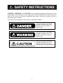


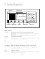

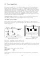
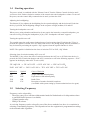
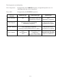

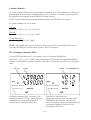

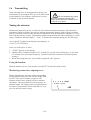

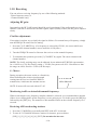
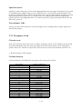


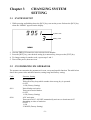

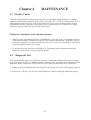
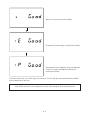


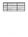
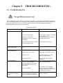


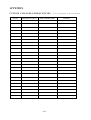
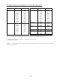
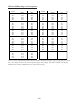
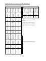
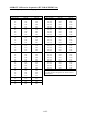
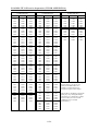
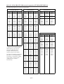

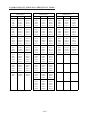
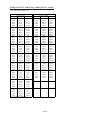
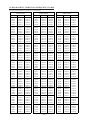
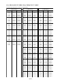
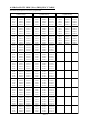


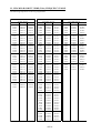


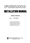
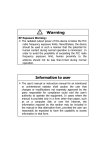
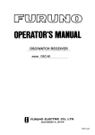
![4403002491_712_716 menu_EN_A [s]](http://vs1.manualzilla.com/store/data/005650300_1-96030b29e24dd373b0bced3bef593dda-150x150.png)