1
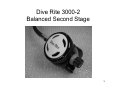
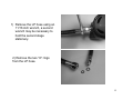
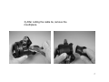
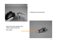
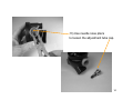
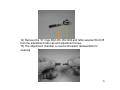
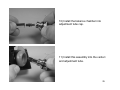
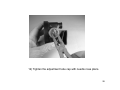
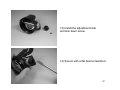
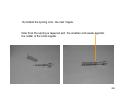
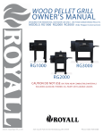
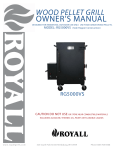
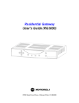
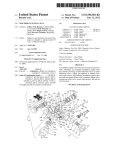
Dive Rite 3000-2 Regulator
Service Manual
Copyright 2007 Lamartek Inc. D/B/A Dive Rite
This manual is intended as a guide for trained and certified Dive Rite regulator technicians. Possession of this guide does not qualify any
individual to service Dive Rite regulator breathing systems. Improper servicing can lead to serious injury or death. Only original Dive Rite
parts are to be used in the servicing of Dive Rite regulators. Any individual who services a Dive Rite regulator without being a certified Dive
Rite technician and is not currently employed by an Active Dive Rite Dealership does so at his own risk. Warranty is void for any regulator
that is serviced by an unqualified individual.
1
Warning
This manual is intended as a guide for trained and
certified Dive Rite regulator technicians. Possession of
this guide does not qualify any individual to service Dive
Rite regulator breathing systems. Improper servicing can
lead to serious injury or death. Only original Dive Rite
parts are to be used in the servicing of Dive Rite
regulators. Any individual who services a Dive Rite
regulator without being a certified Dive Rite technician
and is not currently employed by an Active Dive Rite
Dealership does so at his own risk. Warranty is void for
any regulator that is serviced by an unqualified
individual.
2
Dive Rite 3000-2
Balanced Second Stage
3
Table of Contents
• Schematic…………………..page 5
• Disassembly ………….pages 6-18
• Assembly…………….pages 21-32
4
5
1) Remove the LP hose using an
11/16 inch wrench, a second
wrench may be necessary to
hold the second stage
stationary.
2) Remove the two “O” rings
from the LP hose.
6
3) After cutting the cable tie, remove the
mouthpiece.
7
4) Unscrew the locking ring
and remove the cover and diaphragm.
8
5) Remove the lever arm.
6) Loosen the inlet screw
with an 11/16 inch wrench.
9
7 ) Remove the inlet screw.
Take note of the distance the
orifice extends from the
inlet nipple.
10
8) Use a flat tipped screwdriver to
unscrew the orifice RG1412.
9) It will be necessary to push the
orifice out of the inlet screw.
11
10) Remove the inlet nipple RG1407
and spring.
Note that the spring is tapered.
12
11) Remove the decal on the
adjustment knob.
12) Use a flat tipped screwdriver to loosen
the locking screw.
13
13) Use needle nose pliers
to loosen the adjustment tube cap.
14
14) Remove the “O” rings RG1416, RG1404 and teflon washer RG1415
from the adjustment tube cap and adjustment screw.
15) The adjustment chamber is reverse threaded; disassemble for
cleaning.
15
16) Remove the venturi.
17) Remove “O” ring RG1428SL.
16
18) Remove the adjustment tube.
Note the orientation of the
opening. It faces the deflector in front of the
mouthpiece opening.
17
19) Remove the exhaust tee.
Inspect the exhaust diaphragm
replace if necessary RG1251 (not included in
parts kit).
18
Warning!!! Only original Dive Rite parts are to be used!
• All parts that are removed from the
serviced regulator are to be returned to
Dive Rite under warranty guidelines.
• Remaining parts should be cleaned in a
solution compatible with Nitrox use.
• All points of lubrication should use a Nitrox
compatible lubricant.
19
Assembling the RG3000-2
20
1) Install the exhaust diaphragm.
2) Install the exhaust tee.
It will be necessary to soak the tee in
hot water to make it more pliable, be sure
the tee seats under the body edge.
21
tube opening
deflector
3) Replace “O” ring RG1404.
4) Install the adjustment tube into the
body, the opening on the tube MUST face
the deflector.
22
5) Replace “O” ring RG1428 SL
on the venturi.
6) Install into the body; ensure that
the lever arm on the venturi is
facing the back of the
body.
23
7) Assemble the balance chamber
remember that it is reverse threaded.
8) Replace the “O” ring RG1416
and teflon washer RG1415 on the
adjustment screw.
9) Install the “O” ring RG1404 on the
adjustment tube cap.
24
10) Install the balance chamber into
adjustment tube cap.
11) Install this assembly into the venturi
and adjustment tube.
25
12) Tighten the adjustment tube cap with needle nose pliers.
26
13) Install the adjustment knob
and lock down screw.
14) Secure with a flat head screwdriver.
27
15) Install the orifice RG1412 into
the inlet screw, screw the orifice
down until the conical edge
just meets the edge of the inlet
screw.
28
16) Install the spring onto the inlet nipple.
Note that the spring is tapered and the smaller end seats against
the collar of the inlet nipple.
29
17) Install the spring/inlet nipple assembly
into the adjustment tube.
18) Install orifice/inlet screw.
30
19) Tighten the inlet nipple with
an 11/16 inch wrench.
20) Install the lever arm.
31
21) Install the diaphragm, cover, and locking ring.
The RG3000-2 is now assembled and ready for tuning.
DO NOT INSTALL THE MOUTHPIECE
AND THE DECAL UNTIL AFTER
TUNING THE REGULATOR
COMPLETELY.
32