1
!
man
•MfcdJT
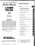
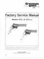
Factory Service Manual
35?
..
Th
ducts. It is not instructional
ttinut proper factory training.
_
AIRGUNS
980 Turk Hi!! Road, Falrport, N.Y. 14450
10/83
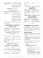
Mode! 357 Service Repair Procedures
Phase I (manufacturing date 8/82}
NOTE,: Safety glasses should be worn when working on all guns.
General operating instructions for this model are contained In the Owners Manual and should be read
thoroughly The detailed drawings, repair instructions and disassembly/assembly procedures must be studied
carefully before any repair work is started. This will insure quicker and more precise repair of gun,
It is not always necessary to disassemble the entire gun in repair work and it is hoped that this section will
assist you in diagnosis of the repair problem and will speed up repair time.
2. Vssve Tube teaher at
Pioteisig Body or Valve
Body (.-.-JUKHiJ by a
defective Quad Seal
(3S7AOS4J.
I - Leaks
i Charge !he gun with new Powerlet pe? instructions ir*
Ing Body may have a s/r.iirh or
ItriHs in it causing Quad Sflai
J357AOS4J lo laak
g, if th« atjove problem sxisit, :t
la rec:;t)iii!n«n<l«d to rep!«C« PiefC-
2. Fire gun making sure Powertat is putting lull charge of CO,
through Vaivc.
3
Pull Hammer buck m single action position and put safety
on to proven* accidental firing,
4, Hold 'BUM!!; <tnd of tjijf 1 down Looking down into Frame.
fifop a. f'JVM drops ot oil down along copper Valve Tube
) : « ; ; li.-.iiv i3S?"A046i or Valw.! Body
3 Dt?t«'ctive Valve Seal
(357-041) or O-ring
n, drop a few i!r.::,[-s ol :.>ii nrough
POSSIBLE CAUSES
1, Detent Spring
f3S7-037) rnisstng or
defective causing little
tension against Cylinder
Detent (357-038)
O«8
t.DSJHiiS
st per in-
.(
(38-128) by rermwmg u We Coiiai
(d
•jcrevudrivpr.
(357-056)
with
wide
Note: !t
not
H- - • -iry tci remove Siae Cover
itiinove End SKH! and replaco.
4, VVHh End Seal romovfjij, in
sped Piwcing Pin (3SA02?) for
damage OF wear and replace at
this time,
6. Wh«tn replacing Guide Collars
(357-058), I»ah1en only slightly
against End Seal Note: Over
tightening *ili cause hard piercIns of PoA-enet
REPAIR PROCEDURES
1.
spring tensirjn against li, If not,
see Group VII Cylinder Piste,
Cylinder Detent and Detent Spring
Group,
2, Improper Installation
or weak Hummer Spring
(357437).
1, Remove Side Covet {357-W2I
writ! sw. G'fjup X! Hammer & Hartifner Spni-g Group and chock il
spring is disiocatea or damaged In
any way.
3. Satety Link (367-033)
not lining up with Valve
Siern properly
1. PuM Hammer back and look
oown Into Frame, Continue to
hold Hammer back and pull Trigger back at same time. Sea it Safety Link is lining up with cense? ot
Valve Stem- If not, sec Group Xil
Trigger, Safely Link S Trigger
Spring Group.
blade
is
1. Sea Disassembly & Assembly
procedures Valve Assy Group X.
II • Low Velocity
; NU? (3S7AMS) on Vaivti Body to
S, Fro
tVif
1 To de1»rmimj what ond ot Valve
Tube is loakrng, read Problem 1
sSeps 1 through S in Troublo
Shootlnfl. Than toliow Group IX
Vatve & Plarcing Body Assy,
disassembly ft. asswrnbly.
/ 'i kKikaqe slii' •.-»'•.':.. .1! ulinji
4. Guide Collar (35/-056I
is too tighi causing par
timl piercing of Powenef,
1. if Guide Collar is over lightened. it will cause EriiJ SI-MI (38-128^
to protrude above Piercing Pin
causing Improper piercing of
Power!at, The Powerlst ahouW be
removed and Guide CoJIaf should
toe baokeoolt a quarter turn.
4. tnded teeth *orn or
broken on Cylir-dor
Assembly
PROBLEM VI! - Hammer Will Not
Lock Back In
Single Action
Ill - Poweriet
Inconsistent C02
SS1BLE CAUSES
1, Defflc'ivo P.nroinq
Pin (3fiA02f|
HEP
POSSIBLE CAUSES
ROCEDURES
1 . NO'lc,: P f e r c l n g Pins have
fttanied iips. If the angle does not
exist, trie cookie cutter acfton of
ihr> Pifi.itiij ' ip will deposil a
srnal! pioi'.s of metal inside
Po'A'irrn'i A'n.ch ftveniually frtay be
forced back plugging the hollo*
tip of piercing pin, Refer to Problem I Leaks.
2, Examine Piercing Ptn (38A02T)
ufldac magnification Replace it
necessary
3. Gui'le Collar is too
!t: Problem M'
CO,
1. *;BMi hi
IV - Gun Shooting
Or Left
To
POSSIBL.L-.CAU5
REPAIR PROCEDURES
1, Refer to Group f Bartel & Barrel
(35?-103) o
Housing,
2. Replace:- BHn«->i <l n
V - Cylinder
To Rotate
POSSIBLE CAUSES
1. ln>
off 01
Ken
Inder
'-052)
I. 'Inuyi i ;-.-*•«• (357 031)
• inp'Operly located Or
Seat Spring (357A029)
missing
REPAIR PROCEDURES
1. Fitter lo Di:,u em&ly ;
Assembly Group VI Tn<;qpr :-,p;r :
Spring Group
PROBLEM VIII - Trigger Fails To
Return Forward Or
Very Little Tension
POSSIBLE CAUSES
«aS7-06r) not located
proparly
REPAIR PROCEDURES
\. Relof to Giou;:
Safesy Link S frigflW '
2 Make sure that !
leg of Trigger Sprinc
located.
DISASSEMBLY AND
Study the drawing carefully as you read
disassembly and assembly procedures and prior
to disassembly of your first gun. Assembly Is in
reverse of disassembly, but special notations
have been made throughout this section to assist
in the assembly procedures.
General Information
1. Exhaust at) CO? Gas and remove PoweHet per
instructions in Owners Manual "To Exfiaust
REPAIR PROCEDURES
1, Open Barrel
Cylinder. Inspoi
necessary.
1. Refer to Group V Levei & Itwt .-
2. Instructions are defmud in assembly groups
and disassembly instructions in each group are
a continuation of the instructions in trie
previous groups,
3, All lubrication should be with Crosman
Peilgunoii as regular gun oil and oil containing
detergents are harmful to the Seals.
VI - Jamming
POS-SI1LE CAUSES
...--
REPAIR PROCEDURES
1, Powerlei low on CO,
t. Remove Barrel and push out
pallets.
2, Weak or damaged
t. Refer to Group XI Hammer &
Hamrn&r Spring Group. Ch«k to
seo if Sf-rn'i'.) is dislocateij ot
damaged in any way.
harni'ii.!('',;•->in:; rss7
llets or
1, Inspect Pellets and advise
ctistofnar, Note: Only Crosirwn
pBltets are i
i
BARREL &
BARREL HOUSING
A. DISASSEMBLY
1, Press the Barrel Latch Button down
and open the barrel,
2, First remove the Pellet Cylinder
(357-017) from Shaft and inspect for
broken ratchet teeth.
3, W i t h Barrel Housing A s s e m b l y
5357-102} or (357-OOi) open, remove
Barrel Housing Screw (357-019) and
remove the complete Barrel Housing
Assembly from main unit.
4. Remove Barrel (357-103) or (357-010)
from Barrel Housing (357-100) or
(357-003) by taking the following steps.
a. Push against muzzle end of Barrel
and carefully slide it out of the
Housing.
b. Lift Barrel Housing Rib (3i7-WS) or
(357-101) out of Barrel Housing.
c. Remove Barrel Latch Plate (357-008),
d. Turn Barrel Housing upside down to
remove Barrel Weight {357-055) or
(357.QS9).
e. Inspect all parts and replace if
necessary,
B, ASSEMBLY
1, Place Barrel Weight back in Barrel
Housing making sure it is properly In
place.
2, Place Barrel Housing Rib Into Barrel
Housing,
3, Slide Barrel Latch Plate (3S7-W8) as
show! 1 cm ilfaw.ru;
4, With srruilt ''in! first, slide Barrel
through Barrel Latch and continue to
slide Barrel into Barrel Housing all the
way,
5, Place complete Barrel Housing
Assembly onto main unit of gun and
replace Barrel Housing Screw (357-019).
6, Replace Cylinder (357-017} over pivot
stud and close Barrel Assembly and at
the same time check to see it If latches properly.
PIN
& SEAL GROUP
A, DISASS
1, it is not necessary to remove any other
part of the gun.
2. Remove the L H. Grip and Powerlel
from gun.
3. With a large blade screw driver,
remove Guide Collar (357-056).
4, With a small pick or screw driver, pull
out
a
5. Tap butt of gun on bench to drop out
Piercing Pin (38AQ27) and Screen
{38-028),
8. ASSEMBLY
1. Turn gun up and drop Screen {18-028)
In Piercing Body.
2. Inspect Piercing Pin (38A027) for any
damage to piercing point before
3. Place End Seal (31-128) on Piercing Pin
(36A027). NOTE: Check for depression
set, chips and for any other defect
before inplacing.
4. Turn Guide Collar (357-056) into Piercing Body), Guide Collar Should be turned down until snug. Beyond this point,
the center of the End Seal (38-128) will
protrude above the Piercing Pin
(3BA027) resulting in partial piercing of
the powerlet.
ill
IV
REAR SIGHT &
SIDE COVER GROUP
A, DISASSEMBLY
1. Note; The Rear Sight can not be
removed until the side cover is removed.
2. Remove the two (2) Frame Screws
138-117) and one (1} Barrel Housing
Screw (387-019).
3. Before removing Side Cover (357-QG2),
push safety in by pulling Hammer back
slightly. Then carefully lift off Side
Cover (357-002).
4. Lift out Been Sight Assembly (357-012)
and inspect before replacing,
5. If Elevation Screw (357-011) needs
replacing, turn out from bottom of
Sight.
B. ASSEMBLY
1. With Elevation Screw turned in from
bottom of Rear Sight so that it will
clear Valve Body.
2, Carefully place Rear Sight Assembly
down In casting properly.
3. If Side Cover does not go down
against main casting properly, check
for mislocated parts like Trigger Pin,
Sear Pin, Piercing Body and Safety.
4, Make sure all parts are properly
d then
id Cover
(357-002) and replace the screws.
BARREL HOUSING
LATCH GROUP
A, DISASSEMBLY
1, Remove Side Cover as instructed above.
2. Carefully remove Latch Support
(357-021).
3. Lift out Barrel Housing Latch (3S7-020),
4, Inspect parts for damage and wear
and replace if necessary.
B. ASSEMBLY
1. Locate Pivot Pin on Barrel Housing
Latch in hole in casting and with hook
of latch up.
2. Place Latch Support (357-021) on top Of
Cylinder Plate (357-035) and with
tapersd end under Barrel Housing
Latch (357-020). Note: Make sure
Latch Support is located properly
against Cylinder Plate (3S7-03S) and
casting flange,
3. Replace Side Cover (3S7-002) as
instructed,
4, Now Place the two Quad Seals on
each end ol the Valve Tube (357-044).
5, With the two Quad Ring Retainers and
Quad Seals assembled on each end of
the Valve Tube, as one unit, press one
end in Piercing Body and one end in
Valve Body as far as they will go, Note:
Quad Seals must be assembled on
Valve Tube and then pressed into
Valve and Piercing Body. If this is not
done properly, the Quad Seal will not
seal themselves around Valve Tube,
6, By holding Valve & Piercing Assembly
together as one unit, piace in Frame as
stated in '-7 below,
7, With Hani (Tier Spring (357-027) located
on stud and under Hammer as shown
on drawing, press Piercing Body
Assembly against short end of Hammer Spring and into Frame Make sure
that rib in Frame is between Piercing
Body 6, Guide Collars. Then continue
to hold Valve Body Assembly against
Valve Tube and place Valve Assembly
in Frame making sure small tab on
Valve Body is located in locating slot
in Frame,
VALVE ASSEMBLY
A. DISASSEMBLY
1, With Valvi Body Assembly (357B049)
removed from Frame, proceed to
disassemble Valve Assembly as
2, Using wrench T3S-11 furnished by
Crosman, turn out Valve Seal Retainer
Nu! (357A043J,
3, Remove Valve
(357-0411, Valve
Stem (357-039) and Valve Spring
(111A026).
4, By using a pick or tiook tool, put! out
Valve Washer (357-040) and G-ring
(38-130)
5, All parts, seals arid O-rmgs should be
inspected for chips, dents and tor any
other defects. It Is recommended that
Valve Seal (357-Q41J and 0-ring {38-130}
be replaced while the Valve is
fio a^-.-'..• mi. o:d,
B. ASSEMBLY
1, Place O-ring {38-130) into Valve Body
(357AG38) In recessed area.
2, Drop in Valve Washer {357-040} and
press down on washer to make sure
0-ring (31*130) is properly seated,
3, Drop Valve Spring (111A026) in Valve
Body,
4, Piace Valve Stem (35F-03S) on Valve
Spring.
5. Place Valve Seal (357-041) and Valve
Seal Retainer Nut (357A043) over Valve
Stem (357-03i) and turn Valve Seal Retainer Nut with wrench until tight,
XI
HAMMER &
HAMMER SPRING GROUP
A. DISASSEMBLY
1. Pull out floating Pivot Pln{3S-012)from
Hammer Assembly (3S7-Q3Q) and
locating hole In Frame.
2. Lift out Hammer Assembly (357-030)
and inspect for damage1 or \<vear.
Note: Hammer Paw! (3SF-028) and
Pawl Spring (357-042) should work freely and should be inspected for that,
3. Remove Hammer Spring (357-027) from
stud in Frame and should be inspected.
B. ASSEMBLY
1. Place Pfvot Pin (36-Q12} in locating
hole in casting,
2. Place Hammer Assembly (357-030)
over Pivot Pin (36-012),
3. Place Hammer Spring (357-027) over
stud in frame with long end of spring
so it win press against Hammer,
Xli
TRIGGER, SAFETY LINK &
TRIGGER
GROUP
A, DISASSEMBLY
1. It Is helpful to study how and where
Trigger Spring (357-057) is located in
Frame,
2. Unhook Trigger Spring (357-Q57) from
boss to release tension.
3. Pull out Pivot Pin (36-012) from Trigger
(357-032) and Frame,
4. Remove Trigger (357-032), Trigger
Spring (357-057) and Safety Link
(357-033),
5. Inspect all above parts for damage or
B, ASSEMBLY
1. Place Pivot Pin (36-012} in locating
hole in Trigger area of Frame-,
2. Place Trigger Spring (357-057) over
Pivot Pin and locate long straight end
of spring between Trigger Guard and
Boss Flange so that Spring will be
relaxed while replacing Trigger.
3. Put short end of Safety Link (357-033)
In hole in Trigger from right side and
hold Safety Link and Trigger together
as one unit. Place over Pivot Pin allowing hook part of Trigger Spring to rest
against flat straight part of Trigger.
Note: At this point, there should not
be any tension against Trigger, (read
next step)
4, Hold Trigger Assembly down and take
long straight end of Trigger Spring and
hook it on top of boss flange.
Note: This will give you the proper tension on Trigger,
Kill PIERCING LEVER PIN,
LEVER AND
GROUP
A. DISASSEMBLY
1, Note; The only time this Group is
disassembled is when Piercing Screw
(357-015) is broke off or damaged.
2, To remove Piercing Screw when
broken at Piercing Lever take the
following steps:
a. Grind the end of screw so that all
burrs or damaged threads are
removed. If this is not done, you will
damage the thread;,! in the Frame
{357-016}.
b. Turn Piercing Screw out up through
p O W O l l O l itH.<,•••:.->':,ril OpBflir'liJ by u5intj
a small pair of pliers or alien wrench
size %„, If there Is difficulty in turning Piercing Screw out, double
check to see If threads on screw are
damaged, Note: A noticeable tightness will be felt when Piercing
Screw is being turned out,
B. ASSEMBLY
1, Turn Piercing Screw 1357-015) back
through Frame (357-018)
2, Assemble Piercing Lever (357-014),
Piercing Lever Pin (357-013) to Piercing
Screw (357*015).
3, Place head of Lever Pin on block and
pean end over,