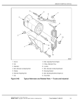
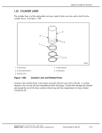
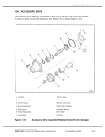
1
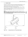
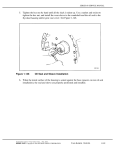
SERIES 60 SERVICE MANUAL
before tightening the bolts. This will help eliminate the potential for any interference
between the flywheel housing and the oil pan.
1. Drain Plug
6. Bolt
2. Nut
7. Plug
3. Isolator Seal
8. Insert
4. Sleeve
9. Seal
10. Bolt ASM, Replaces 4, 5, 6
5. Isolator and Washer
Figure 3-38
Typical Oil Pan Assembly
All information subject to change without notice.
(Rev. 2006)
6SE483 0507 Copyright © 2005 DETROIT DIESEL CORPORATION
From Bulletin 3–60–06
3-75
3.1
OIL PAN
The plastic oil pan has side plugs that are threaded into a special stainless steel insert which is
restrained by a nut inside the pan. Sealing is provided by a fluoroelastomer seal ring that fits into a
groove machined on the flange of the insert. See Figure 3-39.
1. Plug
4. Nut
2. Insert
5. Oil Pan
3. Seal
Figure 3-39
Side Plug Detail
Rubber isolator-washer assemblies and sleeves are used for attaching the oil pan. The metal
sleeve spacer is inserted through the isolator and limits the travel of the oil pan bolts to prevent
over-tightening and damaging the oil pan and isolator.
Effective August 1995, isolators made of an improved vibration-absorbing material were released
to reduce noise emissions. In addition, isolator bolt sleeve length was increased by 0.8 mm (0.032
in.) to accommodate the slightly longer isolators.
When installing a pipe plug, coat the threads with Loctite® PT 7271 sealant (or equivalent), hold
the insert to keep it from turning, and torque the plug to 45-56 N·m (33-41 lb·ft).
Effective November 2005, an oil pan adaptor service kit became available for the 12.7L and 14L
engines to increase oil capacity for approved engine applications. The oil pan adaptor is only
available for the vinyl rear sump, vinyl front sump, and aluminum low profile rear sump oil pans.
NOTE:
Customers who want to add an oil pan adaptor service kit should refer to publication
18SP626 or contact the Detroit Diesel Customer Support Center at 313-592-5800 with
their engine data to see if the service kit is compatible with the engine.
(Rev. 2006)
3-76
From Bulletin 3–60–06
All information subject to change without notice.
6SE483 0507 Copyright © 2005 DETROIT DIESEL CORPORATION
SERIES 60 SERVICE MANUAL
3.1.1
Repair or Replacement of Oil Pan
To determine if repair is possible or replacement is necessary, perform the following procedure.
See Figure 3-40.
Figure 3-40
Flow Chart for Repair or Replacement of Oil Pan
All information subject to change without notice.
(Rev. 2006)
6SE483 0507 Copyright © 2005 DETROIT DIESEL CORPORATION
From Bulletin 3–60–06
3-77
3.1
OIL PAN
3.1.2
Removal of Oil Pan
Precleaning is not necessary.
NOTICE:
Do not support the engine on the oil pan. Damage to the oil pan
or engine could result.
NOTE:
On almost all engine applications it is possible to remove the oil pan without removing
the engine.
If the engine is to be removed from the vehicle, the oil pan should be left in place until the engine
is removed.
The procedure for removing the oil pan will vary with each installation. However, the following
procedures will generally apply.
NOTICE:
When removing a side plug, hold the flats of the insert with a
2-1/8 in. open end or large adjustable wrench to keep it from
turning. If the insert is loosened, it may be necessary to remove
the oil pan and tighten the nut to prevent a possible oil leak. If
required, torque the nut to 186-199 N·m (137-147 lb·ft).
Remove the oil pan as follows:
1. Remove the drain plug and drain the engine oil.
2. Remove the ten oil pan bolts, washers, isolators and sleeves or ten bolt assemblies.
Remove the counter bolts on each side last.
3. Remove the oil pan, taking care not to damage the oil pump inlet pipe and screen.
4. Remove the oil pan isolator seal and inspect for damage.
5. If the engine application uses an oil pan adaptor service kit, remove the ten oil pan
extender bolts and oil pan adaptor.
3.1.3
Cleaning of Oil Pan
Clean the oil pan prior to inspection as follows:
1. Clean the oil pan and attaching hardware with clean fuel oil.
(Rev. 2006)
3-78
From Bulletin 3–60–06
All information subject to change without notice.
6SE483 0507 Copyright © 2005 DETROIT DIESEL CORPORATION
SERIES 60 SERVICE MANUAL
EYE INJURY
To avoid injury from flying debris when using compressed
air, wear adequate eye protection (face shield or safety
goggles) and do not exceed 276 kPa (40 psi) air pressure.
2. Dry with compressed air.
NOTICE:
Do not use solvents to clean isolators. Damage to the isolator
will result.
3. Clean the surfaces of the cylinder block, gear case and flywheel housing where they mate
with the oil pan. Use LPS, Permatex, or an equivalent non-filming degreaser.
3.1.3.1
Inspection of Oil Pan
Inspect the oil pan, inserts, bolt isolators and isolator seal as follows:
1. Check the isolators for dryness, cracks or tears.
[a]
If isolator is damaged, replace with new part.
[b]
If isolator is not damaged, reuse the part.
2. Check oil pan inserts and nut assemblies for tightness.
[a]
If inserts and nut assemblies are loose, torque to 183-197 N·m (135-145 lb·ft).
3. Check oil pan for major dents, cracks and other damage.
[a]
If oil pan is damaged, replace with new part.
[b]
If oil pan is not damaged, reuse the part.
4. Check isolator seal for dryness, cracks or tears.
[a]
If seal is damaged replace with new part.
[b]
If seal is not damaged clean off excess RTV clean seal with clean fuel oil dry
completely and reuse part.
5. If the oil pan has an oil pan adaptor service kit, check the adaptor for flatness, dents,
cracks, and other damage.
[a]
If oil pan adaptor is damaged, replace with a new part.
[b]
If oil pan adaptor is not damaged, reuse the part.
All information subject to change without notice.
(Rev. 2006)
6SE483 0507 Copyright © 2005 DETROIT DIESEL CORPORATION
From Bulletin 3–60–06
3-79
3.1
OIL PAN
3.1.4
Installation of Oil Pan
Install the oil pan as follows:
1. Insert the raised lip portion of the isolator seal into the groove in the oil pan.
2. Press down on the isolator seal and insert it completely around the oil pan. Be careful
not to stretch or bunch the seal. For best results, install the seal at each corner, then at
points half way between the corners. Continue in this manner, halving the distance and
seating the seal.
3. Insert a metal sleeve spacer into each isolator and washer.
4. Install the ten oil pan bolts into isolator assemblies or install ten bolt assemblies.
5. Ensure the joint surfaces of the gear case and the cylinder block, the gear case cover and
gear case, and the flywheel housing and the cylinder block are cleaned and there is no
damage to prevent sealing.
6. Apply a 3 mm (1/8 in.) bead of RTV across joints shown. See Figure 3-41.
Figure 3-41
RTV Application
7. If the engine application uses an oil pan adaptor service kit, install the oil pan adaptor
as follows:
[a]
Position the oil adaptor under the cylinder block and secure with several of the oil
pan extender bolts. Ensure that the adaptor does not interfere with the flywheel
housing. If there is interference, use a beveled adaptor to maintain clearance.
(Rev. 2006)
3-80
From Bulletin 3–60–06
All information subject to change without notice.
6SE483 0507 Copyright © 2005 DETROIT DIESEL CORPORATION
SERIES 60 SERVICE MANUAL
[b]
Remove the adaptor and place it on a flat table or the floor. Apply a 3 mm (1/8 in.)
high bead of sealant 23525918 (50mL) or 23525919 (330mL) in the adaptor
groove. See Figure 3-41a.
Figure 3-41a
Oil Pan Adaptor and Tightening Sequence
[c]
Place the adaptor in position on the cylinder block.
[d]
Install and slightly tighten the ten extender bolts.
[e]
Tighten the extender bolts to 24-30 N·m (18-22 lb·ft). See Figure 3-41a for the
torque sequence.
8. Install the oil pan assembly in position on the cylinder block or oil pan adaptor.
9. Ensure that the isolator seal has not been disturbed. Torque the ten oil pan bolt assemblies
to 24-30 N·m (18-22 lb·ft), using the proper sequence. See Figure 3-42.
Figure 3-42
Oil Pan Bolt Sequence
10. Install and torque the 3/4 in.-14 square, magnetic, oil drain plug to 45-56 N·m (33-41 lb·ft).
All information subject to change without notice.
(Rev. 2006)
6SE483 0507 Copyright © 2005 DETROIT DIESEL CORPORATION
From Bulletin 3–60–06
3-80a
3.1
OIL PAN
11. Install and tighten any other plugs that were removed from the oil pan.
NOTE:
When installing a pipe plug, coat the threads with Loctite® PT 7271 sealant (or
equivalent).
12. Refill the crankcase with lubricating oil. Refer to section 14.6.1.
13. Refer to section 12.3 for verification of proper oil pan installation.
(Rev. 2006)
3-80b
From Bulletin 3–60–06
All information subject to change without notice.
6SE483 0507 Copyright © 2005 DETROIT DIESEL CORPORATION
SERIES 60 SERVICE MANUAL
This page intentionally left blank.
All information subject to change without notice.
(Rev. 2006)
6SE483 0507 Copyright © 2005 DETROIT DIESEL CORPORATION
From Bulletin 3–60–06
3-81
3.12
VENTILATING SYSTEM
3.12 VENTILATING SYSTEM
Vapors, formed within the engine, are removed from the crankcase, gear train and valve
compartment by a continuous pressurized ventilating system.
A slight pressure is maintained in the engine crankcase by the normal seepage of a small amount
of air and combustion gases past the piston rings. These gases are swept up through the engine and
pass through a crankcase breather. On vehicle engines the gases are then vented to the atmosphere.
Breather extension hoses may be required on certain Series 60 engines used in on-highway
vehicle applications. Under certain conditions, the vapors from an operating engine may be
circulated through the battery charging alternator by the alternator cooling fan. Excessive
ingestion of vapors may lead to alternator malfunction. This can occur if the internal components
of the alternator become coated with oil-laden dust or road grit.
To minimize the potential for this condition, check the length of the engine breather tube and add
an extension hose, if necessary. For proper dissipation of vapors, the end of the breather hose
must extend at least 12 inches below the oil pan rail.
A wire mesh element is located inside the valve cover, or in a separate housing on the valve cover
cap or at the gear case cover. This element traps excess engine oil particles in the vapor and
returns them to the crankcase. See Figure 3-43.
NOTE:
The Series 60G automotive engine uses a closed crankcase breather system.
Refer to section 6.4 for more information.
(Rev. 2006)
3-82
From Bulletin 3–60–06
All information subject to change without notice.
6SE483 0507 Copyright © 2005 DETROIT DIESEL CORPORATION