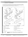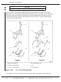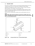
1
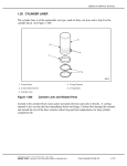
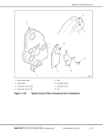
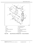
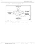
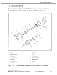
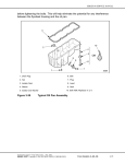
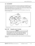
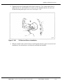
SERIES 60 SERVICE MANUAL
5. Tighten the hex nut by hand until all the slack is taken up. Use a ratchet and socket to
tighten the hex nut, and install the wear sleeve to the crankshaft and the oil seal to the
flywheel housing and/or gear case cover. See Figure 1-148.
Figure 1-148
Oil Seal and Sleeve Installation
6. When the inside surface of the housing is seated against the base (spacers on rear oil seal
installation), the seal and sleeve are properly positioned and installed.
All information subject to change without notice.
(Rev. 2004)
6SE483 0401 Copyright © 2004 DETROIT DIESEL CORPORATION
From Bulletin 13-60-04
1-189
1.9
1.9
CRANKSHAFT MAIN BEARINGS
CRANKSHAFT MAIN BEARINGS
The crankshaft main bearing shells are precision made and are replaceable without machining.
They consist of an upper bearing shell seated in each cylinder block main bearing support and a
lower bearing shell seated in each main bearing cap. See Figure 1-149.
1. Upper No. 6 Thrust Washers
8. Main Cap No. 1, 2, 3, 4, 5 & 7
2. Crankshaft
9. Lower Thrust Bearing Shell
3. Lower No. 6 Thrust Washers
10. Woodruff Key
4. Lower No. 6 Thrust Bearing Shell
11. Upper Thrust Bearing Shell No. 1, 2, 3, 4, 5 & 7
5. Washer
12. Cylinder Block
6. Bolt
13. Upper No. 6 Thrust Bearing Shell
7. No. 6 Main Cap
Figure 1-149
Main Bearing Caps, Bearing Shells and Crankshaft Thrust
Washers
(Rev. 2004)
1-190
From Bulletin 13-60-04
All information subject to change without notice.
6SE483 0401 Copyright © 2004 DETROIT DIESEL CORPORATION
SERIES 60 SERVICE MANUAL
The upper and lower bearing shells are located in the respective block and bearing cap by a
tang. The tang is located at the parting line at one end of each bearing shell. The tangs are
offset from center to aid correct insertion. Bearing shell sets are supplied as a matched assembly
and should not be mixed.
A hole in each upper bearing shell registers with a vertical oil passage in the cylinder block.
Lubricating oil, under pressure, passes from the cylinder block oil gallery by way of the bearing
shells to the drilled passage in the crankshaft, then to the connecting rods and connecting rod
bearings. The upper bearing shell is also grooved.
The lower main bearing shells have no oil holes or grooves. Therefore, the upper and lower
main bearing shells must not be interchanged.
Thrust washers on each side of the No. 6 main bearing absorb the crankshaft thrust. Engines built
prior to 06R0762048 use the two-piece washers with locking tangs that register with locating
notches in the bearing shell. See Figure 1-149.
All information subject to change without notice.
(Rev. 2004)
6SE483 0401 Copyright © 2004 DETROIT DIESEL CORPORATION
From Bulletin 13-60-04
1-191
1.9
CRANKSHAFT MAIN BEARINGS
NOTICE:
Do not mix old and new style thrust washers in the same engine.
Engines built after serial number 06R0762048 will accommodate the current style four-piece
thrust washer as well as the former style two thrust washer version. See Figure 1-149. The current
style thrust washers are marked for front and rear and are designed to directionally rotate into
the same upper position with the main bearing cap removed. The No. 6 position main bearings
are the same as the other postion.
1. Upper Thrust Washer (2)
4. No. 6 Main Bearing Cap
2. Upper No. 6 Bearing Shell
5. Bolt
3. Lower No. 6 Bearing Shell
6. Thrust Washer (2)
Figure 1-149
No. 6 Thrust Bearing Detail
The condition of the lower bearing shells may be observed by removing the main bearing caps.
(Rev. 2004)
1-192
From Bulletin 13-60-04
All information subject to change without notice.
6SE483 0401 Copyright © 2004 DETROIT DIESEL CORPORATION