1
-J04929
REV. 2010-04-20
BOOM! AUDIO MUSIC AND INTERCOM KIT
GENERAL
INSTALLATION
Kit Number
Install Switch Housing on Passenger Headset
Harness
77107-09
Models
For model fitment information, see the P&A retail catalog or
the Parts and Accessories section of www.harley-davidson.com
(English only).
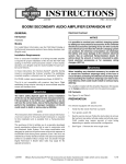
1.
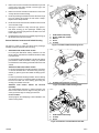
See Figure 1. Install push-to-talk switch housing (2) to
passenger headset plug housing (3), included as part of
communication switch wire harness (see Figure 7, Item
10).
2.
Position the switch housing so the knob is located close
to the flip cap on the passenger headset connector.
3.
Install self-tapping screws (1) to the switch housing but
do not fully tighten at this time. Location adjustment may
be required based on the motorcycle model, seats and
accessories installed on the vehicle.
Additional Parts Required
Intercom system flash (H-D Part No. 76441-06DT)
NOTE
For a more integrated appearance of the rider headset connector, the console may be replaced using an Ultra Classic
Electra Glide console and/or console pod. See FLHTCU parts
manual for applicable parts, and service manual for installation
instructions.
2
is06089
2
The rider's safety depends upon the correct installation
of this kit. Use the appropriate service manual procedures.
If the procedure is not within your capabilities or you do
not have the correct tools, have a Harley-Davidson dealer
perform the installation. Improper installation of this kit
could result in death or serious injury. (00333a)
3
NOTE
1
This instruction sheet refers to service manual information. A
service manual for this year/model motorcycle is required for
this installation and is available from a Harley-Davidson dealer.
1. Self-tapping screws
2. Push-to-talk switch housing
3. Passenger headset plug housing
Kit Contents
Figure 1. Install Push-to-Talk Switch Housing
See Figure 7 and Table 1.
REMOVAL
1.
Refer to the service manual and remove the following:
a.
Main fuse.
b.
Outer fairing.
c.
Seat.
d.
Fuel tank and console.
e.
Inner fairing cap.
f.
Wire trough cover.
g.
Left hand control.
h.
Left side saddlebag.
-J04929
Install Push-to-Talk/Audio Left-Hand Control and
Speaker Selection Switch
1.
Refer to the service manual to install the Push-toTalk/Audio left hand control and speaker selector switch
and adapter wire.
NOTE
Reuse the original clutch switch if the vehicle is equipped with
a hydraulic clutch master cylinder.
Route Overlay Harness
1.
Remove the P-clamp fastener that secures the wire harness on the left side of the frame near the steering head.
2.
Connect the 35-way radio connector [28] to the back of
the radio.
Many Harley-Davidson® Parts & Accessories are made of plastics and metals which can be recycled.
Please dispose of materials responsibly.
1 of 5
3.
Refer to the service manual for this model motorcycle and
connect the 6-way audio harness connector [6] to the
fairing harness connector.
4.
Refer to the service manual for instructions to secure the
overlay harness inside the fairing.
5.
Route the passenger headset end of the harness through
the inner fairing and through the left frame P-clamp.
Replace the P-clamp fastener.
6.
Route the harness down the frame backbone to the inside
of the harness trough.
7.
See Figure 1. Route the 6-way connector [41], push-totalk switch housing (2) and passenger headset plug
housing (3) connector [76] down the left side to the rear
fender support cover.
8.
Double back the harness so the headset plug housing (3)
flip-lid faces the front of the vehicle.
Secure Headset Connector and Switch Housing
NOTE
See Figure 7. Install a P-clamp from the kit to the passenger
headset connector behind the switch housing.
1.
2006-2008 FLHX, FLTR, FLHT/C models:
is06095
5
1
2
3
4
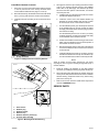
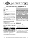
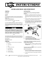
1.
2.
3.
4.
5.
Headset/Switch Assembly
Spacer (2009-later models)
Washer
Screw
P-clamp
Figure 2. Installation Without Docking Points
is06097
1
For motorcycles WITHOUT docking hardware, use the
fender support cover fastener to install the smaller P-clamp
(15) from the kit.
For vehicles WITH docking hardware, use the front docking
point fastener. Install the smaller P-clamp (15) between
the outside face of the docking point behind the screw and
washer.
2009-later FLHX, FLTR, FLHT/C models:
For motorcycles WITHOUT docking hardware, see Figure
2. Use the threaded hole in the frame using screw (4),
washer (3), spacer (2) and the smaller P-clamp (5) from
the kit.
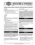
For motorcycles WITH docking hardware, use the docking
point shown in Figure 3. Install the smaller P-clamp from
the kit to the outer end of the docking point using the
docking point washer and screw.
2009-later Trike
(FLHXXX):
models
without
1. P-clamp (wiring harness not shown)
the Tour-Pak
The headset/switch assembly (1) will be secured to the
frame at the location shown in Figure 4 using the 1/2-13
screw (3) and the larger P-clamp (2) from the kit.
Figure 3. Installation With Docking Points
is06154
For ALL models:
Securely tighten the self-tapping screws installed to the
switch housing earlier.
1
2
3
1. Headset/Switch Assembly
2. P-clamp
3. Screw
Figure 4. Installation on Trikes Without Tour-Pak
-J04929
2 of 5
4.
Install Rider Headset Connector
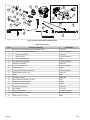
See Figure 6. Clean the clip mounting area with a mixture
of 50 to 70% isopropyl alcohol and 30 to 50% distilled
water. Allow to dry thoroughly. The adhesive clip will be
secured to the lower portion of the fuel tank, so it will be
covered by the seat.
1.
See Figure 5. Connect the rider headset harness (Figure
7, item 11) from the kit to the 12-way connector of the
communication switch harness (Figure 7, item 10).
2.
Route the harness up the left side of the frame tube about
6.0 in (15.2 cm) past the lower console mount fastener.
a.
Install the clip (4) on the wire harness. Do not remove
the adhesive backer at this time.
3.
Install the fuel tank according to service manual instructions.
b.
Install the narrow end of the headset bracket (3)
between the console molding strip and the console
at the lower left corner of the console as shown.
c.
Trim the adhesive patch (5) to the shape of the back
of the headset plug (2), remove one side of backer
and apply to the back of the connector plug to protect
the tank from scuffing.
is06099
1
Trim the adhesive patch to a 0.5 x 0.25 in (12 x 6 mm)
rectangle. Remove one side of the backer and apply
to the underside of the bracket as shown.
1. 12-way connector
Figure 5. 12-Way Connector of Overlay Harness
Position the headset connector facing up and use the
wider end of the bracket to secure the flat portion of
the headset connector as shown.
e.
Remove the backer from the other side of the patches
to secure the bracket to the connector and connector
to the fuel tank.
f.
Install the adhesive back clip (4) as shown. Remove
the adhesive backer from the clip and install the clip
onto the fuel tank where it will be covered by the seat.
NOTE
Allow AT LEAST 24 hours after applying the clip before
exposing the area to vigorous washing, strong water spray or
extreme weather.
is06148a
1
3
d.
5.
Install the weather cap assembly on the rider headset
connector by installing the locking ring inside the flip cap.
6.
Secure all wiring with cable straps as needed. Check the
motorcycle to verify that the wire harness does not interfere
with the steering, suspension travel or any other moving
parts of the motorcycle.
7.
Refer to the service manual to install all the components
removed in REMOVAL Step 1.
4
2
SERVICE PARTS
1
2
3
5
1.
2.
3.
4.
5.
6.
6
Tank console
Headset plug
Headset bracket
Adhesive clip
Headset adhesive patches (2)
Console rubber molding
Figure 6. Mounting Rider Headset Plug
-J04929
3 of 5
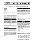
is06109a
17
6
4
12
15
13
14
16
21
5
7
3
8
19
2
18
20
1
9
10
11
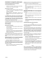
Figure 7. Service Parts, Music and Intercom Kit
Table 1. Service Parts
Item
Description (Quantity)
Part Number
1
Switch and housing subassembly (includes Items 2-5)
77133-09
2
•
Switch assembly (includes Item 3)
Not sold separately
3
•
Knob, PTT VOL-/VOL+
71814-98
4
•
Switch housing
Not sold separately
5
•
Screw, self-tapping (2)
3152
6
Left hand control, PTT/Audio
Not sold separately
7
Weather cap assembly
76266-98
8
Clip, nylon, self adhesive
Not sold separately
9
Cable strap (10)
10006
10
Communication switch wire harness
Not sold separately
11
Rider headset harness, 7 pin
77121-08
12
Spacer
5689
13
Flat washer (chrome)
(TORX®),
94066-90T
14
Button head screw
15
Cushioned P-clamp (smaller)
9990W
16
Cushioned P-clamp (larger)
10036
17
Speaker selector switch
77092-98
18
Wire adapter
77174-06
19
Rider headset bracket
Not sold separately
20
Adhesive patch, 1.5 x 1.0 inch
Not sold separately
21
Screw, 1/2-13 x 0.75 inch
868A
-J04929
5/16-18
4334
4 of 5
FEATURES OF ADVANCED AUDIO RADIO
Understanding Speaker/Volume Features
Intercom volume can be found by pressing the INT button on
the radio face. It can only be adjusted in INT mode.
•
Volume can be adjusted by rider OR passenger independently.
•
Note "F" for front/rider and "R" for rear/passenger volume
settings displayed on screen .
•
Press the INT button again to return to normal music
operation.
A three-position speaker switch is:
•
Standard on FLHTCU, FLHTCUTG and FLHTK models.
•
Included in kits 77107-09 and 77108-09A.
Basic points to remember:
•
The speaker switch controls the location through which
music and bike-to-bike communications are heard
(speakers or headsets).
•
Rider-to-passenger communications ("Intercom") are
ALWAYS heard through the headsets, regardless of switch
position.
In the down position (nearest rider), audio and bike-to-bike
communication will be heard through the vehicles speakers.
Intercom will come through the rider and passenger headsets.
In the middle position, audio will be heard through the vehicle
speakers. Bike-to-bike communication and intercom will come
through the rider and passenger headsets.
In the up position (furthest from the rider), audio, bike-to-bike
communication and intercom will come through the rider and
passenger headsets.
Bike-to-bike communication volume can be found by pressing
the COM button on the radio face. It can only be adjusted in
COM mode.
•
Volume can be adjusted by rider OR passenger independently.
•
Note "F" for front/rider and "R" for rear/passenger volume
settings displayed on screen.
•
Press the COM button again to return to normal music
operation.
•
The rider or passenger can press the PTT button to communicate with other motorcycles or vehicles equipped with
a CB system.
Understanding Intercom Voice Activation
NOTE
Volume Settings
Basic points to remember:
•
There are separate volume settings for speaker and front
and rear headsets.
•
There are separate volume settings for music, intercom,
and bike-to-bike (CB).
•
Getting these volume settings out of proper adjustment is
likely the second-most confusing/frustrating aspect a
customer could encounter.
Volume settings for audio, communication, and intercom are
all independent and all adjusted by using the AUDIO +/- switch
on the rider left hand control or passenger PTT/VOL+/VOLswitch.
Audio (music) speaker volume can be adjusted by the RIDER
ONLY while listening to music via speakers by pressing up or
down on the audio button on the left hand control.
•
VOX, Voice Operated eXchange, (a.k.a. "Voice Activation") is
used to open and close the microphone when rider and passenger are using intercom to talk to each other while riding.
When the microphone is "open", the music being played is
muted slightly to become "background music" during conversation. Once the microphone closes, music volume returns to
its previous setting.
This VOX sensitivity setting can be adjusted by pressing the
intercom button on the radio face and utilizing the Mode +/switch on the right hand control.
•
Turning the sensitivity down will require the rider and
passenger to speak louder to start a conversation.
•
Turning the sensitivity up will open the microphone more
easily, with lesser voice strength needed.
•
As road conditions change, highway vs. city streets, or as
the wind changes, adjustments to VOX will likely be
required, since the background noise is added to the
spoken voice level to "break" the VOX setting and open
the microphone.
Note that a "Speaker" icon displays on screen.
Audio (music) headset volume can be adjusted by rider OR
passenger independently while listening to music by pressing
up or down on the audio button on the left hand control or
passenger PTT switch.
•
This feature works with few problems when set up properly,
but an be the biggest source of confusion and frustration for
an inexperienced user.
Note "F" for front/rider and "R" for rear/passenger settings
display on screen in headset mode.
NOTE
Music is muted (whether in speakers or headsets) whenever
the VOX is opened for intercom use. Unexplained, intermittent
music volume can often be due to VOX setting being set too
sensitively for the current conditions, causing the microphone
to open and "mute" the music intermittently.
-J04929
5 of 5