1
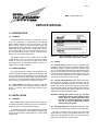
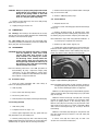
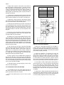
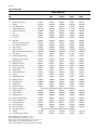
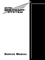
S ERVICE M ANUAL
TABLE OF CONTENTS
Page
1-1. INTRODUCTION ............................................................1
1-2. GENERAL ..............................................................1
1-3. NAMEPLATE DATA................................................1
1-4. Pump Rotation ...............................................1
2-1. INSTALLATION..............................................................1
2-2. GENERAL ..............................................................1
2-3. PIPING ...................................................................1
2-4. Suction Piping ...............................................1
2-5. Suction Housing Rotation ..............................1
2-6. Discharge Piping ...........................................1
2-7. FOUNDATION........................................................2
2-8. SHAFT ALIGNMENT..............................................2
2-9. On Coupling Connected Units ......................2
2-10. On Belt Drive Units .....................................2
2-11. PACKING LUBRICATION.....................................2
3-1. OPERATION ..................................................................2
3-2. INITIAL CHECK......................................................2
3-3. START-UP..............................................................2
3-4. PACKING LEAKAGE .............................................3
4-1. MAINTENANCE .............................................................3
4-2. GENERAL ..............................................................3
4-3. PACKING ADJUSTMENT ......................................3
4-4. PACKING REPLACEMENT ...................................3
4-5. LUBRICATION ...................................................... 4
4-6. Bearings ........................................................ 4
4-7. Gear Joints.................................................... 4
4-8. DISASSEMBLY ..................................................... 4
4-9. Disconnect Pump........................................ 4
4-10. Packing Removal ................................................ 4
4-11. Stator Removal ........................................... 4
4-12. Drive End Gear Joint Removal ....................5
4-13. Rotor and Connecting Rod Removal ...........5
4-14. Drive Shaft and Bearings Removal..............5
Page
4-15. CLEANING .................................................................. 5
4-16. INSPECTION ...............................................................5
4-17. Bearings ..............................................................5
4-18. Drive Shaft .........................................................5
4-19. Seals ...................................................................5
4-20. Packing ...............................................................5
4-21. Rotor ...................................................................5
4-22. Stator...................................................................5
4-23. All Other Parts ....................................................5
4-24. ASSEMBLY ..................................................................6
4-25. Lubrication During Assembly ..............................6
4-26. Packing Installation .............................................6
4-27. Bearing Housing/Suction
Housing Assembly...............................................6
4-28. Bearing/Drive Shaft Assembly ............................6
4-29. Rotor/Stator Assembly ........................................7
4-30. Rotor Gear Joint Assembly .................................7
4-31. Rotor/Stator to Drive End Assembly ...................8
4-32. Drive End Gear Joint Assembly .........................9
4-33. Stator Support/Discharge Assembly ...................9
4-34. Final Assembly ...................................................9
4-35. Packing Adjustment ...........................................9
4-36. STORAGE ....................................................................9
4-37. Short-Term Storage.............................................9
4-38. Long-Term Storage ...........................................10
4-39. PARTS LIST...............................................................12
Page 1
Date: January 30, 1997
SERVICE MANUAL
1-1. INTRODUCTION
1-2. GENERAL
The Moyno Tri-Phaze® System is the culmination of over
60 years of experience in manufacturing and marketing
fluids handling equipment. This system includes a special
Moyno® Pump, a drive, a variable frequency drive, and
instrumentation. The rugged pump is based on the Moyno®
2000 Pump design which has been engineered to be the
most reliable product ever sold under the Moyno name. It
has been painstakenly tested to assure consistent performance in the most difficult applications.
The variable frequency drive should have a 115 VAC
control interface and a 4 to 20 ma input speed isolator
module to accept a suction pressure signal. This permits
the pump speed to be automatically varied in response to
variable well or satellite conditions.
1-3. NAMEPLATE DATA
The pump nameplate, located on the bearing housing,
contains important information relating to the operation and
servicing of the pump. This information includes the direction
of rotation arrow and the pump model and serial numbers
(see Figure 1-1). The pump model number and serial number
must be used for reference when ordering spare parts.
1-4. Pump Rotation. The direction of rotation is indicated
by a rotation arrow on the nameplate. Rotation of Moyno
pumps is clockwise, when viewed from the driven end of
the pump.
2-1. INSTALLATION
2-2. GENERAL
Moyno pumps are lubricated and tested at the factory prior
to shipment and require minimum pre-start up maintenance.
Packing, however, is not lubricated at the factory.
Accessibility to the pump and adequate clearance should
be a prime consideration in any installation. Enough space
should surround the unit so that maintenance can be carried
out with ease.
Figure 1-1. Typical nameplate showing rotation arrow,
model and manufacturing serial numbers.
2-3. PIPING
2-4. Suction Piping should be as short as possible and is
normally the same size as the suction flange. However, actual
wellhead or satellite conditions may warrant a different pipe
size. It is recommended the pump be installed with a bypass
loop around the pump to the discharge piping. This bypass
loop will facilitate bringing the Tri-Phaze System online, and
can also be used to permit the well or satellite to remain in
operation when the pump is being serviced.
2-5. Suction Housing Rotation to any position 360° about
the centerline of the pump is possible. To rotate, loosen the
hex head bolts holding the clamp ring to the bearing housing.
Remove the packing gland halves and the packing studs.
Loosen the stator support caps and rotate the suction housing,
stator and discharge flange together. Replace the packing
gland studs in the threaded hole provided.
CAUTION: Rotating the suction flange by any other
method may tear the stator gaskets causing
a leak. Once the gaskets have been compressed, it is virtually impossible to rotate
any one of the two compressing surfaces
without tearing the gasket.
2-6. Discharge Piping diameter should generally be as large
as the pump ports unless fluid conditions indicate otherwise.
An easily removable section of piping one-to-two times
longer than the connecting rod should be mated to the discharge port. This will allow the stator to be removed without
having to disassemble the complete pump.
Page 2
2-7. FOUNDATION
Each unit is mounted on a strong, fabricated steel base
plate. Skid mounted units may be furnished where applicable,
but for most installations the base plate should be mounted
on a concrete foundation. The foundation should be approximately 4" to 8" longer and wider than the base for which it is
built (see Figure 2-1). Anchor bolts for the base plate should
be located in the foundation.
alignment with the fixed component. On couplings with equal
diameter hubs, it may be possible to lay a straight edge axially
across the coupling halves to check alignment.
2-10. On Belt Drive Units, check to ensure that sheaves or
sprockets are in alignment. Check belts for proper tension.
Tension requirements will vary with the type of belt, center
distances, and belt speeds. Consult the belt manufacturer
for specific recommendation.
2-11. PACKING LUBRICATION
FOUNDATION DIMENSION = BASE PLATE +
100 TO 200mm
BASE PLATE DIMENSION
SHIM AS
NECESSARY
ANCHOR BOLTS
BASE PLATE
NUT
WASHER
The packing is grease lubricated through a grease fitting
in the stuffing box.
Packing is not grease lubricated at the factory prior to
shipping.
If a mechanical seal is used, consult the seal manufacturer’s instructions for seal flush requirements.
CONCRETE
FOUNDATION
3-1. OPERATION
3-2. INITIAL CHECK
Figure 2-1. Typical Foundation Example
Check the base plate surface with a carpenter’s level and
place shims under the base plate at the places necessary to
make it level. Then check the pump, drive shaft and the pump
ports to ensure that they are level. Complete base mounted
units supplied by Moyno including pump and drive are leveled
with respect to the base at the factory. Shifting may occur
during shipment. The pump and drive should be realigned.
Care should be exercised to ensure that all components
are level and mounted in a direct line.
For maximum rigidity and lower noise levels, the base
plate should be grouted to the foundation after the anchor
bolts have been evenly tightened. A good grade of nonshrink
grout is recommended. The spaces between the base plate
and the foundation around the shims should also be filled
with grout. Allow the grout to dry according to manufacturer’s
instructions. Then fully tighten the anchor bolts.
2-8. SHAFT ALIGNMENT
Although the base-mounted units supplied by Moyno
are leveled with respect to the base before shipment, most
of the larger pump and drive units are shipped with
the flexible coupling disconnected.
After the base has been bolted down to the foundation,
check the following conditions:
2-9. On Coupling Connected Units, be sure that the
pump and drive shafts are realigned before the coupling is
connected. Care should be exercised to ensure that all components are level and mounted in a direct line.
Check gap between coupling halves (refer to coupling
manufacturers recommendations). Adjustment can usually
be accomplished by loosening the mounting bolts on either
the pump or driver and moving the loosened component into
Before putting the pump into operation, the following
items should be checked to ensure that each piece of equipment is installed correctly:
—
—
—
—
Pump, driver, coupling or sheave alignment.
Electrical connections.
Gauges and other instruments.
Pump rotation. Rotation is indicated on the nameplate on the bearing housing.
— All valves should be open on both suction and
discharge sides of pump. See START-UP.
— VFD should be in manual mode.
CAUTION: This is a positive displacement pump. Do not
operate it against a closed valve.
3-3. START-UP
CAUTION: DRY OPERATION MAY DAMAGE PUMP COMPONENTS! Never allow the pump to operate
without fluid as dry operation will cause
premature wear and possible damage of the
stator. The stator is lubricated by the fluid
which is being pumped.
1. Before operating the pump for the first time, fill the
pump suction with fluid. The fluid will lubricate the stator for
the initial start-up. If the installation has a by-pass line as
recommended and fluid is bypassing the pump, the suction
and discharge valves can be slowly opened allowing fluid to
flow to the pump.
2. Once the suction and discharge valves have been
opened and fluid is in the pump, check for the direction of
rotation by momentarily starting and stopping the drive and
observing the pump shaft rotation. Rotation should be
clockwise when viewing the pump from the drive shaft end.
Page 3
3. If applicable, turn on the mechanical seal flush
system. On packed pumps ensure the packing has been
lubricated with a suitable grease and the packing gland
adjusting nuts are a little more than finger tight.
4. With VFD in manual mode, start the pump at a slow
operating speed. Over time, slowly increase the pump speed
until the pump suction pressure has been decreased to the
desired pressure. Slowly close the valve in the by-pass
piping while observing the pump suction pressure. If
the pump suction pressure increases above the desired
pressure, then the pump speed should be increased as
needed. Once the system has stabilized the VFD can be
switched to automatic mode and the pump speed will be
varied as needed to maintain the desired suction pressure.
3-4
PACKING LEAKAGE
A packed stuffing box is designed to control leakage, not
stop it completely. Leakage is generally necessary to reduce
friction and dissipate heat. The amount of leakage necessary
will depend on the fluid pumped, the installation, and pump
speed and type. Refer to Section 4-3 for packing adjustment.
CAUTION: Do not tighten until zero leakage is obtained.
Over-tightening of the packing gland may
result in accelerated wear on the packing
and damage to the shaft. In those situations
where no packing leakage can be tolerated,
consult your Moyno Tri-Phaze System
Authorized Service Representative.
PACKING GLAND
PACKING
LANTERN
RING
GLAND
NUT
Moyno pumps have been designed for minimum stuffing box
leakage when properly maintained. If leakage cannot be
tolerated, then a mechanical seal should be used.
Figure 4-1. Cross Section of Stuffing Box
4-1. MAINTENANCE
4-4. PACKING REPLACEMENT
Note: In this section, the first reference to each pump part
will be followed by a number or a letter in parentheses
( ). These numbers and letters are those used to
identify the pump parts and hardware items in the
Exploded View (see Figure 4-7).
When leakage can no longer be regulated by tightening the
gland nuts, remove and replace the packing. Replace as follows:
4-2. GENERAL
1. Remove packing gland nuts (F), and slide gland (21)
and slinger ring (20) back along drive shaft (14).
The Moyno pump has been designed for a minimum of
maintenance, the extent of which is routine adjustment
and lubrication of packing. The pump is one of the easiest to
work on, in that the main elements are very accessible
and require few tools to disassemble.
2. Remove packing gland studs.
3. Use a pair of packing extractors (see Figure 4-2) to
remove four packing rings (22), lantern ring halves (23) and
three additional packing rings (22).
4-3. PACKING ADJUSTMENT
Packing gland nuts should be evenly adjusted so they are
little more than finger tight (see Figure 4-1). Overtightening
of the packing gland may result in premature packing failure
and possible damage to the shaft and gland.
When packing is new, frequent minor adjustments during
the first few hours of operation are recommended in order to
compress and seat each ring of packing evenly.
1. Upon initial start-up of the pump, adjust the gland nuts
for a leakage rate of 1-2 drops per second until the packing
has seated and adjusted to the operating temperature
(approximately 10-15 minutes).
2. If leakage is excessive after 15 minutes of operation,
tighten the gland nuts until a desired leakage rate is obtained.
Figure 4-2. Packing Removal Tool
3. Inspect surface of drive shaft for wear or grooves. If
shaft is worn through the chrome plating into the base metal,
or is badly scored or grooved, it should be replaced.
4. If the drive shaft is not worn, install three
packing, the lantern ring halves, and four more
packing; lubricating them before installation with
grade of packing grease. Be sure to stagger the
ring joints at 90° increments (see Section 4-26).
rings of
rings of
a good
packing
Page 4
CAUTION: Always use a proper packing tamper tool to install
packing. Do not use a pointed or sharp tool, as
damage to the packing material or drive shaft
could result. To assure proper shaft lubrication,
never use a one-piece spiral wrap packing.
5. Remove lantern rings (23) in similar fashion. Twist split
rings to remove from shaft.
6. Remove additional packing rings.
4-11. Stator Removal
5. Replace packing gland (21) and secure with packing
gland nuts (see Figure 4-1).
6. Adjust packing per Section 4-3.
1. Complete Section 4-9.
2. Remove section of discharge pipe attached to discharge
flange (37).
4-5. LUBRICATION
4-6. Bearings. The bearings are lubricated at the factory
and will only need to be relubricated when the shaft/bearing
assembly is removed from the pump.
4-7. Gear Joints. Both gear joints are packed with lubricant during assembly, and will only need to be relubricated
when gear joints are disassembled.
4-8.
DISASSEMBLY
CAUTION: Be aware that although the pump is isolated
from the pipeline by valves there could
still be fluid under high pressure in the
pump. Therefore, after closing the suction
and discharge valves, carefully remove the
suction housing drain plug and loosen the
discharge flange connection to relieve any of
the pressure in the pump before proceeding
with disassembly of the pump.
3. Remove discharge flange by unbolting from stator
clamp ring (36B) and remove stator gasket (34). Remove stator retaining ring (35) and stator clamp ring from stator (30).
Note: Omit above step 3 when using alternate methods 1 or
2 (see Page 5) to separate rotor and stator.
4. Remove top half of stator support (31).
5. Unbolt stator clamp ring (36A) from suction housing (29).
Pull stator off rotor. Remove stator gasket (34). Use a screwdriver tip to carefully remove stator retaining ring (35) (see
Figure 4-3). Remove stator clamp ring from stator (30).
Note: The following instructions cover ONE procedure for
disassembling all pump components. Major pump
components can be disassembled in various ways
since specific installation location limitations will determine method of component removal.
4-9. Disconnect Pump
1. Flush the pump (preferably with clean water) to
remove the pumpage from the unit.
2. Shut off pump.
3. Close suction and discharge valves.
4. Disconnect power source.
5. Drain any fluid in the pump by removing the drain plug.
4-10. Packing Removal
1. Shut off the pump.
2. Complete Section 4-9, steps 3 - 6.
Figure 4-3. Typical Retaining Ring Removal
Note: On multiple stage pumps, or when cleaning, checking or
changing stator (30), rotor (40) and/or gear joint assembly, one of the following procedures is suggested.
Method 1. Use winch-type device anchored directly opposite
stator end. Attach cable to discharge flange (37) to pull stator
(30) off rotor (40).
Method 2. Remove stator (30), rotor (40) and connecting
rod (38) as a single unit. (see Section 4-13.) Place the stator
(30) in an upright position on the discharge flange (37).
Remove rotor (40) and connecting rod (38) from the stator
(30). It may be necessary to use a chain or sling with a lifting
device. Anchor discharge flange (37) securely to the floor
before lifting.
3. Remove gland adjustment nuts (F), gland studs (H)
and gland halves (21) from stuffing box.
Method 3. Hold stator (30) with pipe or strap wrench and
turn drive shaft head (4) clockwise to unscrew stator (30)
from rotor (40).
4. Remove packing rings (22). This is best done by using
flexible packing extractors (see Figure 4-2). Use two extractors
simultaneously on opposite sides of each ring. Pull evenly.
6. Check rotor (40) and stator (30) for wear. See
Sections 4-21 and 4-22 for instructions.
Page 5
4-12. Drive End Gear Joint Removal
4. Complete Sections 4-10 and 4-11, and pull the rotor/
connecting rod assembly from the pump.
1. Complete Section 4-9.
2. Remove drive coupling or V-belts and pulley from
drive shaft head (4).
3. Remove vent plugs (C) from drive shaft head (4) and
drive shaft (14). Remove set screw (D) from drive shaft (14).
Remove six socket head screws (E) from drive shaft head
(4) and remove drive shaft head. Remove primary thrust
plate (6) from drive shaft head and remove two keys (7).
4. Remove lock nut (9) from end of connecting rod (38).
Remove ring gear (8), gear ball (10), secondary thrust plate
(11), seal support (12), and gear joint seal (13).
Note: It is recommended that each time the drive end gear
joint is disassembled, the drive shaft O-ring (5) and
gear joint seal (13) should be replaced.
4-13. Rotor and Connecting Rod Removal
1. Complete Sections 4-9, 4-11 and 4-12.
2. Pull the rotor/connecting rod assembly from the pump.
Remove the vent plug (C) and set screw (S) from the gear
joint shell (39).
3. Remove six socket head screws (T) from head ring
(42) and remove head ring and O-ring (41). Slide connecting
rod/gear joint assembly off rotor head. Remove gear joint
keys (7) and primary thrust plate (6) from rotor (40).
4. Slide gear joint shell (39) off gear ball/connecting rod
assembly. Slide ring gear (8) off gear ball (10).
5. Clamp connecting rod (38) in vice or hold with pipe
wrench and remove lock nut (9). Remove gear ball (10), secondary thrust plate (11), seal support (12), and gear joint
seal (13) from connecting rod.
Note: It is recommended that each time the rotor end gear
joint is disassembled, the rotor head O-ring (41) and
gear joint seal (13) should be replaced.
4-14. Drive Shaft and Bearings Removal
Note: If the space immediately in front of the pump is unobstructed for a distance equal to the length of the drive
shaft, follow steps 1 through 3.
1. Complete Sections 4-9 and 4-12.
2. Remove six hex head screws (A) from bearing cover
plate (2). Slide bearing cover plate (2) with radial grease seal
(1) and O-ring (3) off drive shaft.
3. Pull drive shaft/bearing assembly out of bearing housing,
taking steps to support the weight of the assembly as the
bearings clear the housing. Remove grease seal (19) from
the bearing housing.
Note: If the space in front of the pump is obstructed, and the
obstruction is not easily moveable, follow steps 4
through 6.
5. Remove the four cap screws (0) from the clamp ring
(28), and the four cap screws fastening the bearing housing
(26) to the base. Slide the bearing housing/shaft assembly
out of the suction housing until the quill clears the stuffing
box. Assembly may now be turned or removed to an area
where sufficient space is available to permit removal of the
shaft/ bearing assembly.
CAUTION: The bearings are pressed on the shaft during
assembly. Care must be taken during disassembly to avoid damaging the bearings or shaft.
6. Remove bearing lock screw (17) from bearing nut (18).
Using suitable spanner wrench or soft punch and hammer,
thread lock nut off drive shaft. Do not use a pipe wrench to
remove the lock nut.
7. Remove both halves of bearing spacer (16) from
shaft, and using suitable bearing press and adapters, press
bearings off shaft.
4-15. CLEANING
Clean all parts in a suitable cleaning solvent being careful
to observe all safety precautions regarding the use of solvent.
4-16. INSPECTION
4-17. Bearings. After cleaning, rotate bearings very slowly
under hand pressure to feel for smoothness and even
action. Never spin a dry bearing. Check for cracks, galling,
pitting, burrs, etc. Replace bearing if there is any doubt concerning complete serviceability.
4-18. Drive Shaft. Inspect drive shaft (14) for scoring, burrs,
cracks, etc. Replace as necessary.
4-19. Seals. It is sound practice to always replace grease
seals (1 and 19) whenever drive shaft and tapered roller
bearings are removed. Apply Locktite 690 to outside diameter
of both grease seals.
4-20. Packing. It is sound practice to always replace packing
(22) whenever the pump bearing housing is disassembled.
4-21. Rotor. Check for excessive wear of rotor (40).
4-22. Stator. A worn stator may appear pitted and gouged,
or may appear smooth similar to when new. Performance is
the best measure of rotor to stator fit. If unable to measure
performance adequately, suspected stator wear can be
evaluated by a Moyno Tri-Phaze® System sales or factory
representative.
4-23. All Other Parts. Check for cracks, excessive wear,
damage to threaded holes, burrs, etc. Replace as necessary. Replace O-rings and all gaskets at each disassembly
and reassembly.
Page 6
4-24. ASSEMBLY
The Moyno pumps are reassembled in the reverse order
of dismantling. The following suggestions are offered:
1. While pump is dismantled, check all gaskets, seals,
packing, and O-rings. Replace all worn items. It is recommended that the gear joint seals (13), gear joint O-ring (41),
and drive shaft O-ring (5) be replaced each time either of the
gear joints is disassembled.
2. During the assembly process, cleanliness is important.
To avoid premature failure, bearings and gear joint components must be handled with care and kept clean.
assembly, one ring of packing may not fit in stuffing
box. This final ring of packing should be installed after
pump is started and packing is seated.
CAUTION: Always use a proper packing tamper tool to
install packing. Do not use a pointed or sharp
tool, as damage to the packing material or
drive shaft could result. To assure proper
shaft lubrication, never use a one-piece spiral
wrap packing.
b. Install the two lantern ring halves with the flat side
against the packing.
4-25. Lubrication During Assembly
c. Install final four packing rings, firmly pushing each
ring into place.
Note: The bearings are lubricated at the factory, and will only
need to be relubricated when the shaft/bearing assembly
is completely removed from pump.
3. Install packing gland studs (H), packing gland halves
(21), and gland adjusting nuts (F). Tighten nuts finger tight at
this time.
1. Bearings. Pack bearings after installation on shaft
(see Section 4-28). Lubricant should be packed around all of
the rollers and should completely cover the faces of the
races. The void inside the spacer between the bearings
should be filled approximately half-way with lubricant.
4-27. Bearing Housing/Suction Housing Assembly. This
procedure may be performed now or after the bearing/drive
shaft assembly is installed in the bearing housing.
2. Gear Joints. Both gear joints should be packed with
lubricant during assembly (see Sections 4-30 and 4-32). DO
NOT use zerk fittings to lubricate gear joints after assembly.
The pipe plugs (C) in the drive shaft head, drive shaft, and
gear joint shell are vent plugs and MUST BE REMOVED
during assembly of the gear joints to allow excess lubricant
to vent from the gear joints.
3. Packing. Lubricate packing rings during assembly.
Additional grease can be added after assembly through the
zerk fittings installed in the side of the stuffing box.
4. Approved lubricants:
CAUTION: Do not mix different brands of lubricants for
the same application.
Area to Lubricate
Bearings
Gear Joints
& Packing
Approved Lubricant or Equivalent
Mobilux EP2 Grease
(Mobil Chemical Co.)
MPG-2 Multi-Purpose Grease
(Dubois Chemical Div.)
1. Place clamp ring (28) on suction housing (29) and
install retaining ring (27) in groove on suction housing.
2. Slide turned diameter of suction housing into bore on
end of bearing housing (26). Align holes in clamp ring (28)
with four threaded holes in bearing housing (26) and thread
four hex head screws (O) with lock washers into threaded
holes. Tighten finger tight.
3. Rotate suction flange to desired position (if not already
fastened to piping) and tighten four hex head screws (O).
4-28. Bearing/Drive Shaft Assembly
1. Bearings must be pressed on the shaft in the following
sequence: Larger units (5000 BFD models and larger)
require heating of the bearings to 250°F before assembly.
a. Press bearing cone on shaft (14), making sure
rollers face in proper direction to receive cup (step b). Cone
should be pressed firmly against shoulder on shaft.
b. Place cup on rollers.
c. Place bearing spacer (16) halves on cup.
d. Place second cup on spacers.
4-26. PACKING INSTALLATION
1. The standard packing set (22) consists of seven braided
packing rings. Lantern ring halves (23) must be ordered separately.
2. Install packing and lantern ring halves into the stuffing
box area of the suction housing (29) in the following
sequence:
a. Wipe a film of lubricant on each packing ring and
install three rings. Push each ring firmly in place.
Note: Install the packing rings with the splits staggered at 90
degrees to the adjacent ring of packing. On initial
e. Press second bearing cone on shaft with rollers
facing seat in cup. Cone should be pressed on until face of
cone is flush or even with shoulder on shaft.
CAUTION: Do not press second cone past shoulder on
shaft.
2. Thread bearing nut (18) on shaft (14) and tighten until
it rests against the shoulder on the drive shaft. Install brass
tip set screw (17) in bearing nut and tighten.
Note: The tapered bearings are designed such that when
properly installed there may be a very slight end play in
the bearings (bearing spacer halves may slip freely out
Page 7
of place) or they may have a slight pre-load (bearing
spacer halves held tightly in place and bearings do not
turn freely).
3. Remove bearing spacer halves (16). Thoroughly pack
lubricant around rollers and on bearing races. Install one half
of bearing spacer. Fill area between bearings half-full of
lubricant, and install other half of bearing spacer.
Note: Assuming the bearings are not too hot, an alternate
method of lubricating bearings is as follows: Pack the
rollers of the first cone immediately after it is pressed
on shaft. Lubricate race of first cup before it is
installed. Place bearing spacer halves in place and fill
it full of lubricant. Lubricate race of second bearing cup
and place on spacer. Pack rollers of second cone with
lubricant, and press on shaft until flush with shoulder.
Note: If too much grease is packed into the bearings during
assembly, it may seep from the grease seals during
the first few hours of operation until the proper lubricant
level is achieved. This lubricant should be wiped from
the seal area, when the pump is not operating, to prevent contaminants from collecting in the seal area.
4. Install (light press) grease lip seals (1 and 19) into
bearing cover plate (2) and bearing housing (26) with
Locktite. The lip of the radial grease seal (1) should be facing
outward with spring visible. The lip of the seal (19) should be
facing the bearings. The lips of both seals should be wiped
with grease.
5. Install drive shaft with bearings in bearing housing,
being careful to avoid damaging the grease seal (19).
4-30. Rotor Gear Joint Assembly
1. Slip O-ring (41) over the rotor head and allow to hang
loose with head ring. Insert primary thrust plate (6) into rotor
head, flat side first. Thrust plate and rotor head surfaces
must be flush to assure proper assembly and operation of
the pump (see Figure 4-5).
2. Assemble the rotor end gear joint by first fitting a gear
joint seal (13) onto the connecting rod assembly (38). The
seal must be positioned so that the flat face of the seal neck
fits into the seal retainer component of the connecting rod
assembly. Apply a small coating of approved gear joint lubricant to the inside surfaces of the seal.
3. Apply a small amount of lubricant to the flat face of the
seal support (12) and slide it onto the connecting rod so that
the flat face and radius of the support is against the seal (13).
4. Grease the concave spherical surface of the rear
thrust plate (11) and position thrust plate against the seal
(13) with the lip on the outside diameter of the seal fitting the
step on the back side of the thrust plate.
Model
Number(s)
A
(Inches)
3000
4.62"
5000, 7000
5.68"
9000, 11000-2
6.25"
11000-4, 12000
6.84"
15000, 29000
8.75"
6. Place O-ring (3) on bearing cover plate and bolt bearing cover plate to bearing housing using six hex head screws
(A) and lock washers. The six screws should be tightened
evenly, and care should be taken to insure the O-ring
becomes seated in the step in the bearing housing. When
the bearing cover plate is fully secured to the bearing housing, a small gap of 0.010 to 0.020 inch will exist between the
bearing cover plate and the bearing housing.
4-29. Rotor/Stator Assembly
1. Slide head ring (42) over rotor (40) contour to the rotor
head. The side of the head ring with the smallest diameter
holes should be facing the rotor head.
Note: On some models the head ring is a two-piece component which eliminates this step.
2. Slide stator clamp rings (36) on both ends of the stator (30) and secure in position with retaining rings (35).
3. Coat the rotor (40) contour with waterless hand cleaner,
glycol or other lubricant compatible with the stator elastomer.
Insert rotor into stator so that rotor head is at the specified
distance from the end of the stator (Dimension “A,” Figure 4-4).
Note: Turning the rotor counterclockwise while inserting into
stator will ease assembly.
Figure 4-4. Rotor Installation
ROTOR (40)
ROTOR THRUST PLATE (6)
WHEN ROTOR THRUST PLATE IS
FULLY SEATED, INDICATED
SURGACES MUST BE FLUSH
Figure 4-5. Rotor Thrust Plate Seating Detail
Page 8
5. Apply a film of grease to the splines on the inside of
the gear ball (10). Install gear ball on connecting rod (38),
with counterbored end (end without splines) first on connecting rod. Gear ball should slide freely against shoulder on
connecting rod. Place lock nut (9) on connecting rod and
tighten against gear ball. Apply grease to spherical surfaces
and teeth of gear ball.
6. Apply grease to the teeth of the ring gear (8), and slide
ring gear onto the gear ball. When ring gear is in place, keyways should be facing the lock nut end of connecting rod.
Drive
End
C
+ 1/8 -0
3000
1.125
5000, 7000
1.435
9000,11000-2
1.560
11000-4,12000
2.069
15000, 29000
2.533
7. Apply a thin coating of grease to the spherical surface
of the thrust plate (6) already installed in the rotor head. Fill
the recessed area in the rotor head with grease.
8. Slide the gear joint shell (39) over the connecting rod
and assembled gear joint components, being careful to seat
the outside diameter of the gear joint seal (13) in the end of
the gear joint shell (39). The two tapped holes in the gear
joint shell should be in line with one of the keyways in the
ring gear.
9. Place keys (7) in the keyways in the ring gear. Check
to insure the tapped holes in the side of the gear joint shell
are aligned with one of the keyways.
10. Align the keys in the ring gear with the keyways in the
rotor head. Slide assembled gear joint shell onto the rotor
head, checking to be sure the keys are properly engaged in
the rotor head and ring gear. The shallow hole in the rotor
head should be aligned with the first threaded hole in the
outside of the gear joint shell. Thread the set screw (S) into
the threaded hole in the shell until light contact is made with
the hole in the rotor head.
11. Place O-ring (41) into step in gear joint shell. Align
holes in head ring (42) with six threaded holes in end of gear
joint shell and install stainless socket head screws (T).
Tighten the six socket head screws evenly, checking to
insure O-ring (41) remains in place. When tightened properly, a small gap of a few thousandths of an inch may exist
between the shell (39) and head ring (42).
12. Excess grease in the assembly will be purged from
the vent hole while the socket head screws are tightened.
Tighten the set screw (S) in the shell. Move the free end of
the connecting rod in a circular motion to assure that the joint
is free and assembled properly. This will also help to purge
excess grease from the assembly.
13. Install the stainless steel pipe plug (C) in the second
hole in the shell and tighten.
4-31. Rotor/Stator to Drive End Assembly
1. If not already in place, slip stator clamp rings (36) on
both ends of stator (30), and install retaining rings (35) in
grooves provided on both ends of stator.
2. Place stator gasket (34) in recess in end of suction
housing.
Figure 4-6. Gear Joint Installation
3. Move the rotor/stator/connecting rod assembly in
position, and insert connecting rod through the suction housing and drive shaft. Align stator with bore in suction housing,
and slide stator in place, checking to insure that stator gasket
(34) remains properly positioned.
4. Check the dimension “C” between the end of the
connecting rod and face of the drive shaft as shown in
Figure 4-6. For proper assembly of the drive end gear joint,
this dimension should be no less than that shown in column
C, and should not exceed the amount in column C by more
than 1/8 inch. Reposition rotor/stator assembly in or out of
suction housing as required to achieve the proper dimension.
5. If the stator is firmly seated against stator gasket in
suction housing recess, and connecting rod extends beyond
face of drive shaft by specified amount, stator may be
secured to suction housing. If the specified dimension cannot
be maintained with stator firmly seated, do not perform the
following step 6 until the drive end gear joint is properly
assembled.
6. Align holes in clamp ring (36A) with threaded holes in
suction housing, and thread four hex head screws (R) with
lockwashers through holes in clamp ring into threaded holes
in suction housing. Tighten hex head screws evenly.
Page 9
4-32. Drive End Gear Joint Assembly
1. Check to see that connecting rod extends beyond
face of drive shaft by amount specified in column C of
Figure 4-6 (see Section 4-31, step 4).
Note: If the standard socket head screws are not long
enough initially to engage the threads in the drive
shaft, two longer screws may be used 180 degrees
apart to pull the drive shaft head close enough to the
drive shaft to engage the standard screws.
2. Fit the gear joint seal (13) on the connecting rod (38).
Push the seal firmly in place on the connecting rod so that
the neck on the seal seats in the recess in the seal retainer
component of the connecting rod.
12. After the six socket head screws (E) are secured and
the grease has been purged from the assembly, install the
pipe plugs (C) in the drive shaft head and drive shaft. Also
install the locking set screw (D) in the drive shaft in the
threaded hole nearest the bearing housing.
3. Apply a film of gear joint grease to the inside of the
gear joint seal and to the flat face of the seal support (12).
Slide the seal support (12) onto the connecting rod such that
the flat face fits against the seal.
13. If the stator was not previously tightened to the suction
housing (Section 4-31, step 5), it should be tightened at this
time.
4. Apply a film of grease to the concave spherical surface
of the secondary thrust plate (11), and slowly push the thrust
plate into the drive shaft until it rests firmly against the seal.
5. Apply a film of grease to the gear ball (10) splines and
spherical surfaces, and install gear ball on connecting rod,
counterbored end first (end without spines). Gear ball should
slide freely on rod until it contacts shoulder on rod. Install
connecting rod lock nut (9) and tighten against gear ball.
While tightening lock nut, prevent connecting rod from turning
by carefully holding with pipe wrench or vise grips through
inspection ports in suction housing.
6. Apply liberal amount of grease to gear ball teeth and
ring gear (8) teeth, and slide ring gear into the drive shaft
assembly. Keyways in ring gear should be facing out, and
one of the keyways should be aligned with drilled and tapped
holes in outside diameter of drive shaft.
7. Place keys (7) in keyways of the ring gear. A small
amount of grease may be used to hold the keys in place. The
flat face of the ring gear should be approximately flush with
the face of the drive shaft.
4-33. Stator Support/Discharge Assembly
1. Place top of stator support(s) (31) over stator and fasten
to bottom half of stator supports using hex head screws (L).
2. Place stator gasket (34) in recess in discharge flange
(37) and position discharge flange on end of stator. Align
holes in stator clamp ring (36B) with threaded holes in discharge flange, and install and tighten hex head screws (M).
4-34. Final Assembly
1. Install inspection plates (32) to suction housing (29) with
gaskets (33), using hex head screws (P) and lockwashers.
2. Install pipe plugs (Q and J) and zerk fittings (K) in
appropriate threaded holes in suction housing. Install pipe
plugs (N) in threaded holes in bearing housing, or attach
drain lines if preferred.
3. Connect power source. Open suction and discharge
valves, and start pump.
8. Place primary thrust plate (6) in drive shaft head (4),
aligning slot in outside diameter of thrust plate with pin in
drive shaft head. When the thrust plate is properly seated,
the face of the thrust plate should be flush with the face of
the drive shaft head.
4-35. Packing Adjustment
9. Lubricate the spherical surface of the thrust plate and
fill the recess in the drive shaft head with grease.
4-37. Short-Term Storage. Storage of 6 months or less will
not damage the pump. However, to insure the best possible
protection, the following is advised:
10. Place O-ring (5) in the groove on drive shaft head (4).
Align the keyways in the drive shaft head with the keys in the
ring gear, and insert the head into the drive shaft assembly.
Note: If the threaded holes in the drive shaft do not align with
the holes in the drive shaft head, a strap wrench or pipe
wrench may be used to turn the drive shaft slightly.
11. Thread the six socket head screws (E) through the
drive shaft head into the drive shaft. Tighten them evenly
until face of drive shaft head is tight against face of drive
shaft. Excess grease in the gear joint assembly will be
purged from the holes in the drive shaft and drive shaft head.
For packing adjustment, refer to Section 4-3.
4-36. STORAGE
1. Store pump inside whenever possible or cover with
some type of protective covering. Do not allow moisture to
collect around pump.
2. Remove drain plug to allow the pump body to drain
and dry completely.
3. Loosen the packing gland and inject a liberal amount
of grease into the stuffing box. Tighten the gland nuts only
hand tight.
Page 10
4. See drive manufacturer’s instructions for motor and/or
drive storage.
5. See OPERATION Sections 3-1 through 3-4 before
start-up. Be sure all lubricants are in good condition.
4-38. Long-Term Storage. If pump is to be in storage for
more than 6 months, perform the above short-term storage
procedures plus the following:
1. Occasionally rotate the pump manually a few revolutions to avoid a “set” condition of rotor in stator elastomer. This
will prevent hard starting and excessive torque requirements
when pump is again put into operation.
2. Apply rust inhibitor to all unpainted cast iron and
machined carbon steel surfaces.
3. Remove drive belts if applicable.
Page 11
Figure 4-7. Pump Exploded View
Page 12
4-39. PARTS LIST
DRIVE END SIZE
REF.
NO.
3000
5000
7000
9000
11000-2
11000-4
12000
15000
29000
1
Radial Grease Seal
.............
PF0611
PG0611
PH0611
PJ0611
PK0611
2
Bearing Cover Plate . . . . . . . . . . . . .
PF0341
PG0341
PH0341
PJ0341
PK0341
3
O-Ring . . . . . . . . . . . . . . . . . . . . . . . .
BJ112Q
BK110Q
PH110Q
BH114Q
PK110Q
4
Drive Shaft Head
...............
PF0971
PG0971
PH0971
PJ0971
PK0971
5
O-Ring Shaft Head . . . . . . . . . . . . . .
BE113Q
BG114Q
BH111Q
TJ111Q
BK114Q
6
Primary Thrust Plate . . . . . . . . . . . . .
PF0981
PG0981
PH0981
PJ0981
PK0981
7
Key . . . . . . . . . . . . . . . . . . . . . . . . . .
RF0761
RG0761
RH0761
RJ0761
RK0761
8
Ring Gear . . . . . . . . . . . . . . . . . . . . .
AF0952
AG0952
AH0952
AJ0952
AK0952
9
Lock Nut . . . . . . . . . . . . . . . . . . . . . . .
RF0581
RG0581
RH0581
RJ0581
RK0581
10
Gear Ball . . . . . . . . . . . . . . . . . . . . . .
AF0951
AG0951
AH0951
AJ0951
AK0951
Gear Joint Kit (See Note C) . . . . . . .
KPF951
KPG951
KPH951
KPJ951
KPK951
11
Secondary Thrust Plate
PF0982
PG0982
PH0982
PJ0982
PK0982
12
Seal Support . . . . . . . . . . . . . . . . . . .
PF0891
PG0891
PH0891
PJ0891
PK0891
13
Gear Joint Seal . . . . . . . . . . . . . . . . .
PF087Q
PG087Q
PH087Q
PJ087Q
PK087Q
..........
Gear Joint Seal Kit (See Note D) . . .
KPF87Q
KPG87Q
KPH87Q
KPJ87Q
KPK87Q
14
Drive Shaft . . . . . . . . . . . . . . . . . . . . .
T30261
T50261
T90261
T11261
T15261
15
Tapered Roller Bearing . . . . . . . . . . .
PF0311
PG0311
PH0311
PJ0311
PK0311
Bearing Kit (See Note B)
KPF291
KPG291
KPH291
KPJ291
KPK291
.........
16
Bearing Spacer . . . . . . . . . . . . . . . . .
PF0331
PG0331
PH0331
PJ0331
PK0331
17
Bearing Lock Plug . . . . . . . . . . . . . . .
PI0762
PI0762
PI0762
PI0762
PI0762
18
Bearing Lock Nut
19
Thrust Grease Seal
...............
PF0581
PG0581
PH0581
PJ0581
PK0581
.............
XK0621
PG0621
PH0621
Al4611
PK0621
20
Slinger Ring
...................
PF0771
PG0771
PH0771
PJ0771
PK0771
21
Packing Gland Half . . . . . . . . . . . . . .
PF041S
PG041S
PH041S
PJ041S
PK041S
22
Packing . . . . . . . . . . . . . . . . . . . . . . .
T30423
T50423
T90423
T11423
T15423
23
Lantern Ring Half . . . . . . . . . . . . . . . .
PF0571
PG0571
PH0571
PJ0571
PK0571
26
Bearing Housing . . . . . . . . . . . . . . . .
PF0051
PG0051
PH0051
PJ0051
PK0051
27
Retaining Ring . . . . . . . . . . . . . . . . . .
AG0085
PG0085
AH0085
PJ0085
PK0085
28
Clamp Ring . . . . . . . . . . . . . . . . . . . .
AG0932
PG0932
AH0932
PJ0932
PK0932
29
Suction Housing . . . . . . . . . . . . . . . . .
T30021
T50021
T90021
T11021
T15021
30
Stator (See Note A)
31
Stator Support . . . . . . . . . . . . . . . . . .
Order Using Pump Model Number and Serial Number
BF0381
BG0381
BH0381
BJ0381
BK0381
34
Stator Gasket . . . . . . . . . . . . . . . . . . .
BF085Q
BG085Q
BH085Q
BJ085Q
BK085Q
35
Retaining Ring . . . . . . . . . . . . . . . . . .
AF0085
AG0085
AH0085
AJ0085
AK0084
36A Stator Clamp Ring Clip . . . . . . . . . . .
AF0932
AG0932
AH0932
AH0932
AK0932
36B Stator Clamp Ring . . . . . . . . . . . . . . .
AF0993
AG0993
AH0993
AH0993
WK0932
37
Discharge Flange . . . . . . . . . . . . . . . .
BF0127
BG0127
BH0127
BJ0127
WK0126
38
Connecting Rod . . . . . . . . . . . . . . . . .
PF0256
PG0256
PH0256
PJ0256
PK0256
39
Gear Joint Shell . . . . . . . . . . . . . . . . .
PF0916
PG0916
PH0916
PJ0916
PK0916
40
Rotor (See Note A)
Order Using Pump Model Number and Serial Number
41
O-Ring . . . . . . . . . . . . . . . . . . . . . . . .
PF113Q
PG113Q
PH113Q
PJ113Q
PK113Q
42
Head Ring (See Note E) . . . . . . . . . .
PF0335
PG0335
PH0335
PJ0335
PH0335
Note A:
Note B:
Note C:
Note D:
Note E:
Order Rotors and Stators in sets
Bearing Kit includes items 1, 15(2),19
Gear Joint Kit includes items 6, 7(2), 8, 10, 11, 12
Gear Joint Seal Kit includes items 5, 13, 41
Model 11000-2 Head Ring part number is PH034S
Moyno Tri-Phaze® Systems
U.S.:
Telephone: 800-874-7430
Fax: 937-327-3055
Canada:
Telephone: 780-448-1938
Fax: 780-430-0535
Venezuela:
Telephone: 261-736-3926
© 2006 by Moyno, Inc.
® Moyno Tri-Phaze System and Moyno
are registered trademarks of Moyno, Inc.
Moyno, Inc. is a Unit of Robbins & Myers, Inc.
Printed in U.S.A.