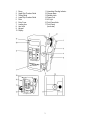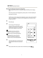
1
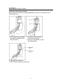
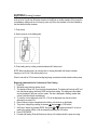
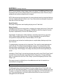
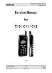
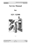
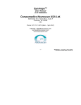
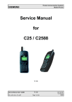
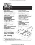
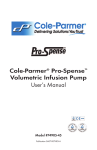
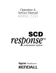
Operating Manual
Section I
General Information………………………………………………………2 & 3
Section II
Operating Procedures………………………………………………….4 thru 9
Section III
Intermittent Feeding Mode……………………………………………..10 & 11
Section IV
Alarms…………………………………………………………………11 thru 13
Section V
Cleaning………………………………………………………………….13 & 14
Section VI
Trouble Shooting Guide………………………………………………………15
Section VII
Factory Service………………………………………………………………..16
Section VIII
Specifications…………………………………………………………17 thru 19
Section IX
Limited Warranty………………………………………………………………20
1
SECTION I General Information
The KANGAROO PET® Enteral Feeding Pump is a rotary peristaltic pump designed to regulate
the flow rate of enteral feedings. Among the features provided by this pump are:
•
Small and lightweight for ambulatory operation – built in battery
•
Detachable charger base with permanently attached power chord and indicator light
•
“Quick-charge” feature fully recharges battery in 6 hours
•
Intermittent feeding mode allows repeated feedings at set periods
•
Wide range for dose to be delivered –
•
16-hour memory of all settings when pump is off
•
Large LED display and touch panel data entry
•
Low occlusion pressure. Pump will not overcome back pressure greater than
approximately 15 psi (103 kPa)
•
Integral pole clamp on base unit
•
Shut of and activation of audible and visible alarms when:
•
DC motor with intermittent operation
•
Volume delivered totalizer
•
Pump running indicator lights
-1-75 ml in 1 ml increments
-75-2000 ml in 5ml increments
-Feeding container is empty
-Feeding tube becomes occluded
-Drop sensor is blocked
-Battery low (alarms 15 minutes before pump shuts off)
-Unit is left in “HOLD” mode longer than 2-½ minutes
-Pump set is improperly loaded
-Self diagnosed problem, which requires technical servicing
-Preset dose has been delivered
-Pump motor malfunctions
•
Use of safety interlock pump sets to prevent free flow from inadvertent misleading of pump
set onto pump
WARNING: this KANGAROO® PET Pump requires the use of a KANGAROO Pump Set. The
pump will not operate if sets other than KANGAROO® Pump Sets are loaded onto the pump.
2
1.
2.
3.
4.
5.
6.
7.
8.
9.
10.
Pump
Upper Drip Chamber Guide
Tubing Guide
Lower Drip Chamber Guide
Rotor
Rotor Cover
Loading Arm
Arm Latch
Keypad
Display
11. Intermittent Feeding Indicator
12. Charger Base
13. Release Latch
14. Power Cord
15. AC Light
16. Pole Clamp Knob
17. Pole Clamp
(back view)
3
SECTION II Operating Procedures
Removing and Installing the Pump into the Charger Base
Below are general instructions for inserting the Kangaroo Pet® Pump into its charging
base.
Remove the pump from the charging base by pressing down on the latch and pulling the
pump away from the latch.
Install the pump onto the charging base by aligning the grooves in the pump body with the
guide in the charging base. Push pump onto the charging base until the pump is locked
into place by the latch.
ON
Power the pump
OFF
Turns the pump off. The battery will
charge even if the pump has been turned off
assuming that the pump is in the charger base
and the base is plugged into the wall outlet
Increases the rate, dose or interval as
desired. The numbers will change more
rapidly if the key is continuously depressed.
Decreases the rate, dose or interval as
desired. The numbers will change more
rapidly if the key is continuously depressed.
VOL
DOSE
Temporarily displays the accumulated volume
delivered since the last time the amount was
cleared.
When pressed, allows user to preset a dose to be delivered by pressing
4
or
.
SECTION II Operating Procedures
INT
Allows user to set start-to-start interval when pump is used in the intermittent feeding
mode. For details on implementing intermittent feeding, see Section III. The dot in the
upper left hand corner of the display will flash whenever the pump in the Intermittent
Feeding Mode. This dot is indicated by the INT label above the display.
CLR
Clears the value being displayed (volume delivered; rate, dose or interval setting). Volume
delivered cannot be cleared while pump is delivering a dose. During intermittent feeding
the volume delivered can be cleared only when the pump is between feedings, and in
HOLD mode.
START / HOLD
Starts pump rotor to deliver feeding formula to patient and alternately puts unit on HOLD.
HOLD is used to stop fluid flow to: (1) correct alarm condition – alarm is silenced; (2)
change the flow rate or other settings; (3) change pump set. When in HOLD mode, the
display flashes on and off. An alarm will occur if the pump has been placed in HOLD mode
and no keys are pressed for 2.5 minutes.
AC LIGHT (on charging base)
This indicator light is “on” whenever the charging base is plugged into the AC power outlet.
The indicator light will blink if the unit is in “quick-charge” mode.
Disposal of Pump Sets
Used pump sets shall be handled as follows:
To prevent employee exposure risk, the materials must be handled in accordance
with blood borne pathogen standards before being placed in an approved disposal
container.
Disposal must be performed in accordance with current medical practices or local
regulations in regards to disposal of infectious, biological waste.
5
SECTION II Operating Procedures
Installing the Pump Set into the Pump
Below are general instructions for inserting KANGAROO ® Pump Sets into the KANGAROO PET ®
Enteral Feeding Pump.
1. Open loading arm by unlatching it,
and rotating it clockwise into the
fully open position.
2. Insert bottom of drip chamber into
lower drip chamber guide.
3. Insert top of drip chamber into upper
drip chamber guide.
4. Insert tubing into loading arm.
5. Remove feeding connector protective cover.
6
SECTION II Operating Procedures
6. Slowly open clamp and fill entire line with fluid. If the pump is being used in a stationary setting
such as on an IV pole, then fill the drip chamber to the fill line on the drip chamber. If the pump is in
an ambulatory setting such as in its carrying case, only fill the drip chamber to the line indicated by
the label behind the drip chamber.
7. Close clamp.
8. Attach connector to the feeding tube.
9. Close loading arm by rotating counterclockwise until it latches shut.
NOTE: Never use the pump in its carrying case or carrying frame with the formula container
hanging on an IV Pole. Over delivery may occur.
When in use with an IV Pole assure feeding bag hangs a maximum vertical extension above pump.
Beginning Administration for Continuous or Dose Feeding
1. Press ON.
2. Wait while pump performs system check.
3. The display will show VOL, then the total volume delivered. The display will next show INT and
then the interval setting, and finally DOSE and the dose setting. The settings and their labels
are only displayed if they are non-zero values. The rate is displayed in flashing number after
volume; interval and dose are displayed.
4. To clear the volume delivered, press VOL; VOL will be displayed, then the last volume
delivered, then press CLR.
5. Rate of delivery may be changed when the delivery rate is shown on the display.
6. They rate is changed by pressing the increase , decrease , or CLR buttons.
7. Set Dose, if desired, by pressing DOSE, then press or to set dose desired. If an error is
made in the setting of Dose, it can be cleared by pressing the CLR button.
8. Press START/HOLD
9. Proceed with feeding. Dots will flash across the top of the display while the pump is running.
7
SECTION II Operating Instructions
NOTE: The rate of delivery setting is always shown on the display. The DOSE and VOL keys must
be pressed in order to view or change the dose or accumulated volume values. When the pump is
pumping the rate and dose settings cannot be changed.
NOTE: When a dose has been programmed, the volume delivered cannot be cleared until the dose
has been completely delivered or reset to zero. If any of these actions are attempted, the pump will
beep and won’t allow the change.
Normal Operation
With pump in charger base, insert hospital grade plug into an AC wall outlet.
Battery Operation
Unplugging the pump from the charger base or unplugging the charger base from an AC wall outlet
will automatically put the pump on battery power. A new battery, when fully charged, will operate
the pump for approximately 14 hours at 125 milliliters per hour.
Approximately 15 minutes prior to battery discharge, a low battery alarm will occur, (see alarm
section). When complete discharge occurs, the pump will automatically turn itself off. Before
turning itself off, the pump will beep 10 times and display “LO bAt” again.
As the batteries age, the time form low battery alarm to complete battery discharge may be less
than 15 minutes.
To recharge battery, insert pump unit into charger base. Then, insert the hospital grade plug into
an AC wall outlet. The battery will automatically begin charging. The recharge time for a fully
discharged battery is approximately 6 hours. Battery charging time may be reduced depending
upon pump usage. “Quick Charging” of the battery is shown by the AC indicator light flashing on
and off.
Interrupting a “Quick Charge” cycle and using the pump may result in a total “Quick Charge” time of
more than 6 hours when the pump is placed back onto the charger base. The pump will wait at
least 2 hours between the end of one “Quick Charge” cycle and the beginning of the next “Quick
Charge” cycle.
If the pump is turned on it will briefly turn on its audible alarm each time it is inserted into or
removed from the charger base.
Note: Do not charge the battery if the ambient temperature is less than 50°F (10°C)
The battery will charge continuously whenever the pump is plugged into an AC wall outlet, even
when the OFF button has been pressed. To insure that the pump is ready for ambulatory use, keep
the pump in its charger base and keep the charger base plugged into an AC wall outlet when not in
use. To be certain that power to all circuits has been disconnected, the power cord must be
unplugged from the AC wall outlet.
8
SECTION II Operating Procedures
Battery
The EPA Certified RBRC Battery Recycle Seal on the nickel-cadmium (NiCad)
battery contained in our product indicates Tyco Healthcare Group LP is
voluntarily participating in an industry program to collect and recycle these
batteries at the end of their useful life, when taken out of service in the United
States or Canada. The RBRC program provides a convenient alternative to
placing used NiCad batteries into the trash or the municipal waste stream, which may be illegal in
your area. Please call 1-800-8-BATTERY for information on the NiCad battery recycling and
disposal bans/restrictions in your area. Tyco Healthcare Group LP’s involvement in this program is
a part of our commitment to preserving our environment and conserving our natural resources.
The battery pack can be removed for collection and recycling when it fails to function properly. To
remove the battery, unplug the unit from the AC wall unit, remove the seven screws from the back
of the pump and take off the back cover pieces. Unplug the battery from the pump, remove the
grounding wire from the battery retaining plate and take out the battery.
Replacement battery packs are available from Tyco Healthcare Group LP (See Section IV –
Factory Services).
WARNING: REPLACE THE BATTERY PACK ONLY WITH THE SAME TYPE AND RATING OF
BATTERY.
NOTES:
1. Charging the batteries at temperatures greater than 105°F (40°C) will reduce the battery
charge capacity and operating time on the battery power.
2. Occasionally let the pump run until the LOW BATT alarm occurs and then recharge in
order to maximize battery operating time.
Ambulatory Use
The pump has been designed to fit into a frame and carrying case for convenient bedside or
ambulatory use. The pump maintains its flow rate accuracy when correctly installed in the frame. If
the pump is turned on it will briefly turn on its audible alarm each time it is inserted into or removed
from the frame.
Make sure pump is correctly installed in the frame to maintain flow rate accuracy. A charging
cord is also available to allow charging the pump while it is in the frame. To charge the pump,
connect the cord between the pump and the charger base.
9
SECTION III Intermittent Feeding Mode
The KANGAROO PET® Feeding Pump offers an additional feature for the user – Intermittent
Feeding Mode. This mode of operation allows the patient to be fed at scheduled intervals
automatically. The user enters dose and delivery rate as normal; the user then enters the interval
for the feedings. Interval time is defined as the time from the start of one feeding until the start of
the next feeding. In other words, the interval time is the time of the feeding + the time between the
end of the feeding and the start of the next feeding. The examples given will explain interval time
further.
Beginning Administration for the Intermittent Feeding
Below are the general instructions for setting the pump up for operation in an intermittent feeding
mode.
1. Press ON.
2. Wait while the pump performs system check.
3. The display will show VOL, then the total volume delivered. The display will next show INT and
then the interval setting, and finally DOSE and the dose setting. The setting and their labels
are only displayed if they are non-zero values. The rate is displayed in flashing numbers after
volume, interval and dose are displayed.
4. To clear the volume delivered, press VOL; VOL will be displayed, then the last volume
delivered, then press CLR.
5. Rate of delivery may be changed when the delivery rate is shown on the display.
6. The rate is changed by pressing the increase , decrease , or CLR buttons.
7. Set Dose by pressing DOSE, then press or to set dose desired. If an error is made in the
setting of the Dose, it can be cleared by pressing the CLR button.
8. Press the INT button. The interval between feedings can now be entered in 1-hour increments
from 1 to 24 hours. The pump will beep and won’t allow entry of combinations of rate, dose and
interval that are not possible to achieve (see example 2).
9. Setting the interval and dose to any non-zero values puts the pump into the Intermittent
Feeding Mode, which is indicated by a flashing dot in the upper left hand corner of the display.
10. Press START/HOLD to begin the first feeding. Between feedings, a series of dashes will flash
on the display to indicate the pump is operating, but the rate is not displayed. The delivery rate
is only shown when the pump is delivering formula.
10
SECTION III Intermittent Feeding Mode
Example 1:
A user sets a rate of 400 ml/hr, dose of 800 ml, and an interval of 6 hours. This will result
in the pump delivering 800 ml of fluid every 6 hours. Since the rate is 400 ml/hr, it will take
2 hours to deliver the set dose, and the pump will then wait 4 hours before starting to
deliver the next 800 ml.
Example 2:
A user wants to set a rate of 200 ml/hr, a dose of 1000 ml, and an interval of 4 hours. This
combination is not a valid one because it will take 5 hours to deliver the 1000 ml dose, at a
rate of 200 ml/hr. Once this rate and dose are selected, the pump will only allow the user
to enter intervals from 5 to 24 hours. In this case, the interval will change from 0 to 5 with
the first press of the button, and then from 5 to 6 to 7 up to 24. Using the button will
take the interval from 24 to 23 to 22 and down to 5. The next press of the button will
change the interval from 5 to 0. In this way, the pump does not allow unachievable settings
to be entered.
NOTE: When the pump is pumping, the volume delivered cannot be cleared, and the rate, dose
and interval settings cannot be changed. The volume delivered can only be cleared between
feedings if the unit is in the HOLD mode. If any of these actions are attempted, the pump will beep
and won’t allow the change.
Section IV Alarms
The KANGAROO PET® Enteral Feeding Pump has been designed to provide audible and visible
alarms under several conditions where proper performance cannot be maintained. The visible
alarm is in the form of a message shown on the display. When an alarm occurs, press the
START/HOLD button on the pump to silence the audible alarm and perform the necessary
procedures to correct the alarm condition. The visible display will continue to flash the alarm
message until the START/HOLD button is pressed again.
No Set (no Set)
The feeding set is not installed or is installed improperly. See Operating Procedure for installation
instructions.
This alarm can occur in one of three situations:
A. If the pump is started before the set is properly loaded.
B. If the set becomes dislodged from the pump while it is pumping.
C. If the set is not properly installed for 5 minutes while in the HOLD mode.
11
SECTION IV Alarms
Flow Error (FLO Err)
A. The Feeding container is empty. To correct the situation, if more feeding is required, refill
the container with the desired amount of formula and follow the steps in the Operating
Procedures of this manual.
B. The feeding container, the feeding set tubing, or the feeding tube itself has become
occluded beyond the pump’s capability to pump. Alarm will activate at approximately 15 psi
(103 kPa). Determine where in the system the occlusion has occurred and correct the
occlusion condition.
C. The drop sensors are blocked and will not be able to detect drops and the come through
the drip chamber. To correct this condition, check the drop sensor on inside of upper drip
chamber guide and clean off any material that may be blocking sensor.
D. In ambulatory use, keep level of liquid in drip chamber as low as possible in order to
minimize false “Flow Error” alarms. Do not fill the drip chamber above the “Ambulatory fill
line” shown on the pump.
Low Battery (LO bAt)
This alarm is activated when the battery begins to run down. The low battery alarm occurs
approximately 15 minutes before complete discharge. When complete discharge occurs, the pump
automatically turns itself off.
To correct this condition, plug the pump into the charger base and plug the hospital grade plug into
an AC wall outlet. When the pump is connected to the charger base, and the charger base is
plugged into an AC wall outlet, it will continue to operate and charge the battery at the same time.
Once the low battery alarm has sounded, it will take approximately 6 hours to fully recharge.
Battery charging time may be reduced depending upon pump usage.
Hold Error (HLd Err)
If the pump is left in the hold mode for approximately 2-1/2 minutes, the “Hold Error” will alarm.
System Error (Sys Err)
The rotor or the rotor sensor is not operating properly. Return pump for technical service.
Internal Problem (8 8 8 8)
An internal circuit problem has been detected. Return pump for technical service.
12
SECTION IV Alarms
Dose Delivered (dOSE deL)
Preset dose has been delivered to patient.
When preset dose has been delivered, perform one of the following:
--- Repeat the dose amount by clearing the volume delivered and then pressing START/HOLD.
--- Cancel the dose feature by pressing DOSE and CLR, and START/HOLD.
--- To feed additional volume, increase the dose amount by pressing DOSE, then until new dose
is displayed and then press START/HOLD.
---Turn pump off.
ALARM TEST
The audible alarm and the pump set safety interlock may be tested by performing the following
steps:
1. Turn the pump on and set any non-zero rate.
2. Remove the pump set from the pump (if loaded) and push the START/HOLD key.
3. The pump should generate the audible alarm and display “no Set”
WARNING: IF ALARM DOES NOT SOUND DURING ALARM TEST, OR WHEN ANY ALARM
CONDITION EXISTS, SEE “NO AUDIBLE ALARM” SYMPTOM IN TROUBLESHOOTING GUIDE.
SECTION V Cleaning
*CAUTION
--- Disconnect pump and base from AC power source before cleaning.
--- Do not immerse pump or base in cleaning solution.
--- A mild detergent or isopropyl alcohol may be used for general cleaning.
--- If necessary, a hypochlorite solution (10 parts water to 1 part bleach) can also be used for
cleaning the pump or base. However, repeated cleaning with this solution can damage the plastic
and labeling of the pump base.
HOUSING
--- Clean outside surface with a damp (but not saturated) cloth or sponge.
--- Avoid excess moisture near 4-pin connectors and battery access door.
---Keep pump and base in upright position as much as possible.
13
SECTION V Cleaning
DROP DETECTOR
--- Clean the drop sensors in the upper drip chamber guide with cotton swabs and warm soapy
water or isopropyl alcohol.
--- Be sure sensor areas are clean.
ROTOR AND ROTOR COVER ASSEMBLY
--- Remove the two screws that hold the rotor cover in place and gently remove rotor cover.
--- Loosen rotor set screw wit a 5/64” allen wrench and gently pull rotor forward off shaft.
--- Clean rollers thoroughly with warm soapy water, or isopropyl alcohol if necessary.
--- Be sure all parts of rotor are completely dry before putting it back onto shaft.
--- To replace rotor, align set screw on hub of rotor with the flattened section of the output shaft.
--- Push rotor into place and tighten set screw. (Do not overtighten.)
--- Reinstall rotor cover and tighten screws.
*CARE SHOULD BE TAKEN THAT NO SOLUTION GETS INSIDE THE PUMP OR BASE, AS
DAMAGE TO ELECTRICAL COMPONENTS COULD RESULT. PROLONGED EXPOSURE TO
ALCOHOL OR OTHER STRONG CLEANSERS COULD RESULT IN DAMAGE TO THE PUMP
OR BASE HOUSINGS.
14
SECTION VI Troubleshooting Guide
Listed below are some of the probable causes of alarm conditions and their corrections.
Symptom
No Set
Alarm
(no SEt)
Probable Cause
-Pump has been
Improperly placed onto
Pump.
Corrections
-Check to make sure that only KANGAROO® Pump Set has
been placed onto pump.
-Check to make sure that the pump set has been properly
positioned on the pump.
Flow Error
Alarm
(FLO Err)
-Feeding container is
Empty.
Refill feeding container. If feeding set has been in use for 24
hours, replace.
-Feeding tube or feeding
set tubing is occluded.
Locate point of occlusion and correct. NOTE: Occlusion may
occur upstream or down stream from pump.
• Feeding Container
• Feeding Pump Set (control clamp closed)
• Feeding Tube – feeding tube should be checked for
obstruction.
Drip Chamber walls are
coated with feeding
formula.
Check to make sure formula is not preventing drop detector
from proper operation. If formula cannot be removed from
inside walls of chamber via chamber manipulation, replace
feeding set.
Sensor in upper drip
chamber guide is blocked.
Check to make sure black surface of drip chamber guide is free
of dried formula. Remove any deposits by using a cotton swab
dampened with warm soapy water or isopropyl alcohol.
Insert pump into charge base and plug power cord into wall
outlet.
Low Battery
Alarm
(LO bAt)
Hold Error
Alarm
(HLd Err)
System
Error Alarm
(SYS Err)
Internal
Circuit
Problem
Alarm
(8 8 8 8 )
Dose
Delivered
Alarm
(dOSE dEL)
Battery has been run
Down.
No Audible
Alarm
Battery is fully
discharched.
Pump has been left in the
hold mode for over 2.5
minutes.
Problem with rotor, rotor
position sensing or other
rotor circuit problem.
Problem with internal
pump circuitry.
Press START/HOLD to silence alarm, then press START/HOLD
again to restore flashing rate display, and press START/HOLD
again to restart pump.
Return pump for technical service.
Preset dose has been
delivered to patient.
Repeat the dose amount by clearing the volume delivered; OR
cancel the feature by pressing DOSE and CLR; OR to feed
additional volume, increase the dose amount by pressing
DOSE, then until new dose is displayed; OR turn the pump
off.
Charge battery for a minimum of 8 hours.
Alarm circuitry failure.
Return pump for technical service.
Return pump for technical service.
15
SECTION VII Factory Service
A. In the event that is necessary to return a unit for repair, please observe the following:
1. Call Customer Service at (800) 448-0190 for Authorized Return Number and
shipping instructions.
2. Pack the instrument carefully and ship to:
Tyco Healthcare Group LP
98.6 Faichney Drive
Watertown, NY 13601
B. To place an order for repair parts or if technical assistance is required, call (800) 448-0190.
Canada
500 Trans Canada Highway
Pointe-Claire, Qc
H9R5H8
Telephone: (416) 479-5500
Technical information will be made available on request to allow the users’ appropriately qualified
technical personnel to repair the parts of the KANGAROO PET® Service Manual for more service
information.
16
SECTION VIII Specifications
Type Infusion Device
Volumetric
Pumping Mechanism
Rotary Peristalic
Pump Set Required
KANGAROO® Feeding Pump Administration Sets
Infusion Rate Range
1-75 ml/hr in 1 ml increments
75-400 ml/hr in 5ml increments
Dose Range
1-75 ml/hr in 1 ml increments
75-400 ml/hr in 5ml increments
Accuracy
± 10% of selected flow rate
Occlusion Pressure
15 psi (103 kPa) Nominal
Alarms
• Flow Error
• Low Battery
• Hold Error
• No Set
• System Error
• Dose Delivered
• Internal Circuit Problem
Battery
• Rechargeable
• Automatically charges when pump is plugged into charger base
• “Quick Charge” feature will recharge fully discharged battery in approximately 6 hours.
• A new battery, when fully charged, will operate for approximately 14 hours at 125 milliliters
per hour rate.
Dimensions
Pump:
Pump with Charger:
5.75”H x 3.81”W x 2.00”D
(14.61cm x 9.68cm x 5.08cm)
6.25”H x 4.50”W x 4.60”D, (15.88cm x 11.43cm x 11.68cm)
17
SECTION VIII Specifications
Weight
Pump:
Charger Base:
Approximately 1.4 lb (635 g)
Approximately 2.08 lb (944 g)
Power Requirements
US: 120V, 60HZ, 1AMP
Japan: 100V, 50/60HZ, 1AMP
Memory of Settings when Pump is OFF
16 hours for all settings
Operating Temperature
50°F to 105°F (10°C to 40°C) If Charging
40°F to 105°F (5°C to °40°C) If Pumping
Transport and Storage
(not to exceed 30 days)
32° to 122°F (0° to 50°C)
10-95% RH, non-condensing
In the event that the environmental conditions for transport and storage are
exceeded, return the unit for factory service.
In the event that the specified storage time is exceeded, within the environmental
limits specified, perform the performance tests prior to use. Refer to the
KANGAROO PET® Pump service manual for servicing information.
Accessories
The KANGAROO PET® Enteral Feeding System consists of:
KANGAROO PET® Feeding Pump with Charger Base --- 8884350003
KANGAROO PET® Carrying Case with Frame --- 8885350409
KANGAROO PET® Charging Cable --- 8884350490
The KANGAROO PET® Feeding Pump is to be used only with KANGAROO®
Pump Sets
UL Listing
Medical Electrical Equipment KANGAROO PET®
1 Classified with respect to electrical shock, fire and
mechanical hazards only in accordance with UL2601-1
2 Classified with respect to electrical shock, fire, mechanical and other
specified hazards only in accordance with CAN/CSA C22.2 NO 601.1
<47DA>
18
SECTION VIII Specifications
Type of Protection Against Electrical Shock
Class 1, Internally Powered Equipment
Charger disconnect device
To disconnect AC power it is necessary to unplug the hospital grade plug from the AC wall
outlet.
Degree of Mobility
Portable
Mode of Operation
Continuous
Degree of Protection Against Ingress of Fluids
Drip-Proof-IPX1
Degree of Protection Against Ingress of Flammable Anaesthetic Mixtures
Not suitable for use in the presence of flammable anaethetic mixture with air, oxygen or
nitrous oxide.
Minimizing EMC
The KANGAROO PET feeding pump is designed to minimize the effects of uncontrolled
electromagnetic interference and other types of interference. When using the KANGAROO
PET feeding pump, avoid use of equipment that causes erratic operation or degradation in
performance.
19
SECTION IX Limited Warranty
Tyco Healthcare Group LP (hereinafter referred to as T.H.L.P.) warrants that each KANGAROO
PET® Enteral Feeding Pump will be free from defects in materials and workmanship under normal
use and service for a period of one year from the date of delivery by T.H.L.P. to the first purchaser.
If any such defect occurs during the warranty period, the aforesaid purchaser should communicate
directly with T.H.L.P. If returned to T.H.L.P., T.H.L.P will arrange for repairs or replacement within
the terms of the warranty. The defective pump should be promptly returned properly packaged,
postage prepaid. Loss or damage in return shipment to T.H.L.P. shall be at Purchaser’s risk.
This warranty shall not apply to, and T.H.L.P. shall not be responsible for, any loss arising in
connection with the purchase or use of any such pump which has been repaired by anyone other
than an authorized T.H.L.P. representative or altered in any way so as, in T.H.L.P.’s judgment, to
affect its stability or reliability or which has been subject to misuse, negligence or accident, or
which has had the serial or lot number altered, defaced or removed, or which has been used
otherwise than in accordance with the instructions furnished by T.H.L.P. T.H.L.P. neither assumes
nor authorizes any representative or other person to assume for it any other liability in connection
with the sale of such pumps.
T.H.L.P. DISCLAIMS ALL OTHER WARRANTIES, EXPRESS OR IMPLIED, INCLUDING ANY
IMPLIED WARRANTY OF MERCHANTABILITY OR OF FITNESS FOR A PARTICULAR
PURPOSE OR APPLICATION OTHER THAN THOSE EXPRESSLY SET FORTH IN THE
APPROPRIATE PRODCUT LABELING OR USER INFORMATION MANUAL. IN NO EVENT WILL
T.H.L.P. BE LIABLE FOR ANY INCIDENTAL, INDIRECT OR CONSEQUENTIAL DAMAGES IN
CONNECTION WITH THE PURCHASE OR USE OF ITS PRODUCTS.
20