1
Instruction Manual MN191003EN
EffectiveAugust2013
Installation and Service Manual
Fleet AC Level 2 Electric Vehicle
Supply Equipment (EVSE)
Contents
Description
1.
• •
Page
Important Safety Instructions- Please Read .. 2
2. Symbols and Definitions ................. 2
3. About the Fleet AC Level 2 EV Charging
Station ............................... 3
4. Installing the Electrical Service ............ 4
5.
6.
7.
8.
9.
Instructions for Opening Door ............ 5
Installing to the Premise ................. 5
Termination and Configuration ............. 6
Confirming Installation and First Use ....... 7
Specifications ........................ 10
10. Appendix ............................ 11
Powering Business Worldwide
for Upgraded Charger, 220v ?Oamps
For more information, visit
www.eaton.com/plugin, call
1-855-ETN-EVSE (1-855-386-3873).
or call your local Eaton sales office.
Installation and Service Manual
Fleet AC Level 2 Electric Vehicle
Supply Equipment (EVSE)
Instruction Manual MN191003EN
Effective August 2013
1. Important Safety Instructions - Please
Read
A
WARNING ELECTRICAL
THIS EQUIPMENT SHOULD BE INSTALLED, ADJUSTED, AND SERVICED
BY QUALIFIED ELECTRICAL PERSONNEL FAMILIAR WITH THE CONSTRUC·
TION AND OPERATION OF THIS TYPE OF EQUIPMENT AND THE HAZARDS
INVOLVED. FAILURE TO OBSERVE THIS PRECAUTION COULD RESULT IN
DEATH OR SEVERE INJURY.
READ THIS MANUAL THOROUGHLY AND MAKE SURE YOU UNDERSTAND
THE PROCEDURES BEFORE YOU ATTEMPT TO OPERATE THIS EQUIPMENT.
THE PURPOSE OF THIS MANUAL IS TO PROVIDE YOU WITH INFORMATION
NECESSARY TO SAFELY OPERATE, MAINTAIN, AND TROUBLESHOOT THIS
EQUIPMENT. KEEP THIS MANUAL FOR FUTURE REFERENCE.
DO NOT USE THIS PRODUCT IF THE EV CABLE IS FRAYED, HAS DAMAGED
INSULATION OR ANY OTHER SIGN OF DAMAGE.
DO NOT USE THIS PRODUCT IF THE ENCLOSURE OR THE EV CONNECTOR
IS BROKEN, CRACKED, OPEN, OR SHOW ANY OTHER INDICATION OF DAMAGE.
DO NOT USE THIS PRODUCT IF THE EV'S CHARGING COUPLER/INLET IS
BROKEN/DAMAGED.
Definitions
AC - Alternating Current. The type of power available in most build·
ings and on utility poles. The Fleet Level 2 EVSE protects Users and
vehicles by allowing AC power to flow through it to the vehicle. The
vehicle then converts the AC to DC (Direct Current) to charge the
traction battery.
ADA - Americans with Disabilities AC1
ALC - Available Line Current. The charger tells the vehicle through
the J1772™ connector's pilot pin how much current (in amperes) it
is allowed to pull on the circuit. This allows the vehicle to not exceed
the circuit's maximum current rating.
Disconnect Signal Redundancy - Provides redundancy to the disconnect signal for quick response in ending higher energy charging
applications. The redundancy feature quickly opens the EVSE contactor, removing energy transfer to the vehicle.
EVSE - Electric Vehicle Supply Equipment. EVSE is a general term
used for all of the equipment used to supply electricity to the vehicle, such as the Eaton Fleet AC Level 2 EVSE.
GFCI - Ground Fault Current Interrupter. GFCI protects Users from
faults involving leakage currents going to ground, rather than the
proper return path of the circuit.
J1772™ - The SAE Recommended Practice for conductive charging
of hybrid and electric vehicles. This standard spells out the physical
dimensions of the J1772 connector and the pilot communication
between the plug-in vehicle and EVSE.
PREMISE VENTILATION NOT REQUIRED.
Pilot - The signal through the J1772 connector. This signal tells both
the vehicle and the EVSE when both are ready to charge and how
much current it is allowed to pull. This signal is a SAE standard.
THE INFORMATION CONTAINED IN THIS MANUAL IS SUBJECT TO CHANGE
WITHOUT NOTICE.
Plug Session - The time while the EVSE is plugged into a vehicle.
It starts by plugging in the J1772 connector and ends when unplugging the same connector.
DO NOT DRILL HOLES OR MODIFY ENCLOSURE SUCH THAT THE NEMA/IP
RATINGS ARE COMPROMISED.
SAE - Society of Automotive Engineers. The group that organizes
and leads committees of transportation experts to create standards,
such as J1772, for the transportation industry.
2. Symbols and Definitions
TB - The Terminal Block is where the incoming field power will be
terminated in the EVSE unit.
INTENDED FOR USE WITH PLUG-IN ELECTRIC VEHICLES ONLY.
A
WARNING ELECTRICAL
THIS SYMBOL INDICATES HIGH VOLTAGE. IT CALLS YOUR ATTENTION TO
ITEMS OR OPERATIONS THAT COULD BE DANGEROUS TO YOU AND OTHER
PERSONS OPERATING THIS EQUIPMENT. READ THE MESSAGE AND FOL·
LOW THE INSTRUCTIONS CAREFULLY.
& WARNING
INDICATES A POTENTIALLY HAZARDOUS SITUATION WHICH, IF NOT
AVOIDED, CAN RESULT IN SERIOUS INJURY OR DEATH.
& CAUTION
INDICATES A POTENTIAL HAZARDOUS SITUATION WHICH, IF NOT AVOID·
ED, CAN RESULT IN MINOR TO MODERATE INJURY, OR SERIOUS DAMAGE
TO THE EQUIPMENT. THE SITUATION DESCRIBED IN THE CAUTION MAY,
IF NOT AVOIDED, LEAD TO SERIOUS RESULTS. IMPORTANT SAFETY MEA·
SURES ARE DESCRIBED IN CAUTION (AS WELL AS WARNING).
& IMPORTANT
INDICATES A PARTICULAR ITEM OR INSTRUCTION THAT IS IMPORTANT TO
CONSIDER.
Save These Instructions
2
EATON www.eaton.com
Traction Battery - The large battery on a plug-in electric vehicle that
is used to store and release energy for propulsion. This is different
than the 12V battery that is used to start the vehicle initially and run
accessories such as the radio.
UI - The User Interface part of the unit.
Installation and Service Manual
Fleet AC Level 2 Electric Vehicle
Supply Equipment (EVSE}
3. About the Fleet AC Level 2 EV Charging
Station
Eaton's Fleet AC Level 2 charging station is Electric Vehicle Supply
Equipment (EVSE) and is compatible with the Society of Automotive
Engineers J1772™ standard for charging plug-in hybrid and all-electric vehicles.
The Fleet Level 2 EV Charging Station has several safety features:
• Protects Users with interlocked power - the cable and pins have
no power on them until the connector is safely plugged into a
vehicle.
• Protects Users from temporary faults - and automatically resets*
so no User interaction is needed.
• Provides overcurrent protection and will trigger a temporary fault
in the event a vehicle tries to draw too much current.
Instruction Manual MN191003EN
Effective August 2013
ADA Standards for Accessible Design
It is very important to consider all STANDARDS FOR ACCESSIBLE
DESIGN for Americans with Disabilities when choosing the location
and placement of all Electric Vehicle Supply Equipment.
The Department of Justice has assembled an online version of the
official 2010 Standards to increase its ease of use. This version
includes:
2010 Standards for State and Local Government Facilities
Title II; and
2010 Standards for Public Accommodations and Commercial
Facilities Title Ill.
For information about the ADA, including the revised 2010 ADA regulations, please visit the Department's website www.ADA.gov; or, for
answers to specific questions, call the toll-free ADA Information Line
at 800-514-0301 (Voice) or 800-514-0383 (TTY).
• Allows integration into authorization and management systems
- keeping only authorized personnel able to use units and power
usage levels to predefined levels.
• See section 'Specifications' for more details.
* Automatic Reset feature must be enabled during installation see page 8 for more information.
Moving, Transporting and Storage Instructions
Store this unit indoors and in its original packaging until it is ready to
be installed. Storage temperature should be between -30° and
80° C. When moving or lifting the unit, always grasp the unit enclosure. NEVER attempt to lift, move, or carry the unit by the EV cable.
Improper storage or handling may cause damage to the unit.
Before You Begin
A WARNING ELECTRICAL
WARNING - ONLY QUALIFIED PERSONNEL FAMILIAR WITH THE
OPERATION AND CONSTRUCTION OF THIS EQUIPMENT SHOULD INSTALL,
ADJUST, MODIFY, AND SERVICE THIS EQUIPMENT. FAILURE TO FOLLOW
THE INSTRUCTIONS COULD RESULT IN SEVERE BODILY INJURY OR DEATH.
&. IMPORTANT
THE USER IS RESPONSIBLE FOR CONFORMING TO ALL LOCAL AND
NATIONAL ELECTRIC CODE® STANDARDS APPLICABLE IN THE ENVIRONMENT THAT THE EVSE IS BEING INSTALLED AND COMMISSIONED.
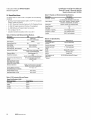
Replacement Parts List
Table 1. Replacement Parts List.
Part
Part Number
Protection and Control Board PCBA
Consult Factory
70 A Cable / Connector Assembly
91 C5363G04*
Ribbon Cable for User Interface
91C5361G01
User Interface Unit
91C5360G01
Contactor 50A
91C5362G10
Contactor 70A
91C5362G02
*consult with your local sales office to confirm availability
EATON www.eaton.com
3
Installation and Service Manual
Fleet AC Level 2 Electric Vehicle
Supply Equipment {EVSE)
Instruction Manual MN191003EN
Effective August 2013
A
4. Installing the Electrical Service
Checking the Electrical Requirements
The National Electric Code®, Article 625.21 states "Overcurrent
protection for feeders' and branch circuits supplying electric vehicle
supply equipment shall be sized for continuous duty and shall have a
rating of not less than 125 percent of the maximum load of the electric vehicle supply equipment." A load study of the location's electrical service may be needed to determine the availability of adequate
electrical service. Take the nameplate amperage rating of the Fleet
Level 2 EVSE, and multiply by 125% for the minimum upstream circuit protection needed.
Check your local jurisdictions for any other electrical requirements.
WARNING ELECTRICAL
WARNING - LOCKOUT/TAGOUT ALL ELECTRICAL SOURCE CIRCUITS
FEEDING THE UNIT(S) IN THE OPEN POSITION BEFORE BEGINNING
WIRING OR TERMINATIONS. FAILURE TO FOLLOW THE INSTRUCTIONS
COULD RESULT IN SEVERE BODILY INJURY OR DEATH.
6 WARNING
THIS UNIT IS RATED FOR INDOOR OR OUTDOOR INSTALLATION. IF THIS
UNIT IS MOUNTED OUTDOORS, THE HARDWARE FOR CONNECTING THE
CONDUITS TO THE UNIT MUST BE RATED FOR OUTDOOR INSTALLATION
AND BE INSTALLED PROPERLY TO MAINTAIN THE PROPER NEMA 3R RATING ON THE UNIT.
Running the Wires
Once the proper electrical overcurrent devices have been installed,
wires need to be run from it to the EVSE. For a typical installation,
the only field wires will be for the incoming electrical service. The
Fleet AC Level 2 EVSE operates on a single-phase service - two
hots, and one ground.
Note: Use Copper Conductors ONLY.
& IMPORTANT
- THE 48A FLEET LEVEL 2 EVSE REQUIRES A DEDICATED
208/240 VAC 60A UPSTREAM BREAKER.
- THE 70A FLEET LEVEL 2 EVSE REQUIRES A DEDICATED
208/240VAC 90A UPSTREAM BREAKER.
Notes:
The End user is responsible for all Arc-Flash Hazard category
information.
For units with circuit breaker 60A or greater, end user must
install disconnect means consistent with NEC requirements article 625.23 (USA) and CEC Part 1 Section 86 (Canada).
This EVSE is not suitable for location as identified in NEC
article 500 (Classified Locations) and CEC Part 1 Section 86-102
(Hazardous Locations).
4
EATON www.eaton.com
& IMPORTANT
CONFIRM WITH THE LOCAL ELECTRICAL REllUIREMENTS FOR THE GAUGE,
TEMPERATURE RATING, AND TYPE OF WIRE MATERIAL USED FOR THE
OVERCURRENT RATING FOUND BELOW. THE CHART SHOWS A GENERAL
RECOMMENDATION.
Table 2. Electrical Wire Chart
Style
Nameplate
Upstream
Breaker
Size
Suggested
Wire Type
Suggested Wire
Temp Rating
Fleet Level 2
SNR3C
48A
60A
Copper
75 degrees C
SNR3D
70A
90A
Copper
75 degrees C
Installation and Service Manual
Fleet AC Level 2 Electric Vehicle
Supply Equipment (EVSE)
5. Instructions for Opening Door
Instruction Manual MN191003EN
Effective August 2013
6. Installing to the Premise
.&. IMPORTANT
&WARNING
BEFORE OPENING THE FLEET LEVEL 2 EVSE INSURE THAT THE PROPER
LOCK OUT TAG OUT PRO CEO URE HAS BEEN PERFORMED ON THE
UPSTREAM POWER TO THE UNIT.
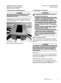
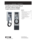
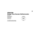
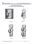
First ensure the power is off and the front monitor is blank as shown
in Figure 1 below. To open the Fleet Level 2 EVSE, locate the two
latch screws indicated by the arrows in Figure 1. Remove these
screws and open the box.
THINGS TO CONSIDER BEFORE CHOOSING A LOCATION TO MOUNT THE
UNIT:
1. STANDARDS FOR ACCESSIBLE DESIGN.
2. CONSULTATION WITH AN ARCHITECT MAY BE NEEDED IN ORDER
TO CONFORM TO ALL GOVERNING STANDARDS FOR LOCATION AND
PLACEMENT OF ELECTRIC VEHICLE SUPPLY EQUIPMENT.
3. LOCATION OF AN AVAILABLE MOUNTING SUPPORT - THE WALLMOUNT UNIT MUST BE ANCHORED INTO A MOUNTING SUPPORT
STUD OR SOLID CONCRETE WALL, USING MOUNTING HARDWARE
THAT IS APPROPRIATE FOR THE SURFACE ON WHICH YOU ARE
MOUNTING. DO NOT MOUNT THIS UNIT TO A STUCCO/DRVWALlJ
WALLBOARD.
4. LOCATION OF AN AVAILABLE ELECTRICAL SOURCE - POWER WIRES
MUST BE RUN THROUGH AN APPROVED CONDUIT OR JACKET
FROM THE CIRCUIT PANEL TO THE UNIT.
5. LOCATION OF THE VEHICLE'S CHARGING INLET WHILE PARKED
-- THE UNIT MUST BE LOCATED SO ITS RESPECTIVE CABLE LENGTH
IS CORRECTLY SIZED TO WHERE THE VEHICLE'S INLET IS
ACCESSIBLE FOR PLUG-IN WITHOUT UNDUE MANEUVERING.
6. HEIGHT OF THE CONNECTOR DOCK MUST BE BETWEEN 24 AND 48
INCHES WHEN INSTALLED TO COMPLY WITH ADA AND NEC
STANDARDS.
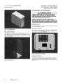
Mounting the Eaton Fleet EVSE
Once a proper site has been chosen and the electrical service has
been run to the location, you can begin installation. The installation
requires installing the Fleet Level 2 EVSE to a wall or a unistrut with
cross braces.
Figure 1. Fleet Level 2 EVSE Door Screws.
.&. CAUTION
DO NOT MOUNT UNIT TO ONLY STUCCO/DRYWALL/WALLBOARD. DO NOT
USE TOGGLE BOLTS, ZIP ANCHORS, NOR PLASTIC WALL ANCHORS MEANT
FOR THESE MATERIALS BECAUSE THEY DO NOT HAVE THE STRENGTH
NEEDED TO SUPPORT THE UNIT. THE UNIT MUST BE MOUNTED TO A
SOLID SUPPORT SUCH AS: WOOD, CONCRETE WALL, CONCRETE BLOCK
WALL, OR EQUIVALENT.
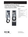
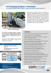
Stud Mounting
Locate wooden stud that you wish to mount the Eaton Fleet EVSE
to. Using 1/4-20" x 3" long lag screws, mount the EVSE using Stud
mounting holes seen in Figure 2. Mount the EVSE securely to the
stud using four 1/4-20 flange nuts.
Unistrut Mounting using a strut with cross braces
Use a single vertical strut with horizontal cross braces 14" apart.
Mount the EVSE using 1/4-20 x 3" long lag screws and the four
corner holes labeled unistrut mounting in Figure 2. Mount the EVSE
securely to the cross braces using four 1/4-20 flange nuts.
EATON www.eaton.com
5
Installation and Service Manual
Fleet AC Level 2 Electric Vehicle
Supply Equipment (EVSE)
Instruction Manual MN191003EN
Effective August 2013
7. Termination and Configuration
A
WARNING ELECTRICAL
WARNING - LOCKOUT/TAGOUT ALL ELECTRICAL SOURCE CIRCUITS
FEEDING THE UNIT(S) IN THE OPEN POSITION BEFORE BEGINNING
WIRING OR TERMINATIONS. FAILURE TO FOLLOW THE INSTRUCTIONS
COULD RESULT IN SEVERE BODILY INJURY OR DEATH.
WARNING - ONLY QUALIFIED PERSONNEL FAMILIAR WITH THE
OPERATION AND CONSTRUCTION OF THIS EQUIPMENT SHOULD INSTALL,
ADJUST, MODIFY, AND SERVICE THIS EQUIPMENT. FAILURE TO FOLLOW
THE INSTRUCTIONS COULD RESULT IN SEVERE BODILY INJURY OR DEATH.
Wire Terminations
For a typical installation, the only field wire terminations will be the
incoming electrical service wires.
Electrical Service Wires
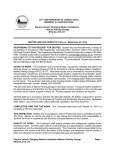
Figure 2. EVSE Mounting
Mounting Cable Hanger
Terminate the incoming electrical service wires to the Fleet Level 2
EVSE's contactor and grounding bar., following the designations for
each wire; L 1, L2, and G (see Figure 4).
Using the two 1/4-20 Flange nuts (70222DAN09) provided with the
cable hanger, mount the hanger securely to the wall using two 1/4-20
studs. (Stud placement is approximately 3.75" below EVSE mounting
studs or cross braces).
Figure 4. Electrical Service Wiring.
Grounding Instructions
Figure 3. Cable Hanger
6
EATON www.eaton.com
This product must be connected to a grounded, metal, permanent
wiring system; or an equipment-grounding conductor must be run
with the circuit conductors and connected to the equipment grounding terminal.
Installation and Service Manual
Fleet AC Level 2 Electric Vehicle
Supply Equipment (EVSE)
Instruction Manual MN191003EN
Effective August 2013
8. Confirming Installation and First Use
fifllllflH
lnt:illHlh:H
Ov1nrM1c? i!Jutt@n
o.f'!ft liontm)
Fl11mot@lv
Cotmoll@d
Tornporarv
fiault
llUilHtOI'
lndit'lfltor
Temporary
ReHt Button
!1'41ght Bunonl
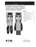
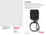
ICON Status
ICON
.. I
Stead
i;11ym1111t I Authorlzathm Needed
Unit Ready for Charge Session
Vehiole 01:11111eotad, !!VEii! A11ady,
Waith111 1:111 V@hlol11
VElhlole Charging
N/A
Vehlole H11s Ended Chnrge (M11y begin
11g11ln at anytime)
Rllte of Gharga Contolled Ri!motEllY a11d Rate of chnrge Controlled Remotely nnd
Gh11tging l3et to INACTIVE
Charging AC11VE
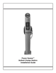
Figure 5. Status Indicators.
Step 1: Ensure that the electrical service wires are landed according
Step 5: If a SAE J1772 Compliant Electric Vehicle is available, please
to this manual. Make sure the station access door is closed
and locked.
connect the EV Connector to the Vehicle Inlet. You may also
use an Eaton Vehicle Simulator, part number "EVSETESTB'.
Step 2: Power ON the Distribution Breaker.
Step 3: During initial EVSE boot-up, the User Interface will cycle all
ICONs.
Step 4: After boot-up, the Power ICON will be STEADY. If this is not
the case, please verify that all incoming service connections
are landed appropriately and that the distribution breaker is
in-tact. If the Power ICON still does not appear, please call
technical support at 1-855-ETN-EVSE (1-855-386-3873).
Step 6: The CHARGING INDICATOR will begin to blink.
Step 7: Almost immediately, the vehicle will engage a charge session (the contactor will close and power will be supplied to
the vehicle).
See Table 9: Normal Operation User Interface Indicators, in
the Appendix, for more details.
Step 8: When power is being supplied to the vehicle, the
CHARGING INDICATOR will move from a BLINK status
to STEADY status signifying that current is flowing to the
vehicle.
Step 9: You may now remove the connector from the vehicle at
your leisure.
EATON www.eaton.com
7
Installation and Service Manual
Fleet AC Level 2 Electric Vehicle
Supply Equipment (EVSE)
Instruction Manual MN191003EN
Effective August 2013
Ground FaultTest
Dip Switch Settings
& CAUTION
MODIFYING THE DIP SWITCH CONFIGURATION OF THE UNIT COULD
CAUSE THE UNIT NOT TO OPERATE AS DESIRED. PLEASE ONLY MODIFY
DIP SWITCH SETIINGS IF YOU ABSOLUTELY UNDERSTAND THE IMPACT
TO THE UNIT.
Figure 6. Ground Fault Test.
The ground fault detection feature is self tested every time the unit
starts a plug session to charge a vehicle. A User can manually test
the ground fault feature at any time by pressing and holding the
Temporary reset Button (right button) for approximately seven seconds. If the test passed successfully, the fault light will flash once.
If it detects a problem, the power icon will turn off and the service
light (wrench icon) will have a medium single blink until power is
cycled to the unit. See Table 10: EVSE Fault or Error User Interface
Indicators, in the Troubleshooting Section in the Appendix, for more
details.
There are two types of Reset, the Temporary Fault Reset and
Service Reset. The Temporary Reset is used when the vehicle
experiences a temporary fault and the user can press the right membrane push button on the interface to reset. This can be performed
5 times before the station will lock out and report a failure. The
Service Reset can be performed when the EVSE as a system needs
to be rebooted and a reset of power is not possible. This can be
performed by simultaneously holding down both membrane push
buttons (labeled in Figure 5 as Override Button and Temporary Reset
Button) on the interface for approximately seven to ten seconds.
Automatic Reset Feature
From the factory, the EVSE is set to automatically reset after a temporary fault. The User has to manually disable the automatic reset
feature if desired.
The EVSE will automatically reset a limit of 5 times before the user
is locked out.
Power Up Delay Feature
There is a "Power Up Delay" that is a random amount of time
between 3 and 8 minutes for units that are plugged into vehicles
after a power outage. This ensures Charging Sessions are started at
different times across your fleet.
8
EATON www.eaton.com
Figure 7. Enabling/Disabling Automatic Reset.
During installation, the Automatic Reset setting can be either left
enabled as it came from the factory, or the User can decide to
disable the feature. To enable or disable this feature, a Service
Technician must change the position of a dip switch on the control
board.
• To Enable Automatic Reset: Dip Switch Block SW2, Position 6
must be ON.
• To Disable Automatic Reset: Dip Switch Block SW2, Position 6
must be OFF.
For board replacements or basic confirmation of settings, Table 3
contains the explanation of the dip switch settings found in the
corner of the Eaton Protection and Control Board (EPCB) near the
RS232 Serial port, labeled SW1 and SW2.
Installation and Service Manual
Fleet AC Level 2 Electric Vehicle
Supply Equipment {EVSE)
Instruction Manual MN191003EN
Effective August 2013
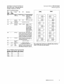
Table 3. Dip Switch Settings.
Dip
Switch
Block
Dip
Switch
Position
SW2
Feature
ON
OFF
Description
Voltage
US 120V
Configuration
US
208/240V
Voltage Configuration
of the Unit. For 120V
Configuration A Wire Jumper is
included between L2
and N
50Hz
North America is 60Hz
SW2
2
Operating
Frequency
SW2
3, 4,
and 5
Reserved for
Factory Use
SW2
6
Auto-reset
after fault
Enabled
Soft Start
Default in OFF position. If ON, the EVSE will
perform a ramp up of current to the Available
Line Current (ALC) or Nameplate Rating over a
30 second time period. This is done through
the SAE J1772 handshake with the vehicle by
modifying the Duty Cycle on the Pilot Signal.
SW2
SW2
8
60Hz
Download
SW1
Reserved for Factory Use.
Disabled
Default in Disabled
position.
A vehicle fault must
be reset manuallythe owner can easily
enable this feature
via this dip switch.
Doing so, will enable
an auto-reclosure on a
nuisance trip
Default in OFF position, Used to install new
firmware updates from the SD Card Slot. For
more details, consult factory.
Reserved for
Factory
Default in OFF position
Defaults in ON position.
See Baud Rate Dip Switch Table 4.
SW1
2 and 3
RS485 Baud
Rate
SW1
4, 5, 6, 7,
and 8
RS485
Address
Defaults in OFF except for Position 8, i.e. Ox01.
Range OxOO to Ox1 Fusing binary addressing
(Most Significant Bit being SW1- Position 4)..
SW1
SW2
CEJ~
I8
BI·"
1(
0
B ILfl
18
IM
IB
IM
[EJ~~]N
[§J
IN
e51
a1~
I-
Ef 1-
~'-----=-----:..:......l.
Figure 8. Dip Switch Settings for a 208/240V, 60Hz, 70A Fleet
Level 2 EVSE with Auto-reset Enabled.
Table 4. RS485 Baud Rate Dip Switch Table
Baud Rate
SW1 - Position 2
SW1 - Position 3
9600
OFF
OFF
ON
19200
OFF
38400
ON
OFF
115200
ON
ON
EATON www.eaton.com
9
Installation and Service Manual
Fleet AC Level 2 Electric Vehicle
Supply Equipment (EVSE)
Instruction Manual MN191003EN
Effective August 2013
Table 7. Physical and Environmental Specifications.
9. Specifications
The Eaton Fleet AC Level 2 EVSE is compliant with the following
standards:
Description
Dimensions - H x W x D
Fleet Level 2
15.5' x 12.26' x 6.52'
(not including the cable hanger or strain relief)
• Society of Automotive Engineers (SAE) J1772™ EV Conductive
Charge Coupler and Station.
Status Indicators
• UL 2231 Personnel Protection Systems for EV Charging Circuits.
Push Buttons
• UL 2594 EV Supply Equipment (Outline of Investigation).
Ingress Protection
• UL 1998 Software in Programmable Components.
Type Rating
• FCC compliant, Part 15.
Temperature - Operating
-30 to 50 degrees Celsius
• Canadian Standard Association (CSA) C22.2.107.1
Temperature - Storage
-40 to 70 degrees Celsius
Humidity
90% RH, non-condensing
6 LEDs: 'Power', 'Charging', 'Complete', 'Remotely
Controlled', Temporary Fault', and 'Service'
2 Buttons: 'Override' and 'Temporary Reset'
IP14
3R
Table 5. Electrical and Mechanical Specifications.
Description
48A
Incoming Voltage
208/240 VAC
Line 1, Line 2, Earth Ground
70A
Input Frequency
50/60Hz
Table 8. 1/0 Specifications.
Description
Fleet Level 2
Same as Output Rating
90 A
J1772™ Pistol Grip EV
Connector
Output Voltage
Same as Incoming
Permissive Run Contact
NC dry contact input
Output Frequency
Same as Incoming
4 - 20mA analog input
70A
Available Line Current
Control
Upstream Breaker Size
60 A
Output Amperage - Max Continuous
Interlocked Power Output
48A
Yes (randomized across a time range to stagger
power up across deployments)
RS-485
Modbus-RTU 4-wire port
Memory
SD Memory Slot
Output Amperage + 5%
Ethernet
Overcurrent Rating
Ground Fault Interruption
Automatic Reset after Nuisance Trip
Feature
20mA
(UL2231-1/UL2231-2 Personnel Protection)
DIP switch selectable Enable/Disable
(default Enabled)
Randomized Restart On Power
Failure (delay before charging
resumes after a power failure)
Mechanica I Operations
Yes
10,000 cycles (EV Connector, replaceable)
100,000 cycles (Contactor, replaceable)
4.4- 5.3 (.5 - .6)
Incoming Modbus Connections
Terminal Block Torque in in-lb (Nm)
Packaged Weight in lb (kg)
45 lbs. (20 kg)
Unpackaged Weight in lb (kg)
40 lbs. (1 Bkg)
Table 6. DP Contactor Wire and Torque
Copper Only (Stranded or Solid)
Wire Guage Range
Torque Rating
14-10 AWG
35 lb-in
BAWG
40 lb-in
6-4AWG
45 lb-in
3-2AWG
50 lb-in
10
EATON www.eaton.com
Field Diagnostics and
Upgrade Port
*Optional
Modbus TCP*
RS-232 DB9 (HyperTerminalTM Support)
Installation and Service Manual
Fleet AC Level 2 Electric Vehicle
Supply Equipment (EVSE)
Instruction Manual MN191003EN
Effective August 2013
Appendix
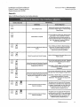
Table 9. EVSE Normal Operation User Interface Indicators
EVSE Meaning
Interface Snap Shot
Definition
Action Re uired
Steady
Unit is Ready for Use
Remove EV Connector from EVSE and Mate to
your Electric Vehicle. Plug-In to Vehicle to Begin
Charge Session
Single
Blink
Authorization is required
Al If the EVSE has a RFID reader, please present
your keyfob or other credential to activate.
Bl Otherwise proceed to process payment via
Credit Card Payment System on the front of the
unit. After payment is rendered, EVSE will
activate and Power ICON
Steady
Single
Blink
Vehicle Connected, EVSE Ready, Waiting on
Vehicle
None - Waiting on Vehicle to Begin Charging. If
vehicle does not begin charging momentarily,
please check internal scheduling system or
remove and re-insert EV Connector
Steady
Steady
Vehicle Connected and Vehicle Charging
Wait for Full Charge or Disconnect When you are
Ready to Leave
Steady
You can now walk away from the unit. Charging
will begin with Building Management System
Allows.
Single
Single
Blink
Vehicle Connected and Charging is Remotely
Controlled by Building Management System Charging Set to INACTIVE
Depending on Facility Setup, Local Override may
be available by pushing the "Override
Pushbutton"
Single
You can now walk away from the unit. Charging
will begin when Vehicle Engages Charge Session.
~
Steady
Vehicle Connected and Charging is Remotely
Controlled by Building Management System Depending on Facility Setup, Local Override may
Charging Set to ACTIVE but at a reduced
be available by pushing the "Override
level.
Pushbutton" This will request to charge at full
capacity.
~
Steady
Steady
Single
Blink
Steady
Steady
Single
Blink
Steady
Vehicle Connected and Current Charge
Session is Complete.
At anytime, you may remove the EV Connector
and Re-Dock it to the EVSE. If the vehicle wants
to engage a charging again at a later time while
you are away, it may do so at anytime. No
additional activity is required by you.
Vehicle Connected and Current Charge
Session is Complete.
At anytime, you may remove the EV Connector
and Re-Dock it to the EVSE. If the vehicle wants
to engage charging again at a later time while
you are away, it may do so at anytime. No
additional activity is required by you.
EATON www.eaton.com
11
Installation and Service Manual
Fleet AC Level 2 Electric Vehicle
Supply Equipment (EVSE}
Instruction Manual MN191003EN
Effective August 2013
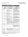
Table 10. EVSE Fault or Error User Interface Indicators
In all Errors/Faults, the
Power ICON will be ON or
Blinking. On a few of the
Errors the Charging ICON
will BLINK to describe the
specific Error.
Will present itself in a blink pattern
or a steady icon. Typically is a
vehicle related concern. Eaton
Will present itself in a
blink pattern or a
steady icon. Typically
an Internal EVSE
defines this as a Temporary Fault or
in rare occurances a Nuiscance Trip.
Concern
Icon Pattern
Recommendation I Action
Fault/Error Desci tion
- Use reset option to Clear Error*.
Steady
Steady
Fast Double
Blink
SAE J1772 Concern
- If AutoReclosure is ENABLED, the EVSE will
Rarely Occurs: Vehicle Nuiscance Trip
auto clear this error after 15 minutes.
- Starting a new Plug Session will also clear
the error. A new Plug Session is defined as
Continually Occurs: Vehicle SAE J1772
Compatibility Concern
Slow Single
Fast Double
Blink
Blink
removing the EV Connector from the Vehicle
Inlet and re-Inserting it Into the Vehicle Inlet.
SAE J1772 Concern
~Use Service Reset or Temporary Fault Reset ..
Rarely Occurs: Vehicle Nuiscance Trip
Continually Occurs: Vehicle SAE J1772
- Starting a new Plug Session will also clear
the error. A new Plug Session is defined as
removing the EV Connector from the Vehicle
Inlet and re-inserting it into the Vehicle Inlet.
Compatibility Concern
Steady
Slow Single
Steady
Blink
Ground Fault Concern
- Use reset option to Clear Error*.
Rarely Occurs: Vehicle Nuiscance Trip
Continually Occurs: Ground/Leakage Current
- Starting a new Plug Session will also clear
the error. A new Plug Session is defined as
removing the EV Connector from the Vehicle
Inlet and re-inserting it into the Vehicle Inlet.
Detection
Vehicle Tried to Pull more Power the the EVSE
8
Use reset option to Clear Error*.
has instructed it to pull.
Steady
0
Steady
Slow Single
Blink
Slow Single
Blink
Rarely Occurs: Vehicle Nuiscance Trip
Continually Occurs: Vehicle SAE J1772
Compatibility Concern
• Starting a new Plug Session will also clear
the error. A new Plug Session is defined as
removing the EV Connector from the Vehicle
Inlet and re-inserting it into the Vehicle Inlet.
Max Temporary Faults for One Plug Session
Medium Blink
Starting a new Plug Session will clear the error.
If this occurs, 5 vehicle related concerns
A new Plug Session is defined as removing the
happened during 1 Plug Session. A Plug Session
EV Connector from the Vehicle Inlet and re·
is defined as the moment the user plugs the EV
inserting it into the Vehicle Inlet.
Connector into his/her vehicle inlet and then
removes it.
Steady
Assymetric
Double Blink
GF Test Failure Prior to Engaging Charge Session Call Technical Support· 1-855-ETN-EVSE
- Ensure that the Incoming Electrical Wires are
Landed according to the Installation Manual.
Steady
Steady
Steady Slow Single Blink
*
Contactor Failure
Steady
Very Fast
Blink
Steady
Asymmetric
Double Blink
The occurance of Vehicle Related Errors have
reached a maxium. The unit is temporarily
disabled so that an investigation can be done.
Call Technical Support - 1·855-ETN·EVSE
Unit is locked out and not operable
Call Technical Support· 1·855-ETN-EVSE
Unit is locked out and not operable
Call Technical Support· 1·855-ETN·EVSE
The user interface will go through a startup mode which initiates a self·check by momentarily testing each
icon before returning to a solid Power Ready LED.
12
- the EVSE Requires an L1, L2, and Ground.
- Please consult the Installation Gulde for
further details.
EATON www.eaton.com
Installation and Service Manual
Fleet AC Level 2 Electric Vehicle
Supply Equipment (EVSE)
Instruction Manual MN191003EN
Effective August 2013
Notes:
Markings:
The physical unit must comply with NEC 625.15 (USA) and CEC
Part 1 Section 86 (Canada).
A. "For use with Electric Vehicles"
B. "Ventilation Not Required"
EATON www.eaton.com
13
Instruction Manual MN191003EN
Installation and Service Manual
Fleet AC Level 2 Electric Vehicle
Supply Equipment (EVSE)
Effective August 2013
For more information,
I u I
l:TN-EVSE (l-855-386-3873),
or call your local Eaton salc-?s office.
Eaton
Electrical Sector
1000 Eaton Boulevard.
Cleveland, OH 44122
United States
877-ETN-CARE (877-386-2273)
Eaton.com
Powering Business Worldwide
© 2013 Eaton
Electrical Sector
All Rights Reserved
Printed in USA
Publication No. MN191003EN /TBG001067
August 2013
Canadian Operations
5050 Mainway
Burlington, ON L7L Canada
Eaton Canada.ca
Eaton is a registered trademark.
All other trademarks are property of their
respective owners.