1
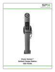
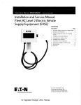
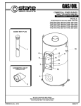
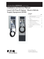
Instruction Manual IM0EV00002E Effective April 2012 Installation and Service Manual Level 2 AC Pow-R-Station™ Electric Vehicle Supply Equipment (EVSE) Contents DescriptionPage 1. Important Safety Instructions- Please Read . . 2 2. Symbols and Definitions. . . . . . . . . . . . . . . . . 2 3. About the Pow-R-Station EV Charging Station. . . . . . . . . . . . . . . . . . . . . . . . . . . . . . . 3 4.Installation. . . . . . . . . . . . . . . . . . . . . . . . . . . . 4 5. Installing the Electrical Service. . . . . . . . . . . . 6 6. Instructions for Opening Door Latch . . . . . . . 7 7. Installing to the Premise. . . . . . . . . . . . . . . . . 8 8. Termination and Configuration. . . . . . . . . . . . 10 9. Confirming Installation and First Use . . . . . . 12 10.Installation Validation for Communications Connectivity. . . . . . . . . . . . . . . . . . . . . . . . . . 14 11.Specifications . . . . . . . . . . . . . . . . . . . . . . . . 17 12Appendix. . . . . . . . . . . . . . . . . . . . . . . . . . . . 18 For more information, visit www.eaton.com/plugin, call 1-855-ETN-EVSE (1-855-386-3873), or call your local Eaton sales office. Instruction Manual IM0EV00002E Effective April 2012 1. Important Safety Instructions - Please Read WARNING ELECTRICAL This equipment should be installed, adjusted, and serviced by qualified electrical personnel familiar with the construction and operation of this type of equipment and the hazards involved. Failure to observe this precaution could result in death or severe injury Installation and Service Manual Level 2 AC Pow-R-Station™ Electric Vehicle Supply Equipment (EVSE) Definitions AC – Alternating Current. The type of power available in most buildings and on utility poles. The Pow-R-Station EVSE protects Users and vehicles by allowing AC power to flow through it to the vehicle. The vehicle then converts the AC to DC (Direct Current) to charge the traction battery. ALC – Available Line Current. The Pow-R-Station EVSE tells the vehicle through the J1772™ connector’s pilot pin how much current (in amperes) it is allowed to pull on the circuit. This allows the car to not exceed the circuit’s maximum current rating. Read this manual thoroughly and make sure you understand the procedures before you attempt to operate this equipment. EVSE – Electric Vehicle Supply Equipment. EVSE is a general term used for all of the equipment used to supply electricity to the car, such as the Eaton Pow-R-Station EVSE. The purpose of this manual is to provide you with information necessary to safely operate, maintain, and troubleshoot this equipment. Keep this manual for future reference. GFCI – Ground Fault Current Interrupter. GFCI protects Users from faults involving leakage currents going to ground, rather than the proper return path of the circuit. Do not use this product if the EV Cable is frayed, has damaged insulation or any other sign of damage. J1772™ – The SAE Recommended Practice for conductive charging of hybrid and electric vehicles. This standard spells out the physical dimensions of the J1772 connector and the pilot communication between the plug-in vehicle and EVSE. Do not use this product if the enclosure or the EV connector is broken, cracked, open, or show any other indication of damage. Intended for use with plug-in electric vehicles only. Premise ventilation not required. The information contained in this manual is subject to change without notice. 2. Symbols and Definitions WARNING ELECTRICAL This symbol indicates high voltage. It calls your attention to items or operations that could be dangerous to you and other persons operating this equipment. Read the message and follow the instructions carefully. WARNING Indicates a potentially hazardous situation which, if not avoided, can result in serious injury or death. caution Indicates a potential hazardous situation which, if not avoided, can result in minor to moderate injury, or serious damage to the equipment. The situation described in the CAUTION may, if not avoided, lead to serious results. Important safety measures are described in CAUTION (as well as WARNING). important Indicates a particular item or instruction this is important to consider. Save These Instructions 2 eaton corporation www.eaton.com Pilot – The signal through the J1772 connector. This signal tells both the vehicle and the EVSE when both are ready to charge and how much current it is allowed to pull. This signal is a SAE standard. Plug Session – The time while the EVSE is plugged into a vehicle. It starts by plugging in the J1772 connector and ends when unplugging the same connector. SAE – Society of Automotive Engineers. The group that organizes and leads committees of transportation experts to create standards, such as J1772, for the transportation industry. Traction Battery – The large battery on a plug-in electric vehicle that is used to store and release energy for propulsion. This is different than the 12V battery that is used to start the vehicle initially and run accessories such as the radio. UI – The User Interface part of the unit. TB – The Terminal Block is where the incoming field power will be terminated in the EVSE unit. ADA – Americans with Disabilities ACT. Installation and Service Manual Level 2 AC Pow-R-Station™ Electric Vehicle Supply Equipment (EVSE) 3. About the Pow-R-Station EV Charging Station Eaton’s Pow-R-Station is Electric Vehicle Supply Equipment (EVSE) and is compatible with the Society of Automotive Engineers J1772™ standard for charging plug-in hybrid and all-electric vehicles. The Pow-R-Station EV Charging Station has several safety features: • Protects Users with interlocked power – the cable and pins have no power on them until the connector is safely plugged into a vehicle • Protects Users from temporary faults – and automatically resets* so no User interaction is needed. • Instructs the vehicle on how much current to draw – keeps the upstream circuit protection from ‘nuisance tripping’. • Allows integration into authorization and management systems – keeping only authorized personnel able to use units and power usage levels to predefined levels. • See section ‘Specifications’ for more details *Automatic Reset feature must be enabled during installation – see page 15 for more information. Moving, Transporting and Storage Instructions Store this unit indoors and in its original packaging until it is ready to be installed. Storage temperature should be between -30° and 80° C. When moving or lifting the unit always grasp the unit enclosure. NEVER attempt to lift, move, or carry the unit by the EV cable. DO NOT carry the unit by the cable hook assembly. Improper storage or handling may cause damage to the unit. Before You Begin WARNING ELECTRICAL WARNING – ONLY QUALIFIED PERSONNEL FAMILIAR WITH THE OPERATION AND CONSTRUCTION OF THIS EQUIPMENT SHOULD INSTALL, ADJUST, MODIFY, AND SERVICE THIS EQUIPMENT. FAILURE TO FOLLOW THE INSTRUCTIONS COULD RESULT IN SEVERE BODILY INJURY OR DEATH. important The user is responsible for conforming to all local and National Electric Code® standards applicable in the environment that the Pow-R-Station is being installed and commissioned. Instruction Manual IM0EV00002E Effective April 2012 ADA Standards for Accessible Design It is very important to consider all STANDARDS FOR ACCESSIBLE DESIGN for Americans with Disabilities when choosing the location and placement of all Electric Vehicle Supply Equipment. The following is a direct excerpt from the 2010 ADA Standards for Accessible Design (http://www.ada.gov/regs2010/2010ADAStandards/2010ADAs tandards.htm#c3) “The Department of Justice published revised regulations for Titles II and III of the Americans with Disabilities Act of 1990 “ADA” in the Federal Register on September 15, 2010. These regulations adopted revised, enforceable accessibility standards called the 2010 ADA Standards for Accessible Design “2010 Standards” or “Standards”. The 2010 Standards set minimum requirements – both scoping and technical -- for newly designed and constructed or altered State and local government facilities, public accommodations, and commercial facilities to be readily accessible to and usable by individuals with disabilities. Adoption of the 2010 Standards also establishes a revised reference point for Title II entities that choose to make structural changes to existing facilities to meet their program accessibility requirements; and it establishes a similar reference for Title III entities undertaking readily achievable barrier removal. The Department has assembled this online version of the official 2010 Standards to increase its ease of use. This version includes: 2010 Standards for State and Local Government Facilities Title II; and 2010 Standards for Public Accommodations and Commercial Facilities Title III. The Department has assembled into a separate publication the revised regulation guidance that applies to the Standards. The Department included guidance in its revised ADA regulations published on September 15, 2010. This guidance provides detailed information about the Department’s adoption of the 2010 Standards including changes to the Standards, the reasoning behind those changes, and responses to public comments received on these topics. The document, Guidance on the 2010 ADA Standards for Accessible Design, can be downloaded from: http://www.ada.gov For information about the ADA, including the revised 2010 ADA regulations, please visit the Department’s website www.ADA.gov; or, for answers to specific questions, call the toll-free ADA Information Line at 800-514-0301 (Voice) or 800-514-0383 (TTY). Replacement Parts List Table 1. Replacement Parts List. Part Part Number Protection and Control Board PCBA 91C5370G01 Cable / Connector Assembly 91C5363G02* Inlet Housing 43-276* Ribbon Cable for User Interface 91C5361G01 User Interface Unit 91C5360G01 Contactor 120V 30A 91C5362G02* Contactor 70A C25FNF37B *consult with your local sales office to confirm availability eaton corporation www.eaton.com 3 Instruction Manual IM0EV00002E Effective April 2012 4. Installation Installation and Service Manual Level 2 AC Pow-R-Station™ Electric Vehicle Supply Equipment (EVSE) In North America, it is recommended to install Pow-R-Station EVSE’s with a high focus on orientating the station toward the front and driver side of parking spaces. Suggestions for different types of parking layouts are illustrated below. Choosing a Location important THings to consider before choosing a location to mount the unit: 1. 2010 Standards for Accessible Design. 2. Consultation with an architect may be needed in order to conform to all governing standards for location and placement of Electric vehicle supply equipment. 3.location of an available mounting support - the wall mount unit must be anchored into a mounting support such as a 2 x 4 stud or solid concrete wall, using mounting hardware that is appropriate for the surface on which you are mounting. Do not mount this unit to a stucco/drywall/wallboard. 4.location of an available electrical source - power wires must be run through an approved conduit or jacket from the circuit panel to the unit. 5.location of the vehicle's charging inlet while parked the unit must be located so its respective cable length is right-sized to where the vehicle's inlet is for plug-in without undue maneuvering. Figure 2. 90 Degree Parking. NNote: These installation location recommendations are based upon general purpose parking, trying to serve the most likely plug-in vehicle drivers. For specific parking, such as at home or in a captive fleet scenario where the User knows where the vehicle’s inlet will be, locate the Pow-R-Station appropriately. Each plug-in electric vehicle manufacturer has a different location for where the charging inlet is located on the vehicle. Figure 3. 45 Degree Parking. Figure 1. Vehicle Inlet Locations Differ by Manufacturer. 4 eaton corporation www.eaton.com Installation and Service Manual Level 2 AC Pow-R-Station™ Electric Vehicle Supply Equipment (EVSE) Instruction Manual IM0EV00002E Effective April 2012 Wheel stops are recommended to be installed at a minimum distance of four feet from the front of the Pow-R-Station EVSE to the vehicle side of the wheel stop for general purpose parking. This distance takes into effect when larger vehicles, like the backing up of a pickup truck with a trailer hitch, back into such a space. For fleet customer with specific vehicles or for parking restricted to plug-in vehicles only, the wheel stop installation distance may be different. Figure 4. Parking Bay/Garage. NNote: The wall-mount style of Pow-R-Station can come with a much longer cord, so in Parking Bays and Garages, length of the cord is less of a problem for maintenance. Protecting the Location For outdoor installations, creative use of protective bollards and wheel stops are necessary. Vehicles can and will damage the units if left unprotected. Figure 6. Protecting the Pow-R-Station EVSE with Bollards (for Reference Only). Protective bollards are recommended to be installed in the area in close proximity of the Pow-R-Station EVSE. See local jurisdiction requirements for actual specifications. Figure 5. Protecting the Pow-R-Station EVSE with Wheel Stops for General Purpose Parking. eaton corporation www.eaton.com 5 Installation and Service Manual Level 2 AC Pow-R-Station™ Electric Vehicle Supply Equipment (EVSE) Instruction Manual IM0EV00002E Effective April 2012 WARNING ELECTRICAL 5. Installing the Electrical Service Checking the Electrical Requirements The National Electric Code®, Article 625.21 states “Overcurrent protection for feeders and branch circuits supplying electric vehicle supply equipment shall be sized for continuous duty and shall have a rating of not less than 125 percent of the maximum load of the electric vehicle supply equipment.” A load study of the location’s electrical service may be needed to determine the availability of adequate electrical service. Take the nameplate amperage rating of the Pow-R-Station, and multiply by 125% for the minimum upstream circuit protection needed. Check your local jurisdictions for any other electrical requirements. WARNING – LOCKOUT/TAGOUT ALL ELECTRICAL SOURCE CIRCUITS FEEDING THE UNIT(S) IN THE OPEN POSITION BEFORE BEGINNING WIRING OR TERMINATIONS. FAILURE TO FOLLOW THE INSTRUCTIONS COULD RESULT IN SEVERE BODILY INJURY OR DEATH. WARNING This unit is rated for indoor or outdoor installation. If this unit is mounted outdoors, the hardware for connecting the conduits to the unit must be rated for outdoor installation and be installed properly to maintain the proper NEMA 3R rating on the unit. Running the Wires Once the proper electrical overcurrent device has been installed, wire needs to be run from it to the Pow-R-Station EVSE. For a typical installation, the only field wires will be for the incoming electrical service. If the EVSE has a Level 1 option, additional service and wiring will be needed. If the EVSE unit has a remote management option, a standard CAT5/6 network cable or 3-wire shielded cable typical for a RS485 type network could also need to be run to the unit. The Pow-R-Station operates on a single-phase service – two hots, and one ground. important Confirm with the local electrical requirements for the gauge, temperature rating, and type of wire material used for the overcurrent rating found below. The chart shows a general recommendation. Table 2. Electrical Wire Chart Style Nameplate Overcurrent Suggested Suggested Suggested Rating Wire Gauge Wire Type Wire Temp Rating SAR_B* 30A 40A 8 AWG Copper 75 degrees C −− THE 30A LEVEL 2 EVSE REQUIRES A DEDICATED 208/240VAC 40A UPSTREAM BREAKER. SAR_C* 70A 90A 4 AWG Copper 75 degrees C −− THE 70A LEVEL 2 EVSE REQUIRES A DEDICATED 208/240VAC 90A UPSTREAM BREAKER. SBR_B* 30A 40A 8 AWG Copper 75 degrees C SBR_C* 70A 90A 4 AWG Copper 75 degrees C NNote: Use Copper Conductors ONLY. IMPORTANT −− OPTIONAL LEVEL 1 OUTLET REQUIRES DEDICATED 120VAC 20A UPSTREAM BREAKER. −− DO NOT USE GFCI BREAKERS. GFCI EXISTS IN EVSE AND ON LEVEL 1 OUTLET. For detail on termination of Level 1 option see page 10. 6 eaton corporation www.eaton.com Wall-mount Pedestal Installation and Service Manual Level 2 AC Pow-R-Station™ Electric Vehicle Supply Equipment (EVSE) Instruction Manual IM0EV00002E Effective April 2012 6. Instructions for Opening Door Latch Step 3. Step 1. Rotate the handle counter-clockwise to release latch as shown in Figure 9. The door should pop open. Facing the charging station, locate the door latch on the right side of the unit as shown in Figure 7. Figure 9. Rotate Handle to Release Latch Figure 7. Door Latch. . Step 2. Insert key into lock and turn counter-clockwise (note: for new installations the key will come already in the lock). Once unlocked, the latch should pop outwards as shown in Figure 8. Figure 8. Unlocked Door Latch. eaton corporation www.eaton.com 7 Instruction Manual IM0EV00002E Effective April 2012 Installation and Service Manual Level 2 AC Pow-R-Station™ Electric Vehicle Supply Equipment (EVSE) 7. Installing to the Premise The three typical installation methods of installing Pow-R-Station EVSE’s to the premise are found below. Some installations require installing the wall-mount style of Pow-R-Station EVSE to a wall or unistrut. Mounting to a Wall Preparing the Site Once a proper site has been chosen and the electrical service has been run to the location, you can begin installation. caution DO NOT MOUNT UNIT TO ONLY STUCCO/DRYWALL/WALLBOARD. DO NOT USE TOGGLE BOLTS, ZIP ANCHORS, NOR PLASTIC WALL ANCHORS MEANT FOR THESE MATERIALS BECAUSE THEY DO NOT HAVE THE STRENGTH NEEDED TO SUPPORT THE UNIT. THE UNIT MUST BE MOUNTED TO A SOLID SUPPORT SUCH AS: WOOD, CONCRETE WALL, CONCRETE BLOCK WALL, OR EQUIVALENT. Step 1: Remove the mounting plate from the back of the EVSE unit by placing the unit on a solid non-scratch surface and opening the unit by turning the latch on the side. Remove the three nuts on the 10-32 studs that attach the mounting plate to the unit. The location of these mounting studs can be seen in Figure 10. Save these nuts and washers as they will be needed to re-attach the unit later in the installation. Step 2: Using the mounting plate as a template, mark the holes to be used for mounting. Make sure the mounting plate is level. If mounting on a wood stud wall use the two center holes. If mounting on a solid wall such as concrete, brick, or concrete block, use the four outside square holes. Step 3: Pre-drill mounting holes if mounting into a wood stud or drill appropriate sized holes in a solid wall for use with the type of anchor you will be using. Step 4: Attach mounting plate to the wall as shown in Figure 11. If installing on a wood stud, use 5/16” or 3/8” x 3” long Lag screws and washers. These should be galvanized or stainless steel for weather protection if mounting outdoors. If mounting onto a concrete, block, or brick wall, use an appropriate anchor for the type of wall on which you are installing the unit. Again, these should be appropriate for weather conditions if mounting outside. Figure 11. Typical Wall Mounting. Figure 10. Unit and Mounting Plate. 8 eaton corporation www.eaton.com Step 5: After the mounting plate is secure to the wall, mount the EVSE unit to the mounting plate using the washers and nuts removed in Step 1. Installation and Service Manual Level 2 AC Pow-R-Station™ Electric Vehicle Supply Equipment (EVSE) Mounting to Uni-Strut Once a proper site has been chosen and the electrical service has been run to the location, you can begin installation. Step 1: Remove the mounting plate from the back of the EVSE unit by placing the unit on a solid non-scratch surface and opening the unit by turning the latch on the side (for details, see Section 6. Instructions for Opening Door Latch). Remove the three nuts on the 10-32 studs that attach the mounting plate to the unit. The location of these mounting studs can be seen in Figure 10. Save these nuts and washers as they will be needed to re-attach the unit later in the installation. Step 2: Using the mounting plate as a template, determine where the anchors should be placed to be used for mounting. It Instruction Manual IM0EV00002E Effective April 2012 is recommended in high wind and use area, cross-arms should be used to avoid twisting which can occur in a single pole installation. Make sure the mounting plate is level. If mounting on a single pole use the two center holes. If mounting utilizing cross-arms use the four outside square holes. Step 3: Attach mounting plate using as shown in Figure 12. Use appropriate hardware making sure it is galvanized or stainless steel for weather protection if mounting outdoors. Step 4:After the mounting plate is securely attached to the mounting structure, mount the EVSE unit to the mounting plate using the washers and nuts removed in Step 1. Figure 12. Typical Unistrut Mounting. Figure 13. Dimensional Detail for Unistrut Mounting. eaton corporation www.eaton.com 9 Instruction Manual IM0EV00002E Effective April 2012 Installation and Service Manual Level 2 AC Pow-R-Station™ Electric Vehicle Supply Equipment (EVSE) Figure 14. Base Detail Pedestal for EVSE. Pedestal Floor Mounting 8. Termination and Configuration Preparing the Site Once a proper site has been chosen and the electrical service has been run to the location, you can begin installation. Step 1: Open door using the latch on the side of the unit (see Section 6. Instructions for Opening Door Latch, for details). Step 2: Remove the bottom pan by pulling upward and then angling outward. Best if performed when door is held opened. Step 3: The hole pattern for the base of the pedestal mount is shown below in Figure 14. Use six, 3/8 UNC Grade 5 stainless bolts torqued at 50 ft-lbs for mounting base to the ground. NNote: If using a concrete pad, please be mindful of the overall height of the unit due to ADA Compliance. Please reference the ADA Compliance section of this document. WARNING ELECTRICAL WARNING – LOCKOUT/TAGOUT ALL ELECTRICAL SOURCE CIRCUITS FEEDING THE UNIT(S) IN THE OPEN POSITION BEFORE BEGINNING WIRING OR TERMINATIONS. FAILURE TO FOLLOW THE INSTRUCTIONS COULD RESULT IN SEVERE BODILY INJURY OR DEATH. WARNING – ONLY QUALIFIED PERSONNEL FAMILIAR WITH THE OPERATION AND CONSTRUCTION OF THIS EQUIPMENT SHOULD INSTALL, ADJUST, MODIFY, AND SERVICE THIS EQUIPMENT. FAILURE TO FOLLOW THE INSTRUCTIONS COULD RESULT IN SEVERE BODILY INJURY OR DEATH. Wire Terminations For a typical installation, the only field wire terminations will be the incoming electrical service wires. If the EVSE unit is configured for Pow-R-Station Network Manager or other remote management solution, a standard CAT5/6 network cable or 3-wire shielded cable for RS-485 Communications. Electrical Service Wires Terminate the incoming electrical service wires to the Pow-R-Station EVSE’s provided terminal block, following the designations for each wire. L1, L2, and G (see Figure 15). 10 eaton corporation www.eaton.com Installation and Service Manual Level 2 AC Pow-R-Station™ Electric Vehicle Supply Equipment (EVSE) Instruction Manual IM0EV00002E Effective April 2012 Figure 15. Electrical Service Wiring. NNote: Torque for incoming field service wiring – 22.1 - 26.6 in-lb (2.5 – 3.0 Nm) – Use Copper Conductors Only. Grounding Instructions This product must be connected to a grounded, metal, permanent wiring system; or an equipment-grounding conductor must be run with the circuit conductors and connected to the equipment grounding terminal. Optional Level 1 - 120VAC Outlet When the EVSE is equipped with a Level 1 - 120VAC Outlet perform the wiring instructions outlined below in Figure 16. Level 1 Field Connection Diagram GFCI Receptacle Figure 17. GFCI Receptacle Location - Reference Only Control Wires RJ45 CAT5/6 network cable or a 4-wire shielded Belden cable for Modbus communication may be needed based upon the configuration of your Pow-R-Station. Terminate these wires before applying the electrical service wires. If none present, skip this step and go to the next section. Figure 16. Optional Level 1 - 120VAC Outlet Figure 18. Control Wiring. eaton corporation www.eaton.com 11 Instruction Manual IM0EV00002E Effective April 2012 Installation and Service Manual Level 2 AC Pow-R-Station™ Electric Vehicle Supply Equipment (EVSE) 9. Confirming Installation and First Use Figure 19. Status Indicators. Step 1: Ensure that the electrical service wires are landed according to this manual. Make sure the station access door is closed. Step 2: Power ON the Distribution Breaker. Step 3: During initial EVSE boot-up, the User Interface will cycle all ICONs. Step 4: After boot-up, the Power ICON will be either STEADY or BLINKING per above table. If this is not the case, please verify that all incoming service connections are landed appropriately and that the distribution breaker is in-tact. If the Power ICON still does not appear, please call technical support. 12 eaton corporation www.eaton.com Step 5: If the Power ICON is BLINKING, Authorization is needed. Please consult the Authorization section of this document below. If the Power ICON is STEADY, please proceed to the next step. Step 6: If a SAE J1772 Compliant Electric Vehicle is available, please connect the EV Connector to the Vehicle Inlet. You may also use an Eaton Vehicle Simulator. Step 7: The CHARGING INDICATOR will begin to blink. Step 8: Almost immediately, the vehicle will engage a charge session (the contactor will close and power will be supplied to the vehicle). See Table 10: Normal Operation User Interface Indicators, in the Appendix, for more details. Installation and Service Manual Level 2 AC Pow-R-Station™ Electric Vehicle Supply Equipment (EVSE) Step 9: When power is being supplied to the vehicle, the CHARGING INDICATOR will move from a BLINK status to STEADY status signifying that current is flowing to the vehicle. Step 10: You may now remove the connector from the vehicle at your leisure. Authorization Needed: If Authorization is needed, the Power ICON will have a BLINK pattern. This signifies to the end User that either payment activation is needed or RFID authorization. Ground Fault Test Figure 20. Ground Fault Test. The ground fault detection feature is self tested every time the unit starts a plug session to charge a vehicle. A User can manually test the ground fault feature at any time by pressing and holding the reset button (right button) for seven seconds. If the test passed successfully, the fault light will flash once. If it detects a problem, the power icon will turn off and the service light (wrench icon) will have a medium single blink until power is cycled to the unit. See Table 11: EVSE Fault or Error User Interface Indicators, in the Troubleshooting Section in the Appendix, for more details. Instruction Manual IM0EV00002E Effective April 2012 • To Enable Automatic Reset: Dip Switch Block SW2, Position 6 must be ON. • To Disable Automatic Reset: Dip Switch Block SW2, Position 6 must be OFF. For board replacements or basic confirmation of settings, Table 3 contains the explanation of the dip switch settings found in the corner of the Eaton Protection and Control Board (EPCB) near the RS232 Serial port, labeled SW1 and SW2. Table 3. Dip Switch Settings. Dip Switch Block Dip Switch Position Feature SW2 1 SW2 ON OFF Description Voltage US 120V Configuration US 208/240V Voltage Configuration of the Unit. For 120V Configuration – A Wire Jumper needs to be added between L2 and N on Figure 15 of this Document. 2 Operating Frequency 50Hz North America is 60Hz SW2 3, 4, and 5 Reserved for Factory Use SW2 6 Auto-reset after fault Enabled SW2 7 Soft Start Default in OFF Position. If ON, the EVSE will perform a ramp up of current to the Available Line Current (ALC) or Nameplate Rating over a 30 second time period. This is done through the SAE J1772 handshake with the vehicle by modifying the Duty Cycle on the Pilot Signal. SW2 8 Reserved for Factory Default in OFF position SW1 1 Reserved for Factory Default in OFF position SW1 2 and 3 RS485 Baud Rate See Baud Rate Dip Switch Table – Default is all ON SW1 4, 5, 6, 7, and 8 RS485 Address 60Hz Dip Switch Settings caution Modifying the DIP Switch Configuration of the Unit could cause the unit not to operate as desired. Please only modify dip switch settings if you absolutely understand the impact to the unit. Automatic Reset Feature From the manufacturer, the Pow-R-Station is set to require a manual reset after a temporary fault. The User has to opt-in to enable the automatic reset feature. Reserved for Factory Use. Disabled Comes from the factory disabled. A vehicle fault must be reset manually – the owner can easily enable this feature via this dip switch. Doing so, will enable an auto-reclosure on a nuisance trip Range 0x00 to 0x1F using binary addressing (Most Significant Bit being SW1- Position 4). Default is all OFF except Position 8, i.e. 0x01. Table 4. RS485 Baud Rate Dip Switch Table. Baud Rate SW1 – Position 2 SW1 – Position 3 9600 OFF OFF 19200 OFF ON 38400 ON OFF 115200 ON ON Figure 21. Enabling/Disabling Automatic Reset. During installation, the Automatic Reset setting can be either left disabled as it came from the factory, or the User can decide to enable the feature. To enable or disable this feature, a Service Technician must change the position of a dip switch on the control board. eaton corporation www.eaton.com 13 Installation and Service Manual Level 2 AC Pow-R-Station™ Electric Vehicle Supply Equipment (EVSE) Instruction Manual IM0EV00002E Effective April 2012 SW1 Communications to Network Manager 7 7 6 4 3 2 ON 1 4 2 1 3 5 5 6 8 8 SW2 ON 10. Installation Validation for Communications Connectivity Figure 22. Dip Switch Settings for a 208/240V, 60Hz, 30A Pow-RStation with Auto-reset DISABLED. There are several communication options to enable connectivity to Network Manager available for Pow-R-Station EVSE. The following instructions detail the validation procedures for confirming connectivity for cellular, Wi-Fi, and Ethernet communication options. Please note that in order for the unit to connect to Network Manager via Wi-Fi and Ethernet connections, the local area network must have access to the following two web addresses: • Address 1: endpoint.gridpoint.com • Address 2: ems.gridpoint.com Please confirm access to these sites with the facility’s IT department. Ethernet Connectivity If the EVSE is setup to connect via hardwired Ethernet over Cat5/6e cable: Step 1 Verify the network providing the Ethernet service to the EVSE has DHCP enabled or if there are any firewalls on the Ethernet drop. Ask facility’s IT if you are not sure. Ensure firewalls will not prevent the Network Manager Controller from connecting to gridpoint.com. Step 2 Disconnect the Ethernet Cable from the Network Manager Controller (See Figure 23). Figure 23. Disconnecting Ethernet cable from Network Manager Controller. 14 eaton corporation www.eaton.com Installation and Service Manual Level 2 AC Pow-R-Station™ Electric Vehicle Supply Equipment (EVSE) Instruction Manual IM0EV00002E Effective April 2012 Step 3 Step 4 Use an RJ45 coupler to connect the Ethernet cable that was just disconnected from the Network Manager Controller to an RJ45 cable and PC as shown in Figure 24. Setup your PC to obtain an IP address automatically. PC RJ45 Cable RJ45 Coupler RJ45 Cable to Network Figure 24. Ethernet cable connected to RJ45 cable and PC. a.On test PC running Windows XP navigate to Start > Control Panel > Network Connections and double click on the Local Area Connection icon. This will open the connection status window for that Ethernet connection. b.Note: Local Area Connection may be a different name depending on how your Ethernet port is setup or if there are multiple Ethernet ports on the test PC. Make sure the next steps are done on the Ethernet port that the modem is connected to on the test PC. c.Go to Properties in the General tab. This will open the Connection Properties window. See Figure 25. d.Double click on the Internet Protocol (TCP/IP) selection. See Figure 25. e.Make sure the “Obtain an IP address automatically” is selected. See Figure 25. Figure 25. PC setup. eaton corporation www.eaton.com 15 Installation and Service Manual Level 2 AC Pow-R-Station™ Electric Vehicle Supply Equipment (EVSE) Instruction Manual IM0EV00002E Effective April 2012 f. Hit Ok for the two windows to close them. Cellular Connectivity g.In the Local Area Connection Status, go to the support tab and verify that an IP address has been assigned. Jot down the Default Gateway address for the Wifi Troubleshooting portion. Step 1 NNote: It does not need to match exact numbers in Figure 26. Please safely energize the unit. The Ethernet Port LED Lights on the Network Manager Controller should now be lit. Step 2: After approximately two minutes, verify that the LED indicator lights on the Cellular Modem are lit according to the following pattern: • Power: Solid • Network: Solid • Signal: • Solid (very strong) • Fast Blink (strong) • Normal Blink (good) • Slow Blink (weak) • None (no signal) Figure 27. Cellular Model LED Indicator Lights. Step 3: To verify connectivity, call GridPoint technical support at 1-866-800and provide them with the Network Manager controller serial number. For more information about setting up connectivity to Network Manager, see the Network Manager quick start guide (document IL0EV00006E). Wi-Fi Connectivity Figure 26. Support tab of Local Area Connection Status. Step 5 Once an IP address is assigned to the PC, open an internet browser and go to a website like gridpoint.com. If the Ethernet service is open it should allow for any popular website to be accessed. Step 6 If you are able to access a website, then you have verified that the Ethernet service for the Network Manager Controller is properly functioning. For more information about confirming Ethernet connectivity contact Eaton Tech Support at 1-855-ETN-EVSE (386-3873) 16 eaton corporation www.eaton.com Please refer to Instructional Leaflet IL0EV00008E (Level 2 AC PowR-Station electric vehicle supply equipment Wi-Fi configuration quick start guide) to confirm Wi-Fi connectivity. Installation and Service Manual Level 2 AC Pow-R-Station™ Electric Vehicle Supply Equipment (EVSE) 11. Specifications Instruction Manual IM0EV00002E Effective April 2012 Table 6. Physical and Environmental Specifications. The Eaton Pow-R-Station EVSE is compliant with the following standards: Description Dimensions - H x W x D Wall-mount Pedestal 22” x 15” x 8” (Add 9” below for cable hanger) 52.50” x 15” x 8” • Society of Automotive Engineers (SAE) J1772™ 2010 EV Conductive Charge Coupler and Station. • NFPA 70 National Electric Code, Article 625 Electric Vehicle Charging System. • UL 2231 Personnel Protection Systems for EV Charging Circuits. Ingress Protection • UL 2594 EV Supply Equipment (Outline of Investigation). Type Rating • UL 1998 Software in Programmable Components. Temperature – Operating -30 to 50 degrees Celsius • FCC compliant, Part 15. Temperature – Storage -40 to 70 degrees Celsius Humidity 90% RH, non-condensing Status Indicators 6 LEDs: ‘Power’, ‘Charging’, ‘Complete’, ‘Remotely Controlled’, ‘Temporary Fault’, and ‘Service’ Push Buttons 2 Buttons: ‘Override’ and ‘Reset’ IP14 3R Table 5. Electrical and Mechanical Specifications. Description 30A 70A Incoming Voltage 208 VAC 240 VAC 120 VAC 208 - 240 VAC Description Input Frequency 50/60Hz 50/60Hz Incoming Amperage 40 A 90 A Output Voltage Same as Incoming Output Frequency Table 7. I/O Specifications. Same as Incoming Wall-mount J1772™ Pistol Grip EV Connector Pedestal Same as Output Rating Permissive Run Contact NC dry contact input Available Line Current Control 4 – 20mA analog input Output Amperage - Max Continuous 30A 70A RS-485 Interlocked Power Output Yes Yes Memory SD Memory Slot Ethernet RJ45, IEEE 802.3, TCP/IP, Modbus TCP Overcurrent Rating Ground Fault Interruption Output Amperage + 5% 20mA (UL2231-1/UL2231-2 Personnel Protection) Automatic Reset after Nuisance Trip Feature DIP switch selectable Enable/Disable (default Enabled) Randomized Restart On Power Failure (delay before charging resumes after a power failure) Yes Mechanical Operations 10,000 cycles (EV Connector, replaceable) 100,000 cycles (Contactor, replaceable) Incoming Field Electrical Service Terminal Block Torque in in-lb (Nm) 22.1 – 26.6 (2.5 – 3) Incoming Modbus Connections Terminal Block Torque in in-lb (Nm) 4.4 – 5.3 (.5 - .6) Modbus-RTU 4-wire port Field Diagnostics and Upgrade Port RS-232 DB9 (HyperTerminalTM Support) Table 8. Optional Specifications. Description Through-feed (Daisy Chain) Compatible Network controller Wall-mount Pedestal No Yes Enables connectivity to Pow-R-Station Network Manager with real-time status and historical information Wireless Wi-Fi (WPA or WPA2) RFID basic Basic lock/unlock with card or keyfob RFID User Customer provided third-party database of users integrated for authentication Cellular GPRS/GSM Credit Card Processing PCI-DSS Network Management Pow-R-Station Network Management Solution with Real-time Status and Historical Information Table 9. Optional Level 1 120VAC 20A Outlet . Incoming Voltage 120VAC Input Frequency 60 Hz Output Voltage Same as incoming Output Frequency Same as incoming Output Amperage - Max Continuous 20A eaton corporation www.eaton.com 17 Installation and Service Manual Level 2 AC Pow-R-Station™ Electric Vehicle Supply Equipment (EVSE) Instruction Manual IM0EV00002E Effective April 2012 Appendix Table 10. EVSE Normal Operation User Interface Indicators EVSE Normal Operation User Interface Indicators EVSE Meaning Interface Snap Shot Steady Single Blink Action Required Unit is Ready for Use Remove EV Connector from EVSE and Mate to your Electric Vehicle. Plug-In to Vehicle to Begin Charge Session Authorization is required A) If the EVSE has a RFID reader, please present your keyfob or other credential to activate. B) Otherwise proceed to process payment via Credit Card Payment System on the front of the unit. After payment is rendered, EVSE will activate and Power ICON Steady Single Blink Vehicle Connected, EVSE Ready, Waiting on Vehicle None - Waiting on Vehicle to Begin Charging. If vehicle does not begin charging momentarily, please check internal scheduling system or remove and re-insert EV Connector Steady Steady Vehicle Connected and Vehicle Charging Wait for Full Charge or Disconnect When you are Ready to Leave Steady You can now walk away from the unit. Charging will begin with Building Management System Allows. Vehicle Connected and Charging is Remotely Controlled by Building Management System Charging Set to INACTIVE Depending on Facility Setup, Local Override may be available by pushing the "Override Pushbutton" Single Blink Single Blink Steady You can now walk away from the unit. Charging will begin when Vehicle Engages Charge Session. Vehicle Connected and Charging is Remotely Controlled by Building Management System Depending on Facility Setup, Local Override may Charging Set to ACTIVE but at a reduced be available by pushing the "Override level. Pushbutton" This will request to charge at full capacity. Single Blink Steady 18 Definition Steady Single Blink Steady Steady Single Blink Steady Vehicle Connected and Current Charge Session is Complete. At anytime, you may remove the EV Connector and Re-Dock it to the EVSE. If the vehicle wants to engage a charging again at a later time while you are away, it may do so at anytime. No additional activity is required by you. Vehicle Connected and Current Charge Session is Complete. At anytime, you may remove the EV Connector and Re-Dock it to the EVSE. If the vehicle wants to engage charging again at a later time while you are away, it may do so at anytime. No additional activity is required by you. eaton corporation www.eaton.com Installation and Service Manual Level 2 AC Pow-R-Station™ Electric Vehicle Supply Equipment (EVSE) Instruction Manual IM0EV00002E Effective April 2012 Table 11. EVSE Fault or Error User Interface Indicators EVSE Fault or Error User Interface Indicators Will present itself in a blink pattern or a steady icon. Typically an internal EVSE Concern Icon Pattern Will present itself in a blink pattern or a steady icon. Typically is a vehicle related concern. Eaton defines this as a Temporary Fault or in rare occurances a Nuiscance Trip. Fault/Error Desciption SAE J1772 Concern Steady Fast Double Blink Rarely Occurs: Vehicle Nuiscance Trip Continually Occurs: Vehicle SAE J1772 Compatibility Concern In all Errors/Faults, the Power ICON will be ON or Blinking. On a few of the Errors the Charging ICON will BLINK to describe the specific Error. Recommendation / Action - Press Manual Reset Pushbutton to Clear Error. - If AutoReclosure is ENABLED, the EVSE will auto clear this error after 15 minutes. - Starting a new Plug Session will also clear the error. A new Plug Session is defined as removing the EV Connector from the Vehicle Inlet and re-inserting it into the Vehicle Inlet. - Press Manual Reset Pushbutton to Clear Error. SAE J1772 Concern Steady Slow Single Blink Fast Double Blink Rarely Occurs: Vehicle Nuiscance Trip Continually Occurs: Vehicle SAE J1772 Compatibility Concern - Starting a new Plug Session will also clear the error. A new Plug Session is defined as removing the EV Connector from the Vehicle Inlet and re-inserting it into the Vehicle Inlet. - Press Manual Reset Pushbutton to Clear Error. Ground Fault Concern Steady Slow Single Blink Steady Rarely Occurs: Vehicle Nuiscance Trip Continually Occurs: Ground/Leakage Current Detection Vehicle Tried to Pull more Power the the EVSE has instructed it to pull. Steady Slow Single Blink Slow Single Blink Rarely Occurs: Vehicle Nuiscance Trip Continually Occurs: Vehicle SAE J1772 Compatibility Concern - Starting a new Plug Session will also clear the error. A new Plug Session is defined as removing the EV Connector from the Vehicle Inlet and re-inserting it into the Vehicle Inlet. - Press Manual Reset Pushbutton to Clear Error. - Starting a new Plug Session will also clear the error. A new Plug Session is defined as removing the EV Connector from the Vehicle Inlet and re-inserting it into the Vehicle Inlet. Max Temporary Faults for One Plug Session Steady Medium Blink Steady Assymetric Double Blink Steady Steady Steady Slow Single Blink Starting a new Plug Session will clear the error. If this occurs, 5 vehicle related concerns A new Plug Session is defined as removing the happened during 1 Plug Session. A Plug Session EV Connector from the Vehicle Inlet and reis defined as the moment the user plugs the EV inserting it into the Vehicle Inlet. Connector into his/her vehicle inlet and then removes it. GF Test Failure Prior to Engaging Charge Session Call Technical Support - 1-855-ETN-EVSE Contactor Failure The occurance of Vehicle Related Errors have reached a maxium. The unit is temporarily disabled so that an investigation can be done. - Ensure that the Incoming Electrical Wires are Landed according to the Installation Manual. - the EVSE Requires an L1, L2, and Ground. - Please consult the Installation Guide for further details. Call Technical Support - 1-855-ETN-EVSE Steady Very Fast Blink Unit is locked out and not operable Call Technical Support - 1-855-ETN-EVSE Steady Asymmetric Double Blink Unit is locked out and not operable Call Technical Support - 1-855-ETN-EVSE eaton corporation www.eaton.com 19 Instruction Manual IM0EV00002E Effective April 2012 Installation and Service Manual Level 2 AC Pow-R-Station™ Electric Vehicle Supply Equipment (EVSE) Eaton Corporation Electrical Sector 1111 Superior Ave. Cleveland, OH 44114 United States 877-ETN-CARE (877-386-2273) Eaton.com © 2012 Eaton Corporation All Rights Reserved Printed in USA Publication No. IM0EV00002E / TBG000585 April 2012 Eaton is a registered trademark of Eaton Corporation. All other trademarks are property of their respective owners.