1
HiPath Cordless IP
Service Documentation
A31003-C1010-S100-7-7620
Our Quality and Environmental Management Systems are
implemented according to the requirements of the ISO9001 and
ISO14001 standards and are certified by an external certification
company.
Copyright © Unify GmbH & Co. KG 05/2014
Hofmannstr. 51, 81379 Munich/Germany
All rights reserved.
Reference No.: A31003-C1010-S100-7-7620
The information provided in this document contains merely general descriptions or
characteristics of performance which in case of actual use do not always apply as
described or which may change as a result of further development of the products.
An obligation to provide the respective characteristics shall only exist if expressly agreed in
the terms of contract.
Availability and technical specifications are subject to change without notice.
Unify, OpenScape, OpenStage and HiPath are registered trademarks of Unify GmbH & Co. KG.
All other company, brand, product and service names are trademarks or registered trademarks
of their respective holders.
unify.com
bkTOC.fm
Nur für den internen Gebrauch
Contents
Contents
0
1 Introduction and Important Notes . . . . . . . . . . . . . . . . . . . . . . . . . . . . . . . . . . . . . . . . . . . . . . . . . . . . . . . . . 6
1.1 Safety Information and Warnings. . . . . . . . . . . . . . . . . . . . . . . . . . . . . . . . . . . . . . . . . . . . . . . . . . . . . . . . . . 6
1.2 Correct Use . . . . . . . . . . . . . . . . . . . . . . . . . . . . . . . . . . . . . . . . . . . . . . . . . . . . . . . . . . . . . . . . . . . . . . . . . . 8
1.3 Proper disposal and recycling . . . . . . . . . . . . . . . . . . . . . . . . . . . . . . . . . . . . . . . . . . . . . . . . . . . . . . . . . . . . 9
1.4 Standards and Guidelines on Installation. . . . . . . . . . . . . . . . . . . . . . . . . . . . . . . . . . . . . . . . . . . . . . . . . . . 10
1.4.1 Labeling . . . . . . . . . . . . . . . . . . . . . . . . . . . . . . . . . . . . . . . . . . . . . . . . . . . . . . . . . . . . . . . . . . . . . . . . 10
1.5 Data Protection and Data Security. . . . . . . . . . . . . . . . . . . . . . . . . . . . . . . . . . . . . . . . . . . . . . . . . . . . . . . . 11
1.6 Documentation Feedback . . . . . . . . . . . . . . . . . . . . . . . . . . . . . . . . . . . . . . . . . . . . . . . . . . . . . . . . . . . . . . 12
2 Overview . . . . . . . . . . . . . . . . . . . . . . . . . . . . . . . . . . . . . . . . . . . . . . . . . . . . . . . . . . . . . . . . . . . . . . . . . . . .
2.1 Introduction . . . . . . . . . . . . . . . . . . . . . . . . . . . . . . . . . . . . . . . . . . . . . . . . . . . . . . . . . . . . . . . . . . . . . . . . .
2.1.1 DECT IP Base Station (BSIP1). . . . . . . . . . . . . . . . . . . . . . . . . . . . . . . . . . . . . . . . . . . . . . . . . . . . . . .
2.1.2 HiPath Cordless IP SW. . . . . . . . . . . . . . . . . . . . . . . . . . . . . . . . . . . . . . . . . . . . . . . . . . . . . . . . . . . . .
2.1.2.1 Communication Interfaces. . . . . . . . . . . . . . . . . . . . . . . . . . . . . . . . . . . . . . . . . . . . . . . . . . . . . . .
2.2 System Configuration. . . . . . . . . . . . . . . . . . . . . . . . . . . . . . . . . . . . . . . . . . . . . . . . . . . . . . . . . . . . . . . . . .
2.2.1 Small Solution . . . . . . . . . . . . . . . . . . . . . . . . . . . . . . . . . . . . . . . . . . . . . . . . . . . . . . . . . . . . . . . . . . . .
2.2.2 Server Solution . . . . . . . . . . . . . . . . . . . . . . . . . . . . . . . . . . . . . . . . . . . . . . . . . . . . . . . . . . . . . . . . . . .
2.2.3 Large Solution. . . . . . . . . . . . . . . . . . . . . . . . . . . . . . . . . . . . . . . . . . . . . . . . . . . . . . . . . . . . . . . . . . . .
2.3 DECT IP Base Station Data . . . . . . . . . . . . . . . . . . . . . . . . . . . . . . . . . . . . . . . . . . . . . . . . . . . . . . . . . . . . .
2.3.1 Outdoor Case . . . . . . . . . . . . . . . . . . . . . . . . . . . . . . . . . . . . . . . . . . . . . . . . . . . . . . . . . . . . . . . . . . .
2.3.2 Powering the DECT IP Base Stations . . . . . . . . . . . . . . . . . . . . . . . . . . . . . . . . . . . . . . . . . . . . . . . . .
2.4 Network Requirement . . . . . . . . . . . . . . . . . . . . . . . . . . . . . . . . . . . . . . . . . . . . . . . . . . . . . . . . . . . . . . . . .
2.5 Software License Management . . . . . . . . . . . . . . . . . . . . . . . . . . . . . . . . . . . . . . . . . . . . . . . . . . . . . . . . . .
13
15
15
15
19
21
22
23
24
26
27
28
29
30
3 Planning a HiPath Cordless IP System . . . . . . . . . . . . . . . . . . . . . . . . . . . . . . . . . . . . . . . . . . . . . . . . . . . .
3.1 Planning According to Call Traffic Load . . . . . . . . . . . . . . . . . . . . . . . . . . . . . . . . . . . . . . . . . . . . . . . . . . . .
3.2 General . . . . . . . . . . . . . . . . . . . . . . . . . . . . . . . . . . . . . . . . . . . . . . . . . . . . . . . . . . . . . . . . . . . . . . . . . . . .
3.3 Propagation Conditions for Radio Traffic . . . . . . . . . . . . . . . . . . . . . . . . . . . . . . . . . . . . . . . . . . . . . . . . . . .
3.3.1 In the Open with Visibility . . . . . . . . . . . . . . . . . . . . . . . . . . . . . . . . . . . . . . . . . . . . . . . . . . . . . . . . . . .
3.3.2 Industrial Sites . . . . . . . . . . . . . . . . . . . . . . . . . . . . . . . . . . . . . . . . . . . . . . . . . . . . . . . . . . . . . . . . . . .
3.3.3 Indoor Areas in Buildings in Brick and Light Construction Materials . . . . . . . . . . . . . . . . . . . . . . . . . .
3.3.4 Indoor Areas in Reinforced Concrete Buildings with Diverse Interior Layout . . . . . . . . . . . . . . . . . . . .
3.4 Determining the Installation Site . . . . . . . . . . . . . . . . . . . . . . . . . . . . . . . . . . . . . . . . . . . . . . . . . . . . . . . . .
3.4.1 Indoors . . . . . . . . . . . . . . . . . . . . . . . . . . . . . . . . . . . . . . . . . . . . . . . . . . . . . . . . . . . . . . . . . . . . . . . . .
3.4.1.1 In Buildings of Brick or Light Construction Materials . . . . . . . . . . . . . . . . . . . . . . . . . . . . . . . . . . .
3.4.1.2 In Steel/Concrete Buildings . . . . . . . . . . . . . . . . . . . . . . . . . . . . . . . . . . . . . . . . . . . . . . . . . . . . . .
3.4.1.3 Factory Halls and Open-Plan Offices . . . . . . . . . . . . . . . . . . . . . . . . . . . . . . . . . . . . . . . . . . . . . .
3.4.2 Outdoors . . . . . . . . . . . . . . . . . . . . . . . . . . . . . . . . . . . . . . . . . . . . . . . . . . . . . . . . . . . . . . . . . . . . . . . .
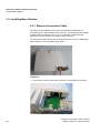
3.5 Installing Base Stations . . . . . . . . . . . . . . . . . . . . . . . . . . . . . . . . . . . . . . . . . . . . . . . . . . . . . . . . . . . . . . . .
3.5.1 Ethernet Connection Cable. . . . . . . . . . . . . . . . . . . . . . . . . . . . . . . . . . . . . . . . . . . . . . . . . . . . . . . . . .
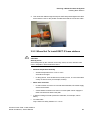
3.5.2 Where Not To Install DECT IP base stations . . . . . . . . . . . . . . . . . . . . . . . . . . . . . . . . . . . . . . . . . . . .
3.5.3 Where Should DECT IP base stations be installed? . . . . . . . . . . . . . . . . . . . . . . . . . . . . . . . . . . . . . .
3.5.4 Indoors . . . . . . . . . . . . . . . . . . . . . . . . . . . . . . . . . . . . . . . . . . . . . . . . . . . . . . . . . . . . . . . . . . . . . . . . .
3.5.4.1 Wall Mounting . . . . . . . . . . . . . . . . . . . . . . . . . . . . . . . . . . . . . . . . . . . . . . . . . . . . . . . . . . . . . . . .
3.5.4.2 Ethernet Socket Allocation in the DECT IP Base Station . . . . . . . . . . . . . . . . . . . . . . . . . . . . . . .
3.5.5 Tools/Aids . . . . . . . . . . . . . . . . . . . . . . . . . . . . . . . . . . . . . . . . . . . . . . . . . . . . . . . . . . . . . . . . . . . . . . .
32
32
34
35
36
36
37
38
40
40
40
42
46
46
50
50
51
52
53
53
54
55
A31003-C1010-S100-7-7620, 05/2014
HiPath Cordless IP, Service Documentation
3
bkTOC.fm
Contents
Nur für den internen Gebrauch
3.5.6 Outdoors . . . . . . . . . . . . . . . . . . . . . . . . . . . . . . . . . . . . . . . . . . . . . . . . . . . . . . . . . . . . . . . . . . . . . . .
3.5.6.1 Preparatory Tasks . . . . . . . . . . . . . . . . . . . . . . . . . . . . . . . . . . . . . . . . . . . . . . . . . . . . . . . . . . . .
3.5.6.2 Mast Installation . . . . . . . . . . . . . . . . . . . . . . . . . . . . . . . . . . . . . . . . . . . . . . . . . . . . . . . . . . . . . .
3.5.6.3 Wall Installation with Mounting Plate . . . . . . . . . . . . . . . . . . . . . . . . . . . . . . . . . . . . . . . . . . . . . .
3.5.6.4 Wall Mounting Without Mounting Plate . . . . . . . . . . . . . . . . . . . . . . . . . . . . . . . . . . . . . . . . . . . .
55
56
57
59
61
4 Putting Into Service . . . . . . . . . . . . . . . . . . . . . . . . . . . . . . . . . . . . . . . . . . . . . . . . . . . . . . . . . . . . . . . . . . . . 62
4.1 Preparation . . . . . . . . . . . . . . . . . . . . . . . . . . . . . . . . . . . . . . . . . . . . . . . . . . . . . . . . . . . . . . . . . . . . . . . . . 62
4.2 Entering the DECT System Number (DECT ARI). . . . . . . . . . . . . . . . . . . . . . . . . . . . . . . . . . . . . . . . . . . . 63
4.3 Overview IP adresses. . . . . . . . . . . . . . . . . . . . . . . . . . . . . . . . . . . . . . . . . . . . . . . . . . . . . . . . . . . . . . . . . 64
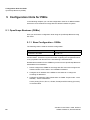
5 Configuration Hints for PBXs . . . . . . . . . . . . . . . . . . . . . . . . . . . . . . . . . . . . . . . . . . . . . . . . . . . . . . . . . . . 66
5.1 OpenScape Business (OSBiz) . . . . . . . . . . . . . . . . . . . . . . . . . . . . . . . . . . . . . . . . . . . . . . . . . . . . . . . . . . 66
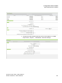
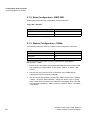
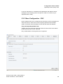
5.1.1 Base Configuration - OSBiz. . . . . . . . . . . . . . . . . . . . . . . . . . . . . . . . . . . . . . . . . . . . . . . . . . . . . . . . . 66
5.1.2 Base Configuration - BSIP-IWU . . . . . . . . . . . . . . . . . . . . . . . . . . . . . . . . . . . . . . . . . . . . . . . . . . . . . 68
5.1.3 Station Configuration - OSBiz . . . . . . . . . . . . . . . . . . . . . . . . . . . . . . . . . . . . . . . . . . . . . . . . . . . . . . . 68
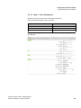
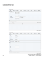
5.1.3.1 Step 1 - User Parameters . . . . . . . . . . . . . . . . . . . . . . . . . . . . . . . . . . . . . . . . . . . . . . . . . . . . . . 69
5.1.3.2 Step 2 - Workpointclient Data . . . . . . . . . . . . . . . . . . . . . . . . . . . . . . . . . . . . . . . . . . . . . . . . . . . 70
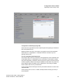
5.1.4 Station Configuration - HPCIP IWU. . . . . . . . . . . . . . . . . . . . . . . . . . . . . . . . . . . . . . . . . . . . . . . . . . . 70
5.2 HiPath 4000 . . . . . . . . . . . . . . . . . . . . . . . . . . . . . . . . . . . . . . . . . . . . . . . . . . . . . . . . . . . . . . . . . . . . . . . . 71
5.2.1 Base Configuration - HiPath 4000 . . . . . . . . . . . . . . . . . . . . . . . . . . . . . . . . . . . . . . . . . . . . . . . . . . . . 71
5.2.2 Station Configuration - HPCIP IWU. . . . . . . . . . . . . . . . . . . . . . . . . . . . . . . . . . . . . . . . . . . . . . . . . . . 73
5.3 OpenScape Voice (OSV) V7R1 . . . . . . . . . . . . . . . . . . . . . . . . . . . . . . . . . . . . . . . . . . . . . . . . . . . . . . . . . 74
5.3.1 General - OSV . . . . . . . . . . . . . . . . . . . . . . . . . . . . . . . . . . . . . . . . . . . . . . . . . . . . . . . . . . . . . . . . . . . 74
5.3.2 Base Configuration - OSV . . . . . . . . . . . . . . . . . . . . . . . . . . . . . . . . . . . . . . . . . . . . . . . . . . . . . . . . . . 75
5.3.3 Station Configuration - HPCIP IWU. . . . . . . . . . . . . . . . . . . . . . . . . . . . . . . . . . . . . . . . . . . . . . . . . . . 78
5.3.4 Limitations . . . . . . . . . . . . . . . . . . . . . . . . . . . . . . . . . . . . . . . . . . . . . . . . . . . . . . . . . . . . . . . . . . . . . . 78
6 Technical Data . . . . . . . . . . . . . . . . . . . . . . . . . . . . . . . . . . . . . . . . . . . . . . . . . . . . . . . . . . . . . . . . . . . . . . . . 79
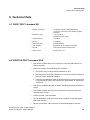
6.1 BSIP1 DECT standard EU . . . . . . . . . . . . . . . . . . . . . . . . . . . . . . . . . . . . . . . . . . . . . . . . . . . . . . . . . . . . . 79
6.2 BSIP1US DECT standard USA . . . . . . . . . . . . . . . . . . . . . . . . . . . . . . . . . . . . . . . . . . . . . . . . . . . . . . . . . 79
6.3 Base Stations . . . . . . . . . . . . . . . . . . . . . . . . . . . . . . . . . . . . . . . . . . . . . . . . . . . . . . . . . . . . . . . . . . . . . . . 81
6.3.1 HiPath Cordless IP server . . . . . . . . . . . . . . . . . . . . . . . . . . . . . . . . . . . . . . . . . . . . . . . . . . . . . . . . . . 84
6.3.2 PoE Injector . . . . . . . . . . . . . . . . . . . . . . . . . . . . . . . . . . . . . . . . . . . . . . . . . . . . . . . . . . . . . . . . . . . . . 84
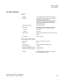
6.4 Item Number Overview . . . . . . . . . . . . . . . . . . . . . . . . . . . . . . . . . . . . . . . . . . . . . . . . . . . . . . . . . . . . . . . . 85
6.5 Measuring Equipment. . . . . . . . . . . . . . . . . . . . . . . . . . . . . . . . . . . . . . . . . . . . . . . . . . . . . . . . . . . . . . . . . 86
7 Diagnosis and Maintenance . . . . . . . . . . . . . . . . . . . . . . . . . . . . . . . . . . . . . . . . . . . . . . . . . . . . . . . . . . . . . 87
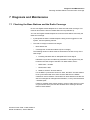
7.1 Checking the Base Stations and the Radio Coverage . . . . . . . . . . . . . . . . . . . . . . . . . . . . . . . . . . . . . . . . 87
7.1.1 Base Stations . . . . . . . . . . . . . . . . . . . . . . . . . . . . . . . . . . . . . . . . . . . . . . . . . . . . . . . . . . . . . . . . . . . 88
7.1.2 Quick Verification of Area Coverage . . . . . . . . . . . . . . . . . . . . . . . . . . . . . . . . . . . . . . . . . . . . . . . . . . 89
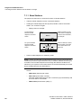
7.2 Testing the Radio Area . . . . . . . . . . . . . . . . . . . . . . . . . . . . . . . . . . . . . . . . . . . . . . . . . . . . . . . . . . . . . . . . 90
7.2.1 Significance of Results Obtained. . . . . . . . . . . . . . . . . . . . . . . . . . . . . . . . . . . . . . . . . . . . . . . . . . . . . 90
7.2.2 Gigaset Family. . . . . . . . . . . . . . . . . . . . . . . . . . . . . . . . . . . . . . . . . . . . . . . . . . . . . . . . . . . . . . . . . . . 92
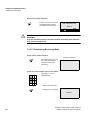
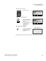
7.2.2.1 Activating Measuring Mode . . . . . . . . . . . . . . . . . . . . . . . . . . . . . . . . . . . . . . . . . . . . . . . . . . . . . 92
7.2.2.2 Deactivating Measuring Mode . . . . . . . . . . . . . . . . . . . . . . . . . . . . . . . . . . . . . . . . . . . . . . . . . . . 94
7.2.3 Documentation of Results . . . . . . . . . . . . . . . . . . . . . . . . . . . . . . . . . . . . . . . . . . . . . . . . . . . . . . . . . . 96
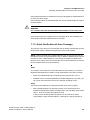
7.3 Troubleshooting . . . . . . . . . . . . . . . . . . . . . . . . . . . . . . . . . . . . . . . . . . . . . . . . . . . . . . . . . . . . . . . . . . . . . 99
7.3.1 Checking HiPath Cordless IP Components . . . . . . . . . . . . . . . . . . . . . . . . . . . . . . . . . . . . . . . . . . . . 99
7.3.2 What Happens If ... . . . . . . . . . . . . . . . . . . . . . . . . . . . . . . . . . . . . . . . . . . . . . . . . . . . . . . . . . . . . . . 100
7.3.2.1 Synchronism Symbol on Handset Display: . . . . . . . . . . . . . . . . . . . . . . . . . . . . . . . . . . . . . . . . 100
7.3.2.2 Handset Cannot Be Reached . . . . . . . . . . . . . . . . . . . . . . . . . . . . . . . . . . . . . . . . . . . . . . . . . . 101
7.3.2.3 Connection Handover . . . . . . . . . . . . . . . . . . . . . . . . . . . . . . . . . . . . . . . . . . . . . . . . . . . . . . . . 101
7.3.2.4 Handset: Problems Logging On . . . . . . . . . . . . . . . . . . . . . . . . . . . . . . . . . . . . . . . . . . . . . . . . . 102
4
A31003-C1010-S100-7-7620, 05/2014
HiPath Cordless IP, Service Documentation
bkTOC.fm
Nur für den internen Gebrauch
Contents
Index . . . . . . . . . . . . . . . . . . . . . . . . . . . . . . . . . . . . . . . . . . . . . . . . . . . . . . . . . . . . . . . . . . . . . . . . . . . . . . . . 103
A31003-C1010-S100-7-7620, 05/2014
HiPath Cordless IP, Service Documentation
5
c01.fm
Introduction and Important Notes
Safety Information and Warnings
1 Introduction and Important Notes
1.1 Safety Information and Warnings
Work on communication systems and devices may only be carried out by
qualified persons.
For the purposes of safety information and warnings, qualified persons are
persons who are authorized to place into operation, ground, and label systems,
devices, and lines in accordance with applicable safety procedures and
standards.
It is absolutely essential that you read and understand the following safety information and warnings before starting installation and implementation work on the
communication system or device.
You should also carefully read and observe all safety information and warnings
on the communication systems and devices themselves.
Familiarize yourself with emergency numbers.
6
A31003-C1010-S100-7-7620, 05/2014
HiPath Cordless IP, Service Manual
c01.fm
Introduction and Important Notes
Safety Information and Warnings
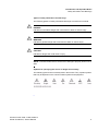
Types of safety information and warnings
The following grades of safety information/warnings are used in this manual:
7
DANGER
Indicates an immediate danger that could result in death or serious injury.
7
WARNING
Indicates a general danger that could result in death or serious injury.
7
CAUTION
Indicates a danger that could result in injury.
NOTE: Indicates situations that could result in damage to property and/or loss of
data.
Symbols for specifying the source of danger more exactly
The following symbols are not usually used in the manual. They explain symbols
that may be depicted on the communication systems and equipment.
•
A31003-C1010-S100-7-7620, 05/2014
HiPath Cordless IP, Service Manual
7
c01.fm
Introduction and Important Notes
Correct Use
1.2 Correct Use
The communications system may only be used for the purpose described in this
document and only in connection with the additional devices and components as
recommended and permitted by Unify GmbH & Co. KG.
The proper use of the communications system assumes correct
transport,storage, assembly and setup as well as careful operation and maintenance.
8
A31003-C1010-S100-7-7620, 05/2014
HiPath Cordless IP, Service Manual
c01.fm
Introduction and Important Notes
Proper disposal and recycling
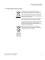
1.3 Proper disposal and recycling
All electrical and electronic products should be disposed of
separately from the municipal waste stream via designated collection
facilities appointed by the government or the local authorities.
The correct disposal and separate collection of your old appliance will
help prevent potential negative consequences for the environment
and human health. It is a precondition for reuse and recycling of used
electrical and electronic equipment.
For more detailed information about disposal of your old appliance,
please contact your city office, waste disposal service, the shop
where you purchased the product or your sales representative.
The statements quoted above are only fully valid for equipment which
is installed and sold in the countries of the European Union and is
covered by the directive 2002/96/EC. Countries outside the
European Union may have other regulations regarding the disposal
of electrical and electronic equipment.
Used accumulators and batteries with this sign are valuable
economic goods and must be recycled. Used accumulators and
batteries that are not recycled must be disposed of as hazardous
waste with full observance of all regulations.
A31003-C1010-S100-7-7620, 05/2014
HiPath Cordless IP, Service Manual
9
c01.fm
Introduction and Important Notes
Standards and Guidelines on Installation
1.4 Standards and Guidelines on Installation
1.4.1 Labeling
This device complies with the EU guideline 1999/5/EEC as
confirmed by the CE certificate.
This device has been manufactured in accordance with our
certified environmental management system (ISO 14001). This
process ensures that energy consumption and the use of
primary raw materials are kept to a minimum, thus reducing
waste production.
10
A31003-C1010-S100-7-7620, 05/2014
HiPath Cordless IP, Service Manual
c01.fm
Introduction and Important Notes
Data Protection and Data Security
1.5 Data Protection and Data Security
This system processes and uses personal data for purposes such as call detail
recording, displays, and customer data acquisition.
In Germany, the processing and use of such data is subject to various regulations,
including those of the Federal Data Protection Law (Bundesdatenschutzgesetz,
BDSG). For other countries, please follow the appropriate national laws.
The aim of data protection is to protect the rights of individuals from being
adversely affected by use of their personal data.
In addition, the aim of data protection is to prevent the misuse of data when it is
processed and to ensure that one’s own interests and the interests of other
parties which need to be protected are not affected.
The customer is responsible for ensuring that the system is installed,
operated and maintained in accordance with all applicable labor laws and
regulations and all laws and regulations relating to data protection, privacy
and safe labor environment.
Employees of Unify GmbH & Co. KG are bound to safeguard trade secrets and
personal data under the terms of the company’s work rules.
In order to ensure that the statutory requirements are consistently met during
service – whether on-site or remote – you should always observe the following
rules. You will not only protect the interests of your and our customers, you will
also avoid personal consequences.
A conscientious and responsible approach helps protect data and ensure
privacy:
•
Ensure that only authorized persons have access to customer data.
•
Take full advantage of password assignment options; Never give passwords
to an unauthorized person orally or in writing.
•
Ensure that no unauthorized person is able to process (store, modify,
transmit, disable, delete) or use customer data in any way.
•
Prevent unauthorized persons from gaining access to storage media, such as
backup CDs or log printouts. This applies to service calls as well as to storage
and transport.
•
Ensure that storage media which are no longer required are completely
destroyed. Ensure that no sensitive documents are left unprotected.
Work closely with your customer contact; this promotes trust and reduces
your workload.
A31003-C1010-S100-7-7620, 05/2014
HiPath Cordless IP, Service Manual
11
c01.fm
Introduction and Important Notes
Documentation Feedback
1.6 Documentation Feedback
If you have questions that are not answered by this document:
•
Internal employees should contact their National Support Center.
•
Customers should contact their retailer or the Unify Customer Support
Center.
When you call, please state the title and ID number of the document.
Example:
12
•
Title: HiPath Cordless IP, Service Documentation
•
ID number: A31003-C1010-S100-6-7620
A31003-C1010-S100-7-7620, 05/2014
HiPath Cordless IP, Service Manual
c02.fm
Overview
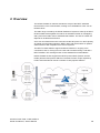
2 Overview
The HiPath Cordless IP solution extends the scope of the DECT standard
introduced for voice communication, making it now available for Voice over IP
infrastructures.
The radio range covered by the HiPath Cordless IP system is made up of DECT
IP base stations that together form either an seamless network of overlapping
and synchronous radio cells or individual radio islands. The size of a radio cell
depends on local/structural factors.
Voice over IP infrastructures are connected via the SIP protocol. In their capacity
as mobile communication solutions, DECT radio cells are therefore an optimal
enhancement to SIP-compliant Voice over IP systems.
The DECT IP base stations support seamless handover in ongoing voice
connections, that is, moving from one radio cell to another during a call with a
DECT handset. The roaming function is also available for mobile stations.
HiPath Cordless IP also supports the DECT protocol GAP (Generic Access
Profile) and the radio protocol PN-CAP. The basic function scope required by
ETSI is thus extended to include a number of Unify-specific features.
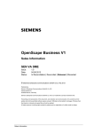
Figure 1
A31003-C1010-S100-7-7620, 05/2014
HiPath Cordless IP, Service Manual
General Overview of the HiPath Cordless IP System
13
c02.fm
Overview
The HiPath Cordless IP System contains the following main components, see
also Figure 1:
14
•
Handset: Gigaset professional DECT handsets with PN-CAP
functionality
•
BSIP1: DECT IP Basestations with GAP/ PN-CAP functionality to the
handset and IP interface to the Ethernet network.
•
HiPath Cordless IP SW: central Server SW component for control of the
DECT IP Basestations, SIP interworking with the communication server,
and the common administration and configuration interface of the whole
HiPath Cordless IP solution. The HiPath Cordless IP Server SW can
either be located on one of the DECT IP Basestations or on a dedicated
Server HW.
A31003-C1010-S100-7-7620, 05/2014
HiPath Cordless IP, Service Manual
c02.fm
Overview
Introduction
2.1 Introduction
The HiPath Cordless IP solution is designed as a DECT system with an SIP
interface to the communication server.
2.1.1 DECT IP Base Station (BSIP1)
DECT IP base stations combine to form a network of radio cells. Roaming
between radio cells is possible for DECT handsets during a voice connection if
the radio cells are synchronized and overlap.
DECT IP base stations come with all necessary software for the DECT and IP
functions. This software is configured and administered via the HiPath Cordless
IP SW.
2.1.2 HiPath Cordless IP SW
HiPath Cordless IP SW is installed once on a system and can be activated on a
DECT IP base station or can be installed on a server HW. It supports the following
functions:
Function: Router and protocol converter
The HiPath Cordless IP SW serves as the interface between the IP DECT base
stations and the communication server.
It manages the voice connections between the communication server and the
relevant DECT IP base station and converts these into a data format that can be
reed by the DECT IP base stations. At DECT layer the media packets are
enhanced with DECT signaling (time frame, frequency) information. The HiPath
Cordless IP SW converts incoming RTP media data into UDP packets via DECT
codec G726.
Only HiPath Cordless IP SW knows, at which DECT IP Basestation a special
DECT handset is located. For the communication server or any other phone, the
HiPath Cordless IP SW is the endpoint. Whenever a handset performs a
handover, this process is invisible outside the HiPath Cordless IP System. In the
view of the communication server the HiPath Cordless IP SW is like a Gateway
User-Agent that manages lots of handsets. Handsets use the HiPath Cordless IP
SW for registration at the communication server. This software regulates the
check-in procedure for the DECT handsets and their management.
Function: Configuration and administration interface
All administrative functionality for the DECT IP Basestations as well as for HiPath
Cordless IP SW itself is performed via a Web Based Management to the HiPath
Cordless IP SW, i.e., all DECT IP Basestations are administered via HiPath
Cordless IP SW.
A31003-C1010-S100-7-7620, 05/2014
HiPath Cordless IP, Service Manual
15
c02.fm
Overview
Introduction
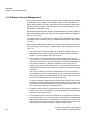
Function: Synchronization management
DECT IP base stations must be perfectly synchronized as a prerequisite for
seamless handover. If the DECT IP base stations are synchronized, they
combine to form a seamless handover cluster. The synchronization management
function only works in this cluster. Additional clusters are possible but not
synchronized. Seamless handover is not possible between different
asynchronous clusters.
In DECT systems with line-switched connections such as HiPath Cordless
systems, the synchronization information needed for synchronizing the DECT IP
base stations is obtained from the UP0 connection. This is not possible in the
HiPath Cordless IP system.
DECT-based synchronization ("synchronization over the air")
This method to synchronize overlapping radio cells runs under SW control within
the DECT part of the DECT IP Basestation. The HiPath Cordless IP SW is acting
only as admin point that notices when a base station has lost its synchronization.
The DECT IP base station must be located in the overlap area of the DECT IP
base station that it wants to synchronize with over the DECT interface. For every
DECT IP Basestation the synchronization "Master" have to be configured by the
configuration Interface of the HiPath Cordless IP SW. DECT information for
synchronization are exchanged directly between the DECT IP Basestations.
A DECT IP base station can also be synchronized with other DECT IP base
stations as this increases the synchronism available in the cluster. It is important
to avoid synchronization loops.
In the event of loss of synchronization, the DECT IP base station stops accepting
calls once all ongoing calls that were being conducted on the asynchronous
DECT IP base station have ended and then it re-synchronizes the asynchronous
DECT IP base station.
LAN-based synchronization
A DECT IP base station can be synchronized over LAN with another DECT IP
base station. The IEEE standard Precision Time Protocol (PTP) IEEE1588 is
used for this. In contrast to DECT-based synchronization, LAN-based
synchronization uses only one DECT IP base station in the cluster as the clock
master for the other DECT IP base stations to be synchronized. This PTP master
sends out multicast messages with time information. The slaves send back
modified time messages to the master.
In contrast to over-the-air synchronization, LAN-based synchronization requires
less configuration.
On the other hand, high demands are placed on Ethernet characteristics such as
symmetry, packet loss, delay, jitter (primarily delay variation). All of the Ethernet
components involved (especially the switches) therefore have to fulfill special
16
A31003-C1010-S100-7-7620, 05/2014
HiPath Cordless IP, Service Manual
c02.fm
Overview
Introduction
requirements. If thresholds are exceeded (primarily jitter), this leads to loss of
synchronization, which in turn leads to a resynchronization process. No calls can
be conducted on the relevant DECT IP base station during this process.
PTP messages are exchanged only between the DECT IP Basestations, the
HiPath Cordless IP SW is not involved.
DECT IP Basestations who are e.g. separated by iron doors cannot synchronize
each other over the air can use instead PTP.
For PTP, the underlying network must fulfill some restrictions like very little delay,
i.e., no routers or NAT devices (see chapter Section 2.4).
A combination of air and LAN synchronization is possible in a cluster of
synchronous DECT IP base stations.
Advantages of LAN synchronization compared with over-the-air synchronization:
•
Greater flexibility in the arrangement of the base stations as no
synchronization chains need to be formed.
•
Fewer DECT IP base stations required as the overlapping area of the DECT
IP base stations is smaller.
•
Configuration of the system is simplified as all DECT IP base stations can be
synchronized on one synchronization master.
In the event of loss of synchronization, the DECT IP base station stops accepting
calls once all ongoing calls that were being conducted on the asynchronous
DECT IP base station have ended and then it re-synchronizes the asynchronous
DECT IP base station.
Figure 2
Optimum system synchronization over DECT at synchronization
over the air
Standard synchronization
Alternative synchronization if standard synchronization fails
A31003-C1010-S100-7-7620, 05/2014
HiPath Cordless IP, Service Manual
17
c02.fm
Overview
Introduction
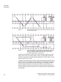
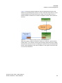
Figure 3
Not optimally synchronized, each DECT IP base station has only one
synchronization partner
Figure 4
The two lower DECT IP base stations are synchronized over LAN
because a solid fire door prevents DECT-based synchronization.
The quick passage of data through a fire door cannot always
guarantee reliable DECT synchronization.
This data is transported in a VPN tunnel to ensure that the signaling and voice
data in active voice connections between a DECT IP base station and HiPath
Cordless IP software is protected against manipulation and interception. For the
VPN encryption IPSec is used.
The DECT IP base stations are set up in communication with the HiPath Cordless
IP SW. As soon as a new DECT IP base station is connected to the Ethernet, it
starts to send multicast packets with its MAC address. The HiPath Cordless IP
SW then activates and takes over control of the DECT IP base station. The
HiPath Cordless IP SW then sends the DECT IP base station an IP address for
communication purposes as well as its own IP address as a future target address
for data traffic.
18
A31003-C1010-S100-7-7620, 05/2014
HiPath Cordless IP, Service Manual
c02.fm
Overview
Introduction
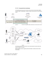
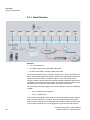
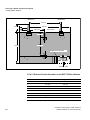
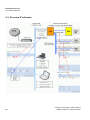
2.1.2.1 Communication Interfaces
The following picture gives an overview of the protocols used between DECT
Handset, DECT IP Basestation, HiPath Cordless IP SW and the communication
server.
Figure 5
Protocols of the path between Handset and Communication Server
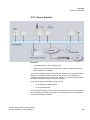
Figure 6
Depicts all communication channels of the HiPath Cordless IP
System
The following list gives an overview of all communication-channels within the
HiPath Cordless IP System:
DECT Handset - User: Gigaset professional DECT Handsets with PN-CAP
functionality
A31003-C1010-S100-7-7620, 05/2014
HiPath Cordless IP, Service Manual
19
c02.fm
Overview
Introduction
DECT Handset - DECT IP Basestation (BSIP1): In this multicell DECT system,
a call can be handed over seamlessly from one BSIP1 to the other. If seamless
handover is impossible and the signal quality is decreasing, at a certain point the
handset can send a warning tone and the connection breaks off.
DECT IP Basestation (BSIP1) - DECT IP Basestation (BSIP1): An accurate
synchronization is needed between DECT IP Basestation for seamless handover.
DECT IP Basestation (BSIP1) - HiPath Cordless IP SW: the DECT IP
Basestation (BSIP1) is able to handle a tunnel to the HiPath Cordless IP SW, in
which the voice data of all active calls and all signaling data is transported. The
connection between BSIP1 and HiPath Cordless IP SW is system-specific, i.e.,
this protocol is IP based and uses UDP packages both ways.
HiPath Cordless IP SW - communication server: The SIP interface between
the HiPath Cordless IP SW and the communication server is standard based.
Seen from the communication server the DECT over IP System is a set of SIP
subscribers represented by a GW User-Agent, which is the HiPath Cordless IP
SW connected to the DECT handsets, i.e. the subscribers are the DECT
handsets.
20
A31003-C1010-S100-7-7620, 05/2014
HiPath Cordless IP, Service Manual
c02.fm
Overview
System Configuration
2.2 System Configuration
There are three main scenarios for installing the HiPath Cordless IP solution:
•
The HiPath Cordless IP Small Solution
•
The HiPath Cordless IP Server Solution
•
The HiPath Cordless IP Large Solution
In all cases, all voice and signaling data (RTP/SIP) are always routed over the
HiPath Cordless IP SW because this is the only software that supports a routing
and protocol converter function.
Scenarios are also possible where the HiPath Cordless IP SW is installed a
number of times per communication server. Such scenarios do not support
seamless handover between the different clusters formed with synchronous
DECT IP base stations. Cascading is not available at present for communication
server software.
A31003-C1010-S100-7-7620, 05/2014
HiPath Cordless IP, Service Manual
21
c02.fm
Overview
System Configuration
2.2.1 Small Solution
Definition
•
1 to 10 base btations
•
One base station running with BSIP-IWU Mode
•
All other base stations running in BSIP-Only Mode
The HiPath Cordless IP Server SW (Inter Working Unit - IWU) is activated on a
DECT IP base station (BSIP-IWU Mode). All DECT IP base stations always also
support the same functions as HiPath Cordless IP SW. This means that in
principle, all DECT IP base stations can perform HiPath Cordless IP SW functions
in addition to the actual DECT functionality. The HiPath Cordless IP SW must be
activated before the DECT IP base station can perform this function.
The following system limits apply in this scenario based on resource availability
in BSIP1:
–
up to 10 DECT IP base stations
–
up to 10 parallel calls
These system limits apply to each cluster of synchronous DECT IP base stations
where seamless handover is possible. Up to 99 Gigaset professional mobile
devices can be configured in the data base of the HiPath Cordless IP SW and up
to 55 of these mobile devices can be logged on to the Communication Server.
22
A31003-C1010-S100-7-7620, 05/2014
HiPath Cordless IP, Service Manual
c02.fm
Overview
System Configuration
2.2.2 Server Solution
Definition
•
1 to 60 base stations and 1 HPCIP server
•
1 HPCIP server running with HPCIP server mode (= Management Server
Mode + Media Server Mode)
The HiPath Cordless IP Server SW (IWU) is installed on a server (HCIP Server
Mode). The requisite operating system for the server is Linux Distribution
openWRT. Both the server and the entire software on the server are included in
the HiPath Cordless IP solution’s scope of features.
The following system limits apply in this scenario:
–
up to 60 DECT IP base stations
–
up to 50 parallel calls
These system limits apply to each cluster of synchronous DECT IP base stations
where seamless handover is possible. Up to 300 Gigasets can be configured in
the HiPath Cordless IP software.
A31003-C1010-S100-7-7620, 05/2014
HiPath Cordless IP, Service Manual
23
c02.fm
Overview
System Configuration
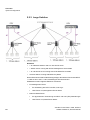
2.2.3 Large Solution
Definition
•
1 to 3000 base stations and 2 to 100 HPCIP server
•
1 HPCIP server running with HPCIP Management Server Mode
•
1 to 100 HPCIP server running with HCIP Media Server Mode
•
All base stations running with BSIP-Only Mode
Dieses Szenario durchbricht die bisherige Regel, dass auf der IWU sowohl DECT
<> IWU als auch VoIP <> IWU Verbindungen terminiert werden.
Stattdessen werden folgende Elemente verwendet
•
•
24
Ein Management Server
•
Zur Verbindung der DECT und SIP „Call Legs“
•
HCIP Server im „Management Server Mode“
Mehrere Media Server
•
Zur phyikalischen Terminierung der DECT und VoIP (SIP) Verbindungen
•
HCIP Server im „Media Server Mode“
A31003-C1010-S100-7-7620, 05/2014
HiPath Cordless IP, Service Manual
c02.fm
Overview
System Configuration
Durch diese Architektur wird eine Layer 3 Separierung möglich.
Der Management Server verbindet die DECT und VoIP (SIP) Elemente der
Anrufe „Call Legs“.
Die Layer 3 Separierung (Zweigstellen Konzept) wird durch die
Netzwerkverbindungen zwischen dem Management Server und den Media
Servern möglich.
Sie stellt eine zentrale Konfiguration, über alle Media Server hinweg, zur
Verfügung.
Der Media Server ist ein neuer Layer zwischen Management Server (IWU) und
BSIP1 Basistationen.
Der Media Server terminiert die IP Verbindungen hin zu den Basistationen und
dem SIP Registrar.
Alle BSIP1 Basistationen werden über Layer 2 an einen Media Server
angeschlossen.
Es gibt Media Server 30, 60, 90 und 120, wobei die Nummer für die Zahl
gleichzeitiger DECT Verbindungen steht.
Media Server der Large Solution können NICHT auf einem BSIP1 betrieben
werden.
Formal verfügen die BSIP-only und die Server Solution bei der Konfiguration
ebenso über einen (einzigen und nicht konfigurierbaren) Media Server: Das
MGW Local.
Ein Standort ist eine neue Größe für eine Zweigstelle, die durch Gruppierung von
bis zu 5 Media Servern entsteht.
Formal verfügen die BSIP-only und die Server Solution bei der Konfiguration
ebenso über einen (einzigen und nicht konfigurierbaren) Standort.
A31003-C1010-S100-7-7620, 05/2014
HiPath Cordless IP, Service Manual
25
c02.fm
Overview
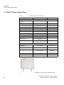
DECT IP Base Station Data
2.3 DECT IP Base Station Data
Table 1
Technical data DECT IP base station
Parameter
DECT IP base station BSIP1
Outdoor case
DECT Interface
Max. amount of DECT
channels
DECT Signalling
120
GAP/ PN-CAP
IP Interface
Network connection
Ethernet 10/100 Base T
PoE class
Class 2 according IEE802.3af
Power consumption
< 6,5 W; PoE Class 2
Max. Voice channels
12 (at G.711)
Codecs
G.711/ G.726
QoS
802.1 p/q
Echo Cancellation
yes
DHCP Option
DCHP on or local entry of IP
addresses
SW Distribution
SW Download/ Update central
via HiPath Cordless IP SW
Miscellaneous
Dimensions
(W x H x D in mm)
202 x 256 x 90
296 x 256 x 90
Weight
approx. 0,5 kg
approx. 1,0 kg
Operating Temperature
Indoors:
0 oC to + 40 oC
Outdoors (with outdoor
housing):
- 25 oC to + 40 oC
Storage temperatur range
-5 oC to + 45 oC
Relative humidity
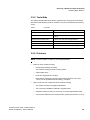
Figure 7
26
–
to 95 %
DECT IP base station BSIP1 (Item number: U30807-S5494-X)
A31003-C1010-S100-7-7620, 05/2014
HiPath Cordless IP, Service Manual
c02.fm
Overview
DECT IP Base Station Data
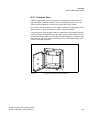
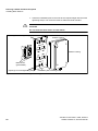
2.3.1 Outdoor Case
A DECT IP base station must be installed in a weatherproof outdoor case to
guarantee radio coverage in outdoor areas, for example on factory sites. The
outdoor case is suitable for mounting on house walls, roofs or masts.
The outdoor case already used for the HiPath Cordless base station BS4 is also
used for DECT IP base stations (part number: S30122-X7469-X2).
If using the DECT IP base station outdoors, lightning and overvoltage protection
must be provided and guaranteed for the DECT IP base station itself as well as
for the feeder into the DECT IP base station and the building. In compliance with
EN 61000-4-5, the power supply inlet on the DECT IP base station offers up to
0.5 KV overvoltage protection.
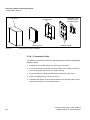
Outdoor Case
Figure 8
A31003-C1010-S100-7-7620, 05/2014
HiPath Cordless IP, Service Manual
Outdoor case with DECT IP base station
27
c02.fm
Overview
DECT IP Base Station Data
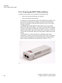
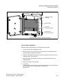
2.3.2 Powering the DECT IP Base Stations
The DECT IP base station can be powered in two different ways:
•
Power-over-Ethernet (PoE) Class 2 to 802.3af
•
Power-over-Ethernet: PoE injectors
A PoE injector is used if PoE cannot be made available in the network. The
PoE injector must be 802.3af-compatible. Pre-tested and released PoE
injectors are available as optional features within the scope of the HiPath
Cordless IP solution.
The IEEE802.3af standard allows the PoE Injector to be in any location
between the switch and the BSIP1. The maximum allowed distance between
the switch and the BSIP1 for IEEE802.3 compliance is 100 m. It is typical to
deploy the PoE Injector close to the switch, since by doing this one can use
a single UPS (central power supply) to backup both the switch and the PoE
Injector.
If overall efficiency is more important than centralized backup and/or
management, it makes sense to place the PoE Injector closer to the BSIP1,
since the power dissipated at the cable between the PoE Injector and the
BSIP1 is directly proportional to the length of this cable (P = I2 * R).
Figure 9
28
PoE Injector
A31003-C1010-S100-7-7620, 05/2014
HiPath Cordless IP, Service Manual
c02.fm
Overview
Network Requirement
2.4 Network Requirement
Voice connections only work properly over IP networks if the IP network satisfies
all general VoIP network requirements in terms of delay, loss and guaranteed
quality of service features.
The following conditions should also be assured for the DECT IP base stations
and the HiPath Cordless IP SW in the IP network:
•
they have to be part of the same Ethernet segment, a layer-3 routing via
an IP router is not supported,
•
no devices use the Network Address Translation (NAT) Ethernet segment
•
Minimum 2 priority classes acc. to IEEE 802.1 p/q in the IP Network
possible
•
Use of 100 Mbps full duplex for all switched LAN ports
•
as the solution operates with standard IP addresses, these must be freely
available in the IP network.
Failure to satisfy these conditions can result in delays in the IP network. This
leads to synchronization and voice quality problems in the DECT handsets.
A31003-C1010-S100-7-7620, 05/2014
HiPath Cordless IP, Service Manual
29
c02.fm
Overview
Software License Management
2.5 Software License Management
SW component licensing is only relevant if the HiPath Cordless IP SW is installed
on dedicated server hardware. If the HiPath Cordless IP SW is activated on a
DECT IP base station, licensing is not performed for the software components of
HiPath Cordless IP systems. The SW licensing of the communication server’s
SIP stations is dependent on this.
If the HiPath Cordless IP SW is located on a dedicated Server HW the number of
DECT IP Basestation within the system and the HiPath Cordless IP SW itself in
Version 1 is licensed.
The number of DECT IP base stations configured and registered in the HiPath
Cordless IP SW is counted for this. The HiPath Cordless IP SW is also counted
in version 1.
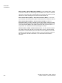
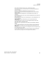
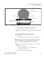
HiPath License Management (HLM) is used in the HiPath Cordless IP SW. The
Unify licensing process consists of 4 different steps, see for a general overview
Figure 10:
1. The license key is centrally created and contains the number of DECT IP
Basestations in the system and the number of HiPath Cordless IP SW in
Version 1. The license file is signed by Unify CA.
2. The license file is being download from a License Server (CLS, Central
License Server). In general, the Customer Site Components (CSC) are part
of the license SW of the product that interpret the license file and distribute it
in a customer's network. In detail, the Customer License Agent (CLA) usually on the Unify communication server - connects to the License Server
and downloads the license file. Via CLA the customer can monitor the usage
of licenses.
If the CLA is located on the Unify communication server, the license file is
downloaded onto the Unify communication server. A Customer License Client
(CLC) which is always on HiPath Cordless IP SW, is told, under which link on
the Unify communication server it can contact the CLA.
In case the customer's network does not have a Unify communication server
the HiPath Cordless IP SW itself will also be provided with CLA SW and the
license file will be downloaded directly onto the HiPath Cordless IP SW. The
CLC is told that the files are on the same server.
3. Verification of the license key: the license file is read in and the signature is
checked. If the check is successful, the license data will be retrieved from the
license file. This is done by CLA.
4. License Enforcement: the license conditions are checked and supervised in
the running system, e.g., as soon as a DECT IP Basestation is installed and
added to the system, the CLC contacts the CLA and a license counter in the
license file is decremented. This step is performed by the Customer License
Client (CLC) that is always running on HiPath Cordless IP SW.
30
A31003-C1010-S100-7-7620, 05/2014
HiPath Cordless IP, Service Manual
c02.fm
Overview
Software License Management
Figure 10 shows the HiPath Cordless IP license management as part of the
HiPath License Management (HLM). CLS is the Central License Server. CLA is
usually installed on the same Server as the Unify communication server. In
HiPath Cordless IP SW the CLC module is integrated, which is the interface to
the CLA.
Figure 10
HiPath Cordless IP SW: License Management
When the HiPath Cordless IP System is setup at a customer, a special Grace
Period starts, i.e. the product can be used for 30 days without a license. Within
this period of time, the one who is installing the system has to get a valid product
license. After installation of the license software on the system, this license has
no more time restrictions.
A31003-C1010-S100-7-7620, 05/2014
HiPath Cordless IP, Service Manual
31
c03.fm
Planning a HiPath Cordless IP System
Planning According to Call Traffic Load
3 Planning a HiPath Cordless IP System
When planning a cordless system, the position of the base station is critical for
system performance. The load should be optimized using locations with a high
call volumes and radio coverage.
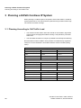
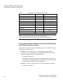
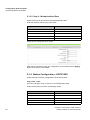
3.1 Planning According to Call Traffic Load
•
The borders of base station radio cells should not be located in high traffic
areas because changing base stations during a call (handover) increases
traffic load.
•
The best base should be as unique as possible to avoid frequent switching.
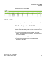
Recommended number of DECT users (number of simultaneously registered
users) for 10 voice channels in accordance with the volume of traffic (Erlang
value).
10 Voice channels with 100 mErl/user (low traffic)
Grad of Service (GoS)
0,1 %
1%
Traffic
3,09 Erl
4,46 Erl
User
31
45
10 Voice channels with 150 mErl/user (normal traffic)
Grad of Service (GoS)
0,1 %
1%
Traffic
3,09 Erl
4,46 Erl
User
21
30
10 Voice channels with 200 mErl/user (high traffic)
Grad of Service (GoS)
0,1 %
1%
Traffic
3,09 Erl
4,46 Erl
User
15
22
Table 2
32
Recommended amount of users at 10 voice channels
A31003-C1010-S100-7-7620, 05/2014
HiPath Cordless IP, Service Manual
c03.fm
Planning a HiPath Cordless IP System
Planning According to Call Traffic Load
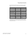
Recommended number of DECT users (number of simultaneously registered
users) for 50 voice channels in accordance with the volume of traffic (Erlang
value).
50 Voice channels with 100 mErl/user (low traffic)
Grad of Service (GoS)
0,1 %
1%
Traffic
32,51 Erl
37,90 Erl
User
325 *
379 *
50 Voice channels with 150 mErl/user (normal traffic)
Grad of Service (GoS)
0,1 %
1%
Traffic
32,51 Erl
37,90 Erl
User
217
253
50 Voice channels with 200 mErl/user (high traffic)
Grad of Service (GoS)
0,1 %
1%
Traffic
32,51 Erl
37,90 Erl
User
163
190
Table 3
Recommended amount of users at 10 voice channels
(*) At the time an amount of 300 Gigaset professional (subscriber) is possible,
althoug theoretically a higher amount of Gigaset professional would be possible
according to traffic intensity.
A31003-C1010-S100-7-7620, 05/2014
HiPath Cordless IP, Service Manual
33
c03.fm
Planning a HiPath Cordless IP System
General
3.2 General
DECT IP Base station (BSIP1)
DECT IP base stations are logically connected to the HiPath Cordless IP server
software over LAN connections. This software is connected to the communication
server via the SIP interface.
•
Base station range
–
Ethernet cable range (see also Chapter 2.4 for network requirements
between DECT IP base stations and the HiPath Cordless IP server
software)
–
Spatial distance
The distance which must be maintained between the different installation
points of the base stations is dependent on
–
–
the range
–
the traffic capacity of the radio cells.
You can increase the number of simultaneous calls in a radio cell by
overlapping radio cells (overload).
–
Distance
For synchronization over DECT, the DECT IP base stations you want
to synchronize with each other must be able to exchange their
management information (beacons). For this to work, they must be
located in the areas where their radio cells overlap.
This does not apply for use of over-the-air synchronization.
Overlap areas inside/outside buildings (see following chapter),
measurement results (RSSI points).
Radio measurement techniques are used to determine the radio range of DECT
IP base stations.
DECT IP base stations inside buildings
–
Please note that the base station’s connection cable can be repositioned
as necessary (connection cable plus reserve loop to be factored in).
DECT IP base stations in areas outside buildings (e.g. campuses).
•
–
The base station must be installed in the outdoor case for use is exterior
areas.
–
Make sure that adequate lightning and overvoltage protection is provided
for the cable feeder into the building and the DECT IP base station
Radio propagation
Radio propagation is negatively influenced by
34
A31003-C1010-S100-7-7620, 05/2014
HiPath Cordless IP, Service Manual
c03.fm
Planning a HiPath Cordless IP System
Propagation Conditions for Radio Traffic
–
obstructions with strong absorption qualities (brick walls, dividing walls,
ceilings, furniture, steel cabinets, bathroom units, elevators, wirereinforced glass, leaded windows, blinds and others)
–
reflective stationary obstructions (brick buildings, reinforced concrete
buildings, buildings with metal sheathing)
–
reflective moving obstructions (people, animals, vehicles)
3.3 Propagation Conditions for Radio Traffic
Radio wave propagation in the DECT frequency range is quasioptical. This
means that a wave is hindered in its propagation if it hits a solid surface and is
thereby reflected to a greater or lesser extent. This reflection is dependent on the
physical qualities of the medium.
In the case of conductive materials, the penetration depth into the medium is
determined mainly by the magnetic quality and the electrical conductivity.
•
Metals with a high degree of conductivity
These include copper or steel and prevent most DECT frequency radio waves
from penetrating, reflecting them in the same way as a mirror reflects light.
•
Modern construction materials (exceptions, see above)
These have relatively poor conductivity levels with the result that
electromagnetic waves, even if attenuated, still can pass through.
Thus, radio traffic is possible within and through buildings.
•
Attenuation qualities
of the construction materials vary greatly resulting in different ranges
depending on the propagation direction and the construction material
penetrated.
– Wood (dry and unprocessed),
glass, plastics (N-conductor)
negligible attenuation
– Brick walls,
wood (damp and processed, for example,
particle board)
medium range of attenuation
– Reinforced concrete, glass with metal
reinforcement/coating
greatest attenuation
This attenuation is mitigated by openings, especially by windows in the
buildings as long as they do not have wire-reinforced or metal-plated glass.
The different levels of radio propagation give rise to various scenarios in which
radio cells are formed:
•
in the open with visibility
•
industrial sites with reinforced concrete buildings and buildings with metal
facades
A31003-C1010-S100-7-7620, 05/2014
HiPath Cordless IP, Service Manual
35
c03.fm
Planning a HiPath Cordless IP System
Propagation Conditions for Radio Traffic
•
indoor areas in buildings made of brick and light construction materials
•
indoor areas in reinforced concrete buildings with diverse interior layout,
for example.
3.3.1 In the Open with Visibility
In this scenario, the electromagnetic waves are subject to the lowest amount of
attenuation with the result that they produce the greatest radio wavelength.
In principle, base stations in such a scenario produce a radio coverage range with
a radius of up to 300 m.
This, however, is usually not possible, since trees, bushes and moving
obstructions, such as, people, animals, and vehicles in the direct propagation
route can significantly reduce propagation.
NOTE: A base station installed in an attic directly beside a dormer window
(no metal reinforcement in the window pane) is the alternative to the outdoor
housing for coverage of the outdoor area.
Choose the mounting location carefully:
The base station is often exposed to extreme environmental temperatures, for
example, direct sunlight or extreme cold.
3.3.2 Industrial Sites
Buildings of varying structural materials may be found here, including those:
•
of light construction materials,
•
of brick,
•
of reinforced concrete,
•
with metal facades.
The distances between the buildings, however, are rarely greater than 100 m. In
this scenario, outdoor base stations are practical for covering the outdoor area.
•
Buildings of brick or light construction materials
are generally penetrable, but the magnetic field reception behind the walls is
extremely low, resulting, quasioptically, in a shadowed area.
For example, in the case of a base station installed on the southern side of a
brick building, the range limit on the northern side would be attained
immediately or after just a few meters, owing to the insertion loss.
36
A31003-C1010-S100-7-7620, 05/2014
HiPath Cordless IP, Service Manual
c03.fm
Planning a HiPath Cordless IP System
Propagation Conditions for Radio Traffic
Up to 100 m of the outdoor area can also be supplied through the windows.
For this purpose, the base station must be set up on an upper floor (> 3rd
floor, that is two levels above ground floor). Low-lying obstructions near the
base station, such as, vehicles or a garage (one or two cars) do not, in this
case, cause significant interference.
•
Reinforced concrete buildings and/or metal facades:
These have proven to be limiting factors. Penetration into the building is only
possible through windows (up to about 2 m into the building in the case of
standard size windows). The windows cannot be made from wire-reinforced
or metal-plated glass.
Wave conduction is possible in alleys between buildings as well as along
streets. This results in a larger radio area.
3.3.3 Indoor Areas in Buildings in Brick and Light
Construction Materials
•
Insertion loss values
In the case of walls of brick or light construction materials, insertion loss
values are relatively small so that even dividing walls of up to 30 m can be
penetrated.
•
Vertical attenuation
This is dependent on the ceiling type. In this case, reinforced concrete
ceilings that offer higher attenuation in particular compared to brick play a
decisive role in range evaluation.
These ceilings are dimensioned based on the purpose of the building, for
example,
–
single-family residence
–
apartment building
–
office building
–
theater
and so the insertion loss ae also differs accordingly; see Table 4.
A31003-C1010-S100-7-7620, 05/2014
HiPath Cordless IP, Service Manual
37
c03.fm
Planning a HiPath Cordless IP System
Propagation Conditions for Radio Traffic
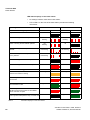
Table 4
Insertion loss (ae)/range loss in the radio area
Insertion object
ae (dB)
Range loss (%)
2.5
~ 43.5
4
~ 60
Brick wall, 63 to 70 cm
4.0 to 4.5
~ 60 to 64
Drywall
1.3 to 2.3
~ 26.5 to 41
6.6
~ 78
Glass wall
2
~ 37
Wire-reinforced glass wall
8
~ 84
6 to 9
~ 75 to 87
Two reinforced concrete ceilings
26
~ 99.5
Three reinforced concrete ceilings
46
100
Brick wall, 10 to 12 cm
Brick wall, 24 cm, small windows
Gaseous-concrete wall
Reinforced concrete ceiling
(residence)
NOTE: These values show clearly that propagation within buildings is hindered
much less in a horizontal direction than in a vertical direction.
This must be taken into consideration when installing the base station.
3.3.4 Indoor Areas in Reinforced Concrete Buildings
with Diverse Interior Layout
Indoor areas in reinforced concrete buildings can give rise to different scenarios,
depending on the interior layout.
•
Scenario 1 - Large factory halls (for manufacturing or office space)
These are either not partitioned (e.g. manufacturing halls) or have mobile
partitions reaching half way to the ceiling (office).
–
Propagation conditions
Favorable in this scenario because intervisibility is more frequent than,
for example, in buildings divided into individual offices with no line of sight
between the base station and mobile telephones.
•
Scenario 2 - Interior in buildings of brick and light construction materials
–
38
Propagation conditions
A31003-C1010-S100-7-7620, 05/2014
HiPath Cordless IP, Service Manual
c03.fm
Planning a HiPath Cordless IP System
Propagation Conditions for Radio Traffic
Similar to buildings with brick outer walls.
However, due to industrial sector requirements, the dimensions of
reinforced concrete ceilings in these buildings are such that insertion loss
values are considerably higher than in brick buildings.
NOTE: The resulting unfavorable vertical wave propagation must be taken into
consideration when installing the base station.
•
Scenario 3 - Interior with concrete walls and steel dividing walls
These areas also usually include the heavily steel-reinforced areas of
–
stairwells,
–
bathroom areas,
–
supply shafts, as well as
–
elevator shafts.
Table 5 shows several insertion loss values which are relevant to this
scenario, along with the corresponding capacity loss data for the radio area.
Table 5
Insertion loss (ae)/range loss in the radio area
Insertion object
ae (dB)
Range loss (%)
Concrete wall, interior, 10 cm
6
~ 75
Concrete wall, double, 2 x 20 cm
17
~ 97.5
Concrete wall, 25 to 30 cm
9.4 to 16
~ 88 to 97.5
Reinforced concrete ceiling
12 to 14
~ 91 to 96
Two reinforced concrete ceilings
35 to 47
100
Three reinforced concrete ceilings
42 to 53
100
Steel wall with wire-reinforced glass
6.5 to 10
~ 75.5 to 90
Steel walls, extending to ceiling, 3.5 m dist.
31 to 41
100
–
Propagation conditions
Horizontal and vertical values are approximately the same. It has been
determined that in this type of building, transmission usually takes place
along corridors if steel divider walls are installed.
As the relatively high insertion loss values show, individual rooms are
increasingly supplied via reflection if multiple metal walls are in the direct
path.
Concrete walls cause similar conditions to those described above.
Elevator shafts and stairwells must therefore often have their own base
station if they are to be included in the HiPath Cordless IP range.
A31003-C1010-S100-7-7620, 05/2014
HiPath Cordless IP, Service Manual
39
c03.fm
Planning a HiPath Cordless IP System
Determining the Installation Site
3.4 Determining the Installation Site
3.4.1 Indoors
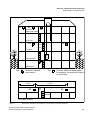
3.4.1.1 In Buildings of Brick or Light Construction Materials
•
Horizontal direction
A base station must be installed at least every 50 m.
•
Central installation in the building
The general rules must be observed.
•
Vertical coverage
Care must be taken to ensure that no more than two reinforced concrete
ceilings are in the direct propagation route between the base station and
the area of movement of the handsets.
Other base stations must then be set up in the radio cells if necessary,
based on the concentration of stations or the number of handsets.
Assuming that the distribution of handsets in buildings will be fairly uniform,
additional base stations should preferably be installed on the floors above or
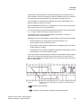
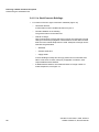
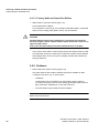
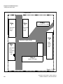
below the minimum required base stations (see Figure 11).
40
A31003-C1010-S100-7-7620, 05/2014
HiPath Cordless IP, Service Manual
c03.fm
Planning a HiPath Cordless IP System
Determining the Installation Site
BS Z
BS
Z
3rd floor
Open-plan office
BS
2nd floor
BS
1st floor
BS
Stairwell
Elevator
Ground floor
BS
Basement
BS
Minimum required
base station
Z
Possible additional base station,
for example, for areas with higher s
concentration
< 50 m
< 25 m
BS
BS
Stairwell
BS
Elevator
Floor plan 1st floor
Figure 11
Base station distribution in buildings of brick and light construction materials
A31003-C1010-S100-7-7620, 05/2014
HiPath Cordless IP, Service Manual
41
c03.fm
Planning a HiPath Cordless IP System
Determining the Installation Site
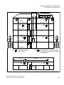
3.4.1.2 In Steel/Concrete Buildings
•
For interiors of brick or light construction materials (Figure 12)
–
Horizontal direction
A base station must be installed at least every 50 m.
–
Central installation in the building
The general rules must be observed.
–
Vertical coverage
Care must be taken to ensure that not more than one reinforced concrete
ceiling is in the direct propagation route between the base station and the
area where the mobile telephones are used. Adequate coverage cannot
otherwise be guaranteed.
–
Stairwells,
–
elevator shafts and
–
supply shafts
in these buildings usually have strongly-reinforced concrete walls and
stairs. Areas such as these, with poor propagation conditions, often
require additional base stations.
–
42
If additional base stations are needed because of a large number of
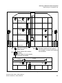
mobile telephones, see Figure 12.
A31003-C1010-S100-7-7620, 05/2014
HiPath Cordless IP, Service Manual
c03.fm
Planning a HiPath Cordless IP System
Determining the Installation Site
BS
Z
BS
BS
3rd floor
Open-plan office
Z
BS
Z
Open-plan office
BS
BS
2nd floor
Stair-
1st floor
well
BS
BS
Elevator
Ground floor
BS
Basement
BS
Minimum required
Base station
Z
Possible additional base station,
for example, for areas with higher s
concentration
< 50 m
< 25 m
BS
BS
Stairwell
BS
Elevator
Floor plan 2nd floor
Figure 12
Base station distribution in interiors of brick and light construction materials
A31003-C1010-S100-7-7620, 05/2014
HiPath Cordless IP, Service Manual
43
c03.fm
Planning a HiPath Cordless IP System
Determining the Installation Site
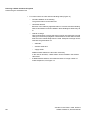
•
For interiors with concrete and steel dividing walls (Figure 13)
–
Central installation in the building
The general rules must be observed.
–
Horizontal direction
Because of the relatively high attenuation of concrete and steel dividing
walls, a base station must be installed in these buildings at least every 25
m.
–
Vertical coverage
Care must be taken to ensure that not more than one reinforced concrete
ceiling is in the direct propagation route between the base station and the
area where the mobile telephones are used. Adequate coverage cannot
otherwise be guaranteed. For
–
stairwells,
–
elevator shafts and
–
supply shafts
additional base stations are also often necessary.
In the case of elevators, a base station can be installed in the elevator
cabin itself.
–
44
If additional base stations are needed because of a large number of
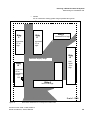
mobile telephones, see Figure 13.
A31003-C1010-S100-7-7620, 05/2014
HiPath Cordless IP, Service Manual
c03.fm
Planning a HiPath Cordless IP System
Determining the Installation Site
BS
3rd floor
Open-plan office
BS
BS
BS
Z
BS
BS
Open-plan office 2
Z
BS
Z
2nd floor
Stair-
1st floor
well
BS
Elevator
BS
BS
Z
Ground floor
Basement
BS
< 12 m
< 25 m
Z
BS
Minimum required
Base station
< 25 m
< 25 m
Z BS
BS
BS
Stairwell
Possible additional base station,
for example, for areas with higher s
concentration
BS
BS
Elevator
Floor plan 3rd floor
Figure 13
Base station distribution in interiors with concrete and steel dividing walls
A31003-C1010-S100-7-7620, 05/2014
HiPath Cordless IP, Service Manual
45
c03.fm
Planning a HiPath Cordless IP System
Determining the Installation Site
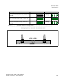
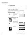
3.4.1.3 Factory Halls and Open-Plan Offices
•
Within halls or open-plan offices (Figure 12)
Good transmission qualities.
For a hall which is 100 m long, one centrally located base station, suspended
freely from the ceiling (mast, plastic chain), may be sufficient.
7
CAUTION
The base station should not be installed on a reinforced concrete pillar
because the pillar creates a partial shadow which means that a clear line of
sight no longer exists.
In this case, two base stations must be installed 50 m to 75 m apart.
In the case of outer walls or interior siding and/or hall ceilings made of metal
(or metal-clad), it may be necessary to increase the number of base stations
and distribute them in such a way as to virtually exclude radio interference
through reflections.
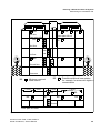
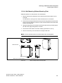
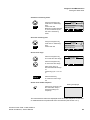
3.4.2 Outdoors
•
Base station with outdoor housing (Figure 14)
Only base stations with weather-resistant housing are suitable for radio
coverage out of doors, e.g. on factory sites.
–
Installation
A base station can be installed on a mast made of wood, plastic or
concrete (not metal), on the roof of a building (preferably made of brick or
light construction materials) or on the wall of a house.
–
The mast used must be stable and wind-resistant.
NOTE: Choose the installation site to allow maximum visibility from the base
station to the service area.
46
A31003-C1010-S100-7-7620, 05/2014
HiPath Cordless IP, Service Manual
c03.fm
Planning a HiPath Cordless IP System
Determining the Installation Site
Z
BS
BS
Z
BS
3rd floor
Open-plan office
2nd floor
BS
BS
1st floor
BS
Stair-
BS
well
BS
Elevator
Ground floor
BS
Basement
BS
BS
Minimum required
Base station
BS
Base station with outdoor
housing
Mast made of wood, plastic,
concrete (not metal)
Possible additional base station,
for example, for areas with higher s
concentration
< 50 m
< 25 m
BS
Z
Stairwell
BS
Elevator
Floor plan 1st floor
Figure 14
Base station distribution for base stations with housing for outdoor use
A31003-C1010-S100-7-7620, 05/2014
HiPath Cordless IP, Service Manual
47
c03.fm
Planning a HiPath Cordless IP System
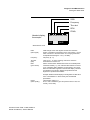
Determining the Installation Site
Example: Planning an outdoor area (Figure 15)
NOTE: A base station installed in an attic directly beside a dormer window (no
metal reinforcement in the window pane) is the alternative to outdoor housing for
coverage of the outdoor area.
•
Planning
A site plan, for example, with a scale of 1:300 or 1:1000 is helpful for
determining the base station installation site.
•
–
The customer’s preferred radio area should be indicated on the map
(subject to customer confirmation).
–
Additional information about the types and heights of buildings is also
helpful.
–
Radio coverage can be adequately determined with the aid of the site
plan and the information above.
Site plan, see Figure 15
This plan depicts a company’s grounds with buildings A to G. It includes the
type of construction and heights of these buildings.
–
Bird’s eye perspective
It is relatively simple to find the point which offers the best possible view
of the grounds without any obstructions.
Placement around the buildings C, E, F, and G is not feasible since the
view from these buildings extends only to a few neighboring buildings.
The view from buildings A and B is better.
In the example, the decision was made to place the base station at
building B rather than A. Note that the areas between buildings C and E
as well as F, G, and A are covered. The radio waves can pass through
brick building A, so that an area of about 10 meters beyond will still be
covered.
In practice, coverage can also be assumed for other outdoor areas as waves
pass through the windows.
48
•
Reinforced concrete buildings or constructions with metal facades
act as limiting factors. Areas behind these buildings are quasioptically
blocked and must be considered not covered by the radio waves.
•
Brick buildings
can usually be penetrated so that significant parts of them are reached by the
radio waves.
The supply range, however, often stops less than 10 meters beyond these
buildings.
A31003-C1010-S100-7-7620, 05/2014
HiPath Cordless IP, Service Manual
c03.fm
Planning a HiPath Cordless IP System
Determining the Installation Site
•
Streets
act as conductors making greater ranges possible along them.
Property line
Bldg
C
Bldg F
Bldg
E
concrete/
27 m
high
concrete/10 m high
concrete/
27 m
high
Minimum supply range
Bldg
G
Hall
steel/
10 m
high
Bldg
B
concrete/
25 m
mounting
height
BS
Bldg A
brick/15 m high
Scale 1:1000
Figure 15
Base station distribution for coverage of an outdoor area
A31003-C1010-S100-7-7620, 05/2014
HiPath Cordless IP, Service Manual
49
c03.fm
Planning a HiPath Cordless IP System
Installing Base Stations
3.5 Installing Base Stations
3.5.1 Ethernet Connection Cable
The DECT IP base stations are mounted using Ethernet cables that are
terminated with an 8-pin shielded RJ45 connector. The feedthrough in the DECT
IP base station’s protective cover is 14 mm in diameter. Please take this
dimension into account when choosing the RJ45 connector.
The connection cable inserted into the RJ45 jack must be secured additionally
with a cable tie to ensure suitable strain relief:
Installation:
1. First loop the cable tie around the protrusion on the printed circuit board:
50
A31003-C1010-S100-7-7620, 05/2014
HiPath Cordless IP, Service Manual
c03.fm
Planning a HiPath Cordless IP System
Installing Base Stations
2. Then insert the cable through the loop into the RJ45 jack and tighten the cable
tie around the notch on the printed circuited board and the connection cable :
3.5.2 Where Not To Install DECT IP base stations
7
CAUTION
Security zones
Areas designated by the customer as security zones, such as, intensive care
units in hospitals or areas behind fire doors.
•
•
Ambient temperature/humidity
–
Ambient temperature from +0°C to +40°C
Avoid direct sunlight.
–
In damp places, such as bathrooms, laundry rooms, or in the immediate
vicinity of heat sources (for example, heaters).
Radio area restriction
–
In wall recesses or on thick or concrete and metal walls, if the radio supply
area is behind them.
–
A base station mounted on a steel or concrete pillar cannot supply the
radio area which lies behind the pillar.
•
In lowered ceilings of metal (conductive materials, for example, carbon
fibres).
•
On metal walls
Only if there is a safety distance of > 10 cm.
A31003-C1010-S100-7-7620, 05/2014
HiPath Cordless IP, Service Manual
51
c03.fm
Planning a HiPath Cordless IP System
Installing Base Stations
•
On metal storage shelves
Only if there is a safety distance of > 3 m.
•
Electromagnetic compatibility (EMC)
–
The installation site should not be in the immediate vicinity of other
electronic equipment, such as, regular (corded) telephones, hi-fi systems
or office or microwave equipment. Only if there is a safety distance1 of >
1 m.
–
Directly beside neon/phosphorous lighting tubes, fire alarms, switchgear
cabinets, transformer housings, motor housings.
Only if there is a safety distance1 of > 1 m.
–
Directly beside antennas of other communication systems.
Only if there is a safety distance1 of > 3 m.
3.5.3 Where Should DECT IP base stations be
installed?
•
Freely accessible,
–
•
As centrally as possible in buildings,
–
•
but near the ceiling (> 0.5 m away from the ceiling).
(This prevents the base station being blocked by furniture.)
for example, in corridors or on walls of directly adjacent rooms (in the
case of buildings of light construction materials).
Outdoor areas
may be part of the coverage area.
NOTE: When planning the installation of base stations in buildings (determining
the installation site), architectural plans (scale of about 1:1000) which show the
structural type of the building can be very helpful.
–
Near windows facing in the direction of the outdoor area to be covered.
–
Outdoor housing, see Section 3.5.6.
1. The safety distance isolates the installation from other equipment, thus improving the electromagnetic compatibility (EMC).
52
A31003-C1010-S100-7-7620, 05/2014
HiPath Cordless IP, Service Manual
c03.fm
Planning a HiPath Cordless IP System
Installing Base Stations
3.5.4 Indoors
3.5.4.1 Wall Mounting
The base station must be freely accessible.
NOTE: When installing a DECT IP base station, the antennas should face
downward.
– Antenna position
– DECT IP Base station mounting
position
– Mounting
–
Antennas pointing towards open space,
in direction of radio area
vertical/180° rotated
Mounting material not included in scope of
supply
Two wall anchors with 5 mm diameter, two screws with 3.5 mm diameter.
1. Drill two holes (5 mm diameter) 110 mm apart in the wall where the base
station is to be mounted. Insert the wall anchors in the hole (see Figure 20).
2. Screw in the screws in such a manner that a clearance of about 4 mm
remains between the head of the screw and the mounting wall. Different
mounting material may be needed depending on the composition of the
mounting wall, for example, wood screws for wooden walls.
Alternative: You can use the housing feet openings in the base plate of the
base station for mounting on wall hooks.
3. Mount the base station on the screw heads or wall hooks.
A31003-C1010-S100-7-7620, 05/2014
HiPath Cordless IP, Service Manual
53
c03.fm
Planning a HiPath Cordless IP System
Installing Base Stations
Antenna 2
Antenna 1
125 mm
202 mm
50 mm
LED 1/LED 2
102,5 mm
19 mm
110 mm
172 mm
Hinged lid on the case
PIN 8
PIN 1
Ethernet cable
3.5.4.2 Ethernet Socket Allocation in the DECT IP Base Station
PIN
Signal MDI
Signal MDI-X
1
Tx+ (V+)
Rx+ (V-)
2
Tx- (V+)
Rx- (V-)
3
Rx+ (V-)
Tx+ (V+)
4
V+
V+
5
V+
V+
6
Rx- (V-)
Tx- (V+)
7
V-
V-
8
V-
V-
Table 6
54
pin assignment of the Ethernet socket
A31003-C1010-S100-7-7620, 05/2014
HiPath Cordless IP, Service Manual
c03.fm
Planning a HiPath Cordless IP System
Installing Base Stations
3.5.5 Tools/Aids
The tools and aids listed below will be required when carrying out the activities
described in the following sections. However, they are not included in the delivery
scope.
Table 7
Tools/aids
Designation
Application
Crosstip screwdriver size 3
To attach installation plate, sun shield
Crosstip screwdriver size 2
To attach mast blocks/mast installation of outdoor
housing
Triangle head screwdriver M 6
To attach and close the housing/outdoors
Aids
Masonry drill, 8 mm diameter
To drill holes for wall installation, housing/outdoors
Masonry drill, 5 mm diameter
To drill holes for wall installation, housing/indoors
3.5.6 Outdoors
NOTE: The base station contains an overvoltage protector.
•
•
Features of the outdoor housing
–
No special grounding necessary.
The outdoor housing is made of 100% plastic.
–
Cable feeder entry.
–
Protection against direct sunlight.
–
Base station protection at ambient temperature between -25°C and
+40°C (can be operated without heating, +sunlight).
Figure 16 shows the components of the outdoor housing.
–
The outdoor housing is supplied preinstalled.
–
The necessary installation material is supplied loose.
–
Install the outdoor housing on a mast or on masonry/wood/brick walls.
–
Connect the cable from the communication system (see Section 3.5.4.2).
A31003-C1010-S100-7-7620, 05/2014
HiPath Cordless IP, Service Manual
55
c03.fm
Planning a HiPath Cordless IP System
Installing Base Stations
Sun shield
Mast blocks, premounted on the
installation plate
Housing base
Installation plate
Housing cover
Figure 16
Components for outdoor installation
3.5.6.1 Preparatory Tasks
The following tasks must be performed with appropriate tools before installing the
outdoor housing:
1. Release the sun shield catches and remove the sun shield.
2. Loosen the special screws that connect the base of the outdoor housing to
the mounting plate and remove the outdoor housing.
3. Open the outdoor housing (four M6 triangle head bolts in the cover).
4. Remove the hinged lid to connection plug X1.
5. Install the base station in the recess provided for this purpose making sure it
locks into place (listen for the latching noise).
56
A31003-C1010-S100-7-7620, 05/2014
HiPath Cordless IP, Service Manual
c03.fm
Planning a HiPath Cordless IP System
Installing Base Stations
Catch for sun shield
Base of outdoor
housing
Base station
LEDs 1/2
(operating mode)
Hinged lid on
connection plug X1
Opening for base station connection line/cable
Figure 17
Outdoor housing with base station
3.5.6.2 Mast Installation
Material required (supplied loose): two metal tightening straps.
1. Loosen the mast block fastening screws.
2. Set the distance of the mast blocks to the necessary mast diameter at the
required height and tighten the screws.
3. Feed the metal tightening straps through the specially-provided holes in the
installation plate, see Figure 18.
4. Attach the base of the outdoor housing to the triangle head bolts on the
installation plate.
5. Screw the triangle head bolts tight.
6. If necessary:
Thread a sealing wire through the lower right fastening hole on the base and
the sealing hole on the mounting plate, see Figure 18.
Seal the wire.
A31003-C1010-S100-7-7620, 05/2014
HiPath Cordless IP, Service Manual
57
c03.fm
Planning a HiPath Cordless IP System
Installing Base Stations
7. Attach the installation plate to the mast at the required height with the metal
tightening straps. The mast used must be stable and wind-resistant.
7
CAUTION
Do not install the base station on steel masts.
Openings for metal tightening straps
Holes for attaching the
outdoor housing
Outdoor housing
Mast blocks
(preinstalled)
Openings for metal tightening straps
Figure 18
58
Installation plate Sealing hole
Outdoor housing with mounting plate and mast blocks
A31003-C1010-S100-7-7620, 05/2014
HiPath Cordless IP, Service Manual
c03.fm
Planning a HiPath Cordless IP System
Installing Base Stations
Mast
Metal tightening strap
Mast block
Mast block
Installation plate
Locking screw on the
metal tightening strap
Figure 19
Outdoor
housing
Mast installation – plan view
8. Connect the base station connection cable(s) (see Section 3.5.4.2).
9. Secure the housing cover with the four triangle head bolts.
10. If necessary: lock the sun shield into the spaces on the sides of the installation
plate.
3.5.6.3 Wall Installation with Mounting Plate
Material required:
–
Two wall anchors of 8 mm diameter, two screws of 6 mm diameter.
NOTE: Different mounting material may be needed depending on the composition of the mounting wall, for example, wood screws for wooden walls.
In such cases, change/purchase the appropriate mounting material.
1. Drill two holes (8 mm diameter) in the wall where the base station is to be
mounted.
For dimensions, see Figure 20.
–
Ensure that there is enough room for the mounting plate.
–
Insert the wall anchors in the holes.
2. Remove the mast blocks from the mounting plate.
A31003-C1010-S100-7-7620, 05/2014
HiPath Cordless IP, Service Manual
59
c03.fm
Planning a HiPath Cordless IP System
Installing Base Stations
3. Attach the mounting plate to the wall with the two screws.
4. Attach the base plate of the outdoor housing to the triangle head bolts on the
mounting plate.
5. Screw the triangle head bolts tight.
6. If necessary:
Thread a sealing wire through the lower right fastening hole on the base and
the sealing hole on the installation plate and seal it (see Figure 18).
7. Connect the base station connection cable(s) (see Section 3.5.4.2).
8. Secure the housing cover with the four triangle head bolts.
9. If necessary: lock the sun shield into the spaces on the sides of the installation
plate.
60
A31003-C1010-S100-7-7620, 05/2014
HiPath Cordless IP, Service Manual
c03.fm
Planning a HiPath Cordless IP System
Installing Base Stations
3.5.6.4 Wall Mounting Without Mounting Plate
Material required: two wall anchors of 8 mm diameter
1. Drill two holes (8 mm diameter) in the wall where the base station is to be
mounted.
For dimensions, see Figure 20. Insert the wall anchors in the holes.
2. Screw the two triangle head bolts through the mounting plate and into the wall
anchor so that a clearance of about 12 mm remains between the screw head
and the mounting wall.
3. Hang the base plate of the outdoor housing into the screws by its tabs (upper
left and lower right) and tighten the screws.
4. Connect the base station connection cable(s) (see Section 3.5.4.2).
5. Secure the housing cover with the four triangle head bolts.
NOTE: The sun shield cannot be mounted without the mounting plate.
256
10
256
226
Cable entry to the base station
Figure 20
A31003-C1010-S100-7-7620, 05/2014
HiPath Cordless IP, Service Manual
90
296
Wall attachment
Wall attachment
Wall mounting without mounting plate
61
c04.fm
Putting Into Service
Preparation
4 Putting Into Service
You can only put your HiPath Cordless IP system into operation after the
•
planning,
•
coverage,
•
installation and cabling,
•
installing the communication server and if necessary, the HiPath Cordless
IP server.
requirements have been fulfilled.
Installation and administration of the HiPath Cordless IP systems are described
in the HiPath Cordless Administrator Documentation.
4.1 Preparation
1. DECT handsets are charged.
2. DECT system ID is available.
3. LAN suitability for VoIP services is analyzed (refer to Section 3.3).
4. Administration access is available for the HiPath Cordless IP server
software’s Web-Based Management application.
5. Information is available on subscribers, stations numbers, names.
6. There is a sufficiently large number of IP addresses available for use for the
HiPath Cordless IP server software and the DECT IP base stations.
7. The IP address of the communication server, the DHCP server and the DNS
server is determined.
8. The customer data available is backed up.
Optional if these services are to be used:
9. The PoE injectors are available.
62
A31003-C1010-S100-7-7620, 05/2014
HiPath Cordless IP, Service Manual
c04.fm
Putting Into Service
Entering the DECT System Number (DECT ARI)
4.2 Entering the DECT System Number (DECT ARI)
The DECT system number consists of eight hexadecimal characters and is
unique worldwide for each DECT system.
The DECT system number is the number used to identify the individual DECT
systems and therefore to identify the radio signals (radio range). This permits the
synchronization of mobile telephones logged on to the system.
The DECT system number consists of:
•
E/ARC (Access Right Code, 4-bit (first digit is always 1)
•
EIC (Equipment Installers Code, 16-bit),
•
FPN (Fixed Part Number, 8-bit), and
•
FPS (Fixed Part Subnumber, 4-bit).
When installing the system for the first time, you must apply for the DECT system
number which then applies to the entire HiPath Cordless IP server software (even
in the event of service).
The DECT system number is stored in the HiPath Cordless IP server software
database.
This system number should be stored safely (loss).
A31003-C1010-S100-7-7620, 05/2014
HiPath Cordless IP, Service Manual
63
c04.fm
Putting Into Service
Overview IP adresses
4.3 Overview IP adresses
64
A31003-C1010-S100-7-7620, 05/2014
HiPath Cordless IP, Service Manual
c04.fm
Putting Into Service
Overview IP adresses
A31003-C1010-S100-7-7620, 05/2014
HiPath Cordless IP, Service Manual
65
c05.fm
Configuration Hints for PBXs
OpenScape Business (OSBiz)
5 Configuration Hints for PBXs
In the following chapters you can find configuration notes for for different PBXs
which have to be released for usage with the HiPath Cordless IP system.
5.1 OpenScape Business (OSBiz)
Here you can find the configuration hints using an OpenScape Business using
SIP users.
5.1.1 Base Configuration - OSBiz
The following value is used for the base configuration:
Parameter
Value
IP address of the OSBiz
192.168.0.93
Detailed configuration instruction for the OSBiz would go beyond the scope of this
documentation. Therefore only the information regarding the configuration which
is very important and relevant for the interworking is described here.
Detailed documentation for the OSBiz may be found in the OpenScape Business
Administrator Documentation.
1. Please configure the OSBiz for the usage with SIP Users and configure the
needed number of SIP Users in the Installation Assistant.
2. Configure the IP address of the OSBiz to 192.168.0.93 or change the
according IP addresses.
3. Configure the following Codec Parameters via "WBM - Expert mode - Voice
Gateway - Codec Parameters":
Codec priority (G711a, G711u, G729a, G729b) and RTP framing (20 msec)
is recommended.
66
A31003-C1010-S100-7-7620, 05/2014
HiPath Cordless IP, Service Manual
c05.fm
Configuration Hints for PBXs
OpenScape Business (OSBiz)
4. Configure the DSP Settings (primarily the Echo Cancellation) via “WBM Expert mode - Payload - - HW Modules - Edit DSP Settings”:
A31003-C1010-S100-7-7620, 05/2014
HiPath Cordless IP, Service Manual
67
c05.fm
Configuration Hints for PBXs
OpenScape Business (OSBiz)
5.1.2 Base Configuration - BSIP-IWU
Please perform the following configuration settings at the IWU:
Page "SIP > General"
Entry
Value
SIP Server Id
192.168.0.93
Gateway Type
OSO
Save all modifications with [Apply].
5.1.3 Station Configuration - OSBiz
The following values are used as a sample for this configuration instruction:
Parameter
Value
Name
761 HcIP
Callnumber
761
Password
1234
The configuration of the OSBiz is done via Web browser (Web Based
Management - WBM).
1. Please log in to the OSBiz, start the Web Based Management in Expert mode
and navigate to the page "WBM - Expert mode - Station - IP Clients - SIP
Clients".
2. Select a free entry (after the base configuration of the OSBiz with the
Assistant free entries should be available).
3. If no free entries are available, use the page "WBM - Expert mode - Stations
- Station - IP Clients - Edit subscriber", change the "Device Type" of a free
entry to "SIP Client" and store the modifications with [Apply]. Now a free SIP
User should be available on "WBM - Explorers - Stations - Station - IP Clients
- SIP Clients".
68
A31003-C1010-S100-7-7620, 05/2014
HiPath Cordless IP, Service Manual
c05.fm
Configuration Hints for PBXs
OpenScape Business (OSBiz)
5.1.3.1 Step 1 - User Parameters
Select the free entry and choose "Edit station parameter".
Enter the following values in the input mask:
Entry
Value
Callnumber:
761
Name:
761 HcIP
Direct inward dialing:
761
Please do not change the other values. After that the configuration page should
look like this:
A31003-C1010-S100-7-7620, 05/2014
HiPath Cordless IP, Service Manual
69
c05.fm
Configuration Hints for PBXs
OpenScape Business (OSBiz)
5.1.3.2 Step 2 - Workpointclient Data
Select the free entry and choose "Edit Workpointclient data".
Enter the following values in the input mask:
Entry
Value
Authentication active:
[V]
Password:
1234
Validate password:
1234
User ID:
761
Realm:
761
Please do not change the other values.
After that you should save the new configuration on the HiPath with the [Apply]
Button at the bottom of the WBM.
5.1.4 Station Configuration - HPCIP IWU
Please make the following configurations at the HPCIP-IWU:
Page “User - VoIP”
Go to the sub page "Voip" of "Users" in the Configuration Utility.
Select the first entry and enter the following values:
70
Entry
Value
MSN
761
DisplayName
761 HcIP
UserName:
761
AuthName:
761
Password:
1234
A31003-C1010-S100-7-7620, 05/2014
HiPath Cordless IP, Service Manual
c05.fm
Configuration Hints for PBXs
HiPath 4000
Save the modifications by clicking [Apply].
5.2 HiPath 4000
This chapter contains configuration hints to configure a HiPath 4000 for usage
with a HPCIP system using SIP subscribers.
5.2.1 Base Configuration - HiPath 4000
Please configure the HiPath 4000 Softgate or the HG3500 unit for the usage with
SIP Users and configure the needed number of SIP Users in the Installation
Assistant. Use also AMO SBCSU (see also Section 8.3.1 "STMI2/4 Board Configuration" in the Hipath 4000 Service Manual).
1. Configure the following Codec Parameters via "WBM - Expert mode Explorer - Voice Gateway - Edit Codec Parameters". Frame Sizes of 20 msec
are required (mandatory)!
2. A configuration of the DSP Settings (primarily the Echo Cancellation) is not
possible, since no DSP is available.
3. The SIP users have to be assigned the parameter MBCHL (Multi
BCHANNEL) in AMO-SDAT.
A31003-C1010-S100-7-7620, 05/2014
HiPath Cordless IP, Service Manual
71
c05.fm
Configuration Hints for PBXs
HiPath 4000
72
A31003-C1010-S100-7-7620, 05/2014
HiPath Cordless IP, Service Manual
c05.fm
Configuration Hints for PBXs
HiPath 4000
ADD-SBCSU:761,FPP,SIP,1-18-19,S0PP,498,498,7,1,7,1,0,0,N,0,0,,,SBDSS1,Y,Y,0,10,N,N,,,5,0,,,,"123456","","";
CHANGE-SDAT:STNO=5741,TYPE=ATTRIBUT,AATTR=MBCHL;
5.2.2 Station Configuration - HPCIP IWU
Please make the following configurations at the HPCIP-IWU:
Page “User - VoIP”
Go to the sub page "Voip" of "Users" in the Configuration Utility.
Select the first entry and enter the following values:
Entry
Value
MSN
761
DisplayName
761 HP4K
UserName:
761
AuthName:
761
Password:
123456
Save the modifications by clicking [Apply].
A31003-C1010-S100-7-7620, 05/2014
HiPath Cordless IP, Service Manual
73
c05.fm
Configuration Hints for PBXs
OpenScape Voice (OSV) V7R1
5.3 OpenScape Voice (OSV) V7R1
This chapter contains configuration hints to configure an OpenScape Voice for
usage with a HPCIP system using SIP subscribers.
5.3.1 General - OSV
There are 2 different setups for usage of HPCIP connected to OpenScape Voice
(OSV).
HPCIP is connected to OpenScape Voice directly:
HPCIP is able to communicate with one OpenScapeVoice-SIP-address only. In
case of geographically separated OSV-cluster the nodes have different SignalingIP-addresses in different IP-subnets. Therefore HPCIP Users can only be
connected to OSV-Node1 or to OSV-Node2. If this node will fail no communication via HPCIP would be possible anymore.
This problem does not exist if HPCIP is connected to a co-located OSV-cluster
until 2nd OSV will take over the Signaling-address of the 1st node in case of
node-failure.
If the HPCIP system has to be connected to a geo-separated OSV it is recommended to include OpenBranch, which is described below.
HPCIP is connected to OpenScape Voice via OpenBranch:
In this setup scenario HPCIP is communicating with OpenBranch-SIP-address
only and OpenBranch-proxy is forwarding all SIP-messages to OpenScape
Voice. To avoid a single-point-of-failure at OpenBranch-side it is strongly recommended to set up OpenBranch redundantly (using VRRP).
74
A31003-C1010-S100-7-7620, 05/2014
HiPath Cordless IP, Service Manual
c05.fm
Configuration Hints for PBXs
OpenScape Voice (OSV) V7R1
In case of node-failure in a clustered-OSV OpenBranch will address HPCIPmessages to the remaining OSV-node (doesn’t matter if co-located or geoseparated OSV is used).
5.3.2 Base Configuration - OSV
HPCIP endpoints have to be configured in the same way in OSV-configuration as
other SIP-users do. OSV does not know anything about the HPCIP DECT
system. All HPCIP users will register at OSV with the same IWU address.
Usage with OpenScape Web client:
If HPCIP users are used with OpenScape web client the HPCIP users featureprofile should be set to CSTA = Normal.
Only Limited feature-set using web client is supported.
A31003-C1010-S100-7-7620, 05/2014
HiPath Cordless IP, Service Manual
75
c05.fm
Configuration Hints for PBXs
OpenScape Voice (OSV) V7R1
76
A31003-C1010-S100-7-7620, 05/2014
HiPath Cordless IP, Service Manual
c05.fm
Configuration Hints for PBXs
OpenScape Voice (OSV) V7R1
Configuration of Gateways (Page SIP)
Each SIP-server (OpenBranch and/or OpenScapeVoice-signaling-IP-addresses
has to be specified here).
Different HPCIP users from one system may register on both Geo-separated
OSV-nodes or on OpenBranch. In standard customer-scenarios only one
gateway will be used.
For Geo-separated OpenScape Voice:
If the HPCIP IWU is directly connected to a Geographically-node-separated OSVcluster (Main-Office, no OpenBranch-Proxy involved) it is necessary to enable
Flag "Direct Signaling". Otherwise calls from phones located on the 2nd node will
not be accepted by HPCIP. If this flag is disabled the IWU allows only calls from
the IP-address where the HPCIP user is registered to. If this flag is enabled
HPCIP allows calls from any IP-addresses.
So for security-reasons this flag should only be enabled if HPCIP is used in Geoseparated OSV.
Codec priority (G711a, G711u, G729a, G729b) and RTP framing (20 msec) is
recommended.
A31003-C1010-S100-7-7620, 05/2014
HiPath Cordless IP, Service Manual
77
c05.fm
Configuration Hints for PBXs
OpenScape Voice (OSV) V7R1
5.3.3 Station Configuration - HPCIP IWU
Please make the following configurations at the HPCIP-IWU:
Page “User - VoIP”
Go to the sub page "Voip" of "Users" in the Configuration Utility.
The "Msn" should be identical to "UserName", both are in E.164-format.
The options "AuthName" and "Password" are necessary if Digest-Authentication
is enabled in OpenScape Voice.
Select the first entry and enter the following values:
Entry
Value
MSN
4312621140761
DisplayName
40761
UserName:
4312621140761
AuthName:
4312621140761
Password:
1234
Save the modifications by clicking [Apply].
5.3.4 Limitations
78
•
One HPCIP user can communicate with one SIP-server-address only. A
failover of a 2nd SIP-server-IP-address is not supported yet as an alternative
DNSSRV can be used.
•
Limited UC-functionality if OpenScape web client is used
•
Limited feature Pickup-Group for HPCIP-User (no audible/visible CallIndication at Handset)
•
"Direct Signaling" is only supported for for SIP Transport Protocol UDP. TCP
is not supported currently.
•
restriction: use the setting of the HPCIP user in OSV with “SRTP Disabled”
to avoid interworking problems with other SRTP enabled devices.
A31003-C1010-S100-7-7620, 05/2014
HiPath Cordless IP, Service Manual
c06.fm
Technical Data
BSIP1 DECT standard EU
6 Technical Data
6.1 BSIP1 DECT standard EU
• Number of channels
120 duplex channels, freely administered
(10 carriers, each with 12 time-division multiplex
channels)
• Frequency range
1.88 to 1.9 GHz
(send and receive range)
• Channel spacing
1.728 MHz
• Bit rate
1.152 Mbps
• Speech encoding
32 kilobit ADPCM
• GAP standard
Specified in DECT specification 300444
• PN CAP
Unify-specific protocol enhancement
• DECT Access
EN 301 406 V.1.5.1
6.2 BSIP1US DECT standard USA
•
This device complies with Part 15 of the FCC rules and with RSS-210 of
Industry Canada.
•
Operation is subject to the following two conditions:
1. this device may not cause harmful interference, and
2. this device must accept any interference received, including interference
that may cause undesired operation.
3. Changes or modifications made to this equipment not expressly approved
by (manufacturer name) may void the FCC authorization to operate this
equipment.
•
This device is tested and fulfills the Radio Standards Specification RSS-213
Issue 2.
•
This device complies with FCC Part 15 Subpart D, unlicensed personal
communication devices.
•
Frequency band: 1920-1930 MHz.
•
Type of Modulation: multi carrier time division multiple access with Digital
modulation (GFSK).
•
Number of channels: 5 RF Channels, 5x12=60TDMA Duplex channels.
A31003-C1010-S100-7-7620, 05/2014
HiPath Cordless IP, Service Manual
79
c06.fm
Technical Data
BSIP1US DECT standard USA
•
Antenna information: 2 permanent attached antennas, no external connector.
•
RF Power: max. +20,5dBm.
•
Temperature range: -10 to +45 degree Celsius (ambient).
•
FCC ID: AY3-BSIP1US.
NOTE: This equipment has been tested and found to comply with the limits for a
Class B digital device, pursuant to Part 15 of the FCC Rules. These limits are
designed to provide reasonable protection against harmful interference in a
residential installation. This equipment generates, uses and can radiate radio
frequency energy and, if not installed and used in accordance with the
instructions, may cause harmful interference to radio communications. However,
there is no guarantee that interference will not occur in a particular installation. If
this equipment does cause harmful interference to radio or television reception,
which can be determined by turning the equipment off and on, the user is
encouraged to try to correct the interference by one or more of the following
measures:
•
Reorient or relocate the receiving antenna.
•
Increase the separation between the equipment and receiver.
•
Connect the equipment into an outlet on a circuit different from that to which
the receiver is connected.
•
Consult the dealer or an experienced radio/TV technician for help.
Radiofrequency radiation exposure Information:
This equipment complies with FCC radiation exposure limits set forth for an
uncontrolled environment. This equipment should be installed and operated with
minimum distance of 20 cm between the radiator and your body.
This transmitter must not be co-located or operating in conjunction with any other
antenna or transmitter.
80
A31003-C1010-S100-7-7620, 05/2014
HiPath Cordless IP, Service Manual
c06.fm
Technical Data
Base Stations
6.3 Base Stations
General
• Software
Can be loaded via the communication system.
• Antennas
Two external antennas are mounted on the top of
the housing of the base station.
The base station works as option with antenna
diversity (this means that the radio receiver is
connected to whichever antenna delivers the
greater field strength).
• Average output power
10 mW to 125 mW
• Radio range
Basically dependant on the radio transmission
characteristics of the environment/premises.
– Outdoors
Up to 300 m
– Indoors
Up to 50 m
• Power supply
PoE is used to supply power to the DECT IP base
station
• Accessories
Outdoor housing
DECT IP Basisstation BSIP1
• Dimensions
202 x 172 x 43 (W x H x D in mm)
• Weight
500 g
• Power supply
PoE, according IEEE 802.3af Class 2
• Power consumption
< 6,5 W
• Operating temperature indoors + 0°C to + 40°C
Outdoors (in outdoor housing)
- 25°C to + 40°C
• Cabling
A31003-C1010-S100-7-7620, 05/2014
HiPath Cordless IP, Service Manual
10/100 Mbps Ethernet cable, Cat. 5 and higher,
8-pin shielded RJ45 connector
81
c06.fm
Technical Data
Base Stations
LED status displays on the base station
•
No settings need be made at the base station.
•
LED 1/LED 2 on the front of the base station provides the following
information:
Operating State
LED 1
LED 2
LED status at booting sequence
No power on Base station
off
off
BSIP1 is booting the the Active partition
red
flashing
red
flashing
BSIP1 is booting the the Fallback partition
red
flashing
off
BSIP1 is booting the Active partition with factory
defaults
red
fast flashing
red
fast flashing
BSIP1 is booting the Fallback partition with
factory defaults
red
fast flashing
off
BSIP1 is booting kernel with Active partition
off
red
BSIP1 is booting kernel with Fallback partition
red
off
orange
orange
red
red
green
red
BSIP1 ready
All DECT-frequencies blocked or all available
DECT channels occupied
red
green
BSIP1 ready
Link unsynchronized (DECT/LAN), no active call
off
green
LED status at working process
BSIP1 not ready
Services not started or starting
BSIP1 ready
No LAN link
BSIP1 ready
No Connection to IWU
Table 8
82
LED status displays on the base station
A31003-C1010-S100-7-7620, 05/2014
HiPath Cordless IP, Service Manual
c06.fm
Technical Data
Base Stations
Operating State
LED 1
LED 2
BSIP1 ready
Link unsynchronized (DECT/LAN), at least one
active call *
off
green
flashing
BSIP1 ready
Link synchronized (DECT/LAN), no active call
green
green
BSIP1 ready
Link synchronized (DECT/LAN), at least one
active call
green
green
flashing
Table 8
*
LED status displays on the base station
On BSIP IWU means this LED status that a call might by located at another BSIP and be routed via the BSIP IWU
Blinking frequency = 500 msec. ON, 500 msec. OFF
LED 1 LED 2
Figure 21
A31003-C1010-S100-7-7620, 05/2014
HiPath Cordless IP, Service Manual
LED position on the base station
83
c06.fm
Technical Data
Base Stations
6.3.1 HiPath Cordless IP server
•
FSC server with special HW-optimized Linux operating system (openWRT),
•
Server is included in the scope of the solution (not a standard server).
•
Server Type: Fujitsu PRIMERGY RX100 S8 Mono socket 1U rack server
•
For further information to the HPCIP server refer to the Release Notes.
6.3.2 PoE Injector
84
•
An injector is needed when operating the DECT IP base station on the
mains,
•
Single-port PoE injector in compliance with IEEE 802.3af Class 2
•
Injector is included in the scope of features
•
The PoE injector ships with startup information and notes on LED status
displays.
A31003-C1010-S100-7-7620, 05/2014
HiPath Cordless IP, Service Manual
c06.fm
Technical Data
Item Number Overview
6.4 Item Number Overview
• Base stations
– HiPath Cordless IP V1 - Base station BSIP1
S30807-U5494-X
– HiPath Cordless IP V1 - SW License per HiPath
Cordless IP Server*
F31505-K111-A2
– HiPath Cordless IP V1 - SW License per DECT IP
Basisstation BSIP1*
F31505-K111-A1
– HiPath Cordless IP V1 - CD-ROM with software
P30152-P1440-P1
– DECT system number (ARI = Access Right Identifier)
A31003-G2121-S500-*20
– HiPath Cordless IP V1 - HiPath Cordless IP Server
CUZ:1265V101-SEN04
(to be ordered at Fujitsu)
– One-Port PoE Injector
S30122-X8009-X20
– Outdoor mounting
S30122-X7469-X2
– Power line for PoE injector - EU
C39195-Z7001-C11
– Power line for PoE injector - UK
C39195-Z7001-C20
– Power line for PoE injector - Switzerland
C39195-Z7001-C38
*only needed if the HiPath Cordless IP server software is installed on dedicated server hardware and not on one of the DECT IP base stations
• Terminals
– Gigaset M2 professional
S30852-S1756-R111
– Gigaset M2 Exprofessional
S30852-S1756-R121
– Gigaset M2 Plus professional
S30852-S1756-R131
– Charging Units for Gigaset M2 Family:
– Charging unit for EU including plug-in power supply unit S30852-S1756-R101
– Charging unit for UK including plug-in power supply unit S30852-S1756-L101
– OpenStage M3
S30852-H2471-R111
– OpenStage M3 Ex
S30852-H2471-R121
– OpenStage M3 Plus
S30852-H2471-R131
– OpenStage M3 Ex Plus
S30852-H2471-R141
– Charging Units for OpenStage M3 Family:
– Charging unit for EU including plug-in power supply unit S30852-H2486-R101
– Charging unit for UK including plug-in power supply unit S30852-H2486-L101
– Charging unit for US including plug-in power supply unit S30852-H2486-U101
– Charging unit for AUS incl. plug-in power supply unit
S30852-H2486-C401
– Gigaset S4 professional
S30852-H2156-R141
– Charging unit for EU including plug-in power supply unit S30852-H2181-R142
– Charging unit for UK including plug-in power supply unit S30852-H2181-L142
– Charging unit for AUS incl. plug-in power supply unit
A31003-C1010-S100-7-7620, 05/2014
HiPath Cordless IP, Service Manual
S30852-H2181-C442
85
c06.fm
Technical Data
Measuring Equipment
– OpenStage SL4 professional
S30852-H2352-R141
– OpenStage SL4 professional LAM
S30852-H2352-U141
– Charging unit for EU including plug-in power supply unit S30852-H2382-R141
– Charging unit for UK including plug-in power supply unit S30852-H2382-L141
– Charging unit for AUS incl. plug-in power supply unit
S30852-H2382-C441
– Charging unit for BRA incl. plug-in power supply unit
S30852-H2382-U341
– Charging unit for US including plug-in power supply unit S30852-H2382-U141
*
6.5 Measuring Equipment
• HiPath Cordless Servicetool HCS DECT
Locater / Locater Pro
TIS
Technische Informations-Systeme GmbH
Barloer Weg 190
46397 Bocholt, Germany
Tel.: (0 28 71) 27 22 - 0, (0 28 71) 3 78 62
http://www.tis-gmbh.de/produkte/
86
A31003-C1010-S100-7-7620, 05/2014
HiPath Cordless IP, Service Manual
c07.fm
Diagnosis and Maintenance
Checking the Base Stations and the Radio Coverage
7 Diagnosis and Maintenance
7.1 Checking the Base Stations and the Radio Coverage
Do not use Gigaset mobile telephones to check the radio area coverage. This
must be done with the Hicom Cordless Service tool (HCS-DECT).
You can use Gigaset mobile telephones to test the base stations and verify the
radio area coverage.
•
A prerequisite is that the mobile telephone being used is logged on to the
system, see the operating manual.
•
The radio coverage is tested in two stages:
–
Base station test
–
Coverage test via the base stations (area coverage)
The following minimum values must be observed for the site survey of the
radio range:
1. Providing handsets with an adequate DECT radio signal
Handsets only receive a sufficiently sized DECT radio signal if they are
located in the radio range of the DECT IP base station, that is:
–
RSSI value <-70 dBm
–
FRAQ value >95%
2. Distance of DECT IP base stations
For the DECT synchronism function to work, the DECT IP base stations
to be synchronized with each other must be defined in the HiPath
Cordless IP server software. These DECT IP base stations must also be
able to exchange their management information, i.e. they must be at least
<-85 dBm apart.
Failure to maintain these values results in a loss of radio signal or a loss
of synchronism which prevents the handsets from roaming to another
DECT IP base station.
A31003-C1010-S100-7-7620, 05/2014
HiPath Cordless IP, Service Manual
87
c07.fm
Diagnosis and Maintenance
Checking the Base Stations and the Radio Coverage
7.1.1 Base Stations
The purpose of this test is to check the functions of all base stations.
•
Take the mobile telephone to each of the base stations.
•
Holding the mobile telephone directly below, beside or above each base
station, turn it off and on again.
–
Display data, for example:
Synchronization
between mobile
telephone and base
station
Ð
Service
Base n
Ð
e
Service
Base n
z
•
Radio connection to the
base station is displayed
on the screen as "Base n",
for example.
©
z
No synchronization
between mobile
telephone and base
station
e
"Base n" flashes, it means
that the radio connection
to the base station has
been lost.
©
Set the mobile telephone to measuring mode.
NOTE: Values recorded with a mobile telephone are not very precise and are
intended to provide a rough assessment only. In addition, different values may be
recorded on each mobile telephone even though the ambient conditions are
identical. If you require more accurate results, we recommended that you use the
Hicom Cordless Service tool (HCS-DECT).
Check:
88
–
RSSI value (field strength value)
–
RPN value (base station number)
Does the mobile telephone pick up the connection (synchronization) with
the base station to be tested?
–
FRAQ value (transmission quality %)
A31003-C1010-S100-7-7620, 05/2014
HiPath Cordless IP, Service Manual
c07.fm
Diagnosis and Maintenance
Checking the Base Stations and the Radio Coverage
If the indicated values are not attained, use a second logged-on mobile telephone
to check the value ranges.
If the indicated values are not attained with the second mobile telephone, replace
the base station.
7
WARNING
The customer must be informed about the boundaries of the radio area.
Proceed with the area coverage test once the RSSI value, the availability and
radio quality of all base stations has been checked.
7.1.2 Quick Verification of Area Coverage
The purpose of this test is to check whether the necessary field strength and the
transmission quality is attained throughout the entire radio network.
NOTE: Values recorded with a mobile telephone are not very precise and are
intended to provide a rough assessment only. In addition, different values may be
recorded on each mobile telephone even though the ambient conditions are
identical. If you require more accurate results, we recommended that you use the
Hicom Cordless Service tool (HCS-DECT).
Step 1
The purpose of this step is to provide the basis for step 2 where you will use a
Gigaset mobile telephone to obtain a rough assessment of the area coverage.
•
Switch the mobile telephone to measuring mode (see Section 7.2.2.1).
•
Establish a voice connection between two mobile telephones. If you wish, you
can use an announcement service (for example "speaking clock").
Step 2
This step involves obtaining a rough assessment of the area coverage.
•
With a mobile telephone in measuring mode, move around the area in
question and determine whether an RSSI value > 50 (-60 dBm) and a FRAQ
value > 95% are reached throughout the area.
In the process, the Range Warning feature can be used as an aid for
recognizing the radio area boundaries. A warning tone (range warning) is
A31003-C1010-S100-7-7620, 05/2014
HiPath Cordless IP, Service Manual
89
c07.fm
Diagnosis and Maintenance
Testing the Radio Area
emitted as soon as you cross the border zone of the radio area. (To activate
the range warning tone, use the "Tones" menu on the mobile telephone
display.)
7
WARNING
Areas in the corners of buildings or behind metal structures should be
carefully checked (check the RSSI values several times).
In these radio area border zones, the radio connection to the base station
may be lost in the case of the following values:
RSSI
< 40 (< -80 dBm)
FRAQ
< 95%
•
The measuring sites with RSSI value < 40 (< -80 dBm) should be entered or
marked in the building/site plan.
Step 3
If you require more accurate values than those obtained in step 2, we
recommended that you use the Hicom Cordless Service tool (HCS-DECT).
7.2 Testing the Radio Area
7.2.1 Significance of Results Obtained
NOTE: Values recorded with a mobile telephone are not very precise and are
intended to provide a rough assessment only. In addition, different values may be
recorded on each mobile telephone even though the ambient conditions are
identical. If you require more accurate results, we recommended that you use the
Hicom Cordless Service tool (HCS-DECT)
The following figure shows a sample display of the measuring results for a
Gigaset mobile telephone when a call is in progress:
90
A31003-C1010-S100-7-7620, 05/2014
HiPath Cordless IP, Service Manual
c07.fm
Diagnosis and Maintenance
Testing the Radio Area
RSSI
Frequency
Time slot
RPN
FRAQ
Handset display,
forexample
095-3-02-012H-100
OFF
SAVE
Measurement result
RSSI
(radio signal)
Field strength of the radio signals received from the base
station, normalized to a maximum of 100. If the value is < 50, the
radio connection to the base station is no longer guaranteed.
Acceptable field strength is > 50 (> -60 dBm).
Frequency
Frequency (0 – 9)
Time slot
(Slot)
Time slot (0 – 11) of the receiving channel on which the
measurement is carried out.
RPN
(port number)
IDECT IP base station identification based on the RPN (Radio
Fixed Part Number), e.g. 018. If the handset switches on at/over
to an overlapping radio cell/DECT IP base station, the current
DECT IP base station appears on the handset display. The RPN
is indicated in hex format in Gigaset S3 professional and
Gigaset SL3 professional handsets.
Example: RPN 018 will be display in the Gigasets as HEX-value
012H. The identifier "H" shows clearly the hexadecimal
presentation.
FRAQ
(frame quality)
Transmission quality in %.
95 % to 100 % satisfactory (for short periods 90 % to 94 % noncritical), < 95 % faulty.
A31003-C1010-S100-7-7620, 05/2014
HiPath Cordless IP, Service Manual
91
c07.fm
Diagnosis and Maintenance
Testing the Radio Area
7.2.2 Gigaset Family
NOTE:
The default language for measuring mode is English.
7.2.2.1 Activating Measuring Mode
You must switch off the mobile telephone before you can activate measuring
mode.
Switch off the mobile telephone:
Nothing is displayed
Press the on-hook key until
the confirmation beep is
heard (ascending tone
sequence).
Switch the mobile telephone into service status:
1 2 3
4 5 6
7 8 9
* 0 #
Press keys 1, 4, and 7
simultaneously...
... whilst at the same time...
... pressing the on-hook key.
Service
Activate the "Service" menu:
Enter code 76200.
1 2 3
4 5 6
7 8 9
* 0 #
92
Service
SW version
Service
QS data
Speechpath test
1
OK
A31003-C1010-S100-7-7620, 05/2014
HiPath Cordless IP, Service Manual
c07.fm
Diagnosis and Maintenance
Testing the Radio Area
Activate the measuring mode:
OK
Using the navigation key,
scroll down to "Measuring
time".
Confirm with OK.
Measuring mode is switched
on; this is indicated by the
tick next to "Measuring
mode".
Service
DSP parameters
Service
Measuring mode
Measuring time
6
OK
Select the measuring time:
OK
Using the navigation key,
scroll down to "Measuring
time".
Confirm with OK.
Service
Measuring
mode
Service
Measuring time
LLLLLLLLLLLLL
7
OK
Set the value range:
Press the navigation key:
to increase the value range
Press the navigation key:
to reduce the value range
Measuring time
Measuring
time
<16>
Service
Save
Value range: 06 to 16
Recommended value range:
16
(measuring cycle: 1 s to 2.5
s)
Save
Press the Save key
to confirm the value range
set
Switch off the mobile telephone:
Nothing is displayed
Press the on-hook key until
the confirmation beep is
heard (ascending tone
sequence).
The measurement values are displayed when the mobile telephone is switched
on. Measurements are performed at the set intervals (see Section 7.2.1).
A31003-C1010-S100-7-7620, 05/2014
HiPath Cordless IP, Service Manual
93
c07.fm
Diagnosis and Maintenance
Testing the Radio Area
Switch on the mobile telephone:
Press the on-hook key until the
confirmation beep is heard
(ascending tone sequence).
095-3-02-012H-100
Service
*Base n
©
z
7
WARNING
Only the specified functions may be activated. Activating other functions
may result in malfunctions.
7.2.2.2 Deactivating Measuring Mode
Switch off the mobile telephone:
Nothing is displayed
Press the on-hook key until
the confirmation beep is
heard (ascending tone
sequence).
Switch the mobile telephone into service status:
1 2 3
4 5 6
7 8 9
* 0 #
Press keys 1, 4, and 7
simultaneously...
... whilst at the same time...
... pressing the on-hook key.
Service
94
A31003-C1010-S100-7-7620, 05/2014
HiPath Cordless IP, Service Manual
c07.fm
Diagnosis and Maintenance
Testing the Radio Area
Activate the "Service" menu:
Enter code 76200.
1 2 3
4 5 6
7 8 9
Service
SW version
Service
QS data
Speechpath test
1
OK
* 0 #
Deactivate the measuring mode:
OK
Using the navigation key,
scroll down to "Measuring
time".
Confirm with OK.
Measuring mode is switched
off; the tick next to
"Measuring mode"
disappears.
Service
DSP parameters
Service
Measuring mode
Measuring time
6
OK
Switch off the mobile telephone:
Nothing is displayed
Press the on-hook key until
the confirmation beep is
heard (ascending tone
sequence).
The measurement values are not displayed if the mobile telephone is switched
on.
A31003-C1010-S100-7-7620, 05/2014
HiPath Cordless IP, Service Manual
95
c07.fm
Diagnosis and Maintenance
Testing the Radio Area
7.2.3 Documentation of Results
The following points must be documented:
7
•
The installation site of the base stations must be drawn on a customerspecific building/site plan and the base station number (for example, 016
(RPN in measuring mode)) entered.
•
Any deviations from existing building and site plans must be verified with the
Hicom Cordless Service tool (HCS-DECT) and documented.
WARNING
Any subsequent structural changes within the radio area (buildings, sites,
facilities, and devices, etc.) might restrict the operation of the mobile
telephones and thus require rearrangement of the base stations.
96
A31003-C1010-S100-7-7620, 05/2014
HiPath Cordless IP, Service Manual
c07.fm
Diagnosis and Maintenance
Testing the Radio Area
Examples:
3rd floor
2nd floor
Stairwell
BS
016
1st floor
Elevator
Ground floor
Basement
Radio area for the base station installed
Installation site of the base station
Figure 23
Building - Base station installation site/radio area
A31003-C1010-S100-7-7620, 05/2014
HiPath Cordless IP, Service Manual
97
c07.fm
Diagnosis and Maintenance
Testing the Radio Area
Property line
Bldg
C
concrete/
27 m
high
Bldg F
Bldg
E
concrete/10 m high
concrete/
27 m
high
Minimum supply range
Bldg
G
Hall
steel/
10 m
high
Bldg
B
concrete/
25 m
mounting
height
BS
Bldg A
brick/15 m high
Scale 1:1000
Figure 24
98
Outdoors - Base station installation site/radio area
A31003-C1010-S100-7-7620, 05/2014
HiPath Cordless IP, Service Manual
c07.fm
Diagnosis and Maintenance
Troubleshooting
7.3 Troubleshooting
7.3.1 Checking HiPath Cordless IP Components
• Entire system
– Set up call with the
mobile telephone
• Check the radio area
coverage
Operating Manual
Subjective evaluation of voice connection, for example,
background noise
See Section 7.1.2
(range warning tone activated)
• DECT IP Base station
(BSIP1)
– LED 1/2
See Section 6.3
– Base station status
PC
– Check active status of
base station using the
logged-on mobile
telephone
No synchronism:
"Base n" blinks on handset display.
Handset measuring mode is activated:
- Frequency/slot changes
- RSSI value
If this is not the case, perform the test on a different base
station.
If it is still unsuccessful, use a different handset.
If it is still not possible to synchronize with a base station
after repeated attempts, replace the base station.
• Mobile telephone (MT)
– Logged-on mobile
Synchronism symbol "Base n" (name = individual
telephone, synchronized setting) on handset display is continuously visible, does
with base station
not blink.
A31003-C1010-S100-7-7620, 05/2014
HiPath Cordless IP, Service Manual
99
c07.fm
Diagnosis and Maintenance
Troubleshooting
7.3.2 What Happens If ...
7.3.2.1 Synchronism Symbol on Handset Display:
– "Base n"
flashes
No synchronization to base station
1. Is the mobile telephone not logged on?
2. If the mobile telephone is logged on to multiple
systems, is it switched to the correct system? Is
automatic system selection activated?
Check the base station.
– "Base n"
Synchronization to base station
continuously visible
1. An error tone can be heard when the line key is
but no action is
pressed.
possible
Temporary overload status (all the base station
speech paths are busy).
Wait, and try again.
2. Handset was not able to complete the locations
request successfully (handset contact to the
system).
Workaround:
Repeat locations request by switching off the
handset and then switching it on again.
100
A31003-C1010-S100-7-7620, 05/2014
HiPath Cordless IP, Service Manual
c07.fm
Diagnosis and Maintenance
Troubleshooting
7.3.2.2 Handset Cannot Be Reached
1. Handset is called, caller hears ringing (followed by
busy signal).
Causes:
handset being called is switched off
OR
handset is no longer within range
OR
the base station used is in overload status and
there is no other base station within range.
2. Handset is called, call is always switched to another
station.
Handset has inadvertently activated call
forwarding.
7.3.2.3 Connection Handover
– Call disconnected
on handover to
another base
station
1. Check whether or not the base station to which the
call is handed over is in overload status (all radio
channels busy).
2. Check the base station LEDs.
3. Check the overlap sectors.
Is the RSSI value of the other base station OK?
4. Check if the two DECT IP base stations involved in
the handover operation are synchronous. You can
use the Gigaset’s measurement mode for this or
the synchronism display in the HiPath Cordless IP
server software .
A31003-C1010-S100-7-7620, 05/2014
HiPath Cordless IP, Service Manual
101
c07.fm
Diagnosis and Maintenance
Troubleshooting
7.3.2.4 Handset: Problems Logging On
•
Check first if the communication server’s IP board and at least one DECT IP
base station (in range) are operational.
•
Is adequate synchronism guaranteed for the DECT IP base station in the
HiPath Cordless IP system?
•
Is the handset you want to log on configured on the communication server?
–
102
Test this with a random phone (optiPoint/OpenStage model).
A31003-C1010-S100-7-7620, 05/2014
HiPath Cordless IP, Service Manual
bkIX.fm
Nur für den internen Gebrauch
Index
Index
Z
base stations 85
P
proper disposal and recycling 9
B
Base station
authorized locations 52
installation/indoors 53
installation/outdoors 55
prohibited locations 51
range 34
special installation tools 55
C
Checking field strength 89
Configuration Hints 66
D
Data
base station 81
BSIP1 DECT standard EU 79
BSIP1US DECT standard USA 79
Data Protection and Data Security 11
Documentation Feedback 12
H
HiPath Cordless IP
checking components 99
HiPath cordless IP
tech. data on DECT IP base stations 26
HiPath OpenOffice EE 66
base configuration 66
station configuration 68
Station Configuration - BSIP IWU 70, 73, 78
HiPath OpenOffice ME
base configuration 71
Base Configuration - BSIP IWU 71
HiPath Cordless IP
outdoor case 27
R
Radio propagation 34, 35
Radio range
measuring radio quality/activating 91
propagation conditions 35
testing/base stations 87
testing/radio quality 90
Radio traffic propagation conditions
indoor areas 37, 38
industrial sites 36
outdoor area 36
S
Safety Information and Warnings 6
Standards and Guidelines 10
Startup
process 62
System number (HC) 63
T
Technical data on DECT IP base stations 26
Test
area coverage 89
base stations 88
base stations, radio propagation 87
correcting possible problems 99
result documentation 96
troubleshooting 100
I
Item number overview 85
mobile telephones 85
M
Measuring equipment
manufacturer addresses 86
Measuring mode 92
O
Outdoor case 27
Overview of item code numbers
A31003-C1010-S100-7-7620, 05/2014
HiPath Cordless IP, Service Documentation
103