1
HiPath Cordless IP
Administrator Documentation
A31003-C1010-M100-3-76A9
Our Quality and Environmental Management Systems are
implemented according to the requirements of the ISO9001 and
ISO14001 standards and are certified by an external certification
company.
Copyright © Unify GmbH & Co. KG 05/2014
Hofmannstr. 51, 81379 Munich/Germany
All rights reserved.
Reference No.: A31003-C1010-M100-3-76A9
The information provided in this document contains merely general descriptions or
characteristics of performance which in case of actual use do not always apply as
described or which may change as a result of further development of the products.
An obligation to provide the respective characteristics shall only exist if expressly agreed in
the terms of contract.
Availability and technical specifications are subject to change without notice.
Unify, OpenScape, OpenStage and HiPath are registered trademarks of Unify GmbH & Co. KG.
All other company, brand, product and service names are trademarks or registered trademarks
of their respective holders.
unify.com
bkTOC.fm
Nur für den internen Gebrauch
Contents
Contents
0
1 Introduction . . . . . . . . . . . . . . . . . . . . . . . . . . . . . . . . . . . . . . . . . . . . . . . . . . . . . . . . . . . . . . . . . . . . . . . . .
1.1 Scope . . . . . . . . . . . . . . . . . . . . . . . . . . . . . . . . . . . . . . . . . . . . . . . . . . . . . . . . . . . . . . . . . . . . . . . . . . . . . .
1.1.1 HPCIP Solution Overview . . . . . . . . . . . . . . . . . . . . . . . . . . . . . . . . . . . . . . . . . . . . . . . . . . . . . . . . . . .
1.1.2 Different Wording Conventions . . . . . . . . . . . . . . . . . . . . . . . . . . . . . . . . . . . . . . . . . . . . . . . . . . . . . . .
1.2 Terminology . . . . . . . . . . . . . . . . . . . . . . . . . . . . . . . . . . . . . . . . . . . . . . . . . . . . . . . . . . . . . . . . . . . . . . . . .
1.3 Network Concept . . . . . . . . . . . . . . . . . . . . . . . . . . . . . . . . . . . . . . . . . . . . . . . . . . . . . . . . . . . . . . . . . . . . .
1.3.1 Overview of Reserved Networks . . . . . . . . . . . . . . . . . . . . . . . . . . . . . . . . . . . . . . . . . . . . . . . . . . . . .
1.3.2 Requirements . . . . . . . . . . . . . . . . . . . . . . . . . . . . . . . . . . . . . . . . . . . . . . . . . . . . . . . . . . . . . . . . . . . .
1.4 Synchronization Over Air Concept . . . . . . . . . . . . . . . . . . . . . . . . . . . . . . . . . . . . . . . . . . . . . . . . . . . . . . . .
1.5 Synchronization via Ethernet (acc. IEEE 1588) . . . . . . . . . . . . . . . . . . . . . . . . . . . . . . . . . . . . . . . . . . . . . .
1.6 WBM related issues . . . . . . . . . . . . . . . . . . . . . . . . . . . . . . . . . . . . . . . . . . . . . . . . . . . . . . . . . . . . . . . . . . .
1.6.1 Supported Web Browser. . . . . . . . . . . . . . . . . . . . . . . . . . . . . . . . . . . . . . . . . . . . . . . . . . . . . . . . . . . .
1.6.2 General WBM Issues . . . . . . . . . . . . . . . . . . . . . . . . . . . . . . . . . . . . . . . . . . . . . . . . . . . . . . . . . . . . . .
1.6.3 Simultaneous WBM Sessions. . . . . . . . . . . . . . . . . . . . . . . . . . . . . . . . . . . . . . . . . . . . . . . . . . . . . . . .
1.6.4 Marking Changed Values . . . . . . . . . . . . . . . . . . . . . . . . . . . . . . . . . . . . . . . . . . . . . . . . . . . . . . . . . . .
1.6.5 Tooltips for Column Headers of Tables . . . . . . . . . . . . . . . . . . . . . . . . . . . . . . . . . . . . . . . . . . . . . . . .
1.6.6 Sorting of Tables. . . . . . . . . . . . . . . . . . . . . . . . . . . . . . . . . . . . . . . . . . . . . . . . . . . . . . . . . . . . . . . . . .
1.6.7 Drag and Drop Support. . . . . . . . . . . . . . . . . . . . . . . . . . . . . . . . . . . . . . . . . . . . . . . . . . . . . . . . . . . . .
1.6.8 Configuration Changes according Service State . . . . . . . . . . . . . . . . . . . . . . . . . . . . . . . . . . . . . . . . .
1.7 Partition concept of BSIP1 . . . . . . . . . . . . . . . . . . . . . . . . . . . . . . . . . . . . . . . . . . . . . . . . . . . . . . . . . . . . . .
1.8 Factory reset of BSIP1 . . . . . . . . . . . . . . . . . . . . . . . . . . . . . . . . . . . . . . . . . . . . . . . . . . . . . . . . . . . . . . . . .
10
10
10
11
11
12
13
13
15
17
18
18
18
18
19
19
20
20
21
22
23
2 V1R5 - Enhancements and Changes . . . . . . . . . . . . . . . . . . . . . . . . . . . . . . . . . . . . . . . . . . . . . . . . . . . . .
2.1 Conceptual Overview (MGW-IWU mode) . . . . . . . . . . . . . . . . . . . . . . . . . . . . . . . . . . . . . . . . . . . . . . . . . .
2.1.1 Graphical Overview of System Entities. . . . . . . . . . . . . . . . . . . . . . . . . . . . . . . . . . . . . . . . . . . . . . . . .
2.1.2 Graphical Overview of Media Gateway . . . . . . . . . . . . . . . . . . . . . . . . . . . . . . . . . . . . . . . . . . . . . . . .
2.2 System Entities . . . . . . . . . . . . . . . . . . . . . . . . . . . . . . . . . . . . . . . . . . . . . . . . . . . . . . . . . . . . . . . . . . . . . .
2.2.1 Media Gateway-IWU. . . . . . . . . . . . . . . . . . . . . . . . . . . . . . . . . . . . . . . . . . . . . . . . . . . . . . . . . . . . . . .
2.2.2 Media Gateway . . . . . . . . . . . . . . . . . . . . . . . . . . . . . . . . . . . . . . . . . . . . . . . . . . . . . . . . . . . . . . . . . . .
2.2.2.1 Media Gateway Types. . . . . . . . . . . . . . . . . . . . . . . . . . . . . . . . . . . . . . . . . . . . . . . . . . . . . . . . . .
2.2.3 Site . . . . . . . . . . . . . . . . . . . . . . . . . . . . . . . . . . . . . . . . . . . . . . . . . . . . . . . . . . . . . . . . . . . . . . . . . . . .
2.3 Dependencies between User, Group, MGW and PBX. . . . . . . . . . . . . . . . . . . . . . . . . . . . . . . . . . . . . . . . .
2.3.1 Traditional Concept. . . . . . . . . . . . . . . . . . . . . . . . . . . . . . . . . . . . . . . . . . . . . . . . . . . . . . . . . . . . . . . .
2.3.2 New Concept . . . . . . . . . . . . . . . . . . . . . . . . . . . . . . . . . . . . . . . . . . . . . . . . . . . . . . . . . . . . . . . . . . . .
2.4 User Roaming . . . . . . . . . . . . . . . . . . . . . . . . . . . . . . . . . . . . . . . . . . . . . . . . . . . . . . . . . . . . . . . . . . . . . . .
2.5 DECT Roaming and Handover . . . . . . . . . . . . . . . . . . . . . . . . . . . . . . . . . . . . . . . . . . . . . . . . . . . . . . . . . .
2.5.1 Description of former Dect Roaming Concept . . . . . . . . . . . . . . . . . . . . . . . . . . . . . . . . . . . . . . . . . . .
2.5.2 Description of new Dect Roaming Concept . . . . . . . . . . . . . . . . . . . . . . . . . . . . . . . . . . . . . . . . . . . . .
2.6 IP Roaming . . . . . . . . . . . . . . . . . . . . . . . . . . . . . . . . . . . . . . . . . . . . . . . . . . . . . . . . . . . . . . . . . . . . . . . . .
2.7 Network Concept Media Gateway . . . . . . . . . . . . . . . . . . . . . . . . . . . . . . . . . . . . . . . . . . . . . . . . . . . . . . . .
2.8 Feature Concepts. . . . . . . . . . . . . . . . . . . . . . . . . . . . . . . . . . . . . . . . . . . . . . . . . . . . . . . . . . . . . . . . . . . . .
2.8.1 LDAP and LDAP Phonebook . . . . . . . . . . . . . . . . . . . . . . . . . . . . . . . . . . . . . . . . . . . . . . . . . . . . . . . .
2.8.2 System Phonebook. . . . . . . . . . . . . . . . . . . . . . . . . . . . . . . . . . . . . . . . . . . . . . . . . . . . . . . . . . . . . . . .
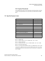
2.9 Specified System Limits . . . . . . . . . . . . . . . . . . . . . . . . . . . . . . . . . . . . . . . . . . . . . . . . . . . . . . . . . . . . . . . .
2.10 Definitions . . . . . . . . . . . . . . . . . . . . . . . . . . . . . . . . . . . . . . . . . . . . . . . . . . . . . . . . . . . . . . . . . . . . . . . . .
2.10.1 Resource Counter. . . . . . . . . . . . . . . . . . . . . . . . . . . . . . . . . . . . . . . . . . . . . . . . . . . . . . . . . . . . . . . .
25
25
25
26
26
26
27
27
28
28
28
29
29
30
30
31
31
31
32
32
33
33
34
34
A31003-C1010-M100-3-7620, 05/2014
HiPath Cordless IP, Administrator Documentation
3
bkTOC.fm
Contents
Nur für den internen Gebrauch
2.10.2 Stream . . . . . . . . . . . . . . . . . . . . . . . . . . . . . . . . . . . . . . . . . . . . . . . . . . . . . . . . . . . . . . . . . . . . . . . .
2.11 Installation Process. . . . . . . . . . . . . . . . . . . . . . . . . . . . . . . . . . . . . . . . . . . . . . . . . . . . . . . . . . . . . . . . . .
2.11.1 Initial Setup of Media Gateway . . . . . . . . . . . . . . . . . . . . . . . . . . . . . . . . . . . . . . . . . . . . . . . . . . . . .
2.11.2 Update Concepts. . . . . . . . . . . . . . . . . . . . . . . . . . . . . . . . . . . . . . . . . . . . . . . . . . . . . . . . . . . . . . . .
2.11.2.1 Update from V1R4 . . . . . . . . . . . . . . . . . . . . . . . . . . . . . . . . . . . . . . . . . . . . . . . . . . . . . . . . . . .
2.11.3 Licensing . . . . . . . . . . . . . . . . . . . . . . . . . . . . . . . . . . . . . . . . . . . . . . . . . . . . . . . . . . . . . . . . . . . . . .
2.11.4 Process Names . . . . . . . . . . . . . . . . . . . . . . . . . . . . . . . . . . . . . . . . . . . . . . . . . . . . . . . . . . . . . . . . .
2.12 Details to System Entities . . . . . . . . . . . . . . . . . . . . . . . . . . . . . . . . . . . . . . . . . . . . . . . . . . . . . . . . . . . . .
2.12.1 Media Gateway-IWU . . . . . . . . . . . . . . . . . . . . . . . . . . . . . . . . . . . . . . . . . . . . . . . . . . . . . . . . . . . . .
2.12.2 Media Gateway . . . . . . . . . . . . . . . . . . . . . . . . . . . . . . . . . . . . . . . . . . . . . . . . . . . . . . . . . . . . . . . . .
2.12.2.1 Synchronization between MGW inside the same Site . . . . . . . . . . . . . . . . . . . . . . . . . . . . . . . .
2.12.2.2 Limitation of calls at 1588 master base . . . . . . . . . . . . . . . . . . . . . . . . . . . . . . . . . . . . . . . . . . .
2.12.2.3 Max. no. of BSIP per MGW . . . . . . . . . . . . . . . . . . . . . . . . . . . . . . . . . . . . . . . . . . . . . . . . . . . .
2.12.3 Requirements . . . . . . . . . . . . . . . . . . . . . . . . . . . . . . . . . . . . . . . . . . . . . . . . . . . . . . . . . . . . . . . . . .
2.12.4 Network Communication Concept . . . . . . . . . . . . . . . . . . . . . . . . . . . . . . . . . . . . . . . . . . . . . . . . . . .
2.12.4.1 General Requirement: VPN . . . . . . . . . . . . . . . . . . . . . . . . . . . . . . . . . . . . . . . . . . . . . . . . . . . .
2.12.4.2 Communication Concept . . . . . . . . . . . . . . . . . . . . . . . . . . . . . . . . . . . . . . . . . . . . . . . . . . . . . .
2.12.5 Dynamic Configuration Changes. . . . . . . . . . . . . . . . . . . . . . . . . . . . . . . . . . . . . . . . . . . . . . . . . . . .
34
36
36
37
37
37
38
38
38
38
39
41
41
42
42
42
42
43
3 Quick Start. . . . . . . . . . . . . . . . . . . . . . . . . . . . . . . . . . . . . . . . . . . . . . . . . . . . . . . . . . . . . . . . . . . . . . . . . . . 45
3.1 Quick Start - Small Solution, Server Solution . . . . . . . . . . . . . . . . . . . . . . . . . . . . . . . . . . . . . . . . . . . . . . . 45
3.1.1 Quick start overview . . . . . . . . . . . . . . . . . . . . . . . . . . . . . . . . . . . . . . . . . . . . . . . . . . . . . . . . . . . . . . 45
3.1.2 Example Configuration . . . . . . . . . . . . . . . . . . . . . . . . . . . . . . . . . . . . . . . . . . . . . . . . . . . . . . . . . . . . 46
3.1.3 Prepare and Connect Hardware . . . . . . . . . . . . . . . . . . . . . . . . . . . . . . . . . . . . . . . . . . . . . . . . . . . . . 46
3.1.3.1 HPCIP - BSIP (Small Solution) . . . . . . . . . . . . . . . . . . . . . . . . . . . . . . . . . . . . . . . . . . . . . . . . . . 46
3.1.3.2 HPCIP - Server (Server Solution) . . . . . . . . . . . . . . . . . . . . . . . . . . . . . . . . . . . . . . . . . . . . . . . . 47
3.1.4 Configure BSIP/Server for IWU mode . . . . . . . . . . . . . . . . . . . . . . . . . . . . . . . . . . . . . . . . . . . . . . . . . 47
3.1.4.1 HPCIP - BSIP (Small Solution) . . . . . . . . . . . . . . . . . . . . . . . . . . . . . . . . . . . . . . . . . . . . . . . . . . 47
3.1.4.2 HPCIP - Server (Server Solution) . . . . . . . . . . . . . . . . . . . . . . . . . . . . . . . . . . . . . . . . . . . . . . . . 50
3.1.5 Configuration of VoIP (Infrastructure) network . . . . . . . . . . . . . . . . . . . . . . . . . . . . . . . . . . . . . . . . . . 52
3.1.6 Configuration of DECT network. . . . . . . . . . . . . . . . . . . . . . . . . . . . . . . . . . . . . . . . . . . . . . . . . . . . . . 54
3.1.7 Configuration of users at the PBX . . . . . . . . . . . . . . . . . . . . . . . . . . . . . . . . . . . . . . . . . . . . . . . . . . . . 56
3.1.8 Configuration of users at the BSIP-IWU . . . . . . . . . . . . . . . . . . . . . . . . . . . . . . . . . . . . . . . . . . . . . . . 56
3.1.8.1 Gateway and Group . . . . . . . . . . . . . . . . . . . . . . . . . . . . . . . . . . . . . . . . . . . . . . . . . . . . . . . . . . . 56
3.1.8.2 User . . . . . . . . . . . . . . . . . . . . . . . . . . . . . . . . . . . . . . . . . . . . . . . . . . . . . . . . . . . . . . . . . . . . . . . 58
3.1.9 Configure further BSIP-Only to the system . . . . . . . . . . . . . . . . . . . . . . . . . . . . . . . . . . . . . . . . . . . . . 60
3.1.10 Start system services and register handsets. . . . . . . . . . . . . . . . . . . . . . . . . . . . . . . . . . . . . . . . . . . 63
3.1.10.1 Start system services . . . . . . . . . . . . . . . . . . . . . . . . . . . . . . . . . . . . . . . . . . . . . . . . . . . . . . . . . 63
3.1.10.2 Register handsets . . . . . . . . . . . . . . . . . . . . . . . . . . . . . . . . . . . . . . . . . . . . . . . . . . . . . . . . . . . 64
3.1.11 "Quick Start" Completion . . . . . . . . . . . . . . . . . . . . . . . . . . . . . . . . . . . . . . . . . . . . . . . . . . . . . . . . . . 66
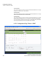
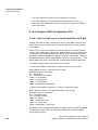
3.2 Quick Start - MGW-IWU System . . . . . . . . . . . . . . . . . . . . . . . . . . . . . . . . . . . . . . . . . . . . . . . . . . . . . . . . 66
3.3 Further steps. . . . . . . . . . . . . . . . . . . . . . . . . . . . . . . . . . . . . . . . . . . . . . . . . . . . . . . . . . . . . . . . . . . . . . . . 66
3.3.1 Radio frequency site survey . . . . . . . . . . . . . . . . . . . . . . . . . . . . . . . . . . . . . . . . . . . . . . . . . . . . . . . . 66
3.3.2 Synchronisation implementation . . . . . . . . . . . . . . . . . . . . . . . . . . . . . . . . . . . . . . . . . . . . . . . . . . . . . 66
4 Configuration reference . . . . . . . . . . . . . . . . . . . . . . . . . . . . . . . . . . . . . . . . . . . . . . . . . . . . . . . . . . . . . . . . 67
4.1 WBM overview IWU . . . . . . . . . . . . . . . . . . . . . . . . . . . . . . . . . . . . . . . . . . . . . . . . . . . . . . . . . . . . . . . . . . 67
4.1.1 Different WBM modes (WBM Users). . . . . . . . . . . . . . . . . . . . . . . . . . . . . . . . . . . . . . . . . . . . . . . . . . 67
4.1.2 Limited Features in WBM mode Unify . . . . . . . . . . . . . . . . . . . . . . . . . . . . . . . . . . . . . . . . . . . . . . . . . 68
4.1.2.1 BSIP-IWU, Server-IWU, MGW-IWU. . . . . . . . . . . . . . . . . . . . . . . . . . . . . . . . . . . . . . . . . . . . . . . 68
4.1.3 Login to WBM . . . . . . . . . . . . . . . . . . . . . . . . . . . . . . . . . . . . . . . . . . . . . . . . . . . . . . . . . . . . . . . . . . . 69
4.1.3.1 Multiple WBM sessions . . . . . . . . . . . . . . . . . . . . . . . . . . . . . . . . . . . . . . . . . . . . . . . . . . . . . . . . 69
4.1.3.2 Login and Password change . . . . . . . . . . . . . . . . . . . . . . . . . . . . . . . . . . . . . . . . . . . . . . . . . . . . 70
4
A31003-C1010-M100-3-7620, 05/2014
HiPath Cordless IP, Administrator Documentation
bkTOC.fm
Nur für den internen Gebrauch
Contents
4.1.3.3 Changing a WBM User's password. . . . . . . . . . . . . . . . . . . . . . . . . . . . . . . . . . . . . . . . . . . . . . . . 70
4.1.4 Configuration Objects . . . . . . . . . . . . . . . . . . . . . . . . . . . . . . . . . . . . . . . . . . . . . . . . . . . . . . . . . . . . . . 71
4.1.5 Configuration Systematic . . . . . . . . . . . . . . . . . . . . . . . . . . . . . . . . . . . . . . . . . . . . . . . . . . . . . . . . . . . 73
4.1.6 Debug Windows . . . . . . . . . . . . . . . . . . . . . . . . . . . . . . . . . . . . . . . . . . . . . . . . . . . . . . . . . . . . . . . . . . 73
4.2 Administration (BSIP-Only) . . . . . . . . . . . . . . . . . . . . . . . . . . . . . . . . . . . . . . . . . . . . . . . . . . . . . . . . . . . . . 75
4.3 Administration (IWU) . . . . . . . . . . . . . . . . . . . . . . . . . . . . . . . . . . . . . . . . . . . . . . . . . . . . . . . . . . . . . . . . . . 78
4.3.1 Frame Configuration . . . . . . . . . . . . . . . . . . . . . . . . . . . . . . . . . . . . . . . . . . . . . . . . . . . . . . . . . . . . . . . 78
4.3.1.1 Button [Restore Config] . . . . . . . . . . . . . . . . . . . . . . . . . . . . . . . . . . . . . . . . . . . . . . . . . . . . . . . . . 78
4.3.1.2 Button [Backup Config] . . . . . . . . . . . . . . . . . . . . . . . . . . . . . . . . . . . . . . . . . . . . . . . . . . . . . . . . . 79
4.3.2 Frame Program Info . . . . . . . . . . . . . . . . . . . . . . . . . . . . . . . . . . . . . . . . . . . . . . . . . . . . . . . . . . . . . . . 81
4.3.2.1 [System Update] . . . . . . . . . . . . . . . . . . . . . . . . . . . . . . . . . . . . . . . . . . . . . . . . . . . . . . . . . . . . . . 82
4.3.2.2 Other options . . . . . . . . . . . . . . . . . . . . . . . . . . . . . . . . . . . . . . . . . . . . . . . . . . . . . . . . . . . . . . . . . 83
4.4 MGWNetwork (MGW) . . . . . . . . . . . . . . . . . . . . . . . . . . . . . . . . . . . . . . . . . . . . . . . . . . . . . . . . . . . . . . . . . 87
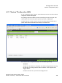
4.5 "Network" Configuration (IWU). . . . . . . . . . . . . . . . . . . . . . . . . . . . . . . . . . . . . . . . . . . . . . . . . . . . . . . . . . . 89
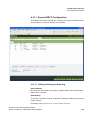
4.5.1 General Network Configuration . . . . . . . . . . . . . . . . . . . . . . . . . . . . . . . . . . . . . . . . . . . . . . . . . . . . . . 89
4.5.2 Local Server and Group Server . . . . . . . . . . . . . . . . . . . . . . . . . . . . . . . . . . . . . . . . . . . . . . . . . . . . . . 93
4.5.2.1 General Server Configuration . . . . . . . . . . . . . . . . . . . . . . . . . . . . . . . . . . . . . . . . . . . . . . . . . . . . 93
4.5.3 Local Server . . . . . . . . . . . . . . . . . . . . . . . . . . . . . . . . . . . . . . . . . . . . . . . . . . . . . . . . . . . . . . . . . . . . . 95
4.5.4 Group Server . . . . . . . . . . . . . . . . . . . . . . . . . . . . . . . . . . . . . . . . . . . . . . . . . . . . . . . . . . . . . . . . . . . . 96
4.6 “SIP” Configuration (IWU) . . . . . . . . . . . . . . . . . . . . . . . . . . . . . . . . . . . . . . . . . . . . . . . . . . . . . . . . . . . . . . 97
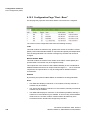
4.6.1 Configuration Page "SIP > General". . . . . . . . . . . . . . . . . . . . . . . . . . . . . . . . . . . . . . . . . . . . . . . . . . . 98
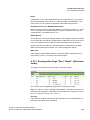
4.6.2 Configuration Page “SIP > SIP Settings” . . . . . . . . . . . . . . . . . . . . . . . . . . . . . . . . . . . . . . . . . . . . . . 100
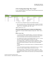
4.6.3 Configuration Page "SIP > Survivability" . . . . . . . . . . . . . . . . . . . . . . . . . . . . . . . . . . . . . . . . . . . . . . 102
4.7 “Media Gateways” Configuration . . . . . . . . . . . . . . . . . . . . . . . . . . . . . . . . . . . . . . . . . . . . . . . . . . . . . . . . 103
4.7.1 Media Gateways (BSIP-IWU and Server-IWU) . . . . . . . . . . . . . . . . . . . . . . . . . . . . . . . . . . . . . . . . . 103
4.7.1.1 Media Gateways > Dect (BSIP-IWU and Server-IWU) . . . . . . . . . . . . . . . . . . . . . . . . . . . . . . . . 104
4.7.1.2 Media Gateways > Dect Network (BSIP-IWU and Server-IWU) . . . . . . . . . . . . . . . . . . . . . . . . . 105
4.7.2 Media Gateways (MGW-IWU) . . . . . . . . . . . . . . . . . . . . . . . . . . . . . . . . . . . . . . . . . . . . . . . . . . . . . . 108
4.7.2.1 General Media Gateway Configuration . . . . . . . . . . . . . . . . . . . . . . . . . . . . . . . . . . . . . . . . . . . . 109
4.7.2.2 WBM > Media Gateways > General . . . . . . . . . . . . . . . . . . . . . . . . . . . . . . . . . . . . . . . . . . . . . . 110
4.7.2.3 WBM > Media Gateways > Dect . . . . . . . . . . . . . . . . . . . . . . . . . . . . . . . . . . . . . . . . . . . . . . . . . 111
4.7.2.4 WBM > Media Gateways > Dect Network . . . . . . . . . . . . . . . . . . . . . . . . . . . . . . . . . . . . . . . . . . 113
4.7.2.5 WBM > Media Gateways > IWU Network . . . . . . . . . . . . . . . . . . . . . . . . . . . . . . . . . . . . . . . . . . 116
4.7.2.6 WBM > Media Gateways > CL Network . . . . . . . . . . . . . . . . . . . . . . . . . . . . . . . . . . . . . . . . . . . 117
4.7.2.7 WBM > Media Gateways > About . . . . . . . . . . . . . . . . . . . . . . . . . . . . . . . . . . . . . . . . . . . . . . . . 118
4.7.2.8 WBM > Media Gateways > VoIP Network. . . . . . . . . . . . . . . . . . . . . . . . . . . . . . . . . . . . . . . . . . 119
4.7.2.9 WBM > Media Gateways > VoIP Gateway . . . . . . . . . . . . . . . . . . . . . . . . . . . . . . . . . . . . . . . . . 120
4.7.2.10 WBM > Media Gateways > Phonebooks. . . . . . . . . . . . . . . . . . . . . . . . . . . . . . . . . . . . . . . . . . 122
4.8 "Group" Configuration (IWU) . . . . . . . . . . . . . . . . . . . . . . . . . . . . . . . . . . . . . . . . . . . . . . . . . . . . . . . . . . . 123
4.8.1 General Group Configuration . . . . . . . . . . . . . . . . . . . . . . . . . . . . . . . . . . . . . . . . . . . . . . . . . . . . . . . 124
4.8.2 Configuration Page “Group” . . . . . . . . . . . . . . . . . . . . . . . . . . . . . . . . . . . . . . . . . . . . . . . . . . . . . . . . 124
4.9 Users Configuration (IWU) . . . . . . . . . . . . . . . . . . . . . . . . . . . . . . . . . . . . . . . . . . . . . . . . . . . . . . . . . . . . . 128
4.9.1 General user configuration . . . . . . . . . . . . . . . . . . . . . . . . . . . . . . . . . . . . . . . . . . . . . . . . . . . . . . . . . 129
4.9.1.1 User Management Options . . . . . . . . . . . . . . . . . . . . . . . . . . . . . . . . . . . . . . . . . . . . . . . . . . . . . 129
4.9.1.2 User Search Options . . . . . . . . . . . . . . . . . . . . . . . . . . . . . . . . . . . . . . . . . . . . . . . . . . . . . . . . . . 132
4.9.2 Configuration Page "User - User" . . . . . . . . . . . . . . . . . . . . . . . . . . . . . . . . . . . . . . . . . . . . . . . . . . . . 133
4.9.3 Configuration Page "User - VoiP" . . . . . . . . . . . . . . . . . . . . . . . . . . . . . . . . . . . . . . . . . . . . . . . . . . . . 135
4.9.4 Configuration Page "User - Dect" . . . . . . . . . . . . . . . . . . . . . . . . . . . . . . . . . . . . . . . . . . . . . . . . . . . . 136
4.10 Dect Configuration (IWU) . . . . . . . . . . . . . . . . . . . . . . . . . . . . . . . . . . . . . . . . . . . . . . . . . . . . . . . . . . . . . 138
4.10.1 General DECT Configuration . . . . . . . . . . . . . . . . . . . . . . . . . . . . . . . . . . . . . . . . . . . . . . . . . . . . . . 139
4.10.1.1 Adding, Deleting and Scanning . . . . . . . . . . . . . . . . . . . . . . . . . . . . . . . . . . . . . . . . . . . . . . . . . 139
4.10.2 Configuration Page "Dect - Base". . . . . . . . . . . . . . . . . . . . . . . . . . . . . . . . . . . . . . . . . . . . . . . . . . . 142
A31003-C1010-M100-3-7620, 05/2014
HiPath Cordless IP, Administrator Documentation
5
bkTOC.fm
Contents
Nur für den internen Gebrauch
4.10.3 Configuration Page "Dect - Radio" (Advanced mode). . . . . . . . . . . . . . . . . . . . . . . . . . . . . . . . . . .
4.10.4 Configuration Page "Dect - Sync" . . . . . . . . . . . . . . . . . . . . . . . . . . . . . . . . . . . . . . . . . . . . . . . . . .
4.10.5 Configuration Page "Dect - ARI" . . . . . . . . . . . . . . . . . . . . . . . . . . . . . . . . . . . . . . . . . . . . . . . . . . .
4.10.6 Configuration Page "Dect - Call" (Advanced mode) . . . . . . . . . . . . . . . . . . . . . . . . . . . . . . . . . . . .
4.10.7 Configuration Page "Dect - About" . . . . . . . . . . . . . . . . . . . . . . . . . . . . . . . . . . . . . . . . . . . . . . . . .
4.10.8 Configuration Page "Dect - Debug" (Advanced mode) . . . . . . . . . . . . . . . . . . . . . . . . . . . . . . . . . .
4.11 Debugging Configuration (IWU) . . . . . . . . . . . . . . . . . . . . . . . . . . . . . . . . . . . . . . . . . . . . . . . . . . . . . . .
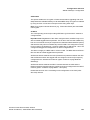
4.12 "Status" Configuration (IWU) . . . . . . . . . . . . . . . . . . . . . . . . . . . . . . . . . . . . . . . . . . . . . . . . . . . . . . . . .
4.12.1 General Status Information . . . . . . . . . . . . . . . . . . . . . . . . . . . . . . . . . . . . . . . . . . . . . . . . . . . . . . .
4.12.2 Configuration Pages "Status > User Status and User Mibs" . . . . . . . . . . . . . . . . . . . . . . . . . . . . . .
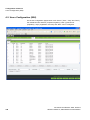
4.12.2.1 Status Search Options . . . . . . . . . . . . . . . . . . . . . . . . . . . . . . . . . . . . . . . . . . . . . . . . . . . . . . .
4.12.2.2 Configuration Page “Status > User Status” . . . . . . . . . . . . . . . . . . . . . . . . . . . . . . . . . . . . . . .
4.12.2.3 Configuration Page "Status > User Mibs" . . . . . . . . . . . . . . . . . . . . . . . . . . . . . . . . . . . . . . . .
4.12.3 Pages "MGW Status > MGW Mibs" (MGW-IWU only) . . . . . . . . . . . . . . . . . . . . . . . . . . . . . . . . . .
4.12.3.1 Options at Lower Frame. . . . . . . . . . . . . . . . . . . . . . . . . . . . . . . . . . . . . . . . . . . . . . . . . . . . . .
4.12.3.2 Configuration Page "Status > MGW Status" . . . . . . . . . . . . . . . . . . . . . . . . . . . . . . . . . . . . . .
4.12.3.3 Configuration Page "Status > MGW Mibs". . . . . . . . . . . . . . . . . . . . . . . . . . . . . . . . . . . . . . . .
4.12.4 Pages "Base Status, -Mibs, -1588, -RSSI" . . . . . . . . . . . . . . . . . . . . . . . . . . . . . . . . . . . . . . . . . . .
4.12.4.1 Options at Lower Frame. . . . . . . . . . . . . . . . . . . . . . . . . . . . . . . . . . . . . . . . . . . . . . . . . . . . . .
4.12.4.2 Page “Base Status” . . . . . . . . . . . . . . . . . . . . . . . . . . . . . . . . . . . . . . . . . . . . . . . . . . . . . . . . .
4.12.4.3 Page “Base Mibs”. . . . . . . . . . . . . . . . . . . . . . . . . . . . . . . . . . . . . . . . . . . . . . . . . . . . . . . . . . .
4.12.4.4 Page “Base 1588” . . . . . . . . . . . . . . . . . . . . . . . . . . . . . . . . . . . . . . . . . . . . . . . . . . . . . . . . . .
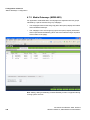
4.12.5 Configuration Page "Status > RSSI" . . . . . . . . . . . . . . . . . . . . . . . . . . . . . . . . . . . . . . . . . . . . . . . .
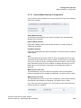
4.13 "System" Configuration (IWU). . . . . . . . . . . . . . . . . . . . . . . . . . . . . . . . . . . . . . . . . . . . . . . . . . . . . . . . .
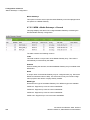
4.14 “CLC” Configuration (Server-IWU, MGW-IWU) . . . . . . . . . . . . . . . . . . . . . . . . . . . . . . . . . . . . . . . . . . .
143
145
148
150
151
153
154
159
160
161
161
163
165
167
167
167
170
173
173
173
175
178
180
183
185
5 Feature Descriptions . . . . . . . . . . . . . . . . . . . . . . . . . . . . . . . . . . . . . . . . . . . . . . . . . . . . . . . . . . . . . . . . . 187
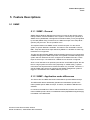
5.1 SNMP . . . . . . . . . . . . . . . . . . . . . . . . . . . . . . . . . . . . . . . . . . . . . . . . . . . . . . . . . . . . . . . . . . . . . . . . . . . . 187
5.1.1 SNMP - General . . . . . . . . . . . . . . . . . . . . . . . . . . . . . . . . . . . . . . . . . . . . . . . . . . . . . . . . . . . . . . . . 187
5.1.2 SNMP - Application mode differences. . . . . . . . . . . . . . . . . . . . . . . . . . . . . . . . . . . . . . . . . . . . . . . . 187
5.1.3 SNMP Tree View (all IWU modes) . . . . . . . . . . . . . . . . . . . . . . . . . . . . . . . . . . . . . . . . . . . . . . . . . . 188
5.1.4 SNMP MIB Tree (all IWU modes, {Root-OID}.1) . . . . . . . . . . . . . . . . . . . . . . . . . . . . . . . . . . . . . . . . 189
5.1.4.1 bsipStatistics-Version ({Root-OID}.1.1.1). . . . . . . . . . . . . . . . . . . . . . . . . . . . . . . . . . . . . . . . . . 189
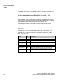
5.1.4.2 bsipStatistics-nn ({Root-OID}.1.1.n (n=2 … 14)) . . . . . . . . . . . . . . . . . . . . . . . . . . . . . . . . . . . . 189
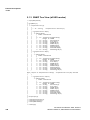
5.1.5 SNMP Trap Tree (all IWU modes, {Root-OID}.2) . . . . . . . . . . . . . . . . . . . . . . . . . . . . . . . . . . . . . . . 190
5.1.5.1 trBsipOnlineState ({Root-OID}.2.1) . . . . . . . . . . . . . . . . . . . . . . . . . . . . . . . . . . . . . . . . . . . . . . 190
5.1.5.2 TR_BSIP_SyncState ({Root-OID}.2.2). . . . . . . . . . . . . . . . . . . . . . . . . . . . . . . . . . . . . . . . . . . . 190
5.1.5.3 TR_10_OVL100 ({Root-OID}.2.3) . . . . . . . . . . . . . . . . . . . . . . . . . . . . . . . . . . . . . . . . . . . . . . . 191
5.1.6 SNMP Tree View (MGW-IWU mode) . . . . . . . . . . . . . . . . . . . . . . . . . . . . . . . . . . . . . . . . . . . . . . . . 192
5.1.7 SNMP MIB Tree (MGW-IWU mode, {Root-OID}.1) . . . . . . . . . . . . . . . . . . . . . . . . . . . . . . . . . . . . . . 193
5.1.7.1 bsipStatistics-Version ({Root-OID}.1.1.1). . . . . . . . . . . . . . . . . . . . . . . . . . . . . . . . . . . . . . . . . . 193
5.1.7.2 bsipStatistics-MgwIndex ({Root-OID}.1.1.2). . . . . . . . . . . . . . . . . . . . . . . . . . . . . . . . . . . . . . . . 193
5.1.7.3 bsipStatistics-nn ({Root-OID}.1.1.n (n=2 … 14)) . . . . . . . . . . . . . . . . . . . . . . . . . . . . . . . . . . . . 193
5.1.8 SNMP MIB Tree (MGW-IWU mode, {Root-OID}.3) . . . . . . . . . . . . . . . . . . . . . . . . . . . . . . . . . . . . . . 193
5.1.8.1 mgwStatistics-Version ({Root-OID}.3.1.1) . . . . . . . . . . . . . . . . . . . . . . . . . . . . . . . . . . . . . . . . . 193
5.1.8.2 mgwStatistics-nn ({Root-OID}.3.1.n (n=2 … 14)) . . . . . . . . . . . . . . . . . . . . . . . . . . . . . . . . . . . . 194
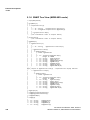
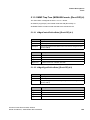
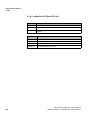
5.1.9 SNMP Trap Tree (MGW-IWU mode, {Root-OID}.4) . . . . . . . . . . . . . . . . . . . . . . . . . . . . . . . . . . . . . 195
5.1.9.1 trMgwControlOnlineState ({Root-OID}.4.1) . . . . . . . . . . . . . . . . . . . . . . . . . . . . . . . . . . . . . . . . 195
5.1.9.2 trMgwSignalOnlineState ({Root-OID}.4.2) . . . . . . . . . . . . . . . . . . . . . . . . . . . . . . . . . . . . . . . . . 195
5.1.9.3 trMgwOvl100 ({Root-OID}.4.3) . . . . . . . . . . . . . . . . . . . . . . . . . . . . . . . . . . . . . . . . . . . . . . . . . . 196
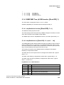
5.2 DHCP . . . . . . . . . . . . . . . . . . . . . . . . . . . . . . . . . . . . . . . . . . . . . . . . . . . . . . . . . . . . . . . . . . . . . . . . . . . . 197
5.2.1 Implementation Detail for Deactivated DHCP . . . . . . . . . . . . . . . . . . . . . . . . . . . . . . . . . . . . . . . . . . 197
6
A31003-C1010-M100-3-7620, 05/2014
HiPath Cordless IP, Administrator Documentation
bkTOC.fm
Nur für den internen Gebrauch
Contents
5.2.2 Implementation Detail for Activated DHCP . . . . . . . . . . . . . . . . . . . . . . . . . . . . . . . . . . . . . . . . . . . . .
5.3 Ethernet Synchronization (acc. IEEE1588) . . . . . . . . . . . . . . . . . . . . . . . . . . . . . . . . . . . . . . . . . . . . . . . .
5.3.1 VLAN Configuration Example . . . . . . . . . . . . . . . . . . . . . . . . . . . . . . . . . . . . . . . . . . . . . . . . . . . . . . .
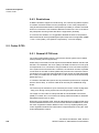
5.4 Support for Different RTP Packet Sizes. . . . . . . . . . . . . . . . . . . . . . . . . . . . . . . . . . . . . . . . . . . . . . . . . . .
5.4.1 Implementation for Incoming Calls towards IP-DECT . . . . . . . . . . . . . . . . . . . . . . . . . . . . . . . . . . . .
5.4.2 Implementation for Outgoing Calls from IP-DECT . . . . . . . . . . . . . . . . . . . . . . . . . . . . . . . . . . . . . . .
5.4.3 Restrictions . . . . . . . . . . . . . . . . . . . . . . . . . . . . . . . . . . . . . . . . . . . . . . . . . . . . . . . . . . . . . . . . . . . . .
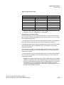
5.5 Codec G.729 . . . . . . . . . . . . . . . . . . . . . . . . . . . . . . . . . . . . . . . . . . . . . . . . . . . . . . . . . . . . . . . . . . . . . . .
5.5.1 General G.729 hints . . . . . . . . . . . . . . . . . . . . . . . . . . . . . . . . . . . . . . . . . . . . . . . . . . . . . . . . . . . . . .
5.5.2 Call Control for G.729 Call Limiting (BSIP-IWU only) . . . . . . . . . . . . . . . . . . . . . . . . . . . . . . . . . . . . .
5.5.3 Support for G.729a SDP . . . . . . . . . . . . . . . . . . . . . . . . . . . . . . . . . . . . . . . . . . . . . . . . . . . . . . . . . . .
5.6 Timezone Support . . . . . . . . . . . . . . . . . . . . . . . . . . . . . . . . . . . . . . . . . . . . . . . . . . . . . . . . . . . . . . . . . . .
5.7 SIP Survivability . . . . . . . . . . . . . . . . . . . . . . . . . . . . . . . . . . . . . . . . . . . . . . . . . . . . . . . . . . . . . . . . . . . . .
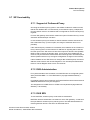
5.7.1 Support of Outbound Proxy . . . . . . . . . . . . . . . . . . . . . . . . . . . . . . . . . . . . . . . . . . . . . . . . . . . . . . . .
5.7.2 DNS Administration . . . . . . . . . . . . . . . . . . . . . . . . . . . . . . . . . . . . . . . . . . . . . . . . . . . . . . . . . . . . . .
5.7.3 DNS SRV . . . . . . . . . . . . . . . . . . . . . . . . . . . . . . . . . . . . . . . . . . . . . . . . . . . . . . . . . . . . . . . . . . . . . .
5.7.4 Penalty Box. . . . . . . . . . . . . . . . . . . . . . . . . . . . . . . . . . . . . . . . . . . . . . . . . . . . . . . . . . . . . . . . . . . . .
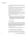
5.7.5 SIP NOTIFY Message in Limited Mode . . . . . . . . . . . . . . . . . . . . . . . . . . . . . . . . . . . . . . . . . . . . . . .
5.7.6 Detection of Failure of SIP Servers . . . . . . . . . . . . . . . . . . . . . . . . . . . . . . . . . . . . . . . . . . . . . . . . . .
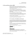
1.0.1 Survivabilty Information . . . . . . . . . . . . . . . . . . . . . . . . . . . . . . . . . . . . . . . . . . . . . . . . . . . . . . . . . . .
5.8 Message Waiting Indication (MWI) . . . . . . . . . . . . . . . . . . . . . . . . . . . . . . . . . . . . . . . . . . . . . . . . . . . . . .
5.8.1 Activation of VoiceMail by Call Forward . . . . . . . . . . . . . . . . . . . . . . . . . . . . . . . . . . . . . . . . . . . . . . .
5.8.1.1 Connecting to the VoiceMail Box. . . . . . . . . . . . . . . . . . . . . . . . . . . . . . . . . . . . . . . . . . . . . . . . .
5.8.1.2 Retrieving the number of messages . . . . . . . . . . . . . . . . . . . . . . . . . . . . . . . . . . . . . . . . . . . . . .
5.8.1.3 MWI LED Activation / Deactivation . . . . . . . . . . . . . . . . . . . . . . . . . . . . . . . . . . . . . . . . . . . . . . .
5.8.1.4 PBX specific MWI functionality . . . . . . . . . . . . . . . . . . . . . . . . . . . . . . . . . . . . . . . . . . . . . . . . . .
5.8.1.5 Technical Background Information . . . . . . . . . . . . . . . . . . . . . . . . . . . . . . . . . . . . . . . . . . . . . . .
5.9 Enhanced Display Information . . . . . . . . . . . . . . . . . . . . . . . . . . . . . . . . . . . . . . . . . . . . . . . . . . . . . . . . . .
5.9.1 Technical Background Information . . . . . . . . . . . . . . . . . . . . . . . . . . . . . . . . . . . . . . . . . . . . . . . . . . .
5.10 Distinctive Ringing . . . . . . . . . . . . . . . . . . . . . . . . . . . . . . . . . . . . . . . . . . . . . . . . . . . . . . . . . . . . . . . . . .
5.10.1 Technical Background Information . . . . . . . . . . . . . . . . . . . . . . . . . . . . . . . . . . . . . . . . . . . . . . . . . .
5.11 "3 Party Call Control" (3PCC) . . . . . . . . . . . . . . . . . . . . . . . . . . . . . . . . . . . . . . . . . . . . . . . . . . . . . . . . .
5.11.1 Technical Background Information . . . . . . . . . . . . . . . . . . . . . . . . . . . . . . . . . . . . . . . . . . . . . . . . . .
5.12 Call Forward (CF). . . . . . . . . . . . . . . . . . . . . . . . . . . . . . . . . . . . . . . . . . . . . . . . . . . . . . . . . . . . . . . . . . .
5.12.1 Technical Background Information . . . . . . . . . . . . . . . . . . . . . . . . . . . . . . . . . . . . . . . . . . . . . . . . . .
5.13 Call Completion (CC) . . . . . . . . . . . . . . . . . . . . . . . . . . . . . . . . . . . . . . . . . . . . . . . . . . . . . . . . . . . . . . . .
5.13.1 Feature description . . . . . . . . . . . . . . . . . . . . . . . . . . . . . . . . . . . . . . . . . . . . . . . . . . . . . . . . . . . . . .
5.13.2 WBM configuration . . . . . . . . . . . . . . . . . . . . . . . . . . . . . . . . . . . . . . . . . . . . . . . . . . . . . . . . . . . . . .
5.13.3 Call description . . . . . . . . . . . . . . . . . . . . . . . . . . . . . . . . . . . . . . . . . . . . . . . . . . . . . . . . . . . . . . . . .
5.14 LDAP Phonebook. . . . . . . . . . . . . . . . . . . . . . . . . . . . . . . . . . . . . . . . . . . . . . . . . . . . . . . . . . . . . . . . . . .
5.14.1 General . . . . . . . . . . . . . . . . . . . . . . . . . . . . . . . . . . . . . . . . . . . . . . . . . . . . . . . . . . . . . . . . . . . . . . .
5.14.2 Configuration of LDAP server . . . . . . . . . . . . . . . . . . . . . . . . . . . . . . . . . . . . . . . . . . . . . . . . . . . . . .
5.14.2.1 Adding a new LDAP Server. . . . . . . . . . . . . . . . . . . . . . . . . . . . . . . . . . . . . . . . . . . . . . . . . . . .
5.14.2.2 Assigning a LDAP Map File. . . . . . . . . . . . . . . . . . . . . . . . . . . . . . . . . . . . . . . . . . . . . . . . . . . .
5.14.2.3 Assigning a LDAP Server to a Group . . . . . . . . . . . . . . . . . . . . . . . . . . . . . . . . . . . . . . . . . . . .
5.14.3 LDAP Map File . . . . . . . . . . . . . . . . . . . . . . . . . . . . . . . . . . . . . . . . . . . . . . . . . . . . . . . . . . . . . . . . .
5.14.4 Sample LDAP Configuration File . . . . . . . . . . . . . . . . . . . . . . . . . . . . . . . . . . . . . . . . . . . . . . . . . . .
5.14.4.1 Built in LDAP server of OpenScapeOffice (OSO MX) . . . . . . . . . . . . . . . . . . . . . . . . . . . . . . . .
5.14.4.2 Sample for Windows Directory service . . . . . . . . . . . . . . . . . . . . . . . . . . . . . . . . . . . . . . . . . . .
5.14.5 LDAP information . . . . . . . . . . . . . . . . . . . . . . . . . . . . . . . . . . . . . . . . . . . . . . . . . . . . . . . . . . . . . . .
5.14.6 Using the LDAP Phonebook . . . . . . . . . . . . . . . . . . . . . . . . . . . . . . . . . . . . . . . . . . . . . . . . . . . . . . .
5.14.6.1 Wildcard search. . . . . . . . . . . . . . . . . . . . . . . . . . . . . . . . . . . . . . . . . . . . . . . . . . . . . . . . . . . . .
A31003-C1010-M100-3-7620, 05/2014
HiPath Cordless IP, Administrator Documentation
198
199
200
201
201
201
202
202
202
204
206
206
207
207
207
207
208
208
209
210
211
211
212
212
213
213
214
214
214
214
215
216
217
218
219
220
220
220
220
222
222
222
223
223
223
223
224
224
226
226
227
227
7
bkTOC.fm
Contents
Nur für den internen Gebrauch
5.14.6.2 Specific pattern search. . . . . . . . . . . . . . . . . . . . . . . . . . . . . . . . . . . . . . . . . . . . . . . . . . . . . . .
5.15 M5T SIP Stack . . . . . . . . . . . . . . . . . . . . . . . . . . . . . . . . . . . . . . . . . . . . . . . . . . . . . . . . . . . . . . . . . . . .
5.16 Call Pickup Group (CPU) . . . . . . . . . . . . . . . . . . . . . . . . . . . . . . . . . . . . . . . . . . . . . . . . . . . . . . . . . . . .
5.17 Call Waiting (CW) . . . . . . . . . . . . . . . . . . . . . . . . . . . . . . . . . . . . . . . . . . . . . . . . . . . . . . . . . . . . . . . . . .
5.18 System Phonebook. . . . . . . . . . . . . . . . . . . . . . . . . . . . . . . . . . . . . . . . . . . . . . . . . . . . . . . . . . . . . . . . .
5.18.1 Sample Phonebook Configuration File . . . . . . . . . . . . . . . . . . . . . . . . . . . . . . . . . . . . . . . . . . . . . .
5.18.2 Using the phonebook. . . . . . . . . . . . . . . . . . . . . . . . . . . . . . . . . . . . . . . . . . . . . . . . . . . . . . . . . . . .
5.19 RTP Negotiation (Part 1) . . . . . . . . . . . . . . . . . . . . . . . . . . . . . . . . . . . . . . . . . . . . . . . . . . . . . . . . . . . .
5.20 Dynamic BSIP Changes . . . . . . . . . . . . . . . . . . . . . . . . . . . . . . . . . . . . . . . . . . . . . . . . . . . . . . . . . . . . .
5.20.1 Dynamic changes ([Edit module]) . . . . . . . . . . . . . . . . . . . . . . . . . . . . . . . . . . . . . . . . . . . . . . . . . .
5.20.2 Firmware Download to a single BSIP ([Fw Download]). . . . . . . . . . . . . . . . . . . . . . . . . . . . . . . . . .
5.20.3 Replacing module ([Replace module]) . . . . . . . . . . . . . . . . . . . . . . . . . . . . . . . . . . . . . . . . . . . . . .
5.20.3.1 Procedures for Replacing a BSIP . . . . . . . . . . . . . . . . . . . . . . . . . . . . . . . . . . . . . . . . . . . . . .
5.20.3.2 Procedures for Exchanging the 1588 Sync Master . . . . . . . . . . . . . . . . . . . . . . . . . . . . . . . . .
5.21 Wan Download . . . . . . . . . . . . . . . . . . . . . . . . . . . . . . . . . . . . . . . . . . . . . . . . . . . . . . . . . . . . . . . . . . . .
5.22 SIP over TCP . . . . . . . . . . . . . . . . . . . . . . . . . . . . . . . . . . . . . . . . . . . . . . . . . . . . . . . . . . . . . . . . . . . . .
5.22.1 Reusing SIP TCP Ports . . . . . . . . . . . . . . . . . . . . . . . . . . . . . . . . . . . . . . . . . . . . . . . . . . . . . . . . . .
5.23 Handset Specific Issues . . . . . . . . . . . . . . . . . . . . . . . . . . . . . . . . . . . . . . . . . . . . . . . . . . . . . . . . . . . . .
5.23.1 Handling of Idle Display. . . . . . . . . . . . . . . . . . . . . . . . . . . . . . . . . . . . . . . . . . . . . . . . . . . . . . . . . .
5.24 System Startup Procedure . . . . . . . . . . . . . . . . . . . . . . . . . . . . . . . . . . . . . . . . . . . . . . . . . . . . . . . . . . .
5.25 Support of Assigned TPUI instead of Default TPUI . . . . . . . . . . . . . . . . . . . . . . . . . . . . . . . . . . . . . . . .
5.25.1 Support of Assigned TPUI instead of Default TPUI. . . . . . . . . . . . . . . . . . . . . . . . . . . . . . . . . . . . .
5.26 Validation for Uniqueness of PMID and TPUI. . . . . . . . . . . . . . . . . . . . . . . . . . . . . . . . . . . . . . . . . . . . .
5.27 User Search Options (V1R5) . . . . . . . . . . . . . . . . . . . . . . . . . . . . . . . . . . . . . . . . . . . . . . . . . . . . . . . . .
5.28 Dect Fundamentals. . . . . . . . . . . . . . . . . . . . . . . . . . . . . . . . . . . . . . . . . . . . . . . . . . . . . . . . . . . . . . . . .
5.28.1 Location Area . . . . . . . . . . . . . . . . . . . . . . . . . . . . . . . . . . . . . . . . . . . . . . . . . . . . . . . . . . . . . . . . .
5.28.2 Requirements for Roaming . . . . . . . . . . . . . . . . . . . . . . . . . . . . . . . . . . . . . . . . . . . . . . . . . . . . . . .
5.28.3 Requirements for Handover . . . . . . . . . . . . . . . . . . . . . . . . . . . . . . . . . . . . . . . . . . . . . . . . . . . . . .
5.28.3.1 Modulo Problem . . . . . . . . . . . . . . . . . . . . . . . . . . . . . . . . . . . . . . . . . . . . . . . . . . . . . . . . . . . .
5.28.4 MGW specific fundamentals for Roaming . . . . . . . . . . . . . . . . . . . . . . . . . . . . . . . . . . . . . . . . . . . .
227
228
228
229
230
231
232
232
232
233
233
233
233
234
235
236
236
236
237
237
238
238
239
239
241
241
243
243
243
244
6 Configuration Techniques . . . . . . . . . . . . . . . . . . . . . . . . . . . . . . . . . . . . . . . . . . . . . . . . . . . . . . . . . . . . . 245
6.1 Free IP Addressing . . . . . . . . . . . . . . . . . . . . . . . . . . . . . . . . . . . . . . . . . . . . . . . . . . . . . . . . . . . . . . . . . . 245
6.2 Adding new BSIP . . . . . . . . . . . . . . . . . . . . . . . . . . . . . . . . . . . . . . . . . . . . . . . . . . . . . . . . . . . . . . . . . . . 245
6.2.1 Scanning of BSIP (V1R1) with IWU (V1R2 and newer) . . . . . . . . . . . . . . . . . . . . . . . . . . . . . . . . . . 246
6.3 Multi-Register (Bulk Registering) of Handsets . . . . . . . . . . . . . . . . . . . . . . . . . . . . . . . . . . . . . . . . . . . . . 247
6.4 Downgrading a HPCIP System. . . . . . . . . . . . . . . . . . . . . . . . . . . . . . . . . . . . . . . . . . . . . . . . . . . . . . . . . 248
6.5 Virtualization of MGW-IWU. . . . . . . . . . . . . . . . . . . . . . . . . . . . . . . . . . . . . . . . . . . . . . . . . . . . . . . . . . . . 248
6.6 Installation of MGW-IWU system . . . . . . . . . . . . . . . . . . . . . . . . . . . . . . . . . . . . . . . . . . . . . . . . . . . . . . . 249
6.6.1 Base installation onto Server (Rx 100 S8). . . . . . . . . . . . . . . . . . . . . . . . . . . . . . . . . . . . . . . . . . . . . 249
6.6.2 Base installation MGW-IWU virtualized onto ESXi . . . . . . . . . . . . . . . . . . . . . . . . . . . . . . . . . . . . . . 250
6.6.2.1 Create virtualized machine environment . . . . . . . . . . . . . . . . . . . . . . . . . . . . . . . . . . . . . . . . . . 250
6.6.3 Installation of MGW-IWU . . . . . . . . . . . . . . . . . . . . . . . . . . . . . . . . . . . . . . . . . . . . . . . . . . . . . . . . . . 252
6.6.4 Installation of MGW . . . . . . . . . . . . . . . . . . . . . . . . . . . . . . . . . . . . . . . . . . . . . . . . . . . . . . . . . . . . . . 252
6.6.5 Initial Setup of MGW-IWU . . . . . . . . . . . . . . . . . . . . . . . . . . . . . . . . . . . . . . . . . . . . . . . . . . . . . . . . . 252
7 Troubleshooting / FAQ . . . . . . . . . . . . . . . . . . . . . . . . . . . . . . . . . . . . . . . . . . . . . . . . . . . . . . . . . . . . . . . . 253
7.1 DECT . . . . . . . . . . . . . . . . . . . . . . . . . . . . . . . . . . . . . . . . . . . . . . . . . . . . . . . . . . . . . . . . . . . . . . . . . . . . 253
7.1.1 BSIP-Only Not Found Using "Scan" . . . . . . . . . . . . . . . . . . . . . . . . . . . . . . . . . . . . . . . . . . . . . . . . . 253
7.1.2 Registration of Handset Not Successful . . . . . . . . . . . . . . . . . . . . . . . . . . . . . . . . . . . . . . . . . . . . . . 253
7.1.3 Idle Display of Handset is Blinking . . . . . . . . . . . . . . . . . . . . . . . . . . . . . . . . . . . . . . . . . . . . . . . . . . 253
7.1.4 Display Message "Netzfehler" / "Out of Order" . . . . . . . . . . . . . . . . . . . . . . . . . . . . . . . . . . . . . . . . . 254
7.1.5 Display Message "No Location" . . . . . . . . . . . . . . . . . . . . . . . . . . . . . . . . . . . . . . . . . . . . . . . . . . . . 254
8
A31003-C1010-M100-3-7620, 05/2014
HiPath Cordless IP, Administrator Documentation
bkTOC.fm
Nur für den internen Gebrauch
Contents
7.1.6 Display Message "No Roaming" . . . . . . . . . . . . . . . . . . . . . . . . . . . . . . . . . . . . . . . . . . . . . . . . . . . . . 254
7.1.7 Display Message "User deactivated" . . . . . . . . . . . . . . . . . . . . . . . . . . . . . . . . . . . . . . . . . . . . . . . . . 254
7.1.8 Display Message "Roaming Overload" . . . . . . . . . . . . . . . . . . . . . . . . . . . . . . . . . . . . . . . . . . . . . . . . 254
8 Appendix. . . . . . . . . . . . . . . . . . . . . . . . . . . . . . . . . . . . . . . . . . . . . . . . . . . . . . . . . . . . . . . . . . . . . . . . . . .
8.1 Configuration Hints for Web Browser. . . . . . . . . . . . . . . . . . . . . . . . . . . . . . . . . . . . . . . . . . . . . . . . . . . . .
8.1.1 Mozilla Firefox. . . . . . . . . . . . . . . . . . . . . . . . . . . . . . . . . . . . . . . . . . . . . . . . . . . . . . . . . . . . . . . . . . .
8.1.2 Microsoft Internet Explorer . . . . . . . . . . . . . . . . . . . . . . . . . . . . . . . . . . . . . . . . . . . . . . . . . . . . . . . . .
8.2 LED States . . . . . . . . . . . . . . . . . . . . . . . . . . . . . . . . . . . . . . . . . . . . . . . . . . . . . . . . . . . . . . . . . . . . . . . . .
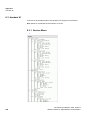
8.3 Handset UI . . . . . . . . . . . . . . . . . . . . . . . . . . . . . . . . . . . . . . . . . . . . . . . . . . . . . . . . . . . . . . . . . . . . . . . . .
8.3.1 Service Menu . . . . . . . . . . . . . . . . . . . . . . . . . . . . . . . . . . . . . . . . . . . . . . . . . . . . . . . . . . . . . . . . . . .
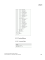
8.3.2 Context Menus . . . . . . . . . . . . . . . . . . . . . . . . . . . . . . . . . . . . . . . . . . . . . . . . . . . . . . . . . . . . . . . . . .
8.3.2.1 Connected State . . . . . . . . . . . . . . . . . . . . . . . . . . . . . . . . . . . . . . . . . . . . . . . . . . . . . . . . . . . . .
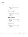
8.3.2.2 Holding State . . . . . . . . . . . . . . . . . . . . . . . . . . . . . . . . . . . . . . . . . . . . . . . . . . . . . . . . . . . . . . . .
8.3.2.3 Call Waiting . . . . . . . . . . . . . . . . . . . . . . . . . . . . . . . . . . . . . . . . . . . . . . . . . . . . . . . . . . . . . . . . .
8.3.2.4 Call Completion . . . . . . . . . . . . . . . . . . . . . . . . . . . . . . . . . . . . . . . . . . . . . . . . . . . . . . . . . . . . . .
8.3.2.5 Pickup Call. . . . . . . . . . . . . . . . . . . . . . . . . . . . . . . . . . . . . . . . . . . . . . . . . . . . . . . . . . . . . . . . . .
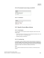
8.3.2.6 Phonebook Access during Local HOLD . . . . . . . . . . . . . . . . . . . . . . . . . . . . . . . . . . . . . . . . . . .
8.3.2.7 Conference . . . . . . . . . . . . . . . . . . . . . . . . . . . . . . . . . . . . . . . . . . . . . . . . . . . . . . . . . . . . . . . . .
8.3.3 Specific Service Menu Actions . . . . . . . . . . . . . . . . . . . . . . . . . . . . . . . . . . . . . . . . . . . . . . . . . . . . . .
8.3.3.1 Set Defaults . . . . . . . . . . . . . . . . . . . . . . . . . . . . . . . . . . . . . . . . . . . . . . . . . . . . . . . . . . . . . . . . .
8.3.3.2 Conferencing . . . . . . . . . . . . . . . . . . . . . . . . . . . . . . . . . . . . . . . . . . . . . . . . . . . . . . . . . . . . . . . .
8.4 System tones . . . . . . . . . . . . . . . . . . . . . . . . . . . . . . . . . . . . . . . . . . . . . . . . . . . . . . . . . . . . . . . . . . . . . . .
8.4.1 Dial tone . . . . . . . . . . . . . . . . . . . . . . . . . . . . . . . . . . . . . . . . . . . . . . . . . . . . . . . . . . . . . . . . . . . . . . .
8.4.2 Calling tone . . . . . . . . . . . . . . . . . . . . . . . . . . . . . . . . . . . . . . . . . . . . . . . . . . . . . . . . . . . . . . . . . . . . .
8.4.3 Busy tone . . . . . . . . . . . . . . . . . . . . . . . . . . . . . . . . . . . . . . . . . . . . . . . . . . . . . . . . . . . . . . . . . . . . . .
8.4.4 Call waiting tone . . . . . . . . . . . . . . . . . . . . . . . . . . . . . . . . . . . . . . . . . . . . . . . . . . . . . . . . . . . . . . . . .
8.5 Key mappings for Handset menus . . . . . . . . . . . . . . . . . . . . . . . . . . . . . . . . . . . . . . . . . . . . . . . . . . . . . . .
8.6 Abbreviations . . . . . . . . . . . . . . . . . . . . . . . . . . . . . . . . . . . . . . . . . . . . . . . . . . . . . . . . . . . . . . . . . . . . . . .
8.7 Acronyms . . . . . . . . . . . . . . . . . . . . . . . . . . . . . . . . . . . . . . . . . . . . . . . . . . . . . . . . . . . . . . . . . . . . . . . . . .
255
255
255
255
257
258
258
259
259
260
260
260
260
261
261
261
261
261
262
262
262
263
263
264
265
266
Index . . . . . . . . . . . . . . . . . . . . . . . . . . . . . . . . . . . . . . . . . . . . . . . . . . . . . . . . . . . . . . . . . . . . . . . . . . . . . . . . 267
A31003-C1010-M100-3-7620, 05/2014
HiPath Cordless IP, Administrator Documentation
9
c05_ikon.fm
Introduction
Scope
1 Introduction
1.1 Scope
This document describes all different kinds of the HiPath Cordless IP System:
•
HPCIP - Small Solution
•
HPCIP - Server Solution
•
HPCIP - Large Solution
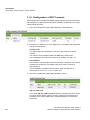
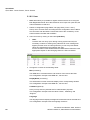
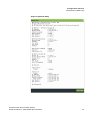
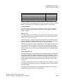
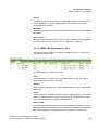
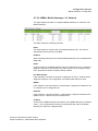
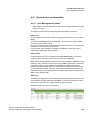
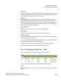
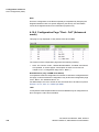
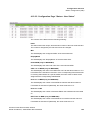
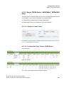
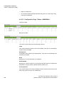
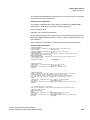
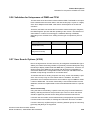
1.1.1 HPCIP Solution Overview
10
Solution Type
No. of
BSIP1
No. of Description
HCIP
Server
Small Solution
1...10
n/a
System components:
- One to 10 pieces of base stations (BSIP1)
Operation modes:
- One base station (BSIP1) running in BSIP-IWU
mode
- All others base stations (BSIP1) running in BSIPonly mode
Server Solution 1...60
1
System components:
- One to 60 pieces of base stations (BSIP1)
- One HiPath Cordless IP Server (HCIP Server)
Operation modes:
- One HiPath Cordless IP Server (HCIP Server)
running in HCIP Server mode (= Management
Server mode + Media Server mode)
- All base stations (BSIP1) running in BSIP-only
mode
Large Solution
2...100 System components:
- One to 3000 pieces of base stations (BSIP1)
- Two to 100 HiPath Cordless IP Server (HCIP
Server)
Operation modes:
- One HiPath Cordless IP Server running in HCIP
Management Server mode
- One to 100 HiPath Cordless IP Server running in
HCIP Media Server mode
- All base stations (BSIP1) running in BSIP-only
mode
1...3000
A31003-C1010-M100-3-76A9, 05/2014
HiPath Cordless IP, Administrator Documentation
c05_ikon.fm
Introduction
Terminology
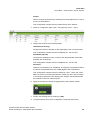
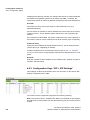
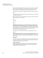
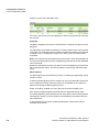
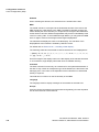
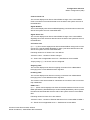
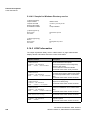
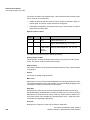
1.1.2 Different Wording Conventions
There are two different wording schemes which describe the components or
functionalities of the HiPath Cordless Ip System.
•A new wording scheme (mainly targeted on marketing issues) and
•An old wording scheme (focuses on technical issues and current WBM wording).
This documentation uses the old wording scheme (since most WBM elements are
already implemented using the old scheme).
The following table depicts the mapping between the new and the old scheme.
New wording scheme (“marketing”)
Old wording scheme (“technical”)
Small Solution
Small Solution
Server Solution
Server Solution
Large Solution
HPCIP - Media Gateway-IWU Solution
HCIP Server mode (Management Server Server-IWU
mode + Media Server mode)
HCIP Management Server mode
MGW-IWU (Server running in Media
Gateway-IWU mode)
HCIP Media Server mode
MGW (Server running in Media Gateway
mode)
BSIP-only mode
BSIP-only mode
BSIP-IWU mode
BSIP-IWU mode
Unless otherwise noted, the instructions in this document refer to all three
solutions.
1.2 Terminology
The terms "Voip gateway" and "PBX" are used as a synonym for the supported
communication servers OpenScape Office MX (OSO MX), HiPath 3000, HiPath
4000 and OpenScape Voice (OSV).
The term BSIP-Only is used as a synonym for a BSIP1 which is not running the
HiPath Cordless IP Server Software.
Therefore the term BSIP-IWU is used as a synonym for a BSIP1 which is
running the HiPath Cordless IP Server Software (IWU).
The term "HPCIP-IWU" or short "IWU" is used as a synonym for the Inter
Working Unit process of the HPCIP system. The IWU may physically run on a
BSIP (BSIP-IWU), a Rx 100 S8 (Server-IWU or MGW-IWU) or virtualized on an
ESX session as Media Gateway-IWU (MGW-IWU).
A31003-C1010-M100-3-76A9, 05/2014
HiPath Cordless IP, Administrator Documentation
11
c05_ikon.fm
Introduction
Network Concept
1.3 Network Concept
The IP network concept of the HiPath Cordless IP solution System is designed
for the separation into several logical networks:
1. VoIP (Infrastructure) network (Server-IWU and BSIP-IWU application
mode)
Here the existing infrastructure components (default Gateways, DHCP
servers, Time server, DNS server, LDAP servers, SNMP clients,...), the PBX
(the VoIP Gateway) and the BSIP1 or the server which is running the HiPath
Cordless IP Server Software (the Interworking Unit [IWU] between VoIP and
DECT) are located. This network is used for the connection of the IWU to the
IP and VoIP infrastructure of the company LAN.
The factory-default network address is 192.168.2.0 with a netmask of
255.255.255.0.
The preconfigured IP address of the IWU in this network is 192.168.2.1.
2. DECT network (all application modes)
Here all BSIP1 Only Base Stations and the BSIP-IWU or the server running
the HiPath Cordless IP Server Software (IWU) are located. This network is
solely used for the communication between the IWU (BSIP-IWU or ServerIWU) or the Media Gateway (MGW) and the BSIP-Only. No Ethernet Layer3
components e.g. Routers are allowed between components inside this
network.
The factory default network address is 192.168.1.0 with a netmask of
255.255.255.0.
The preconfigured network address of the IWU inside the DECT network is
192.168.1.1 with a netmask of 255.255.255.0.
The IP addresses for this network segment may be - apart from the exceptions in the next chapter - configured freely.
3. Media Gateway IWU network (MGW-IWU and MGW application mode)
This network hosts the communication between the MGW-IWU and its
assigned MGW's as well as the existing infrastructure components (default
Gateways, Time server, DNS server, LDAP servers, SNMP clients, ...), except
the VoIP Gateway, which is hosted in a separate network (Media Gateway
VoIP network).
The factory-default network address is 192.168.2.0 with a netmask of
255.255.255.0.
The preconfigured IP address of the IWU in this network is 192.168.2.1.
4. Media Gateway VoIP network (MGW-IWU and MGW application mode)
12
A31003-C1010-M100-3-76A9, 05/2014
HiPath Cordless IP, Administrator Documentation
c05_ikon.fm
Introduction
Network Concept
This network is solely intended for communication between the Media
Gateways and their assigned Voip Gateways (PBX). By default, this network
is bound to the same IP configuration as the MGW IWU network.
5. Media Gateway CrossLink network (MGW-IWU and MGW application
mode)
This network hosts the communication between Media Gateways mainly for
signaling and DECT Handover communication. By default, this network is
bound to the same IP configuration as the MGW IWU network.
6. BSIP internal networks
For internal communication between the different hardware components of
the BSIP1 there are two further networks configured.
Important: These addresses are fixed and cannot be changed. Keep in mind,
that these addresses may not be used for the VoIP network and the DECT
network. Furthermore no other components which are accessing the IWU or
BSIP-Only may use one of these addresses.
192.168.123.x :
Network between the BSIP1 Local DECT module (.222) and the BSIP1-IWU
(.111).
169.254.222.x.
Network between the two main processors CSP (.1) and MSP (.2) for internal
communication.
Important: All BSIP1 devices must be located inside the same network
segment and therefore MUST NOT be separated by layer 3 routing devices.
Only Layer 2 switches are supported between the BSIPs.
1.3.1 Overview of Reserved Networks
Host IPs 192.168.1.1/24 and 192.168.2.1/24 are used for factory defaults of
BSIP-Only and BSIP-IWU
IP network 192.168.123.0/24 for internal communication between CSP and
DECT Baseband controller (BBC).
IP network 169.254.222.0/24 for internal communication between CSP and MSP.
1.3.2 Requirements
Proper functionality of IP-DECT system depends on the underlying networks the
system is operating on.
A31003-C1010-M100-3-76A9, 05/2014
HiPath Cordless IP, Administrator Documentation
13
c05_ikon.fm
Introduction
Network Concept
For all networks except the DECT network, common requirements for a "Voip
ready" network apply. These networks have to be separated from other traffic by
means of a specific VLAN.
For the DECT network, higher requirements apply depending on the synchronization method used. As a minimum requirement, a separate VLAN with highest
priority (in case of LAN Sync) is required. For details, refer to the next sections.
14
A31003-C1010-M100-3-76A9, 05/2014
HiPath Cordless IP, Administrator Documentation
c05_ikon.fm
Introduction
Synchronization Over Air Concept
1.4 Synchronization Over Air Concept
In contrast to a line based synchronization mechanisms (or a network based
one), synchronization via air requires special requirements.
Synchronization signal
Both synchronization partners are syncing over air. This means that the synchronization signal received by the synchronization client from the synchronization
master has to have specific minimum signal strength.
The theoretical minimum signal strength for the synchronization signal is -85 dB.
The minimum aspired signal strength for the synchronization signal is -75 dB
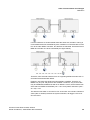
Synchronization topology
For the operation of several synchronized Base Stations several topological
approaches are possible.
1. Star based synchronization topology
This topology uses just one Base station of the whole system as a synchronization Master (Sync Master). All other Base stations which take part at synchronization are working as synchronization Slaves (Sync Slave) and receive their
synchronization signal from the only Sync Master.
2. Chain based synchronization topology
This topology uses just one Base station of the whole system as a synchronization Master (Sync Master). All Base Stations are arranged - in terms of topology
- in a chain.
The second Base Station receives its synchronization signal from the Sync
Master and additionally provides the synchronization signal for the next Base
Station in the chain that is this it serves as well as Sync Slave AND as Sync
Master.
The second BSIP synchronizes to the first BSIP, the third BSIP synchronizes to
the second BSIP, the fourth synchronizes to the third BSIP and so on.
Both topologies may be mixed to achieve large-scale radio coverage.
Important Notes:
•
The topological distance between a "Air Sync Slave" to the topmost "Air Sync
Master" must not be more than 5 hops (including the Master Base and the last
Slave Base) else the "synchronization slip" will be too large.
•
A resynchronization process will be initiated automatically if no call (at the
belonging Base Station) is active.
•
Avoid using a chain topology which is physically arranged as a circle. In such
a scenario, the drift between the first and the last base station may be too
large to ensure proper seamless handover between these two Base Stations.
A31003-C1010-M100-3-76A9, 05/2014
HiPath Cordless IP, Administrator Documentation
15
c05_ikon.fm
Introduction
Synchronization Over Air Concept
16
•
In contrast to a line or Ethernet based synchronization the synchronization
signals is transmitted over air. To achieve efficient signal strength of the
synchronization signal the "radio distance" between two synchronized base
Stations is crucial. This fact has to be considered adequately during the radio
site survey.
•
If a BSIP loses synchronization it tries to resynchronize to its configured
synchronization base station. This process can not start until the last call at
this base station is released and no other calls (at the belonging base station)
are active.
A31003-C1010-M100-3-76A9, 05/2014
HiPath Cordless IP, Administrator Documentation
c05_ikon.fm
Introduction
Synchronization via Ethernet (acc. IEEE 1588)
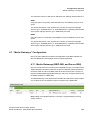
1.5 Synchronization via Ethernet (acc. IEEE 1588)
In contrast to an air based synchronization mechanisms, synchronization via
Ethernet (acc. IEEE1588, PTP Precious Time Protocol) requires less configuration.
The main advantages of synchronization via LAN are:
•
more flexibility in the location of the DECT IP base station - no need to built
synchronization chains as with synchronization via DECT,
•
less DECT IP base stations may be required, because the overlapped area
of DECT IP base station is less
•
configuration of DECT IP systems is simplified, because all DECT IP base
stations can be synchronized to only one synchronization master
On the other hand, great demands are made on the Ethernet characteristics like
symmetry, packet loss, delay, jitter (variance of delay), … Therefore special
requirements regarding the Ethernet components (especially the Ethernet
switches used) have to be considered. Exceeding of limits (especially of jitter) will
lead to loss of synchronization, which will finally lead to a resynchronization
process. During this process the belonging Base Stations are unable to establish
telephony connections.
Synchronization topology
The Synchronization according Ethernet solely uses a star shaped topology.
Maximally one Base Station serves a Synchronization Master (Sync Master), all
other Base Station which participate at the synchronization serve as Synchronization Slaves (Sync Slave).
Resynchronization
The DECT functionality of all BSIP, which are configured as IEEE1588 Sync
Slaves, depends on the availability of the IEEE1588 Sync Master. If the Sync
Master is not functional (e. g not Online due to Ethernet problems …), the DECT
functionality of all IEEE1588 sync slave BSIP will go down. During this time no
telephony is possible.
General requirements on the Ethernet system
A maximum number of three cascaded Ethernet switches are supported between
the Sync Master (SM) and a Sync Slave (SS) BSIP.
Only premium class switches, which fulfill the requirements regarding Ethernet
synchronization according IEEE1588, are supported. A list of supported switches
is documented in the sales information of the HPCIP system.
Synchronization according IEEE1588 may only be used with a project specific
release. Details can be found in the release note of HiPath Cordless IP.
A31003-C1010-M100-3-76A9, 05/2014
HiPath Cordless IP, Administrator Documentation
17
c05_ikon.fm
Introduction
WBM related issues
Usage of VLAN at the BSIP-IWU for Infrastructure and DECT network is
mandatory. All participating switches have to be configured in a way that the
VLAN of the DECT network has to be assigned the highest priority.
Further details regarding Ethernet Synchronization according IEEE1588 may be
found in chapter 1.5, “Synchronization via Ethernet (acc. IEEE 1588)”.
1.6 WBM related issues
1.6.1 Supported Web Browser
The following web browsers are supported:
•
Mozilla Firefox
•
Microsoft Internet Explorer
For details refer to chapter 8.1, “Configuration Hints for Web Browser” as well as
the release notes.
1.6.2 General WBM Issues
•
The following special characters are not allowed inside the configuration
objects for WBM:
“[“, “]”, “%”, ASC (0) - ASC (0x1F)
•
Adding or removing of some configuration objects is only supported if
services are stopped.
•
Configuration and firmware files MUST NOT include spaces in their filenames
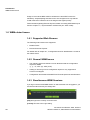
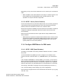
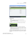
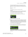
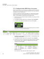
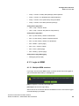
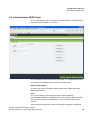
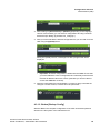
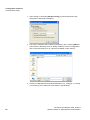
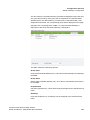
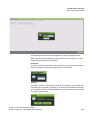
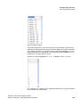
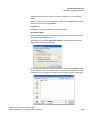
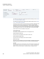
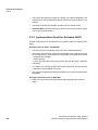
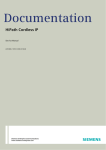
1.6.3 Simultaneous WBM Sessions
If you login onto the same WBM session on which another user is logged on, you
are informed about that by a message box.
[OK] will logout the currently connected user.
[Cancel] Go back to the Login dialog.
18
A31003-C1010-M100-3-76A9, 05/2014
HiPath Cordless IP, Administrator Documentation
c05_ikon.fm
Introduction
WBM related issues
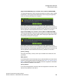
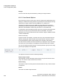
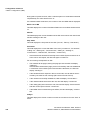
1.6.4 Marking Changed Values
Changed values are marked with a red triangle at the top left corner of the corresponding field. But you have to leave the current field for changes to come in
effect (via TAB key or mouse).
Please keep in mind that changes are not in effect immediately. You have to
•
apply the changes with the [Apply] button and for some changes you have to
•
restart the services or for some changes
•
reboot the IWU
Information which actions have to be taken to take the changes into effect will be
described in the appropriate chapters.
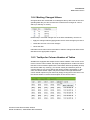
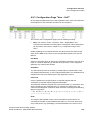
1.6.5 Tooltips for Column Headers of Tables
All tables are equipped with tooltips for the column headers. If the mouse cursor
moves over the column header, the tooltip is displayed which contains the same
text as the column header caption itself. This feature offers the possibility to keep
the column width very small (e.g. for counter values) and therefore place all
columns fitting on one screen without the need of scrolling horizontally. In this
case, the column header caption may be truncated on the right side but the
column header caption may be derived by simply moving the mouse cursor over
the column header to retrieve the description of the current column.
A31003-C1010-M100-3-76A9, 05/2014
HiPath Cordless IP, Administrator Documentation
19
c05_ikon.fm
Introduction
WBM related issues
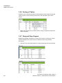
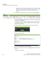
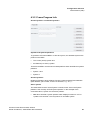
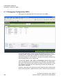
1.6.6 Sorting of Tables
All tables may be sorted (Ascending or Descending) by either double-clicking the
column header or by left clicking of the arrow in the right area of the column
header.
•
Hint: Sort properties are not stored. After a change of pages the original sort
order is restored.
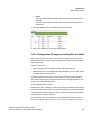
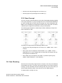
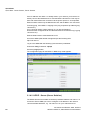
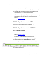
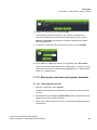
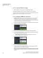
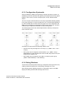
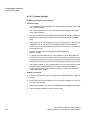
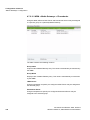
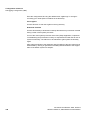
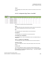
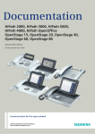
1.6.7 Drag and Drop Support
Besides the standard mechanism of sorting user entries by clicking the column
headers individual user entries may be reordered using a drag and drop
mechanism.
1. Select the user entry that should be moved by pressing the left mouse button.
2. Drag the selected entry to the new designated position.
20
A31003-C1010-M100-3-76A9, 05/2014
HiPath Cordless IP, Administrator Documentation
c05_ikon.fm
Introduction
WBM related issues
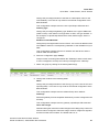
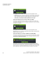
•
Hints:
The entry will be added above the selected entry if the drag direction is
upwards.
The entry will be added below the selected entry if the drag direction is
downwards.
3. Drop the dragged entry by releasing the left mouse button.
4. Save your changes by clicking the [Apply] button.
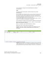
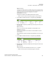
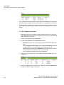
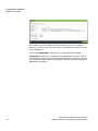
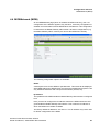
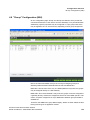
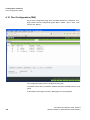
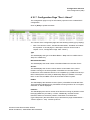
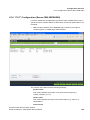
1.6.8 Configuration Changes according Service State
While system services are running, most content of tables are read-only since
editing during running services is not possible without special handling of these
objects at the IWU.
Therefore you have to
•
Stop the system services (Offline mode) to edit these values or
•
Edit the object using a specific functionality (Edit object). You may add, delete
or modify existing object entries.
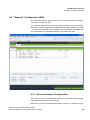
To modify existing entries, select a user row and click the corresponding [Edit
xxx]. Now the entries in the table row are editable. Changes for the selected
objects are locked until the changes are applied using the [Apply] button or are
reverted using the [CANCEL] button.
Hints regarding deletion of users
Please keep in mind, if deleting a user entry the DECT registration is NOT being
removed. Therefore the handset may not be reregistered on the same ARI again.
If a user should be deleted during an active call, the object will NOT be deleted.
A message box will inform about this.
In HPCIP V1R5, a lot of new objects may be modified during running system
services. For details, refer to Section 2.12.5, “Dynamic Configuration Changes”.
A31003-C1010-M100-3-76A9, 05/2014
HiPath Cordless IP, Administrator Documentation
21
c05_ikon.fm
Introduction
Partition concept of BSIP1
1.7 Partition concept of BSIP1
To guarantee a functional BSIP at any time, two bootable systems are implemented at the BSIP1.
A current system and the fallback system. Therefore the BSIP has two different
systems partitions:
System 1 and System 2.
Both system partitions can hold their own configuration (although it is copied
from one partition to the other during a firmware update).
Both partitions store their application mode (BSIP-Only or BSIP-IWU)
A factory reset is always applied to the current system partition. It does not
affect the settings of the other partition.
•
22
Hint: Similar to the BSIP-IWU, the Server-IWU contains the same partition
concept as described above.
A31003-C1010-M100-3-76A9, 05/2014
HiPath Cordless IP, Administrator Documentation
c05_ikon.fm
Introduction
Factory reset of BSIP1
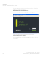
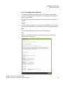
1.8 Factory reset of BSIP1
A Factory Reset (resetting the BSIP1 to its default configuration) may be
performed either by
•
a local login at the WBM of a BSIP-Only using the Factory Reset button or
•
a special "power sequencing" cycle (e.g. if the BSIP WBM is not accessible)
using the ethernet cable at the BSIP.
Both methods are resetting the active partition of a BSIP1 to its factory default
configuration.
The factory reset by “power sequencing” is applied by the following process:
1. Power on the board by plugging the ethernet cable (see note)
2. Wait 5s (3s < wait < 7s)
3. Power off the board by unplugging the ethernet cable
4. Repeat steps 1. - 3. three (3) times
5. Boot BSIP1 to OS
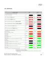
The successful factory reset is indicated by fast red flashing of both LEDs.
•
Note: If you provide power to the board by connecting the ethernet cable
using a PoE Switch power may NOT provided immediately. Due to the stages
of powering up a PoE link defined in 802.3af it may take up to some seconds
until the power is delivered from the switch to the PoE port. Take a look at the
LEDs or the switch status LEDs to see at which point the power is available.
After this procedure, the default configuration parameters will be set.
The default application mode after a reset is BSIP-Only mode.
•
Hint: The factory reset is applied to the currently active partition. It does not
affect the settings of the other partition. But both operation mode settings
(BSIP-Only and BSIP-IWU) of the active partitions are resetted
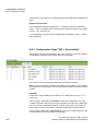
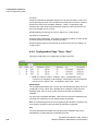
Setting
Value
Operation mode:
BSIP-Only
IP address of VoIP network
192.168.1.1
Access mode
http
User Unify
Username: "Unify", password "1q21q2"
User UnifyAdmin
Username: "UnifyAdmin", password
"1q21q2"
A31003-C1010-M100-3-76A9, 05/2014
HiPath Cordless IP, Administrator Documentation
23
c05_ikon.fm
Introduction
Factory reset of BSIP1
24
Setting
Value
Operation mode:
BSIP-IWU
IP address of VoIP network
192.168.2.1
Access mode
http
User Unify
Username: "Unify", password "1q21q2"
User UnifyAdmin
Username: "UnifyAdmin", password
"1q21q2"
A31003-C1010-M100-3-76A9, 05/2014
HiPath Cordless IP, Administrator Documentation
c05_ikon.fm
V1R5 - Enhancements and Changes
Conceptual Overview (MGW-IWU mode)
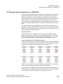
2 V1R5 - Enhancements and Changes
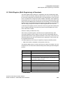
The new version V1R5 introduces some new concepts and features to the HPCIP
system.
•
Enhance number of Basestations from currently 60 to approx. 600 (large
setups).
•
Permit branch setups where a central IWU is located in the central office and
the BSIP are located in several branch offices (sites) separated by Layer2
(Ethernet) or Layer3 links (IP) using LAN or WAN links.
•
Permit changes to the different configuration objects (users, groups, network
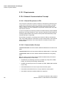
server, PBX, DECT Modules) during running system services.
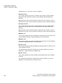
2.1 Conceptual Overview (MGW-IWU mode)
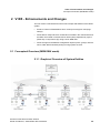
2.1.1 Graphical Overview of System Entities
A31003-C1010-M100-3-76A9, 05/2014
HiPath Cordless IP, Administrator Documentation
25
c05_ikon.fm
V1R5 - Enhancements and Changes
System Entities
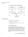
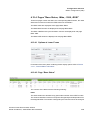
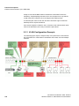
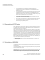
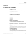
2.1.2 Graphical Overview of Media Gateway
2.2 System Entities
HPCIP V1R5 introduces three new system entity types:
•
Media Gateway-IWU - a new physical entity
•
Media Gateway - a new physical entity
•
Media Gateway Local- a new logical entity for Server-IWU and BSIP-IWU
•
Site - a new logical entity
2.2.1 Media Gateway-IWU
A "Media Gateway-IWU" represents a new physical system entity.
The main task of the IWU process is to interconnect the SIP and Dect call legs.
This doesn't change for the new "Media Gateway-IWU". As opposed to a traditional Server-IWU or BSIP-IWU, the Layer3 communication is now separated by
the network communication between the Media Gateway-IWU and its Media
Gateways (due to the branch concept). Similarly to a V1R4 IWU, most configuration of the whole System is accomplished and centralized at the Media
Gateway-IWU. This enables a centralized configuration concept across all Media
Gateways.
26
A31003-C1010-M100-3-76A9, 05/2014
HiPath Cordless IP, Administrator Documentation
c05_ikon.fm
V1R5 - Enhancements and Changes
System Entities
2.2.2 Media Gateway
A "Media Gateway" represents a new physical system entity and introduces a
new abstraction layer between the Interworking Unit (IWU) and the Basestation
IP (BSIP).
For a traditional IWU (up to V1R4), the IWU process communicated directly with
the BSIP as well as with the SIP PBX. Therefore, SIP connections as well as
DECT connections were terminated at the IWU process.
The "Media Gateway" breaks this media termination scheme (IWU <-> SIP and
IWU <-> BSIP) by inserting the Media Gateway as a new entity between the IWU
and SIP / DECT. Using a Media Gateway, SIP connections are terminated at the
Media Gateway entity and logical Dect communication is also terminated at the
Media Gateway (although DECT connections are terminated physically at the
BSIP). All BSIP at a specific Media Gateway have to be attached directly by a
Layer2 network to the Media Gateway (the same requirements are needed as
described for a present V1R4 Dect network).
To assure consistent system architecture, the Server-IWU as well as the BSIPIWU will be enhanced by the concept of a logical local Media Gateway (Media
Gateway Local). This concept is similar to the local BSIP included in a BSIP-IWU.
•
Hint: Support of BSIP as a hardware platform for MGW is not included in
V1R5.
2.2.2.1 Media Gateway Types
Four different types of Media Gateways are available:
•
Media Gateway 30
•
Media Gateway 60
•
Media Gateway 90
•
Media Gateway 120
The type mainly determines the maximum number of concurrent calls (30, 60, 90
or 120) at the Media Gateway. Furthermore, the hardware type influences the
number of needed resources at the Media Gateway IWU.
Therefore, the hardware on which the different Media Gateway types are running
is the same.
The different Media Gateways types (30, 60, 90 or 120) may be combined to build
a cluster of up to 5 Media Gateways per site. This concept may permit the minimization of needed resource counters at the IWU by using several smaller Media
Gateways at a site instead of one large one. In this case, the number of resource
counters decreases, but the number of needed hardware for the Media
Gateway(s) increases.
A31003-C1010-M100-3-76A9, 05/2014
HiPath Cordless IP, Administrator Documentation
27
c05_ikon.fm
V1R5 - Enhancements and Changes
Dependencies between User, Group, MGW and PBX
Each of this Media Gateway type is able to handle the number of max. concurrent
DECT calls derived from its type definition (30, 60, 90 or 120 Dect calls),
according the following table.
Media Gateway Max.
Type
BSIP
Max. concurrent
Call streams
Max. concurrent Resource
DECT calls
Counter
MGW 30
120
120
30
2
MGW 60
120
120
60
4
MGW 90
120
120
90
6
MGW 120
120
120
120
8
2.2.3 Site
A Site represents a new logical system entity by grouping 1 to 5 physical Media
Gateways by means of a "Site Id".
Between each of this MGW inside the site, Roaming and Internal Handover may
be possible.
Between two sites, only Roaming is possible, but may be disabled by means of
configuration.
All Media Gateways with the same "Site Id" are belonging to the same site. To
assign a MGW to a specific site, this "Site-Id" is used.
2.3 Dependencies between User, Group, MGW and PBX
2.3.1 Traditional Concept
The following figure depicts the relationships between Gateways, Groups and
Users in the traditional concept of HPCIP up to V1R4.
According to the figure above the following relations exist:
28
A31003-C1010-M100-3-76A9, 05/2014
HiPath Cordless IP, Administrator Documentation
c05_ikon.fm
V1R5 - Enhancements and Changes
User Roaming
•
Several users may be assigned to one Group (n:1).
•
Several groups may be assigned to one PBX (n:1).
2.3.2 New Concept
The new concept of V1R5 introduces a new entity of type Media Gateway (MGW)
in the group systematic. A group is assigned to one or several Media Gateways
(In case of a BSIP-IWU or Server-IWU, the groups can only be assigned to the
MGW-Local). A MGW may be assigned one PBX on a per group base. Therefore,
a MGW may be assigned several PBX by using several groups.
The following figure depicts the relationships between Gateways, Groups and
Users of HPCIP in V1R5.
According to the figure above the following relations exist:
•
Several users may be assigned to one Group (n:1). (WBM > User > User >
Groups)
•
Each group may be assigned to several MGW' s (1:n). (WBM > Group >
MediaGW List). In case of a BSIP-IWU or Server-IWU, the groups can only
be assigned to the MGW-Local
•
Each MGW may be assigned to one PBX (1:1) inside a specific group
(WBM > Media Gateways > VoIP Gateway)
2.4 User Roaming
Since the new concept may support branch concepts, a user may roam between
several Sites of a branch. The term user roaming does not only restrict to DECT
roaming. It is also extended to the SIP roaming of the user, since each Site (or a
specific Media Gateway inside a site) may have its own PBX assigned.
To support DECT roaming of a user,
A31003-C1010-M100-3-76A9, 05/2014
HiPath Cordless IP, Administrator Documentation
29
c05_ikon.fm
V1R5 - Enhancements and Changes
DECT Roaming and Handover
•
an appropriate Dect configuration (ARI / FPS) has to be chosen (for details
refer to Section 5.28.4, “MGW specific fundamentals for Roaming”.
•
roaming has to be enabled for a specific MGW by means of configuration at
the HPCIP (Group > MediaGW List)
A user is configured uniquely at the Media Gateway-IWU. To support the SIP
roaming of a user between different PBX, it is necessary that the global user
configuration data is unique across all PBX of all sites. This comprises the MSN,
Username, AuthName as well as the Password.
2.5 DECT Roaming and Handover
The new system concept uses the similar mechanisms of Dect roaming and Dect
handover (Intracell and Intercell handover based on bearer handover) as former
V1R4 versions. This concept has been enhanced by a freely configurable DECT
LAL (Location Area Level) parameter.
Further information may be found in Section 5.28, “Dect Fundamentals”.
2.5.1 Description of former Dect Roaming Concept
Using DECT roaming in the old concept was realized by two different concepts.
1. IWU triggered Dect Roaming
To implement a branch office scenario, IWU triggered "Multi-IWU" roaming by
means of DECT identification entities (ARI) was used. Therefore, several IWU s
had to be configured using the same ARI. The DECT user data had to be configured identically on all IWU's.
For this concept, a geographical separation of DECT base stations between all
sites is necessary due to the same ARI used on several unsynchronized DECT
areas.
As one of the drawbacks, SIP users had to be registered on each IWU at the
specific IWU with an IWU specific Username. To ensure reach ability, PBX centric
group mechanism (e.g. MULAP groups) had to be used to ensure reach ability at
all locations and for the same phone number.
2. Handset triggered Dect Roaming
To implement a branch office scenario, handset triggered Multi-IWU roaming by
means of different DECT registrations of the handset was used. Therefore, each
IWU has to be configured using a different ARI. The DECT user data may be
configured differently on all IWU's.
30
A31003-C1010-M100-3-76A9, 05/2014
HiPath Cordless IP, Administrator Documentation
c05_ikon.fm
V1R5 - Enhancements and Changes
IP Roaming
For this concept, a geographical separation of DECT base stations between all
sites is not necessary (but suggested due to the missing synchronization between
the Dect systems) due to the different ARI.
2.5.2 Description of new Dect Roaming Concept
Since all data of a user is configured centralized at the Media Gateway-IWU, a
separate site specific user configuration is not needed anymore.
The DECT roaming capability is mainly depending on the System ARI used.
Since the new concept introduces a branch concept, roaming has to be configured more specific for the different sites.
To be able to implement a specific roaming scheme, it is vital to understand the
underlying DECT concepts.
2.6 IP Roaming
If an External DECT roaming event (Roaming between different sites) was
detected for a user, this will trigger an immediate SIP roaming event (unregister
from the former PBX and register at the current PBX for the MGW). Therefore, it
is necessary that the global user configuration data is unique across the relating
PBX of all sites. This comprises the MSN, the UserName, the AuthName as well
as the Password.
This doesn't apply for a MGW-Handover event; during an active call, the call
remains connected on the MGW it was established until it will be disconnected.
After the disconnect has finished, the SIP user will be roamed onto the new MGW.
2.7 Network Concept Media Gateway
For a traditional HPCIP system, three different networks have been assigned.
1. VoIP (Infrastructure) network
2. DECT network
3. BSIP1 internal networks (onboard network communication between the
processors of the BSIP)
For the new concept of Media Gateway, the former VoIP (infrastructure) network
is separated into three different networks. (The DECT network as well as the
BSIP1 internal network concept don't change).
A31003-C1010-M100-3-76A9, 05/2014
HiPath Cordless IP, Administrator Documentation
31
c05_ikon.fm
V1R5 - Enhancements and Changes
Feature Concepts
1. "Media Gateway IWU network" (new)
2. "Media Gateway VoIP network" (new)
3. "Media Gateway CrossLink network" (new)
4. "Media Gateway DECT network"
5. "BSIP1 internal networks"
One ip address and a default gateway for the Media Gateway-IWU network may
be configured. Therefore, all other routing towards the Media Gateway-IWU has
to be handled by the default gateway of the Media Gateway-IWU network.
Keep in mind, that for MGW of type 120 inside a site up to 120 connections may
handover between two MGW' s. Therefore, the Router connection between these
MGW' s has to be designed to handle this bandwidth.
Per MGW (independent of type of MGW) max 120 call streams are supported due
to design limits.
If one MGW inside a site is busy with 120 call streams each, no handover to this
MGW will be possible as well as no new calls (either incoming or outgoing) are
possible.
If a site is using several MGW' s, the corresponding DECT networks MUST NOT
be located in the same LAN segment. They have to be separated by different LAN
segments or by means of VLAN separation. Reasons for this segmentation are:
•
Several 1588 master which broadcast 1588 information. -> high broadcast
rate may overflow switches and may be treated as broadcast storms
•
Ease of recognition of 1588 master if only one 1588 master in one LAN
segment
•
Same ip addresses in the DECT network are possible
2.8 Feature Concepts
2.8.1 LDAP and LDAP Phonebook
In the traditional IWU (V1R4), it was possible to configure several LDAP servers
on a per group base. The integrated LDAP client of the IWU was terminated at
the IWU.
In the new concept, also several LDAP Servers are possible. The LDAP Client is
located at the MGW-IWU. A LDAP Server may be assigned to a specific Media
Gateway on a group base.
32
A31003-C1010-M100-3-76A9, 05/2014
HiPath Cordless IP, Administrator Documentation
c05_ikon.fm
V1R5 - Enhancements and Changes
Specified System Limits
2.8.2 System Phonebook
In the traditional IWU (V1R4), only one phonebook / IWU was possible. In the new
concept, several phonebooks (on a group base) are possible (limited to MGWIWU).
2.9 Specified System Limits
Item
Limit V1R5 Step 1
Max. no. of MGW / MGW-IWU
20...100, see 1)
Max. no. of Sites / MGW-IWU
20...100, see 1)
Max. no. of BSIP / Site
up to 568, see 2)
Max. no. of MGW / Site
5
Max. no. of BSIP / MGW
120, see 2)
Max. no. of concurrent calls / MGW 30
30
Max. no. of concurrent calls / MGW 60
60
Max. no. of concurrent calls / MGW 90
90
Max. no. of concurrent calls / MGW 120
120
Max. no. of concurrent calls / Site
600
Max. no. of concurrent calls / MGW-IWU
3000
Max. no. of users / MGW
1200
Max. no. of users / MGW-IWU
20000
Max. no. of PBX / MGW-IWU
100
Max. no. of LDAP server / MGW-IWU
10
Calculated max. values
Max. no. of BSIP / Site:
Max. no. of BSIP / MGW * max. no. of MGW / Site = 120 * 5 = 600
Max. no. of BSIP / MGW-IWU:
Max no. of MGW /MGW-IWU * max. no. of BSIP / MGW = 100 * 120 = 12000
Max. no. of concurrent calls / Site:
Max. no. of concurrent calls / MGW 120 * Max. no. of MGW / Site = 120 * 5 = 600
1) Up to 100, if 1 MGW / Site used, up to 20 if 5 MGW / Site are used. The number
is limited by the Resource Counter which may not exceed 200. For details refer
to next chapter.
A31003-C1010-M100-3-76A9, 05/2014
HiPath Cordless IP, Administrator Documentation
33
c05_ikon.fm
V1R5 - Enhancements and Changes
Definitions
2) Since MGW inside a site are synced via air, each MGW inside this site has to
be configured with up to two virtual External Sync Basestations as well as a
number of CrossLinks which will decrement the number of physical BSIP. For
detail refer to Section 2.12.2.3, “Max. no. of BSIP per MGW”.
2.10 Definitions
2.10.1 Resource Counter
"Resource Counter": At the Media Gateway-IWU, limited resources for the
number of concurrent calls are available. The number of concurrent calls is determined by the Media Gateway Type (30, 60, 90 or 120).
For a Media GW 30, 30 concurrent calls are available. The no. of resource
counter needed is 2.
For a MediaGW 120, 120 concurrent calls are available. The no. of resource
counter needed is 8.
The maximum number of Resource Counters / MediaGW-IWU is limited to 200.
Therefore, the maximum number of MGW' s / MGW-IWU is variable and is limited
to 200 by the following formula:.
(No. of MGW 30 * 2) + (No. of MGW 60 * 4) + (No. of MGW 90 * 6) + (No. of MGW
120 * 8) = 200.
2.10.2 Stream
"Stream" : At the Media Gateway, limited resources for the number of media
streams are available. A stream may be treated as a local connection at a Media
Gateway between a SIP/RTP and DECT call leg.
For a "standard" call at a MGW where the DECT call leg is terminated at a BSIP
attached to the same MGW and the SIP call leg is terminated at a PBX terminated
at the same MGW, one stream is allocated (see figure below).
34
A31003-C1010-M100-3-76A9, 05/2014
HiPath Cordless IP, Administrator Documentation
c05_ikon.fm
V1R5 - Enhancements and Changes
Definitions
If a user handovers to another MGW inside the same site, the DECT call leg is
not terminated at the former MGW anymore, instead it is connected via the Cross
Link to the other MGW. Therefore, two streams are allocated. One at the former
MGW and a further one at the new MGW (see figure below).
Therefore, each external handover from an originating MGW will reduce the no.
of streams at the destination MGW.
Example: 100 calls have handovered from MGW1 to MGW2. Therefore, at
MGW2 only 20 (120-100) streams are available. Therefore, only 20 new calls
may be established at MGW2 as well as on MGW1. Hence, the theoretical sum
of all calls from MGW1 and MGW2 (120 + 120 = 240) will be reduced to (100 +
20 + 20) = 140.
This behavior has taken in account for OVL70 and OVL100 counters. Whatever
value (calls or streams) reaches the system limits first, will trigger a OVL70 or
OVL100 event.
A31003-C1010-M100-3-76A9, 05/2014
HiPath Cordless IP, Administrator Documentation
35
c05_ikon.fm
V1R5 - Enhancements and Changes
Installation Process
2.11 Installation Process
Up to V1R4 two different installation images have been available. One tar image
for the BSIP-IWU and one for the Server-IWU.
For V1R5 this concept is already used. One tar image for the BSIP-IWU and one
for the Server-IWU / MGW-IWU / MGW.
Therefore it is possible to switch the "Application Mode" between "Server-IWU",
"Media Gateway" as well as a "Media Gateway-IWU" similarly to the application
mode switch between a BSIP-Only and a BSIP-IWU.
The Media Gateway-IWU may be installed directly on a supported hardware
platform (Rx 100 S8) or may be installed on a virtualized session on VMware
ESXi5.
Important note: Due to timing issues, virtualization of Server-IWU and Media
Gateway is NOT supported.
The Default Application mode after a reset is "Server-IWU". The IP Addresses of
"Server-IWU", "Media Gateway" and "Media Gateway-IWU" don't differ and
remain to the current IP address of 192.168.2.1. Switching the Application modes
will lead to a factory reset of the destined Application mode after reboot
2.11.1 Initial Setup of Media Gateway
If a Media Gateway has to be setup, only core parameters, which are needed to
communicate with the assigned Media Gateway-IWU, have to be configured
locally via WBM at the Media Gateway site. All further configuration (including the
DECT and SIP configuration) is accomplished centralized at the MGW-IWU.
All DECT Basestations have to be attached and physically available at the configured Ethernet interface.
All BSIP have to be located in the correct partition and firmware version.
Therefore, all BSIP located at the current MGW are updated using the central
update of the MGW or updated locally using the Fw Down button. This Concept
is similar to existing handling of BSIP update/partition sync at Server-IWU or
BSIP-IWU.
If the BSIP are correctly preconfigured and if network connectivity to the Media
Gateway-IWU is confirmed, all further Config is accomplished centrally at the
Media-GW-IWU.
Therefore the MGW tries to contact the MGW-IWU at the configured IP address
/ ports cyclically. If the network connection is established, the MGW-IWU is aware
of the newly attached Media-GW due to the signaled information from the MGW
to MGW-IWU. The MGW may be differentiated by their MAC address (which is
part of the signaled information) as similar to the existing process of differentiating
the BSIP.
36
A31003-C1010-M100-3-76A9, 05/2014
HiPath Cordless IP, Administrator Documentation
c05_ikon.fm
V1R5 - Enhancements and Changes
Installation Process
At the MGW-IWU, the new Media-Gateway may be "scanned" and - if the
signaled information is available at the IWU, the MGW is added to the list of
available MGW' s.
Hint: A MGW is identified uniquely by its MAC address and not by the name.
Therefore, if the HW of MGW has to be replaced, it has to be configured with
same settings. The old MGW (if already existing) has to be detached from the
network. After the new MGW is known by the IWU, it is displayed at the MGWIWU and may be replaced using the same concept as used for replacing BSIP.
2.11.2 Update Concepts
A centralized update of Media Gateways from Media Gateway-IWU is not
supported.
Update of MGW and Basestations is done locally at the corresponding Media
Gateway. Therefore it is necessary to ensure that WBM access from MGW-IWU
to MGW is possible.
An update of basestations only (excluding the MGW itself) may be initiated at the
WBM of MGW-IWU.
2.11.2.1 Update from V1R4
When updating from V1R4 to V1R5 you may run into a licensing issue. When
updating a HPCIP system, the CLC data always is copied from the old to the new
partition. In case of updating from V1R4 to V1R5, CLC data of V1R4 is copied into
the partition of V1R5. Since the default grace period CLC data of V1R4 only
contains 1 Server and 1000 Basestations, (in contrast to 100 Server and 12000
basestations in V1R5), only 1 MGW-IWU and 1000 Basestations will get a valid
license in case of grace period. To break the barrier of 1 Server and 1000
basestations, it is necessary
•
to install a valid license or
•
to install a V1R5 starting from a V1R5 Installation CD (which already contains
the larger grace period values of 100 Server and 12000 basestations).
2.11.3 Licensing
The CLA is running on the MGW-IWU and contains a license controlling the
number of MGW (license object "Server") and the total no. of BSIP (license object
"Basestation"), as nowadays in a Server-IWU. The effort to license the no. of
MGW is realized by using the currently license object "Server". As in current
version V1R4, the license method "First comes, first serves" doesn't change.
A31003-C1010-M100-3-76A9, 05/2014
HiPath Cordless IP, Administrator Documentation
37
c05_ikon.fm
V1R5 - Enhancements and Changes
Details to System Entities
•
The Media Gateway-IWU needs a license.
•
The Server-IWU needs a license.
•
The BSIP-IWU doesn't need a license.
2.11.4 Process Names
Process Name
Description
capisrv
Running on Server-IWU and BSIP-IWU.
iwu
Running on the MGW-IWU, Server-IWU and BSIP-IWU.
capigw
Running on the MGW-IWU; communicates with MGW processes
running on MGW's
mediagw
Running on the MGW; communicates with capigw process running
on MGW-IWU
setupapplic
Running on each of the entities
2.12 Details to System Entities
2.12.1 Media Gateway-IWU
DHCP is not supported at the MGW-IWU since a global concept of DHCP
(including WBM-IWU and MGW) is not possible due to the L3 separation of these
entities.
2.12.2 Media Gateway
To access the BSIP from the Media-GW IWU network for Debugging purposes, it
is possible to activate an option similarly to "MGW as GW" on the present IWU.
Up to 120 BSIP per MGW are supported. Due to the high system load of the BSIP
running as 1588 Master with up to 119 1588 Clients connecting to the 1588
master, a reduction of the max. concurrent calls at the BSIP 1588 master up to 0
calls has to be configured. For details refer to Section 2.12.2.2, “Limitation of calls
at 1588 master base”.
For each MGW, up to 120 "modules" are supported. Besides the module type
"BsIp" for a physical BSIP1, there are other module types (see WBM > Dect >
About > Type) which are required for Inter-Media Gateway Synchronization .
These module types also reduce the maximum number of module resource per
MGW (120). For details refer to Section 2.12.2.3, “Max. no. of BSIP per MGW”.
38
A31003-C1010-M100-3-76A9, 05/2014
HiPath Cordless IP, Administrator Documentation
c05_ikon.fm
V1R5 - Enhancements and Changes
Details to System Entities
Using air Sync for 120 BSIP exclusively is not specified (due to the max number
of hops between Sync Slave and Sync Master which may not be realized by a
high amount of BSIP).
The Firmware management (update) of a MGW as well as the update of the
basestations is only available by the WBM of the MGW itself. It cannot be initiated
by the WBM of MGW-IWU.
DHCP is not supported at the MGW (since several networks have to be configured - which is not a standard option in DHCP).
To prevent potential paging problems of the handsets at a high amount of
basestations (120) the paging area (domains) may be configured separately by
means of the Dect LAL (Location Area Level) parameter. In former versions, each
BSIP built its own paging area (LAL = 39), therefore a page request has to be sent
to each BSIP separately. This lead to a high paging message rate if several
handsets were paged simultaneously which may had overflew the page queues
at the BSIP.
The MGW will not provide specific MIBs or traps. Only OS MIBS are available if
queried directly from the MGW. Specific MGW related MIBS may be provided
centralized by the MGW-IWU.
2.12.2.1 Synchronization between MGW inside the same Site
Besides existing synchronization of Basestations inside a Media Gateway (which
is fundamental for seamless handover), handover between Media Gateway
inside the same site is supported. Hence, a new sync mechanism was introduced
which handles the synchronization between Media Gateways (Inter-Media
Gateway Synchronization).
Since the DECT networks of the Media Gateways have to be separated by VLAN
or separate Ethernet segments, using 1588 as the sync method between Media
Gateways inside a site is not an option. Therefore the concept of Inter-Media
Gateway Synchronization has to be based on Dect synchronization by air.
Background information: As a precondition for air synchronization to work, all
participating Base Stations require Dect specific information about their sync
partners (e.g. beacon, traffic and RSSI information) to handle the movement of
the sync signal. This information (which is being exchanged between IWU and
the BSIP) is transmitted over Ethernet (DECT network). Therefore, this information is IP based and not exchanged by air.
Since the exchange of this information between the Media Gateways inside a site
is necessary, a Virtual Dect Module as well as a CrossLink is defined which
handles the exchange of this information between the Media Gateways. These
module types are solely responsible for exchanging the DECT specific air sync
information which is needed for Inter-Media Gateway Synchronization. Therefore
they are bound to the "MGW IWU network".
A31003-C1010-M100-3-76A9, 05/2014
HiPath Cordless IP, Administrator Documentation
39
c05_ikon.fm
V1R5 - Enhancements and Changes
Details to System Entities
CrossLink module type
The CrossLink modules (CrossLinkSrv and CrossLinkCli) are automatically
created by the IWU for those MGW, which are located inside the same site (Site
Id). For each MGW pair, a CrossLinkSrv and CrossLinkCli are created (there is
no functional difference between CrossLinkSrv and CrossLinkCli).
Virtual Dect Module Type
The virtual Dect module entry is automatically created by the IWU, if one of the
CrossLink sides (CrossLinkSrv or CrossLinkCli) sync type will be switched to from
"n/a" to "ext. master". This will initiate the creation of a module of type "Virt. Base"
on the MGW of the crosslink's opposite side (Destination side). The "Virt. base"
module will be automatically configured by the IWU with a sync setting of "ext.
slave" and a ParkSync which refers to the Index of the Crosslink to the other
MGW.
Please keep in mind, that switching the CrossLinks "sync type" from "n/a" to "ext.
master" requires the configuration of a "ParkSync1" for the CrossLink. This
ParkSync1 entry has to point to a BSIP on the current MGW.
For further details regarding the corresponding options of "Sync" and type (Dect
> Sync > Sync) refer to Section 4.10.4, “Configuration Page "Dect - Sync"”.
For further details regarding the setup of a MGW-IWU system refer to Section 6.6,
“Installation of MGW-IWU system”.
Depending on the Inter-Media gateway synchronization topology (chain or star
based) a Media Gateway may be configured as External Sync Master, External
Sync Slave or a combined External Sync Master and Slave.
1. Example configuration of a MGW which serves as an External Sync Master.
•
One BSIP configured as type: "BsIp", SyncType: "1588 master"
•
All other BSIP are configured as type: "BsIp", SyncType: "1588 slave"
•
One Crosslink configured as type: "CrossLinkSrv ", SyncType: "ext.
master". The ParkSync is derived from the module configured as "1588
master".
2. Example configuration of a MGW which serves as an External Sync Slave.
40
•
One BSIP configured as type: "BsIp", SyncType: "air, 1588 master". The
ParkSync is derived from the Virtual Base module
•
All other BSIP are configured as type: "BsIp", SyncType: "1588 slave"
•
One Crosslink configured as type: "CrossLinkCli ", SyncType: "n/a"
•
One Virtual Base configured as type "Virt. Base", SyncType: "ext. slave".
The ParkSync is derived from the Crosslink module.
A31003-C1010-M100-3-76A9, 05/2014
HiPath Cordless IP, Administrator Documentation
c05_ikon.fm
V1R5 - Enhancements and Changes
Details to System Entities
These combinations may be mixed on MGW's. Therefore it is possible to build a
star based MGW synchronization, a chain based MGW synchronization topology
or mixing both.
2.12.2.2 Limitation of calls at 1588 master base
For up to 60 BSIP1 as 1588 slave configured at one MGW, no call limiting of the
Base acting as 1588 master is necessary under normal circumstances. In case
of synchronization problems, reducing the number of calls for the 1588 master is
suggested.
If more than 60 BSIP1 are configured which are synchronized to the 1588 master,
the number of calls at the BSIP which serves as 1588 master should be reduced
up to 0. In large deployments where several MGW's are synchronized via InterMGW sync, it is suggested to install those BSIP which sync between the MGW in
a isolated environment, e.g. the server room since there is constant temperature
as well as a low number of handsets which may try to located at the basestation
and therefore generate only low Dect load.
2.12.2.3 Max. no. of BSIP per MGW
For each MGW, up to 120 "modules" are supported. Besides the module type
"BsIp" for a physical BSIP1, there are other module types (see WBM > Dect >
About > Type) which are required for Inter-Media Gateway Synchronization .
These module types also reduce the maximum number of module resource per
MGW (120).
Each module of the following type also allocates one module resource.
•
“CrossLinkSrv"
•
"CrossLinkCli"
•
"Virt. Base"
Therefore, the number of max. usable BSIP1 at a MGW depends on the specific
configuration of the Inter-Media Gateway Synchronization at a MGW.
A31003-C1010-M100-3-76A9, 05/2014
HiPath Cordless IP, Administrator Documentation
41
c05_ikon.fm
V1R5 - Enhancements and Changes
Details to System Entities
2.12.3 Requirements
2.12.4 Network Communication Concept
2.12.4.1 General Requirement: VPN
The concept of V1R5 branch offices is based on transparent ip networking and
routing. Since most branch offices are expected to be connected by standard
ADSL or DSL lines with a public ip (which mostly is NAT ted), access to the
network "behind" has to be established using special methods which may differ
from branch to branch.
To ensure transparent ip networking between the Media Gateway-IWU and Media
Gateways, IP tunneling based on Layer 3 (IP) is a requirement. Most popular IP
tunneling implementations are based on VPN (Virtual Private Networks) implemented with ipsec or OpenVPN.
Since similar concepts for connecting branch offices to OSV by VPN already
exist, using VPN should be a well known concept. Please keep in mind, that the
design and implementation of the VPN networks is outside the scope of this
documentation.
2.12.4.2 Communication Concept
1 bidirectional UDP connection between MGW and MGW-IWU for initial control
tasks.
1 bidirectional TCP connection between MGW and MGW-IWU for control tasks.
1 bidirectional TCP connection between MGW and MGW-IWU for signaling
tasks.
Hint: The initial communication between MGW and MGW-IWU (to SCAN the
MGW at the MGW-IWU) is UDP based.
42
•
At MGW-IWU, the following services are needed: http, https, SSH, SNMP,
Syslog, and LDAP (all terminating at MGW-IWU)
•
At MGW, the following services are needed: http, SSH, SNMP (Mibs at MGW
only for OS)
•
Each MGW Network has to be unique inside the whole system.
•
Each MGW VoIP Network has to be unique inside the whole system.
•
Same DECT Networks at different MGW are supported.
A31003-C1010-M100-3-76A9, 05/2014
HiPath Cordless IP, Administrator Documentation
c05_ikon.fm
V1R5 - Enhancements and Changes
Details to System Entities
The MGW-IWU concept requires transparent IP connections between MGW and
MGW-IWU. this is accomplished by using VPN (e.g. Layer 3 ip tunnel via ipsec)
if needed. hardware and concepts of VPN tunnels are not part of the concept and
should rely on already existing strategies at UNIFY.
Each entity of Media Gateway-IWU and Media Gateway solely needs a single
Default gateway which handles all further routing to all other needed networks. In
a further step of specification, it is planned to enable the configuration of separate
ip routes.
2.12.5 Dynamic Configuration Changes
The system concept is designed to allow dynamic changes of settings without the
restart of the system services or rebooting the system - where technically
possible.
Besides the already existing dynamic editing of user and Dect modules, the
concept will be enhanced to support dynamic editing of SIP Gateways, Groups
and Media Gateways by means of a [Edit] button.
Depending of the object which has to be changed, the changes will influence the
affected segment to other objects. As an example, if an ip address of a SIP PBX
is changed, this will influence the affected segment (in this case all users which
are assigned to the PBX by means of a group) in a way, that all user connections
are disconnected and the affected users have to be reregistered at the new ip
address.
The following rules if editing objects apply:
All changes at left part of MGW-IWU > MGW require a reboot of the object for
changes to come in effect.
All changes at MGW-IWU > MGW > Voip Gateway will disconnect active calls at
the belonging Gateway.
Object
Affected Segment / Object / Required Action
MGW > IWU Network
ip settings, reboot of MGW necessary
MGW-IWU > MGW >
Dect Network
Reboot of all MGW necessary (mainly due to Dect sync
issues), all calls (even cross linked calls) are terminated
MGW-IWU > MGW >
CC Network
Not changeable at MGW-IWU
MGW-IWU > MGW >
CC Network
Reboot of all MGW necessary, therefore all CrossLinks are
terminated, current cross linked calls are terminated
MGW-IWU > Network > local ip settings, connections to MGW. Reboot of MGW-IWU
lower frame
necessary, if ip address and /or ports change, all MGW s have
to be configured locally using the MGW WBM to re-establish
connectivity.
A31003-C1010-M100-3-76A9, 05/2014
HiPath Cordless IP, Administrator Documentation
43
c05_ikon.fm
V1R5 - Enhancements and Changes
Details to System Entities
Object
Affected Segment / Object / Required Action
MGW-IWU > Network > No Reboot of MGW-IWU necessary
Table > LDAP Server
MGW-IWU > Network > No Reboot of MGW-IWU necessary
Table > Phonebook
Server
MGW-IWU > Group >
CF and CW
Changes apply for new calls or for existing calls after the next
call establishment
MGW-IWU > Group >
CF and CW
Changes apply for new calls or for existing calls after the next
call establishment
MGW-IWU > Group >
Phonebook Prefix
Changes may apply for established calls
MGW-IWU > Group >
CPU and VM
All calls are disconnected immediately since a reregister is
needed.
If a reboot will be necessary after applying the changes, a message box will
appear offering the possibility to start the reboot ([Yes]) or suppress the reboot
([Cancel]) which will revert to edit mode.
44
A31003-C1010-M100-3-76A9, 05/2014
HiPath Cordless IP, Administrator Documentation
c05_ikon.fm
Quick Start
Quick Start - Small Solution, Server Solution
3 Quick Start
3.1 Quick Start - Small Solution, Server Solution
The quick start chapter describes the initial operation of the HiPath Cordless IP
System V1R5 for a first functional test including the necessary configuration.
In general the configuration steps for both HPCIP platforms (HPCIP - Small
Solution and HPCIP - Server Solution) differ mainly in the initial configuration of
the IWU. Therefore only these steps are documented separately.
The "Quick Start" assumes the availabilty of
•
two BSIP1 or one HPCIP-Server and two BSIP1,
•
a functional PoE network switch, (alternatively a switch and Power
injectors ) and CAT.5 cables
•
a Maintenance PC with administration account and
•
a supported PBX (e.g. OpenScape Office as OSO MX).
The "Quick Start" further assumes, that version V1R5 is already installed on all
used components on the same system partition. Otherwise, update all components to V1R5 first. Corresponding information may be found in Section 4.3.2.1,
“[System Update]”
Please read the corresponding chapter in the detailed manual parts if you need
further information regarding any step of the "Quick Start".
The following conditions apply:
•
For the quick start it is assumed that no VLAN functionality is needed
•
No special DECT or PBX functionality is configured. If applicable, only default
settings are used.
3.1.1 Quick start overview
1. Prepare and connect hardware
2. Configure BSIP1/Server for IWU mode
3. Configuration of VoIP (Infrastructure) Network at IWU
4. Configuration of DECT Network at IWU
5. Configuration of users at the IWU
6. Configuration of users at the PBX
A31003-C1010-M100-3-76A9, 05/2014
HiPath Cordless IP, Administrator Documentation
45
c05_ikon.fm
Quick Start
Quick Start - Small Solution, Server Solution
7. Start system services and register handsets at the IWU
8. Attach and configure further BSIP-Only to the system
3.1.2 Example Configuration
Several settings are needed for configuring a HPCIP system. Inside this quick
start, following settings are used:
Configuration Option
Value
Page Network/Gateways
Network/Gateway: Server IP Address:
192.168.100.1
Network/Gateway: Server IP Netmask:
255.255.255.0
Network/Gateway: Default Gateway:
192.168.100.83
Network/Gateway: NTP Server (Time
Server):
192.168.201.94
Gateway (PBX) - Name:
OpenScape Office MX 3bx
Gateway (PBX) - IP Address:
192.168.201.94
Gateway (PBX) - Netmask:
255.255.255.0
Page DECT
DECT: Server IP Address:
192.168.10.1
DECT: Server IP Netmask:
255.255.255.0
DECT: ARI:
101b2ff5
DECT: PIN:
87654321
Page User
User No. 1: MSN/DisplayName/AuthName/ 761/761/761/1234
Password
User No. 2: MSN/DisplayName/AuthName/ 762/762/762/2345
Password
User No. 3: MSN/DisplayName/AuthName/ 763/763/763/3456
Password
3.1.3 Prepare and Connect Hardware
3.1.3.1 HPCIP - BSIP (Small Solution)
Attach the first BSIP1 to a PoE port of the network switch or via a Power injector
to a standard port of the network switch. Wait about 2 minutes until the LED states
of the BSIP1 change to permanently green and red.
46
A31003-C1010-M100-3-76A9, 05/2014
HiPath Cordless IP, Administrator Documentation
c05_ikon.fm
Quick Start
Quick Start - Small Solution, Server Solution
Meanwhile you may connect the maintenance PC to a switch port via a ethernet
cable.
•
Hint: The BSIP1 must reside inside the same layer 2 network segment. The
devices MUST NOT be separated by layer 3 Routing devices. Only
separation via Layer 2 switches is supported.
3.1.3.2 HPCIP - Server (Server Solution)
Connect the HPCIP-Server (FSC Rx100 S8) to mains, the necessary peripheral
components (monitor and keyboard) and connect the network port using an
Ethernet cable with a Standard or PoE-Port of a network switch.
Boot the Server with the installation CD of the HPCIP Server Software. Install and
configure according the appropriate instructions (which are not part of this
documentation).
Remove the CD and reboot the server again with the newly installed HPCIP
Server software.
•
Hint: Possibly an update to the latest released HPCIP Server Version (V1R4)
should be accomplished. Optionally update twice so that the active system
partition is Partition 2. (Since all newly attached BSIP also come up with
system partition 2 as the active partition).
3.1.4 Configure BSIP/Server for IWU mode
3.1.4.1 HPCIP - BSIP (Small Solution)
The BSIP1 is accessible via its factory default IP address 192.168.1.1 in BSIPOnly mode.
To access the BSIP-Only WBM you have to configure an IP address in the
network 192.168.1.0/255.255.255.0, e.g. 192.168.1.101 on your maintenance
PC.
If the IP address 192.168.1.1 is already used in your network, you first have to
directly connect the maintenance PC and the BSIP1 via ethernet. This may be
done with a direct ethernet connection via the power injector or via a separate
ethernet switch where only the Maintenance PC and the BSIP1 are connected.
Test via ping, if the BSIP1 is replying to the ping requests (ping 192.168.1.1).
If not, check all cabling, switch settings, (e.g VLAN configuration).
Ensure that the configured local IP of the maintenance PC adress is up (e.g ping
192.168.1.101).
A31003-C1010-M100-3-76A9, 05/2014
HiPath Cordless IP, Administrator Documentation
47
c05_ikon.fm
Quick Start
Quick Start - Small Solution, Server Solution
If you don't get replies consider to reset the BSIP to its factory defaults (see
chapter 1.8, “Factory reset of BSIP1”).
Start the Web browser at the Maintenance PC
Access the WBM (Web based management) at the following URL:
http://192.168.1.1
Log in to the WBM with the following (case-sensitive) credentials:
Username: Unify, password: 1q21q2
Press the [Login] button. The configuration page for the BSIP1 in BSIP-Only
mode appears.
48
A31003-C1010-M100-3-76A9, 05/2014
HiPath Cordless IP, Administrator Documentation
c05_ikon.fm
Quick Start
Quick Start - Small Solution, Server Solution
To change the application mode of the BSIP1 from BSIP-Only to BSIP-IWU select
[Applic Mode IWU].
•
Hints:
The current application mode is indicated at the bottom status line
(APPLICTYPE=BSIPONLY or IWU)
The process of switching from BSIPONLY to IWU mode may take several
minutes.
After changing the application mode, the following message box will appear.
Press [OK] to reboot the BSIP1 and start it in application mode BSIP-IWU.
•
Important note: After changing the application mode, the BSIP1 will start in
BSIP-IWU mode and therefore has a different default IP address. The default
IP address in IWU mode is 192.168.2.1.
The BSIP1 is accessible via the factory default IP address 192.168.2.1 in BSIPIWU mode. To access the BSIP-IWU WBM you have to configure an IP address
in the network 192.168.2.0/255.255.255.0, e.g. 192.168.2.101 on your Maintenance PC.
A31003-C1010-M100-3-76A9, 05/2014
HiPath Cordless IP, Administrator Documentation
49
c05_ikon.fm
Quick Start
Quick Start - Small Solution, Server Solution
If the IP address 192.168.2.1 is already used in your network, you first have to
directly connect the Maintenance PC and the BSIP1 via Ethernet. This may be
done with a direct Ethernet connection via the power injector or via a separate
Ethernet switch where only the Maintenance PC and the BSIP1 are connected.
Test using ping, if the BSIP1 is replying to the ping requests at ip address (ping
192.168.2.1).
If not, check all cabling, switch settings, (e.g VLAN configuration).
Ensure that the configured local IP of the maintenance PC adress is up (e.g ping
192.168.2.101).
Start the Web browser at the Maintenance PC
Access the WBM (Web based management) at the following URL:
http://192.168.2.1
Log in to the WBM with the following (case-sensitive) credentials:
Username: Unify, Password: 1q21q2
Press the [Login] button.
The configuration page for the BSIP1 in BSIP-Only mode appears.
3.1.4.2 HPCIP - Server (Server Solution)
The HPCIP-Server is accessible via its factory default IP address 192.168.2.1. To
access the Server WBM you have to configure an IP address in the network
192.168.2.0/255.255.255.0, e.g. 192.168.2.101 on your maintenance PC.
50
A31003-C1010-M100-3-76A9, 05/2014
HiPath Cordless IP, Administrator Documentation
c05_ikon.fm
Quick Start
Quick Start - Small Solution, Server Solution
If the IP address 192.168.2.1 is already used in your network, you first have to
directly connect the maintenance PC and the Server via Ethernet. This may be
accomplished by using a direct Ethernet cable or via a separate Ethernet switch
where only the Maintenance PC and the Server are connected.
Test via ping, if the Server is replying to the ping requests (ping 192.168.2.1). If
not, check all cabling, switch settings, (e.g. VLAN configuration).
Ensure that the configured local IP of the maintenance PC address is up (e.g.
ping 192.168.2.101).
If you don’t get replies you should access the Server locally by keyboard and
monitor.
Start the Web browser at the Maintenance PC
Access the WBM (Web based management) at the following URL:
http://192.168.2.1
Log in to the WBM with the following (case-sensitive) credentials:
Username: Unify, password: 1q21q2
Press the [Login] button.
The configuration page for the HPCIP Server appears.
A31003-C1010-M100-3-76A9, 05/2014
HiPath Cordless IP, Administrator Documentation
51
c05_ikon.fm
Quick Start
Quick Start - Small Solution, Server Solution
3.1.5 Configuration of VoIP (Infrastructure) network
Since configuration of the IP VoIP (Infrastructure) Network settings requires a
reboot of the IWU (BSIP1 or Server), these settings are configured initially.
To allow direct IP communication between the IWU and the PBX both devices
have to be located in the same IP network. Therefore it is necessary to adapt the
IP address of the IWU to the network of the VoIP (Infrastructure) . You need at
least one unused IP address of the Infrastructure network, which has to be configured at the IWU.
1. Select the configuration page "Network/Gateways".
2. Change the configuration in the bottom frame to the designated values of the
IWU.
Change the following values according your needs:
Ip Address:
Here you have to configure the IP address at which the IWU should be
available inside the VoIP (Infrastructure) Network. This also is the address at
which the BSIP-IWU is accessible via WBM.
This configuration example uses the IP address 192.168.100.1.
Network Mask
Enter the corresponding network mask for the IP address as configured
above.
(Default for Class C networks: 255.255.255.0).
This configuration example uses the network mask 255.255.255.0.
Routing Configuration
If routing to another network is necessary (e.g. access from Maintenance PC
to IP VoIP (Infrastructure) network) or if infrastructure components (e.g. PBX,
NTP or SNMP servers) are located behind other routers, routing may be
configured using a "Default Gateway" or by a specific network route
("Network Destination").
The usage of a "Default Gateway" is the recommended routing method.
Using the method "Network Destination", the values for "Network Destination", "Network Mask" and "Gateway" have to be configured. At the Maintenance PC a corresponding route has to be configured.
52
A31003-C1010-M100-3-76A9, 05/2014
HiPath Cordless IP, Administrator Documentation
c05_ikon.fm
Quick Start
Quick Start - Small Solution, Server Solution
This configuration example uses the Default Gateway IP address
192.168.100.83.
https
To encrypt the http communication, activate the https access mode.
Time Server Ip
Since the BSIP1 has no hardware clock, time has to be set according a NTP
(or SNTP) time server. After activating the NTP Server, it may take some
minutes upon activation of the NTP service. This is due to the nature of time
synchronisation between NTP server and NTP client.
In contrast to the BSIP1, the Server has a built-in hardware clock. However
usage of an accurate time by using NTP is suggested.
This configuration example uses the NTP Server IP address 192.168.201.94.
Set the Timezone to an appropriate zone (e.g. " (GMT +01:00) Amsterdam,
Berlin, Rome, Stockholm, Vienna").
Switch to configuration page Network/Gateways > Servers.
Add an NTP server entry by clicking on [Add Server]
Enable the new entry, configure the ip address of the NTP Server in filed
"IpAddr", select "NTP" as Type. All other filed in this row may be left
unchanged.
.
•
Important: Ensure that the IP configuration is configured correctly. Otherwise
- after rebooting the IWU - it may not be accessible without resetting it to its
factory defaults (which have a fixed IP setting of 192.168.1.1 or 192.168.2.1).
A31003-C1010-M100-3-76A9, 05/2014
HiPath Cordless IP, Administrator Documentation
53
c05_ikon.fm
Quick Start
Quick Start - Small Solution, Server Solution
3.1.6 Configuration of DECT network
Since configuration of the DECT Network settings requires a reboot of the BSIP1,
the settings are configured before the BSIP1 hardware is attached to the designated network segment.
1. Select the configuration page "Media Gateways > Dect Network".
2. Change the configuration of entry “MgwLocal” in the table to the designated
values of the BSIP-IWU.
Dect ServerIp
This field contains the IP address of the server (the IWU) in the DECT
network.
It is used for communication between all BSIP-Only and the IWU.
This configuration example uses the Server IP address 192.168.10.1.
Dect Netmask
In this field the corresponding network mask which is assigned to the Server
Ip address is configured. (The default value for a Class-C network is
255.255.255.0).
This configuration example uses the network mask 255.255.255.0.
Please refer to Section 6.1, “Free IP Addressing”
3. Select the configuration page "Media Gateways > Dect".
ARI excl FPS, FPS
In the fields ARI excl FPS and FPS the System ARI (DECT ID) which has to
be unique at each DECT system has to be configured. The SystemAri is
provided by the system implementer. Supported System Ari classes are
Class B Ari.
54
A31003-C1010-M100-3-76A9, 05/2014
HiPath Cordless IP, Administrator Documentation
c05_ikon.fm
Quick Start
Quick Start - Small Solution, Server Solution
Hint: All handset registrations are bound to a specific System ARI. If the
System ARI is changed, all handsets loose their registration at the IWU. To
achieve system functionality, the handsets have to be registered again at the
IWU.
ARI excl FPS = "101b2ff"
FPS = "7"
This configuration example uses the System ARI 101b2ff7.
System Pin
The "PIN" is a 8-digit number and it is needed for the registration of handsets.
It is preconfigured with "00000000" and may be configured systemwide here.
You can change the system pin to another decimal value.
This configuration example uses the System Pin “87654321”.
4. Apply the changes by clicking the [Apply] button at the bottom section.
5. Confirm the message box by clicking on [OK].
As stated above, for the changes to become active, the BSIP has to be rebooted.
•
Important: After rebooting, the IWU will not be accessible by its IP address
192.168.2.1 anymore. Instead it is accessible by the IP address of the IP VoIP
(Infrastructure) Network (configured at the step above). If you have attached
the IWU directly via an Ethernet cable you have to attach the IWU physically
to the designated network segment after rebooting it.
1. Select the configuration page "Administration".
2. Initiate the reboot by clicking on the left button which is labeled [Active (x)].
The “x” is a placeholder for the active partition number, in this example x=2.
Start the reboot process by clicking on button [Active (2)],if the current active
partition is System 2 (as this example used - see output of "Active System:").
If the active system of your BSIP is 1, then click the left button which is labeled
[Active (1)].
A31003-C1010-M100-3-76A9, 05/2014
HiPath Cordless IP, Administrator Documentation
55
c05_ikon.fm
Quick Start
Quick Start - Small Solution, Server Solution
Wait about 2 minutes for the IWU (BSIP or the Server) to come up again. In
case of a BSIP-IWU the board LEDs should change to permanently orange /
orange.
3. Access the WBM (Web based management) by the IP address you have
configured before for the IP VoIP (Infrastructure) Network.
Depending on the http access mode you have to use http:// or https:// mode
HTTPS Enabled = [ ]use http://{Server Ip of IP VoIP (Infrastructure) Network}
HTTPS Enabled = [X]use https://{Server Ip of IP VoIP (Infrastructure)
Network}
Example: https://192.168.100.1
3.1.7 Configuration of users at the PBX
It is assumed that the VoIP users at the PBX are already configured. For details
refer to the corresponding chapter in the Service Manual.
3.1.8 Configuration of users at the BSIP-IWU
3.1.8.1 Gateway and Group
1. Access the WBM of the BSIP-IWU WBM via the web browser at the maintenance PC.
Example: https://192.168.100.1
Hint: In https mode, for the first login on a browser, a https certificate has to
be imported or accepted using browser specific mechanisms.
2. Log in to the WBM with Username "Unify" and password “1q21q2”.
3. Switch to configuration page "Network/Gateways > General”.
4. Add a new gateway entry by clicking on the button [Add Gateway].
5. Change the following values:
Name
56
A31003-C1010-M100-3-76A9, 05/2014
HiPath Cordless IP, Administrator Documentation
c05_ikon.fm
Quick Start
Quick Start - Small Solution, Server Solution
Change the preconfigured name of the PBX to a descriptive name for the
VoIP Gateway. This name is only used for the internal configuration of the
BSIP Software.
This configuration example uses the name “OpenScape Office MX 3bx”.
Gateway Type
Change the preconfigured gateway type "Default" to the type of PBX used
(OSO or OSV). If the PBX is not of type OSV or OSO, use type "default". In
this example, an OpenScape Office MX is used, therefore type "OSO" is
configured.
SIP Server Id and Netmask
Change the preconfigured SIP Server Id from 0..0.0.0 to the IP address of the
used PBX as well as the corresponding "Netmask" to the IP address of your
PBX.
This configuration example uses the IP address 192.168.201.94 and the
network mask 255.255.255.0..
6. Switch to configuration page "Group"
Groups are the connecting link between the "Gateways" and the VoIP Users.
A User is assigned to a Group and a Group is assigned to a "Gateway".
7. Add a new group by clicking on the button [Add Group].
8. Change the contents of the following fields.
Name
Change the preconfigured name of the Group (e.g. to the name of the corresponding PBX) . This name is only used for the internal configuration of the
BSIP Software.
This configuration example uses the default Group name “default”.
Gateways
Select the gateway from the dropdown field which you have configured in the
last step.
This configuration example uses the gateway “OpenScape Office MX 3bx”.
Intern Call Length
With this setting the maximum number of digits of the calling Party number for
internal calls is configured. Calls with a larger number of digits are signaled
as external calls at the handset. The default value is "3".
A31003-C1010-M100-3-76A9, 05/2014
HiPath Cordless IP, Administrator Documentation
57
c05_ikon.fm
Quick Start
Quick Start - Small Solution, Server Solution
3.1.8.2 User
•
Hint: Alternatively it is possible to register several users at once using the
Bulk Registration Mode. Since this method is out of scope of a quick start, the
manual methode is used here.
1. Switch to configuration page "User", sub page User ("User > User").
Set up one or several Users according the user configuration at the PBX for
the connection with the BSIP1. Please take care of the consistency of the
entries between the PBX and the BSIP1.
2. Add a new user by clicking on the button [Add User].
•
Hints:
To add a new user entry (even during running system services) it is
necessary to select an existing user (otherwise an error message will
appear) and then click on button [Add User]. A new entry with default
values is inserted above the selected user entry.
For the correlation of the fields between the BSIP and the PBX refer to the
appropriate chapter for the belonging PBX in the Service Manual.
3. Change the contents of the following fields:
Msn (necessary)
The MSN has to correlate with the Call number of the User at the PBX.
This configuration example uses MSN 761, 762 and 763.
DisplayName (necessary)
This information is shown at the idle display of the corresponding handset.
This configuration example uses MSN 761, 762 and 763.
Comment (optional)
Here you may enter any desired text for administration purposes.
This configuration example uses the values “Sales”, “Marketing” and
“Support”.
Language
The language used for display messages of the handset can be selected here
This configuration example uses the language “Deutsch”.
58
A31003-C1010-M100-3-76A9, 05/2014
HiPath Cordless IP, Administrator Documentation
c05_ikon.fm
Quick Start
Quick Start - Small Solution, Server Solution
Groups
Choose a Group (and with that a Gateway) from the dropdown box to which
the user is associated to.
This configuration example uses the default Group name “default”.
4. Switch to configuration page "User", sub page Voip ("User > Voip").
5. Change the contents of the following fields:
UserName (necessary)
Configure the Name or Number for the registration of the User at the PBX.
This configuration example uses the UserName 761, 762 and 763.
AuthName (optional)
Configure the AuthName which is used for the authentification at the PBX
(together with "Password").
This configuration example uses the AuthName 761, 762 and 763.
Password
Optional, but necessary if an "AuthName" is configured. The password which
is used for the authentification at the PBX (together with "AuthName").
This configuration example uses the Passwords “1234”, “2345” and “3456”.
Hint: The entries in the password field are visible only at the time of adding
or overwriting a password. After applying the changes, the password fields
are masked out and nor visible anymore.
6. Apply the changes by clicking the [Apply] button at the bottom section.
7. Confirm the message box by clicking on [OK].
8. To append further users to the configuration, repeat the steps above.
A31003-C1010-M100-3-76A9, 05/2014
HiPath Cordless IP, Administrator Documentation
59
c05_ikon.fm
Quick Start
Quick Start - Small Solution, Server Solution
3.1.9 Configure further BSIP-Only to the system
Attach one further BSIP1 (for Small Solution) or two BSIP (for Server Solution) to
a PoE port of the network switch of the DECT Network or via a power injector to
a standard port of the network switch.
Inside this configuration example the first BSIP (for a Small Solution the BSIPIWU) is configured as the synchronization master for the Over-Air synchronization. The second BSIP is configured as synchronization slave.
1. Wait about 2 minutes until the LED states at the BSIP-Only change to permanently green and red.
2. At the WBM of the BSIP-IWU switch to configuration page "Dect-About".
3. To scan the newly attached second BSIP click on the button [Scan].
The newly attached BSIP1 should be found automatically and a record will be
appended for it in the table of DECT devices.
If the BSIP1 is not found please read the chapter 7, “Troubleshooting / FAQ”
concerning possible reasons.
4. At the WBM of the BSIP-IWU switch to configuration page "Dect-Base".
5. The BSIP-Only has to be configured for usage within the HiPath Cordless IP
system. Select the newly created entry for BSIP-Only and change the
contents of the following fields:
Enabled (necessary)
Set to Enabled for usage within the HiPath Cordless IP system.
60
A31003-C1010-M100-3-76A9, 05/2014
HiPath Cordless IP, Administrator Documentation
c05_ikon.fm
Quick Start
Quick Start - Small Solution, Server Solution
Name (necessary)
Configure a descriptive name for the BSIP. Change the preconfigured name
of the BSIP (e.g. to the name of the physical location it is designated for). This
name is only used for the internal configuration of the BSIP.
IpAddrModule (necessary)
Configure an IP address for this BSIP inside the DECT network.
•
Hint: The HPCIP System automatically suggests a valid IP address.
6. At the WBM of the BSIP-IWU switch to configuration page “Dect-Sync”.
7. Select the newly created entry for BSIP-Only and change the content of the
following fields:
Sync (necessary)
Set to “air” to synchronize the actual BSIP1 to another BSIP1 via air.
ParkSync1 (necessary)
Select from the dropdown to which BSIP1 the selected BSIP1 should be
synchronized to.
This configuration example uses Module "[001] BSIPIWU Local" as the sync
master.
8. At the WBM of the BSIP-IWU switch to configuration page "Dect-Ari"
9. Select the newly created entry for BSIP-Only and change the content of the
following fields:
Rpn (necessary)
Change the "Rpn" for the selected first entry from "0" to "1" if needed.
•
Hint: The HPCIP-System automatically suggests a valid RPN.
A31003-C1010-M100-3-76A9, 05/2014
HiPath Cordless IP, Administrator Documentation
61
c05_ikon.fm
Quick Start
Quick Start - Small Solution, Server Solution
•
Note: When using several Base Stations they have to be configured with
a unique "Rpn" different from "0". Valid RPNs for a class B Ari are 1 ... 255.
Using the same RPN as the DECT module number (Index) is very
feasible
10. At the WBM of the BSIP-IWU switch to configuration page "Dect-About"
The fields "IpAddr Module" and "IpAddr Server" display the current (default)
values for the selected BSIP1.
To apply all the changes to all BSIP1, the BSIP1 have to be synchronized.
During the synchronization process the BSIP-Only will receive its configuration values from the IWU.
11. Apply the changes by clicking the [Apply] button at the bottom section.
12. Confirm the message box by clicking on [OK].
13. A debug window will appear:
14. Confirm the Debug Window by clicking on [OK].
15. Start the synchronization process by clicking the [Sync] button at the bottom
section
A message box will appear:
62
A31003-C1010-M100-3-76A9, 05/2014
HiPath Cordless IP, Administrator Documentation
c05_ikon.fm
Quick Start
Quick Start - Small Solution, Server Solution
16. Confirm the message box by clicking on [OK].
The following process will transfer the new settings to all BSIP-Only.
Therefore, the BSIP-Only will be rebooted automatically by the system.
Wait about 2 minutes until the BSIP1 is started completely (LED states
should be green/red).
17. To verify the configured values of the previous steps, click on [SCAN].
18. At the WBM of the BSIP-IWU switch to configuration page "Dect-About".
Verify, if the values "IpAddr Module" and "IpAddr Server" contain the correct
values which have been configured before (IpAddrModule -> IpAddr Module,
Server Ip -> IpAddr Server).
3.1.10 Start system services and register handsets
3.1.10.1 Start system services
1. Switch to configuration page "System".
To start the functionality of the BSIP-IWU you first have to start the system
services.
2. Start the services by clicking the [System Start] button at the bottom section.
Starting the services requires some time.
3. Check if the system services are running by clicking at the [Refresh] button
several times.
A31003-C1010-M100-3-76A9, 05/2014
HiPath Cordless IP, Administrator Documentation
63
c05_ikon.fm
Quick Start
Quick Start - Small Solution, Server Solution
If the system services are started correctly (both states displayed as "Running",
the LED state at the BSIP-IWU should change from orange/orange to green/off.
If a time server is configured correctly and can be contacted, the field "Up since"
should display actual local time values, otherwise time will start at "01.01.1970
00:00".
3.1.10.2 Register handsets
•
Hint: Alternatively it is possible to register several users at once using the
Bulk Registration Mode. Since this method is out of scope of a quick start, the
manual method is used here.
1. Switch to configuration page "User-Dect".
2. Prepare one handset for the registration process.
•
Attention: Do not confirm the following procedure at the Handset right
now!
Start the Registration procedure via the menu at the Handset. Choose
any Base Station for the Registration at the handset. Enter the
SystemPIN (preconfigured to "00000000" at configuration page "DECT"
as PIN at the handset (Attention: Do not confirm yet!).
This configuration example uses the PIN 87654321.
3. Select the corresponding user in the WBM to which the handset has to be
assigned to.
4. Activate the Registration procedure at the WBM by clicking at [Register] at
the bottom section of page "User-Dect".
64
A31003-C1010-M100-3-76A9, 05/2014
HiPath Cordless IP, Administrator Documentation
c05_ikon.fm
Quick Start
Quick Start - Small Solution, Server Solution
5. Now confirm the already entered PIN at the Handset (normally with softbutton
"OK").
"The WBM displays the successful Registration of the Handset.
•
If the handset does not ring please read chapter 7, “Troubleshooting
/ FAQ” concerning possible reasons.
The IPUI of the registered handset is displayed in hexadecimal notation in the
user entry.
6. Select the user again and click on [TestCall]. The registered Handset will
start ringing. You can accept the call at your handset (no voice data will be
transferred) or terminate the test call by clicking [OK].
If the handset does not ring please read chapter 7, “Troubleshooting / FAQ”
concerning possible reasons.
You can register further handsets for already configured VoIP users now or to a
later time.
After registering several users, telephony functionality should be available. You
should be able to establish calls between the handsets.
A31003-C1010-M100-3-76A9, 05/2014
HiPath Cordless IP, Administrator Documentation
65
c05_ikon.fm
Quick Start
Quick Start - MGW-IWU System
3.1.11 "Quick Start" Completion
After you have accomplished some successful test calls you may configure all
additional Users and additional BSIP-Only in your System.
At this step it's a good idea to backup the configuration. For details refer to
chapter 4.3.1.2, “Button [Backup Config]”
3.2 Quick Start - MGW-IWU System
The basic steps for installation and setup of MGW-IWU and MGW are described
in Section 6.6, “Installation of MGW-IWU system”.
3.3 Further steps
3.3.1 Radio frequency site survey
A radio frequency site survey has to be performed. Within this step, also the
synchronisation concept has to be designed, implemented and tested.
•
The radio distance between two BSIP should be adapted to ensure a reliable
handover of a handset at -70 dB.
•
Omit situations where the default location of a handset is located at the
roaming/handover border of two basestations. In this case, the handset will
permanently toggle its assigned base station.
•
In contrast to a single cell Dect system (where a maximum radio coverage is
achieved), a multi cell Dect system is not optimized for maximum radio
coverage of each single base station. The coverage is optimized in a way that
the basestations don't interfere mutual. This distance is based on the
handover distance of -70 dB
3.3.2 Synchronisation implementation
The syncronisation implementation should be part of the radio frequency site
survey.
For details of synchronisation via air refer to chapter 1.4, “Synchronization Over
Air Concept”.
For details of synchronisation via Ethernet refer to chapter 1.5, “Synchronization
via Ethernet (acc. IEEE 1588)”.
66
A31003-C1010-M100-3-76A9, 05/2014
HiPath Cordless IP, Administrator Documentation
c05_ikon.fm
Configuration reference
WBM overview IWU
4 Configuration reference
For the configuration of the HiPath Cordless IP system you have to connect via a
Browser to the IWU.
4.1 WBM overview IWU
4.1.1 Different WBM modes (WBM Users)
•
Hint: Where not other stated, all documentation is described for WBM mode
Unify Standard (“Unify”).
The system has two built-in factory default WBM users:
WBM mode
Username
Default password
Unify Standard
Unify
1q21q2
Unify Administration
UnifyAdmin
1q21q2
Using the WBM mode Unify Administration, more or changed configuration
options are available.
For most configuration tasks, WBM mode Unify Standard is sufficient.
Important note: The default password for both users is set to "1q21q2". These
User Names and their passwords are converted by the update process from a
version (<= V1 R5.0.0) to versions (>= V1 R5.1.0) even if the password for the
users were changed before. Future password changes inside V1 R5 are not
converted anymore. Therefore, the initial login password for both users initially
running V1 R5.1.0 is "1q21q2".
•
The User Names and Passwords are converted
•
by an update of the HPCIP software from version <= V1 R5.0.0 to version >=
V1 R5.1.0
•
after a newly installation using HCIP Installation CD V1 R5.1.0 or newer
•
a factory reset of a HPCIP installation running V1 R5.1.0 or newer
Hint: The user transformation process will NOT be applied when loading a configuration backup of a supported version, since Linux user/password are not parts
of the backup.
A31003-C1010-M100-3-76A9, 05/2014
HiPath Cordless IP, Administrator Documentation
67
c05_ikon.fm
Configuration reference
WBM overview IWU
4.1.2 Limited Features in WBM mode Unify
The following features / elements will not be available resp. visible in the WBM of
the Standard Mode ("Unify").
4.1.2.1 BSIP-IWU, Server-IWU, MGW-IWU
Configuration page Administration
•
Administration > Button "Factory Setting"
Configuration page SIP
•
SIP > SIP Settings > Column "Dtmf"
•
SIP > SIP Settings > Column "Packet Size(ms)"
•
SIP > SIP Settings > Column "Registration expiry"
•
SIP > SIP Settings > Column "Registration threshold"
•
SIP > Survivability (whole page)
Configuration page Media Gateways
•
Media Gateways > Dect > Column "PLI"
•
Media Gateways > Dect > Column "Segments/RPNs/LAL"
•
Media Gateways > Dect > Column "Default Tpui"
•
Media Gateways > Dect Network > Column "MGW as GW" (IWU mode only)
•
Media Gateways > (Lower Panel) > Button "Delete Media Gateway" (MGWIWU mode only)
•
Media Gateways > (Lower Panel) > Button "Replace Media Gateway" (MGWIWU mode only)
•
Media Gateways > General > Column "Alive Timeout" (MGW-IWU mode
only)
Configuration page Group
68
•
Group > Column "CF (CallForward) Enabled)"
•
Group > Column "CW (CallWaiting) Enabled"
•
Group > Column "VM (VoiceMail) Enabled"
•
Group > Column "VM Number (VoiceMail)"
•
Group > Column "CC (CallCompletion) Enabled"
•
Group > Column "CCBS MSN (Busy CallCompletion)"
A31003-C1010-M100-3-76A9, 05/2014
HiPath Cordless IP, Administrator Documentation
c05_ikon.fm
Configuration reference
WBM overview IWU
•
Group > Column "CCNRy Msn (NoReply CallCompletion"
•
Group > Column "CC DeleteAll Msn (CallCompletion)"
•
Group > Column "CPU (Call Pickup Group) Enabled"
•
Group > Column "CPU Msn (Call PickupGroup)"
Configuration page User
•
User > Voip > Column "G729"
•
User > Voip > Column "SC (Silence Compression)"
Configuration page Dect
•
Dect > (Lower Panel) > Button "Edit Module"
•
Dect > (Lower Panel) > Button "Replace Module"
•
Dect > (Lower Panel) > Button "Fw Download"
•
Dect > Radio > (whole page)
•
Dect > Ari > Column "Cipher"
•
Dect > Call > (whole page)
•
Dect > Debug > (whole page)
Configuration page Debugging
•
Debugging (whole page)
4.1.3 Login to WBM
4.1.3.1 Multiple WBM sessions
If you login onto the same WBM session on which another user was logged on,
you are informed about that by a message box.
[OK] will logout the currently connected user.
[Cancel] Go back to the Login dialog.
After a timeout of 30 minutes after the last WBM access the user will be logged
out automatically by the WBM.
A31003-C1010-M100-3-76A9, 05/2014
HiPath Cordless IP, Administrator Documentation
69
c05_ikon.fm
Configuration reference
WBM overview IWU
4.1.3.2 Login and Password change
•
Hint: Password and Username are handled case sensitive.
The WBM configuration mode is chosen according the Login username.
Concurrent Logins are not possible. The users who tries to login last is given the
ability to logout the already logged in user (see above).
4.1.3.3 Changing a WBM User's password
•
Important note: Please note down the new password at a secure place.
Passwords are stored at system level and also used when updating the
system at a later time. If you forgot the password, you only may overcome the
situation by resetting the system to factory defaults.
1. On the Login page, enter the Username and current password for the destinated user which has to be changed.
2. Before clicking on [Login] activate the checkbox "Change Password".
3. Two new fields will be displayed: "New password" and "Retype password".
Type in the new password in both fields.
•
Hint: Username and passwords are case sensitive, the minimum
password length is 6 (six) characters.
4. Click on [Change password and login].
If both new passwords are equal and valid, you will be logged in onto the
WBM. Otherwise a error message will appear.
•
70
Hint: A password change is applied to the active system partition. Only after
a System update the password changes are transferred to the other system
partition.
A31003-C1010-M100-3-76A9, 05/2014
HiPath Cordless IP, Administrator Documentation
c05_ikon.fm
Configuration reference
WBM overview IWU
4.1.4 Configuration Objects
The WBM consists of several pages with topically structured configuration
options of the IWU Software. These pages can be selected via the Tabs in the
upper part of the WBM.
The buttons on all configuration pages on the bottom right have the following
meaning:
Logout
This functionality will logout the current user from the WBM session. After you
have finished configuration, it is good practice to logout from the WBM session.
Help
The Help button starts the browser based online help system.
Info
Displays current version, license and hardware information as well as the
software license agreement.
A31003-C1010-M100-3-76A9, 05/2014
HiPath Cordless IP, Administrator Documentation
71
c05_ikon.fm
Configuration reference
WBM overview IWU
Cancel
By using the [Cancel] button, the modifications which have been done since the
last [Apply] are discarded.
Apply
With this Button, all WBM configuration is transfered to the Software and will be
checked on validity using a validation process (see output of “Debug Window”).
If only some WARNINGS are detected, the configuration will be saved.
If ERRORS are detected, the configuration is not saved. Observe the ERROR
messages in the debug window and apply the necessary changes to the configuration and initiate a new [Apply] process.
72
A31003-C1010-M100-3-76A9, 05/2014
HiPath Cordless IP, Administrator Documentation
c05_ikon.fm
Configuration reference
WBM overview IWU
4.1.5 Configuration Systematic
Several "Gateways" (PBXs) are supported per HiPath Cordless IP system. For
establishing a call over a specific VoIP gateway, these objects have to be mapped
together. This is done by means of assigning User, Group, MGW and PBX
objects.
The new concept of V1R5 introduces a new entity of type Media Gateway (MGW)
in the group systematic. A group is assigned to one or several Media Gateways
(In case of a BSIP-IWU or Server-IWU, the groups can only be assigned to the
MGW-Local). A MGW may be assigned one PBX on a per group base. Therefore,
a MGW may be assigned several PBX by using several groups.
The following figure shows the relationships between Gateways, Groups and
Users of HPCIP V1R5.
According to the figure above the following relations exist:
•
Several users may be assigned to one Group (n:1). (WBM > User > User >
Groups)
•
Each group may be assigned to several MGW' s (1:n). (WBM > Group >
MediaGWList). In case of a BSIP-IWU or Server-IWU, the groups can only be
assigned to the MGW-Local
•
Each MGW may be assigned to one PBX (1:1) inside a specific group
(WBM > Media Gateways > VoIP Gateway)
4.1.6 Debug Windows
To inform the user about special events (e.g configuration warnings and/or errors)
a Debug window will display the corresponding messages to the user.
After changing (and/or applying) changes to configuration objects, the WBM
displays the debug windows with warnings and/or errors.
A31003-C1010-M100-3-76A9, 05/2014
HiPath Cordless IP, Administrator Documentation
73
c05_ikon.fm
Configuration reference
WBM overview IWU
Each Warning or Error contains a specific Warning or Error Id (e.g. W0035:
Warning, Id: 0035). At the end of the output, a summarization of Warnings and
Errors is displayed.
If only some WARNINGS are detected, the configuration will be saved.
If ERRORS are detected, the configuration is not saved. In this case, observe
the ERROR messages in the debug window and apply the necessary changes to
the configuration and initiate a new [Apply] process and repeat this step until no
ERRORS are displayed.
74
A31003-C1010-M100-3-76A9, 05/2014
HiPath Cordless IP, Administrator Documentation
c05_ikon.fm
Configuration reference
Administration (BSIP-Only)
4.2 Administration (BSIP-Only)
On the Administration page of the BSIP-Only, administrative configuration and
information about the BSIP1 is provided.
The configuration options are described at chapter 4.3, “Administration (IWU)”.
The following options differ from the options of a BSIP-IWU:
[Switch Applic Mode]
To change the mode of the BSIP1 between BSIP-Only to BSIP-IWU select
[Switch Applic Mode].
Hints:
The current working mode is printed out at the bottom status line
(APPLICTYPE=BSIPONLY or BSIPIWU) and in the output of [Network State].
The process of switching from BSIPONLY to IWU mode may take several
minutes.
After changing the application mode, the following message box will appear.
A31003-C1010-M100-3-76A9, 05/2014
HiPath Cordless IP, Administrator Documentation
75
c05_ikon.fm
Configuration reference
Administration (BSIP-Only)
Click on [OK] to reboot the BSIP-Only into operation mode BSIP-IWU.
•
76
Important note: After switching the Applic mode to BSIP-IWU, the BSIP will
obtain the IP configuration which was active the last time it was active in
BSIP-IWU mode. This may be the default factory IP configuration for BSIPIWU mode (192.168.2.1) or another altered IP configuration. The output of
the [Network State] displays the IP configuration which will be active after
switching to BSIP-IWU mode.
A31003-C1010-M100-3-76A9, 05/2014
HiPath Cordless IP, Administrator Documentation
c05_ikon.fm
Configuration reference
Administration (BSIP-Only)
Output of [Network State]
A31003-C1010-M100-3-76A9, 05/2014
HiPath Cordless IP, Administrator Documentation
77
c05_ikon.fm
Configuration reference
Administration (IWU)
4.3 Administration (IWU)
On the IWU Administration page, a centralized administrative configuration and
information about the HPCIP system is provided. Due to the IWU type used
(BSIP-IWU, Server-IWU and MGW-IWU), the subpages may differ in its content.
4.3.1 Frame Configuration
4.3.1.1 Button [Restore Config]
1. With this button the whole configuration of the BSIP-IWU can be restored
from a previously backuped configuration from a file.
•
Hint:The system services have to be stopped to use this feature.
2. After confirming the action with button [OK], a file "Restore Configuration"
Dialog opens.
78
A31003-C1010-M100-3-76A9, 05/2014
HiPath Cordless IP, Administrator Documentation
c05_ikon.fm
Configuration reference
Administration (IWU)
3. After clicking on [Durchsuchen] or [Browse] (depending on the language
version of the browser) you can select a configuration file using a browser
based file open dialog. (by default "iwu_config.tgz").
4. After you have selected the desired configuration file you can load it into the
IWU using the [Upload] button.
During the upload process, a message box with a progress bar will be
displayed.
•
Important: All stored configuration is loaded into the WBM. Ensure that
you have loaded the correct configuration file. Particularly ensure that all
relevant IP address values are correct (otherwise you won't be able to
access the WBM after a reboot).
5. After the configuration file is downloaded, you have to apply or discard the
changes. For both actions, a reboot has to be performed.
4.3.1.2 Button [Backup Config]
With this Button the complete configuration of the IWU can be backuped and
stored on the file system of the maintenance PC.
A31003-C1010-M100-3-76A9, 05/2014
HiPath Cordless IP, Administrator Documentation
79
c05_ikon.fm
Configuration reference
Administration (IWU)
1. After clicking on the button [Backup Config], a browser based file open
dialog will be displayed immediately.
2. You have to select the store method of the dialog, click on button [OK] and
select from the following "save as" dialog a folder to store the configuration
files on the maintenance PC or a directory available via the network.
3. Save the configuration file using the default name "iwu_config.tgz " or change
it according to your needs (Don't use blanks in the filename).
80
A31003-C1010-M100-3-76A9, 05/2014
HiPath Cordless IP, Administrator Documentation
c05_ikon.fm
Configuration reference
Administration (IWU)
4.3.2 Frame Program Info
Version System 1 and Version System 2
System1 and System2 partitions
To guarantee a functional BSIP1 or IWU at any time, two bootable systems are
present on the BSIP:
•
The current (active) system and
•
the fallback (non active) system.
Therefore the BSIP1 and the server based platforms have two different systems
partitions:
•
System 1 and
•
System 2
Version System x:
Displays information about software (version number and date) and hardware
(MAC address, part number, revision of hardware, e.g. “X-7”).
Active system
The radio buttons below "Active System" indicate, which of the both System
partition is the currently ACTIVE System partition. In the example of the
screenshot above, System 2 is the active partition.
•
Hint: Don't activate a system partition which displayed version is "n/a" or
"update unsuccessfull". This may lead to an unusable system.
A31003-C1010-M100-3-76A9, 05/2014
HiPath Cordless IP, Administrator Documentation
81
c05_ikon.fm
Configuration reference
Administration (IWU)
4.3.2.1 [System Update]
Updating the HPCIP system software
Important notes:
•
If you update the system software, the Update is always applied to the NONactive system partition.
•
The current configuration of the active system will be applied to the NONactive system partition.
•
You have to ensure to use the SAME software version at all BSIPs. Therefore,
updating the software has to take place at the BSIP-IWU AND at all BSIPOnly.
•
A downgrade is not fully supported. In need of a downgrade, a factory reset
is applied to the IWU as well as to all enabled BSIP-Only automatically.
Please refer to the delivered Release notes of the new version for details of
the update process.
•
Create a backup of the old configuration (Page Registration [Backup Config]).
•
An update may be performed only, if the partitions of all enabled BSIP are
synchronous to the current partition of the IWU. Otherwise the BSIP have to
be updated manually or have to be synced using the [SYNC] button and afterwards have to be booted into the same system partition by rebooting the IWU.
•
The software update may be conducted during running system services. Due
to limited resources at the BSIP-IWU, it may be required (depending on
system load and current call situation) to stop the system services before
starting the system update.
Update instructions
1. Please create a backup of the old configuration (Page Registration - [Backup
Config].
2. Ensure that you have a firmware file of the old version available (in case of a
necessary downgrade).
3. Start with the update for the IWU. All enabled BSIP are updated automatically.
4. After finishing the update process, reboot the IWU.
82
A31003-C1010-M100-3-76A9, 05/2014
HiPath Cordless IP, Administrator Documentation
c05_ikon.fm
Configuration reference
Administration (IWU)
4.3.2.2 Other options
[Reboot Board]
After clicking the button [Reboot Board] a dialog appears where you have to
select the partition which should be active after the reboot.
The current partition number is displayed separately (see "Active System: 2" in
this example).
The WBM renders the contents of the buttons according the following scheme:
The left button always contains the number of the Active System, the middle
button always contains the number of the inactive system.
Therefore, the button description may change depending on the active system, In
this example Active System = 2 is used.
By clicking on [Active (2)] the IWU will reboot into the same partition and start with
"System 2" as the active partition.
By clicking on [Inactive (1)] the IWU will reboot into the opposite partition and start
with "System 1" as the active partition.
By clicking on [Cancel] the dialog will be closed.
[Shutdown Board] (only for Server based platforms)
By using this functionality theserver based platforms Server-IWU, MGW-IWU or
MGW may be shut down and the server will be switched off automatically.
Different [Applic Mode xxx] buttons
Depending on platform (BSIP or server based) and application mode (BSIP-Only,
BSIP-IWU, Server-IWU, MGW-IWU and MGW) different [Applic Mode xxx] button
will be available on the WBM which will be described in detail below.
Hint: The current working mode is printed out at the bottom status line
(APPLICTYPE=BSIPONLY , IWU or MGWIWU) and in the output of [Network
State].
[Applic Mode IWU] (only available in BSIP-Only WBM)
To change the application mode of the BSIP1 from BSIP-Only to BSIP-IWU select
[Applic Mode IWU].
After changing the application mode, the following message box will appear.
A31003-C1010-M100-3-76A9, 05/2014
HiPath Cordless IP, Administrator Documentation
83
c05_ikon.fm
Configuration reference
Administration (IWU)
Press [OK] to reboot the BSIP1 and start it in the other application mode.
•
Important note: After changing the application mode the BSIP1 will start with
the IP configuration which was configured last for the corresponding application mode. This may be the default configuration for the mode
(192.168.2.1) or the already configured addresses for the mode.
[Applic Mode BsipOnly] (only available in BSIP-Only WBM)
To change the application mode of the BSIP1 from BSIP1-IWU to BSIP-Only,
select [Applic Mode BsipOnly]. After changing the application mode, the following
message box will appear.
Press [OK] to reboot the BSIP1 and start it in the other application mode.
Important note: After changing the application mode the BSIP1 will start with the
default IP setting (192.168.1.1).
[Applic Mode IWU] (only available in MGW-IWU and MGW WBM)
To change the application mode of the Server platform from MGW-IWU or MGW
to Server-IWU, select [Applic Mode IWU]. After changing the application mode,
the following message box will appear.
Press [OK] to reboot the Server and start it in the other application mode or
[Cancel] to stop the reboot process. Changing this application mode will initiate a
factory reset to the corresponding application mode. After reboot, the server will
start in application mode Server-IWU and with an ip address of 192.168.2.1.
84
A31003-C1010-M100-3-76A9, 05/2014
HiPath Cordless IP, Administrator Documentation
c05_ikon.fm
Configuration reference
Administration (IWU)
[Applic Mode MGW-IWU] (only available in Server-IWU and MGW WBM)
To change the application mode of the Server platform from Server-IWU or MGW
to MGW-IWU, select [Applic Mode MGW-IWU]. After changing the application
mode, the following message box will appear.
Press [OK] to reboot the Server and start it in the other application mode or
[Cancel] to stop the reboot process. Changing this application mode will initiate a
factory reset to the corresponding application mode. After reboot, the server will
start in application mode MGW-IWU and with an ip address of 192.168.2.1.
[Applic Mode MGW] (only available in Server-IWU and MGW-IWU WBM)
To change the application mode of the Server platform from Server-IWU or MGWIWU to MGW, select [Applic Mode MGW]. After changing the application mode,
the following message box will appear.
Press [OK] to reboot the Server and start it in the other application mode or
[Cancel] to stop the reboot process. Changing this application mode will initiate a
factory reset to the corresponding application mode. After reboot, the server will
start in application mode MGW-IWU and with an ip address of 192.168.2.1.
[Factory setting]
Using this functionality, a factory reset may be initiated which deletes all configured data.
BSIP platform
For a BSIP platform, this functionality may be used alternatively to the procedure
of factory reset by power sequencing described at Section 1.8, “Factory reset of
BSIP1”. After initiating this function, the BSIP will start in Application mode BSIPOnly and with an ip address of 192.168.1.1.
Server platform
For a Server based platform, the Server will start in Application mode Server-IWU
and with an ip address of 192.168.2.1.
A31003-C1010-M100-3-76A9, 05/2014
HiPath Cordless IP, Administrator Documentation
85
c05_ikon.fm
Configuration reference
Administration (IWU)
[Network State]
By clicking on button [Network states] a new windows will be opened which
displays summarized information about the network settings.
Simultaneously a DHCP request will be initiated. Further details may be found in
chapter 5.2, “DHCP”.
The Network State also displays the status of the SIP Survivability parameters.
For details refer to chapter 5.7, “SIP Survivability”
86
A31003-C1010-M100-3-76A9, 05/2014
HiPath Cordless IP, Administrator Documentation
c05_ikon.fm
Configuration reference
MGWNetwork (MGW)
4.4 MGWNetwork (MGW)
On the MGWNetwork page (which is available in MGW mode only), the core
configuration of the MGW is applied. Only the basic, necessary configuration to
establish a communication with the MGW-IWU is needed here. This configuration
is restricted to the Media Gateway IWU network. All further configurations (e.g.
the Media Gateway DECT network) are done at the MGW-IWU centrally.
The following configuration options are available:
Name:
A descriptive name for this MGW is specified here. This name will be displayed
at the MGW-IWU as the "MGW name" and serves for identification purposes. Use
only standard characters and omit special characters (Umlaut, etc).
Ip Address:
The ip address of the MGW inside the Media Gateway IWU network is configured
here.
Here you have to configure the IP address at which the MGW should be configured inside the Media Gateway IWU network. This is also the IP address at
which the MGW is accessible via WBM.
The factory default IP address is 192.168.2.1. This IP address may not be used
for further configuration of the MGW.
A31003-C1010-M100-3-76A9, 05/2014
HiPath Cordless IP, Administrator Documentation
87
c05_ikon.fm
Configuration reference
MGWNetwork (MGW)
Hint: The configured IP address may NOT be located inside the DECT network.
For details refer to Section 6.1, “Free IP Addressing”.
Netmask:
Enter the corresponding netmask for the IP address as configured above.
(Default for Class C networks: 255.255.255.0).
Default Gateway:
All routing towards the Media Gateway-IWU has to be handled by the default
gateway of the Media Gateway-IWU network. The ip address of the default
gateway has to be entered here.
VLAN Id:
The VLAN Id of MGW IWU network is configured here.
Cos Value:
The CoS Value (if VLAN unequal 0) for tagged packets is configured here.
MGWIwu Ip Address:
The IP address of the Media Gateway IWU (inside the Media Gateway IWU
network) is configured here.
MGW Control Listen Port:
The listen port of the MGW-IWU for the Control connection between MGW and
MGW-IWU (TCP) is configured here. This value has to match the correspondent
value configured at the MGW-IWU at page Media Gateways; otherwise no
communication will be possible.
MGW Signal Listen Port:
The listen port of the MGW-IWU for the Signaling connection between MGW and
MGW-IWU (TCP) is configured here. This value has to match the correspondent
value configured at the MGW-IWU at page Media Gateways; otherwise no
communication will be possible.
88
A31003-C1010-M100-3-76A9, 05/2014
HiPath Cordless IP, Administrator Documentation
c05_ikon.fm
Configuration reference
"Network" Configuration (IWU)
4.5 "Network" Configuration (IWU)
The "Network/Gateways" page known from V1R4 has been spilt in to separate
main pages; network and SIP.
This "Network" page contains the Local Settings of the IWU, some other global
parameters and the configuration of additional servers (NTP, SNMP, LDAP, DNS,
…) which is accomplished on two subpages. The configuration of the PBXs will
be accomplished on the subpages below the new main page "SIP".
4.5.1 General Network Configuration
At the bottom of the configuration page "Network", the general network configuration of the IWU network is accomplished.
Refer to the concepts of networking described in chapter 1.3, “Network Concept”.
A31003-C1010-M100-3-76A9, 05/2014
HiPath Cordless IP, Administrator Documentation
89
c05_ikon.fm
Configuration reference
"Network" Configuration (IWU)
•
Hint: All changes will be activated after a reboot of the IWU.
IP settings for IWU
Ip Address
Here you have to configure the IP address at which the IWU should be configured
inside the VoIP (Infrastructure) NetworkNetwork (in case of a BSIP-IWU and
Server-IWU) or inside the Media Gateway IWU network (in case of MGW-IWU).
This is also the IP address at which the IWU is accessible via WBM.
The factory default IP address is 192.168.2.1. This IP address may not be used
for further configuration of the IWU.
Hint: The configured IP address may NOT be located inside the DECT network.
For details refer to Section 6.1, “Free IP Addressing”.
Network Mask
Enter the corresponding netmask for the IP address as configured above.
(Default for Class C networks: 255.255.255.0).
Default Gateway
Default Gateway for application mode MGW-IWU
All routing towards the Media Gateways have to be handled by the default
gateway of the Media Gateway-IWU network. The ip address of the default
gateway has to be entered here.
Default Gateway for application mode BSIP-IWU or Server-IWU
If all other routing is done via a default gateway , it can be configured here. Alternatively, a dedicated route may be configured using the settings "Network destination", "Network Mask" and "Gateway" as described below.
•
Important: All BSIP1 devices must be located inside the same network
segment and therefore MUST NOT be separated by layer 3 Routing devices.
Only Layer 2 switches are supported between the BSIP.
DHCP Enable (available only in application mode BSIP-IWU or Server-IWU)
Activate this option if the BSIP VoIP (Infrastructure) network has to be configured
by a DHCP server.
For DHCP details refer to Section 5.2, “DHCP”.
•
90
Important notes:
A31003-C1010-M100-3-76A9, 05/2014
HiPath Cordless IP, Administrator Documentation
c05_ikon.fm
Configuration reference
"Network" Configuration (IWU)
•
If using DHCP for the VoIP (Infrastructure) network, the configuration of
the DECT network additionally has to be accomplished manually (since
configuration of DECT IP addresses may not be distributed by the DHCP
server).
•
After applying the DHCP changes (reboot of IWU), the IWU will be
assigned a new IP address by the DHCP server. Since there is no local
console access at BSIP1 possible, the only method to get the assigned
IP address is to have access to the DHCP servers lease information!
Contact the administrator of the DHCP server before activating this
option.
•
The last assigned IP addresses may be derived by the output of [Network
State] which simultaneously initiates a new DHCP request.
•
Alternatively, a dedicated route to another network segment which is not
reachable by the default gateway may be configured using the settings
"Network destination", "Network Mask" and "Gateway" as described
below.
Network Destination (available only in application mode BSIP-IWU or
Server-IWU)
Using this field, the destination address for this route / the other IP network (e.g.
192.52.109.0) may be configured.
Network Mask (available only in application mode BSIP-IWU or Server-IWU)
Using this field, the corresponding network mask for this route / the “Network
destination” (e.g. 255.255.255.0) may be configured.
Gateway (available only in application mode BSIP-IWU or Server-IWU)
Using this field the IP address of the gateway inside the VoIP (Infrastructure)
network which handles the routing to a additional network (defined by “Network
destination” and “Network Mask” above) may be configured here.
HTTPS Enable
Determines if https (Hypertext Transfer Protocol over Secure Socket Layer)
should be used for WBM communication between the browser and the IWU.
Using https encrypts the communication between the browser and the WBM. It is
suggested to use https mode.
Depending on the http access mode you have to use http:// or https:// mode at the
browser.
HTTPS Enabled = [ ] use http://{Server Ip IP of VoIP (Infrastructure) Network}
HTTPS Enabled = [X] use https://{Server Ip IP of VoIP (Infrastructure) Network}
Example: https://192.168.201.114
A31003-C1010-M100-3-76A9, 05/2014
HiPath Cordless IP, Administrator Documentation
91
c05_ikon.fm
Configuration reference
"Network" Configuration (IWU)
Hint: Using https, simply uploading a firmware file on a BSIP-IWU will take up to
1 minute transfer time.
Tos Value (available only in application mode BSIP-IWU or Server-IWU)
With the “TOS Value“ you can configure the prioritization of the IP packets via
TCP/IP (Layer3 ) according to DSCP. It is only used for the IP DSCP field for VoIP
Signalling (SIP) and VoIP data (RTP) packets towards the PBX (VoIP Infrastructure Network).
Other IP packets e.g.
•
WBM or SSH towards the VoIP Infrastructure network or
•
packets between BSIP-Only and BSIP-IWU (DECT Network)
are NOT tagged with configured the DSCP value. (Default = “0“, i.e. no prioritization).
Using the dropdown you may select one of the pre-configured ToS values.
CoS Value
With the “CoS Value“ (Class of Service) you can configure the prioritization of the
Ethernet packets via Ethernet (Layer2) according to 802.1p. (Default = “0“, i.e. no
prioritization).
Using the dropdown you may select one of the pre-configured CoS values.
Hint: CoS relies on the configuration of a VLAN unequal to 0.
VLAN Id
The corresponding VLAN Id (according IEEE 802.1q) inside the VoIP (Infrastructure) Network (in case of a BSIP-IWU and Server-IWU) or inside the Media
Gateway IWU network (in case of MGW-IWU) is configured here.
VLAN configuration is activated, if the VLAN Id is configured to a valid VLAN Id
unequal to 0.
If VLAN is activated (VLAN Id unequal 0), the IWU sends and expects tagged
Ethernet packets. Therefore the switch port to which the IWU is connected to, has
to be configured to tag the Ethernet frames with the VLAN Ids.
If VLAN is deactivated (VLAN Id equal 0), the IWU sends and expects untagged
Ethernet packets. Therefore the switch port to which the IWU is connected to, has
to be configured to untag the Ethernet frames from the VLAN Ids.
In case of BSIP-IWU or Server-IWU, VLAN IDs unequal to 0 have to be configured for the VLAN Id of the VoIP (Infrastructure) network (this VLAN Id) AND for
the VLAN Id of the DECT network.
Important note: In contrast to an IWU (BSIP-IWU, Server-IWU or MGW-IWU),
the BSIP-Only is not able to handle tagged Ethernet packets. For this reason, the
Switchport - at which a BSIP-Only is attached to - has to be configured untagged.
92
A31003-C1010-M100-3-76A9, 05/2014
HiPath Cordless IP, Administrator Documentation
c05_ikon.fm
Configuration reference
"Network" Configuration (IWU)
In case of BSIP-IWU or Server-IWU, all Ethernet frames towards the VoIP (Infrastructure) network between the IWU and the Ethernet switch are tagged with the
configured VLAN Id (if unequal 0) configured for the Infrastructure network (option
"VLAN Id" at page Network - this option).
All Ethernet frames towards the DECT network between the IWU and the
Ethernet switch are tagged with the configured VLAN Id configured for the DECT
network (option "VLAN Id" at page DECT).
In case of MGW-IWU, all Ethernet frames towards the Media Gateway IWU
network between the MGW-IWU and the Ethernet switch are tagged with the
configured VLAN Id configured for the Media Gateway IWU network (option
"VLAN Id" at page Network - this option).
Timezone
If using a Time Server, the timezone has to be configured according the physical
location of the HiPath Cordless IP solution (country). Since NTP is always using
UTC time, the local time has to be calculated against the time zone information
to get correct current Local time.
4.5.2 Local Server and Group Server
Local and Group Servers provide specific services to the IWU like NTP, DNS,
SNMP, Syslog, Phonebook and LDAP.
Local Servers are such servers, which are functional without assigning them to a
specific Group.
Group Servers are such servers, which have to be assigned to a specific group.
4.5.2.1 General Server Configuration
Button [Add Server]
To add a new Server entry, click on [Add Server]. A new entry line with default
values is appended, which have to be modified according to your needs. The new
entry line is either inserted above the selected Group or inserted at the top of the
list if no Group is selected.
Button [Delete Server]
To delete a Server entry, select the entry and click on [Delete Server].
For details and impact of changes during running system services, refer to
Section 2.12.5, “Dynamic Configuration Changes”.
A31003-C1010-M100-3-76A9, 05/2014
HiPath Cordless IP, Administrator Documentation
93
c05_ikon.fm
Configuration reference
"Network" Configuration (IWU)
Button [Edit Server]
To edit a Server entry during running system services, select the entry and click
on [Edit Server]. The Configuration of the selected server may be edited now.
After all changes to the server are initiated, click on [Apply] to bring the changes
into effect.
For details and impact of changes during running system services, refer to
Section 2.12.5, “Dynamic Configuration Changes”.
Button [Import Server Config]
This button is needed to import a specific Server configuration file with further
information for the specific server. At present, this feature is needed for servers
of type "LDAP".
For details, refer to Section 5.14.5, “LDAP information”.
Button [Show Server Config]
This functionality displays the current configuration of the selected Server type in
a separate window (if applicable).
Button [Load Phonebook]
Using this option the system phonebook may be loaded by selecting an appropriate phonebook file (csv) by a file open dialog.
For details refer to Section 5.18, “System Phonebook”.
The column of the table have the following meaning:
Index
Index number of the server, automatically assigned by the WBM.
Enabled
This option is necessary to enable or disable the current server.
Name
A name for the server can be configured here. This name serves mainly for
identifying the server by its name.
IpAddr
This option is necessary to configure the ip address of the current server.
Type
This option is necessary to configure the Type of the current server. At present,
the following types are supported: "NTP", "System DNS 1", "System DNS 1",
"SNMP" and "LDAP".
94
A31003-C1010-M100-3-76A9, 05/2014
HiPath Cordless IP, Administrator Documentation
c05_ikon.fm
Configuration reference
"Network" Configuration (IWU)
User
At present, this feature is needed only for the LDAP server configuration. The
option is needed to configure the username of a user, which has access to the
LDAP server.
For details, refer to Section 5.14.5, “LDAP information”.
Password
At present, this feature is needed only for the LDAP server configuration. The
option is needed to configure the corresponding password to the configured
"User" which has access to the LDAP server.
For details, refer to Section 5.14.5, “LDAP information”.
Poll Timer
At present, this feature is needed only for the LDAP server configuration. The
option is needed to configure the polling cycle of the LDAP server in seconds,
which is used to detect an outage of the LDAP server. For details, refer to Section
5.14.5, “LDAP information”.
4.5.3 Local Server
This page holds the configuration for "Local Server". Local Servers provide
specific services as NTP, DNS, SNMP and LDAP. Local Servers are servers,
which are functional without assigning them to a specific Group in contrast to
servers located on subpage "Group Servers".
The following server types are configured on this subpage.
Server Type
Remark
System DNS
Available types are "SYSTEM DNS1" and "SYSTEM DNS 2"
Syslog
This Syslog server is responsible für logging the MGW-IWU specific
messages. It is exclusively available for MGW-IWU specific logging
(it may not be assigned to a MGW).
NTP
System (S)NTP Server
SNMP
SNMP Server
Hints for NTP configuration (applies only to BSIP-IWU)
Since the BSIP1 has no hardware clock, the time has to be set by contacting a
NTP (or SNTP) time server. In contrast to the BSIP1, the Server has a built-in
hardware clock. However the usage of an accurate time by using NTP is
suggested.
Hint: Some supported PBX platforms may serve as a (S)NTP server. For details
refer to the Service Manual.
A31003-C1010-M100-3-76A9, 05/2014
HiPath Cordless IP, Administrator Documentation
95
c05_ikon.fm
Configuration reference
"Network" Configuration (IWU)
If a time server is not configured correctly and cannot be contacted, local time will
start at "01.01.1970 00:00" on a BSIP or with the local time on a Server-IWU.
Hints for SNMP Server
Using this option, an IP address of a SNMP server may be configured here to
which SNMP traps are being send. For details refer to Section 5.1, “SNMP”.
Hints for DNS configuration
System DNS 1
In this field the IP address of the first (primary) system global DNS server is configured.
If this server is unreachable, the system uses “System DNS 2”. This address may
also be based on DHCP if it is a component part of “DHCP-Offer”.
For details refer to Section 5.7.2, “DNS Administration”.
System DNS 2
In this field the IP address of the second (secondary) system global DNS server
is configured.
This server is used by the system, if the first (primary) DNS Server is
unreachable. This address may also be based on DHCP if it is a component part
of “DHCP-Offer”.
For details refer to Section 5.7.2, “DNS Administration”.
4.5.4 Group Server
This page holds the configuration for "Group Server". Group Servers are such
servers, which have to be assigned to a group to gain functionality, in contrast to
servers located on subpage "Local Servers".
The following server types are configured on this subpage.
Server Type
Remark
Add. DNS
Gateway specific DNS servers mainly intended for SIP survivability
usage. It is assigned to a gateway at page WBM > SIP > Survivability
LDAP
The specific LDAP server is assigned to a group at page WBM >
Media Gateways > Phonebooks.
Phonebook
The phonebook is loaded to the IWU using the [Import Server
Config] button. It is assigned to a group at page WBM > Media
Gateways > Phonebooks.
Hint: Additionally, a new server type "Phonebook" will be introduced which
maintains the configuration of Media Gateway specific phonebooks (see Section
5.18, “System Phonebook”).
96
A31003-C1010-M100-3-76A9, 05/2014
HiPath Cordless IP, Administrator Documentation
c05_ikon.fm
Configuration reference
“SIP” Configuration (IWU)
4.6 “SIP” Configuration (IWU)
The configuration page "SIP" is divided into several sections.
In the table view at the top, the VoIP Gateways (PBX) are configured using
several sub pages.
At the bottom of the page, the list of gateways may be edited by adding, deleting
or editing PBXs.
A31003-C1010-M100-3-76A9, 05/2014
HiPath Cordless IP, Administrator Documentation
97
c05_ikon.fm
Configuration reference
“SIP” Configuration (IWU)
4.6.1 Configuration Page "SIP > General"
This subpage contains all parameters, which are necessary for the General configuration of the PBX.
General Gateway configuration
Hints:
•
To add a new entry for a gateway, click on [Add Gateway]. A new entry line
with default values is appended, which have to be modified according to your
system needs.
•
The new entry line is either inserted above the selected Gateway or inserted
at the top of the list if no Gateway is selected.
•
A selected Gateway entry may be deleted by clicking [Delete Gateway].
•
During running system service, the gateway may be edited by using the [Edit
Gateway] button.
The columns of the configuration page have the following meaning:
Index
This new column displays the index of the current PBX or server.
DisplayIndex
The Display Index of the entry is displayed here. This value is automatically incremented by the WBM.
Enabled
When activating this element the selected Gateway (the PBX) is added to the
configuration and can be selected when configuring the Groups later on.
Name
Enter a unique name here for the Gateway. This name will be displayed in the
dropdown box of the available Gateways when configuring the Groups.
Gateway Type
Since several PBX support different feature sets, the type of gateway has to be
configured.
98
A31003-C1010-M100-3-76A9, 05/2014
HiPath Cordless IP, Administrator Documentation
c05_ikon.fm
Configuration reference
“SIP” Configuration (IWU)
Gateway
Gateway Type
OpenScape Voice and/or OpenScape Branch
OSV
OpenScape Office
OSO
HiPath 3000
default
HiPath 4000
default
Hint: For Gateway Type "OSV" in limited mode the following applies: To ensure
consistent behavior to Openstage phones, when the system is running in Limited
MODE, a call transfer to a C participant in Alerting state is not supported.
ListenPortRemote
This entry determines the common SIP listen port of the configured gateway.
There is no need to change this port to another value than 5060. The default
setting is "5060".
SIP Server Id
The value is equal to the IP address of the VoIP Gateway (SIP Server for INVITE
and REGISTER Messages). It shall be located in the IP Infrastructure network
(Section 1.3, “Network Concept”).
If a domain name is configured, the HPCIP system will try to resolve this name
into an IP address by means of a DNS query if option "Use OBP" is deactivated.
If option "Use OBP" is activated, the name is not resolved by DNS.
If a DNS request delivers several IP addresses, the first IP address in this list will
be used and all others IP addresses will be ignored. The DNS request will be
repeated hourly. If the IP address is changed by a DNS request, this IP address
will be used as soon as a user looses his RAS registration or call establishments
will timeout.
Resolve SIP Server Id
This setting determines, if a hostname which is configured SipServerId and used
inside the SIP message headers should be resolved to an ip address or left as
configured as name. This applies to DNS-SRV setups (where the OBP has to be
disabled and a hostname has to be configured as SIP Server Id) as well as to
standard DNS setups (without DNS-SRV) where an OBP may or may not be
configured.
If the option "Resolve SIP Server Id" is enabled, (which is the default), if a name
is configured this name will be resolved to an ip address which is used in the SIP
message headers.
If the option "Resolve SIP Server Id" is disabled, (non-default), the configured
SipServerId is used in the SIP message headers).
A31003-C1010-M100-3-76A9, 05/2014
HiPath Cordless IP, Administrator Documentation
99
c05_ikon.fm
Configuration reference
“SIP” Configuration (IWU)
If adding a new gateway manually, the "Resolve SIP Server Id" will automatically
be enabled. If the gateway should use an OBP ("Use OBP" = enabled), the
"Resolve SIP Server Id" has to be disabled manually to preserve the old behavior.
Use OBP
This option is used to control the usage of a SIP Outbound Proxy (e.g.
Openscape Branch).
If this checkbox is activated, a valid IP address has to be entered in the column
"Outbound Proxy". This IP address will be used for the Layer 3 Signaling (IP
header).
If the Checkbox is deactivated, the column "Outbound Proxy" will be ignored. In
this case the value of column "SIP Server Id" will be used for Layer 3 Signaling.
Outbound Proxy
Configures the IP address of the SIP Outbound Proxy. This IP address will be
used for the Layer 3 Signaling (IP header).
It shall be located in the IP Infrastructure network (see Section 1.3, “Network
Concept”). At the IWU a corresponding IP Infrastructure address has to be configured.
Netmask
Enter the netmask for the IP address for the Gateway here. (Default for Class C
networks: 255.255.255.0).
4.6.2 Configuration Page “SIP > SIP Settings”
This subpage contains all parameters which are necessary for the specific SIP
settings configuration of the PBX.
The columns of the configuration page have the following meaning:
Note: The columns "Index", "Enabled" and "Name" are repeated on all sub pages
(Except Servers). A description of these parameters may be found in the previous
chapter.
100
A31003-C1010-M100-3-76A9, 05/2014
HiPath Cordless IP, Administrator Documentation
c05_ikon.fm
Configuration reference
“SIP” Configuration (IWU)
Packet Size (ms)
Configuration of RTP packet size (only in WBM mode IkonAdmin) available.
For details, refer to Section 5.4, “Support for Different RTP Packet Sizes”.
Dtmf
Selects the method for the transmission of DTMF digits ("tones") to the Gateway:
"Signaling": The DTMF Digits are transmitted via the signaling protocol to the
Gateway (For SIP via the INFO method).
"RTP": The DTMF Digits are transmitted to the Gateway via the Voice (RTP)
channel (e.g. for SIP embedded in the RTP protocol according to RFC2833).
There is no need to change this setting for the supported gateways. The default
setting is "RTP".
Transport Protocol
This option is needed to determine the Transport Protocol (UDP or TCP) of the
current selected PBX for SIP signaling. The default is Transport protocol is
"UDP".
For details, refer to Section 5.22, “SIP over TCP”.
Direct Signaling
This option determines, if incoming INVITES from unknown (not configured) PBX
IP address are accepted or rejected. This support is limited to UDP as SIP
transport protocol.
If this flag is disabled, HPCIP accepts only calls from the IP-address where the
user is registered to. This is the default setting.
If this flag is enabled, HPCIP accepts calls from any IP addresses.
Usage of this option is needed if the IWU is directly connected to geographically
node separated OSV cluster (Main-Office, no OpenBranch-Proxy involved). For
security reasons this flag should only be enabled in a Geo-separated OSV setup.
Registration expiry
The "Registration expiry" determines - in conjunction with the "Registration
threshold" when a Re-register event of the SIP user should be initiated. The
default is 120 sec., min. value is 60 sec.
A SIP Reregister event will be triggered by one of the following events which
occurs later.
•after 50% of the "Registration expiry" have elapsed or
•if the "Registration threshold" ("Registration expiry" - "Registration threshold")
has been elapsed
A31003-C1010-M100-3-76A9, 05/2014
HiPath Cordless IP, Administrator Documentation
101
c05_ikon.fm
Configuration reference
“SIP” Configuration (IWU)
Therefore, the event which occurs later determines the effective Re-Registration
value.
Registration threshold
The "Registration threshold" determines - in conjunction with the "registration
expiry" - when a reregister event of the SIP user should be initiated. The default
is 2 sec., min. value is 2 sec.
The "Registration threshold" event is triggered at "Registration expiry" - "Registration threshold".
4.6.3 Configuration Page "SIP > Survivability"
This subpage contains all parameters, which are necessary for the Survivability
configuration of the PBX (mainly DNS SRV record settings).
The columns of the configuration page have the following meaning:
Note: The columns "Index", "Enabled" and "Name" are repeated on all sub pages
(Except Servers). A description of these parameters may be found in the previous
chapter.
DNS SRV
Controls the usage of DNS Service Records. For detail refer to Section 5.7.3,
“DNS SRV”.
If the checkbox "DNS SRV" is activated, the columns "Outbound Proxy" and
"ListenPort Remote" will be ignored for this gateway. The SIP Server addresses
are now derived by DNS SRV requests. Therefore the column "SIP Server Id"
must contain a valid domain name. The DNS request will be repeated hourly.
If the checkbox "DNS SRV" is deactivated, the columns "Outbound Proxy" and
"ListenPort Remote" will be used for this gateway.
102
A31003-C1010-M100-3-76A9, 05/2014
HiPath Cordless IP, Administrator Documentation
c05_ikon.fm
Configuration reference
“Media Gateways” Configuration
The maximum number of SIP Server addresses per gateway will be limited to 5.
DNS 1
Using this option, the primary used DNS Server for this Gateway may be configured.
This option determines, if the "System Dns" servers are used (see subpage
Servers, type: "SYSTEM DNS 1" or "SYSTEM DNS 2") or gateway specific DNS
servers (see subpage Servers, type: "ADD.DNS") are used.
DNS 2
Using this option, the secondary used DNS Server for this Gateway may be configured.
This option determines, if the "System Dns" servers are used (see subpage
Servers, type: "SYSTEM DNS 1" or "SYSTEM DNS 2") or gateway specific DNS
servers (see subpage Servers, type: "ADD.DNS") are used.
4.7 “Media Gateways” Configuration
Due to the main differences between the application mode BSIP-IWU/ServerIWU and MGW-IWU, these pages are documented separately
4.7.1 Media Gateways (BSIP-IWU and Server-IWU)
Due to the enhancements in V1R5 for the new MGW concept, a new object entity
"Media Gateway" has been introduced. To assure consistent system architecture,
the Server-IWU as well as the BSIP-IWU will be enhanced by the concept of a
logical local Media Gateway (Media Gateway Local). This concept is similar to the
local BSIP included in a BSIP-IWU.
The Media Gateway Local (implemented in BSIP-IWU and Server-IWU) includes
only a subset of the configuration options compared to the MGW-IWU:
Hint: Editing of the Media Gateway Local entry is supported during running
system services.
A31003-C1010-M100-3-76A9, 05/2014
HiPath Cordless IP, Administrator Documentation
103
c05_ikon.fm
Configuration reference
“Media Gateways” Configuration
4.7.1.1 Media Gateways > Dect (BSIP-IWU and Server-IWU)
This page displays the table of the Media Gateway Local containing the local Dect
specific configuration. There is only one entry in the table which cannot be
deleted.
The columns of the configuration page have the following meaning:
Index
This new column displays the index of the MGW Local. This value cannot be
changed.
Enabled
For a Media Gateway Local, this entry is always enabled and cannot be changed.
Name
For a Media Gateway Local, this entry is always set to "MgwLocal" and cannot be
changed.
ARI excl FPS
In the field ARI excl FPS and FPS the System ARI (DECT ID) which has to be
unique at each DECT system has to be configured. The SystemAri is provided by
the system implementer. Supported System Ari classes are Class B Ari.
Hint: All handset registrations are bound to a specific System ARI. If the System
ARI is changed, all handsets loose their registration at the IWU. To achieve
system functionality, the handsets have to be registered again at the IWU.
This field contains the Dect ARI excluding the FPS part ( = ARC + EIC + FPN)
FPS
This field contains the Dect "Fixed Part Sub-number" which is a 4 bit, 1 digit value
containing values from 1 to F.
Hint: The ARI is built of the combined values of ARC, EIC, FPN, FPS. Example:
The ARI 101b2fe1 is segmented into:
ARC: 1, EIC: 01b2, FPN: fe, FPS: 1
Important note: Please keep in mind, that the implementer / installer has to ensure
that the FMID is geographically unique. The FMID is built from the last digit of the
ARI (FPS = Fixed Part Sub-Number) and the RPN of the base stations. If the
same FMID is used , this may lead to spurious call losses and to instable system
behavior if both radio parts of the DECT systems are running synchronous for a
specific amount of time.
For details refer to Dect specification [EN 300 175-2] and [EN 300 175-6].
104
A31003-C1010-M100-3-76A9, 05/2014
HiPath Cordless IP, Administrator Documentation
c05_ikon.fm
Configuration reference
“Media Gateways” Configuration
Segments/RPNs/LAL
Using this dropdown, the number of Location Areas and their corresponding
number of RPN/Location area as well as the LAL may be configured. The
dropdown shows 8 possible selections.
The output is arranged into a separated list.
Number of Location Areas - Number of RPN/Location area - Location Area
Length (LAL).
System Pin
The "PIN" is a 8-digit number and it is needed for the registration of Handsets. It
is preconfigured with "00000000" and may be configured on a MGW base here.
Hint: The ciphering method uses the "System Pin" to cipher the speech connections of the handsets on air. The "System Pin" is transmitted to the handset during
the registration process. If the "System Pin" is changed later, this will lead to
disturbed voice connections. In this case, the handsets have to be reregistered at
the IWU.
Default TPUI
Configuration option for compatibility issues with third party Dect devices as well
as for large Systems (only in WBM mode IkonAdmin) available.
For details refer to Section 5.25, “Support of Assigned TPUI instead of Default
TPUI”.
By default, it is suggested to enable this option in BSIP-IWU and Server-IWU.
4.7.1.2 Media Gateways > Dect Network (BSIP-IWU and ServerIWU)
This page displays the table of the Media Gateway Local containing the local Dect
network specific configuration. There is only one entry in the table which cannot
be deleted.
A31003-C1010-M100-3-76A9, 05/2014
HiPath Cordless IP, Administrator Documentation
105
c05_ikon.fm
Configuration reference
“Media Gateways” Configuration
The columns of the configuration page have the following meaning:
Index
This column displays the index of the MGW-Local. This value cannot be changed.
Enabled
For a Media Gateway Local, this entry is always enabled and cannot be changed.
Name
For a Media Gateway Local, this entry is always set to "MgwLocal" and cannot be
changed.
Dect ServerIp
This field contains the IP address of the Media Gateway Local inside the DECT
network. This IP address is used for communication between the Media Gateway
Local and all BSIP-Only.
The factory default Ip address is 192.168.1.1, which may not be saved inside the
configuration of the IWU.
Hint: The configured IP address may not be located inside the network of the
configure Voip (Infrastructure) Ip address.
For detail refer to Section 6.1, “Free IP Addressing”.
Dect Netmask
By default, a netmask of 255.255.255.0 (24 bit) is configured for the DECT
network.
Please keep in mind, that using another netmask than 255.255.0.0 will prevent
BSIP-ONLY running with firmware V1R1 being found in SCAN.
For detail refer to chapters
Section 6.1, “Free IP Addressing”
Section 6.2, “Adding new BSIP”
Dect Listen Port
This field defines the IP port on which the communication between the Media
Gateway Local and all BSIP-Only inside the MGW is established. The default
value is 10500.
106
A31003-C1010-M100-3-76A9, 05/2014
HiPath Cordless IP, Administrator Documentation
c05_ikon.fm
Configuration reference
“Media Gateways” Configuration
VPN enable
This option enables the encryption of data communication (signaling and voice
data) between the Media Gateway Local and all BSIP-Only. Encryption is realized
by using an IPsec connection in transport mode using static keys.
Hint: Some system relevant functions (e.g. SCAN and SYNC) are transmitted
unencrypted.
VLAN Id
The corresponding VLAN Id (according IEEE 802.1q) for the DECT network is
configured here.
Important note: Regardless of the value configured here, the BSIP-Only is not
able to handle tagged Ethernet packets. This is due to the fact that a BSIP-Only
has no local console access (as compared to a standard cable based SIP phone)
and therefore may not be accessible anymore if VLAN is not configured correctly.
For this reason, the Switchport - at which a BSIP-Only is attached to - has to be
configured untagged and assigned the VLAN Id configured here.
This does not apply to a BSIP-IWU or a Server-IWU. The BSIP-IWU and ServerIWU are able to handle tagged Ethernet packets.
All Ethernet frames towards the VoIP (Infrastructure) network between the IWU
and the Ethernet switch are tagged with the configured VLAN Id (if unequal 0)
configured for the Infrastructure network (option VLAN Id" at page Network/
Gateways).
All Ethernet frames towards the DECT network between the IWU and the
Ethernet switch are tagged with the configured VLAN Id configured for the DECT
network (option "VLAN Id" at page DECT - this option).
Please take account of the correlating VLAN configuration of the VoIP (Infrastructure) network.
A31003-C1010-M100-3-76A9, 05/2014
HiPath Cordless IP, Administrator Documentation
107
c05_ikon.fm
Configuration reference
“Media Gateways” Configuration
4.7.2 Media Gateways (MGW-IWU)
For application mode MGW-IWU, the subpages are separated into two groups
indicated by a spacer between the group subpages.
•
The subpages located in the first group (left to the spacer) display information
about all Media Gateways.
•
The subpages in the second group (right to the spacer) display information
about a specific Media Gateway (which has to be selected using a dropdown
at the bottom of the page).
Hint: Adding, editing and deleting of Media Gateway entries is supported during
running system services.
108
A31003-C1010-M100-3-76A9, 05/2014
HiPath Cordless IP, Administrator Documentation
c05_ikon.fm
Configuration reference
“Media Gateways” Configuration
4.7.2.1 General Media Gateway Configuration
In the lower part of the sub-pages in the first group (left to the spacer) the following
options are available:
Delete Media Gateway
By selecting a Media Gateway and clicking on [Delete], the selected Media
Gateway entry is deleted.
Replace Media Gateway
Replaces the Media Gateway with another hardware. Concept is similar to
replacing a basestation.
Edit Media Gateway
Replaces the Media Gateway with other hardware. Concept is similar to replacing
a base station.
Scan
This functionality (Scan) initiates a Seek or Scan of all MGW which have registered before at the MGW-IWU. During the SCAN, all information are requested
using an ip unicast mechanism. If the MGW answers it sends its current configuration information (mainly its own IP address, IP address and listen port of the
MGW-IWU, its name and VPN configuration) to the MGW-IWU where it is
displayed.
MGW Control Listen Port
This field defines the IP port on which the signaling control communication
between the MGW-IWU and all MGW is established. The default value is 10600 .
MGW Config Listen Port
This field defines the IP port on which the configuration communication between
the MGW-IWU and all MGW is established. The default value is 10601.
In the lower part of the sub-pages in the second group (right to the spacer) the
following options are available:
A31003-C1010-M100-3-76A9, 05/2014
HiPath Cordless IP, Administrator Documentation
109
c05_ikon.fm
Configuration reference
“Media Gateways” Configuration
Media Gateways
This option is used to select a specific Media Gateway on those subpages which
are specific to a Media Gateway.
4.7.2.2 WBM > Media Gateways > General
This page displays the table of all configured Media Gateways containing the
General Media Gateway configuration.
The table contains the following columns:
Index
This field contains a unique Index of the Media Gateway entry. This value is
automatically incremented by the WBM.
Enabled
When activating this element, the selected Media Gateway entry is enabled at the
MGW-IWU.
Name
A unique name for the Media Gateway may be configured here (e.g. Site-Id the
MGW is located and name of MG). This name serves only for internal configuration purposes but doesn't uniquely identify a MGW.
MGW Type
Determines the type of the Media Gateway. Four different types are available:
"MGW 30": Supports up to 30 concurrent calls/MGW.
"MGW 60": Supports up to 60 concurrent calls/MGW.
"MGW 90": Supports up to 90 concurrent calls/MGW.
"MGW 120": Supports up to 120 concurrent calls/MGW.
110
A31003-C1010-M100-3-76A9, 05/2014
HiPath Cordless IP, Administrator Documentation
c05_ikon.fm
Configuration reference
“Media Gateways” Configuration
Syslog
A specific Syslog server (configures at page WBM > Network > Group Server)
may be assigned to a specific Media Gateway. One Syslog server may be
assigned to several MGW s.
Mac Addr
This field displays the MAC address of the Media Gateway as read from the MGW
with "Scan".
Alive Timeout
This parameter determines the timeout in seconds a MGW is treated Offline after
no data has been received by the Control- or Signaling connection.
4.7.2.3 WBM > Media Gateways > Dect
This page displays the table of all configured Media Gateways containing the
Dect specific configuration.
The table contains the following columns:
Index
This field contains a unique Index of the Media Gateway entry. This value is
automatically incremented by the WBM.
Enabled
When activating this element, the selected Media Gateway entry is enabled at the
MGW-IWU.
Name
A unique name for the Media Gateway may be configured here (e.g. Site-Id the
MGW is located and name of MG). This name serves only for internal configuration purposes but doesn't uniquely identify a MGW.
ARI excl FPS
In the field ARI excl FPS and FPS the System ARI (DECT ID) which has to be
unique at each DECT system has to be configured. The SystemAri is provided by
the system implementer. Supported System Ari classes are "Class B" Ari.
A31003-C1010-M100-3-76A9, 05/2014
HiPath Cordless IP, Administrator Documentation
111
c05_ikon.fm
Configuration reference
“Media Gateways” Configuration
Hint: All handset registrations are bound to a specific System ARI. If the System
ARI is changed, all handsets loose their registration at the IWU. To achieve
system functionality, the handsets have to be registered again at the IWU.
This field contains the Dect ARI excluding the FPS part ( = ARC + EIC + FPN)
FPS
This field contains the Dect "Fixed Part Sub-number" which is a 4 bit, 1 digit value
containing values from 1 to F.
Hint: The ARI is built of the combined values of ARC, EIC, FPN, FPS. Example:
The ARI 101b2fe1 is segmented into:
ARC: 1
EIC: 01b2
FPN: fe
FPS: 1
Important note: Please keep in mind, that the implementer / installer has to
ensure that the FMID is geographically unique. The FMID is built from the last
digit of the ARI (FPS = Fixed Part Sub-Number) and the RPN of the base stations.
If the same FMID is used , this may lead to spurious call losses and to instable
system behavior if both radio parts of the DECT systems are running
synchronous for a specific amount of time.
For details refer to Dect specification [EN 300 175-2] and [EN 300 175-6].
Site Id
All Media Gateways with the same "Site Id" are belonging to the same site. To
assign a MGW to a specific site, the "Site Id" may be configured here once. If the
Site Id has to be changed for a specific MGW, the MGW has to be deleted and
newly created.
Site Sub ID
This value is calculated by the WBM to identify a specific Media Gateway inside
a site and to differ it from the other MGW' s inside the same site. The value is
calculated by the WBM an cannot be changed.
Segments/RPNs/LAL
Using this dropdown, the number of Location Areas and their corresponding
number of RPN/Location area as well as the LAL may be configured. The
dropdown shows 8 possible selections.
112
A31003-C1010-M100-3-76A9, 05/2014
HiPath Cordless IP, Administrator Documentation
c05_ikon.fm
Configuration reference
“Media Gateways” Configuration
The output is arranged into a separated list.
Number of Location Areas - Number of RPN/Location area - Location Area
Length (LAL).
System Pin
The "PIN" is a 8-digit number and it is needed for the registration of Handsets. It
is preconfigured with "00000000" and may be configured on a MGW base here.
Hint: The ciphering method uses the "System Pin" to cipher the speech connections of the handsets on air. The "System Pin" is transmitted to the handset during
the registration process. If the "System Pin" is changed later, this will lead to
disturbed voice connections. In this case, the handsets have to be reregistered at
the IWU.
Default TPUI
Configuration option for compatibility issues with third party Dect devices as well
as for large Systems (only in WBM mode IkonAdmin) available.
For details refer to Section 5.25, “Support of Assigned TPUI instead of Default
TPUI”.
By default, it is suggested to disable this option in MGW-IWU mode.
4.7.2.4 WBM > Media Gateways > Dect Network
This page displays the table of configured Dect networks at all Media Gateways.
A31003-C1010-M100-3-76A9, 05/2014
HiPath Cordless IP, Administrator Documentation
113
c05_ikon.fm
Configuration reference
“Media Gateways” Configuration
The table contains the following columns:
Index
This field contains a unique Index of the Media Gateway entry. This value is
automatically incremented by the WBM.
Enabled
When activating this element, the selected Media Gateway entry is enabled at the
MGW-IWU.
Name
A unique name for the Media Gateway may be configured here (e.g. Site-Id the
MGW is located and name of MG). This name serves only for internal configuration purposes but doesn't uniquely identify a MGW.
Dect ServerIp
This field contains the IP address of the Media Gateway inside the DECT
network. This IP address is used for communication between the Media Gateway
and all BSIP-Only.
Hint: The configured IP address may not be located inside other networks of the
HPCIP system.
For detail refer to Section 6.1, “Free IP Addressing”.
Dect Netmask
By default, a netmask of 255.255.255.0 (24 bit) is configured for the DECT
network.
Please keep in mind, that using another netmask than 255.255.0.0 will prevent
BSIP-ONLY running with firmware V1R1 being found in SCAN.
For detail refer to chapters
Section 6.1, “Free IP Addressing”
Section 6.2, “Adding new BSIP”
Dect Listen Port
This field defines the IP port on which the communication between the Media
Gateway and all BSIP-Only inside the MGW is established. The default value is
10500.
VPN enable
This option enables the encryption of data communication (signaling and voice
data) between the Media Gateway and all BSIP-Only. Encryption is realized by
using an IPsec connection in transport mode using static keys.
114
A31003-C1010-M100-3-76A9, 05/2014
HiPath Cordless IP, Administrator Documentation
c05_ikon.fm
Configuration reference
“Media Gateways” Configuration
Hint: Some system relevant functions (e.g. SCAN and SYNC) are transmitted
unencrypted.
VLAN Id
The corresponding VLAN Id (according IEEE 802.1q) for the DECT network is
configured here.
Important note: Regardless of the value configured here, the BSIP-Only is not
able to handle tagged Ethernet packets. This is due to the fact that a BSIP-Only
has no local console access (as compared to a standard cable based SIP phone)
and therefore may not be accessible anymore if VLAN is not configured correctly.
For this reason, the Switchport - at which a BSIP-Only is attached to - has to be
configured untagged and assigned the VLAN Id configured here.
This does not apply to a BSIP-IWU or a Server-IWU. The BSIP-IWU and ServerIWU are able to handle tagged Ethernet packets.
All Ethernet frames towards the VoIP (Infrastructure) network between the IWU
and the Ethernet switch are tagged with the configured VLAN Id configured for
the Infrastructure network (option VLAN Id" at page Network/Gateways).
All Ethernet frames towards the DECT network between the IWU and the
Ethernet switch are tagged with the configured VLAN Id configured for the DECT
network (option "VLAN Id" at page DECT - this option).
Please take account of the correlating VLAN configuration of the VoIP (Infrastructure) network.
Cos Value
With the "CoS Value" (Class of Service) you can configure the prioritization of the
Ethernet packets via Ethernet (Layer2) according to 802.1p. (Default = "0", i.e. no
prioritization).
Using the dropdown you may select one of the pre-configured CoS values.
Hint: CoS relies on the configuration of a VLAN unequal to 0.
MGW as GW (only in Admin mode)
Activate this option to use the IWU as a router to the BSIP-Only.
Background: Using the option "MGW as GW" enables the routing (ip forwarding)
via the IP VoIP (Infrastructure) Network to the DECT Network. This ensures
access to the network in which the BSIP-Only are located, without having an ip
address (in the DECT network) configured at the maintenance PC. Additionally
you have to add a route at the maintenance PC
A31003-C1010-M100-3-76A9, 05/2014
HiPath Cordless IP, Administrator Documentation
115
c05_ikon.fm
Configuration reference
“Media Gateways” Configuration
4.7.2.5 WBM > Media Gateways > IWU Network
This page displays the table of configured IWU networks at all Media Gateways.
The contents inside the table are read-only and only for informational purposes.
The corresponding options have to be configured at the WBM of the corresponding MGW directly.
The table contains the following columns:
Index
This field contains a unique Index of the Media Gateway entry. This value is
automatically incremented by the WBM.
Enabled
When activating this element, the selected Media Gateway entry is enabled at the
MGW-IWU.
Name
A unique name for the Media Gateway may be configured here (e.g. Site-Id the
MGW is located and name of MG). This name serves only for internal configuration purposes but doesn't uniquely identify a MGW.
IpAddr Main
Displays the IP address of the Media Gateway-IWU network of the Media
Gateway as read with "Scan ".
Netmask Main
Displays the IP address netmask of the Media Gateway-IWU network of the
Media Gateway as read with "Scan ".
VLAN Id
The corresponding VLAN Id (according IEEE 802.1q) for the Media Gateway Voip
network is displayed here.
COS Value
Displays the Cos Value of the Media Gateway VoIP network of the Media
Gateway as read with "Scan ".
116
A31003-C1010-M100-3-76A9, 05/2014
HiPath Cordless IP, Administrator Documentation
c05_ikon.fm
Configuration reference
“Media Gateways” Configuration
4.7.2.6 WBM > Media Gateways > CL Network
This page displays the table of configured Media Gateways CL networks of all
Media Gateways.
The table contains the following columns:
Index
This field contains a unique Index of the Media Gateway entry. This value is
automatically incremented by the WBM.
Enabled
When activating this element, the selected Media Gateway entry is enabled at the
MGW-IWU.
Name
A unique name for the Media Gateway may be configured here (e.g. Site-Id the
MGW is located and name of MG). This name serves only for internal configuration purposes but doesn't uniquely identify a MGW.
Use IWU network
If this checkbox is enabled, no specific configuration for the CL network will be
assigned. Instead, the ip configuration of the MGW IWU network is used.
IpAddr
If the checkbox "Use IWU network" is deactivated, a separate IP address for the
CL network may be configured here.
Netmask
If the checkbox " Use IWU network " is deactivated, a separate netmask for the
IpAddr of the CL network may be configured here.
VLAN Id
VLAN-Id of the Media Gateway-IWU network of the Media Gateway as read with
"Scan ". The corresponding VLAN Id (according IEEE 802.1q) for the Media
Gateway CL network is configured here.
A31003-C1010-M100-3-76A9, 05/2014
HiPath Cordless IP, Administrator Documentation
117
c05_ikon.fm
Configuration reference
“Media Gateways” Configuration
Cos Value
Cos Value of the Media Gateway-IWU network of the Media Gateway as read
with "Scan ". The corresponding CoS Value for the Media Gateway CL network
is configured here.
4.7.2.7 WBM > Media Gateways > About
This page displays the table of configured Media Gateways. The contents inside
the table are read-only.
The table contains the following columns:
Index
This field contains a unique Index of the Media Gateway entry. This value is
automatically incremented by the WBM.
Enabled
When activating this element, the selected Media Gateway entry is enabled at the
MGW-IWU.
Name
A unique name for the Media Gateway may be configured here (e.g. Site-Id the
MGW is located and name of MG). This name serves only for internal configuration purposes but doesn't uniquely identify a MGW.
Version
This field displays the version number and the version date of the current
firmware running on the active partition of the Media Gateway as read with
"Scan".
PartInfo1
This field displays the version number of the firmware running on partition1 of the
Media Gateway as read by a "Scan". Additionally, the label "Active" indicates, that
this is the active partition of the MG.
118
A31003-C1010-M100-3-76A9, 05/2014
HiPath Cordless IP, Administrator Documentation
c05_ikon.fm
Configuration reference
“Media Gateways” Configuration
PartInfo2
This field displays the version number of the firmware running on partition1 of the
Media Gateway as read by a "Scan". Additionally, the label "Active" indicates, that
this is the active partition of the MG.
IpAddr Main
This field displays the IP address of the Media Gateway-IWU network of the
Media Gateway as read with "Scan ".
MAC Addr
This field displays the MAC address of the Media Gateway as read from the MGW
with "Scan".
4.7.2.8 WBM > Media Gateways > VoIP Network
This page displays the table of configured VoIP networks at a specific Media
Gateway. The contents inside the table are currently read-only.
The values of the MGW Voip networks are equal to the MGW IWU network
settings, since no support of specific MGW Voip network configuration is included
in this version of V1R5.
The subpages in this group (right to the spacer) display information about a
specific Media Gateway (which has to be selected using a dropdown at the
bottom of the page).
The table contains the following columns:
A31003-C1010-M100-3-76A9, 05/2014
HiPath Cordless IP, Administrator Documentation
119
c05_ikon.fm
Configuration reference
“Media Gateways” Configuration
Index
This field contains a unique Index of the Media Gateway entry. This value is
automatically incremented by the WBM.
Enabled
When activating this element, the selected Media Gateway entry is enabled at the
MGW-IWU.
Name
This field displays the name of the Media Gateway
IpAddr
Displays the IP address of the VoIP network of the Media Gateway. This IP
address is equal to the ip address and netmask of the corresponding "Media
Gateway-IWU network".
Netmask
Displays the netmask of the VoIP network of the Media Gateway. This netmask
is equal to the netmask of the corresponding "Media Gateway-IWU network".
VLAN Id
The corresponding VLAN Id (according IEEE 802.1q) for the Media Gateway Voip
network is displayed here. This VLAN-ID is equal to the VLAN-Id of the corresponding "Media Gateway-IWU network".
ToS Value
The ToS value of the Media Gateway Voip network is displayed here.
COS Value
Displays the Cos value of the Media Gateway VoIP network of the Media
Gateway as read with "Scan". The Cos value is equal to the Cos value of the
corresponding "Media Gateway-IWU network".
4.7.2.9 WBM > Media Gateways > VoIP Gateway
This page displays the mapping of Groups to VoIP gateways specific to a
(selected) Media Gateway.
Depending on the selected Media Gateway (which is chosen with the dropdown
in the lower part of the page), a list of all Groups which are assigned to the current
Media Gateway will be displayed.
Hint: This assignment is accomplished using the "Media GW" assignment to a
specific group on page Group.
120
A31003-C1010-M100-3-76A9, 05/2014
HiPath Cordless IP, Administrator Documentation
c05_ikon.fm
Configuration reference
“Media Gateways” Configuration
This list of groups is created internally by the IWU by stepping through each entry
of a group and checking, if this group has an assignment to a specific Media
Gateway (which are determined by a number entry in field "Media Gw"). If an
assignment is detected, the corresponding group will be displayed on this page.
Important note: The assignment of PBX' s to a specific Media Gateway is
dependent of the Group the Media Gateway is assigned to.
The table contains the following columns:
Group Index
Unique Index of Media Gateway entry. This value is automatically incremented by
the WBM.
Group Name
Display Index of Media Gateway entry. This value is automatically incremented
by the WBM.
Voip Networks
Using this dropdown box, a VoIP network may be assigned to the selected Group
name.
Gateways
Using this dropdown box, a Gateway may be assigned to the selected Group
name.
A31003-C1010-M100-3-76A9, 05/2014
HiPath Cordless IP, Administrator Documentation
121
c05_ikon.fm
Configuration reference
“Media Gateways” Configuration
4.7.2.10 WBM > Media Gateways > Phonebooks
Using this table, different LDAP Server and Phonebook Servers may be assigned
to a specific group of a (selected) Media Gateway.
The table contains the following columns:
Group Index
Unique Index of Media Gateway entry. This value is automatically incremented by
the WBM.
Group Name
Display Index of Media Gateway entry. This value is automatically incremented
by the WBM.
LDAP Server
Using this dropdown a specific pre-configured LDAP Server may be assigned to
the selected group.
Phonebook Server
Using this dropdown a specific pre-configured Phonebook Server may be
assigned to the selected group.
122
A31003-C1010-M100-3-76A9, 05/2014
HiPath Cordless IP, Administrator Documentation
c05_ikon.fm
Configuration reference
"Group" Configuration (IWU)
4.8 "Group" Configuration (IWU)
On the configuration page "Group" the Groups are defined, which provide the
connection between the "VoIP Users" and the "Gateways" on a peer MGW base.
Additionally, specific properties may be configured on a per group base which
may be applied to one or several users, depending on their group assignment.
Due to the enhanced MGW concept, the concept of assigning Groups to
Gateways differs between BSIP-IWU/Server-IWU and MGW-IWU.
BSIP-IWU / Server-IWU: Since only one MGW (MGW-Local) exists, the groups
may be assigned directly to a SIP Gateway.
MGW-IWU: Since several MGW' s may exist, the groups cannot be assigned to
a gateway directly. Instead, the assignment has to be done MGW specific. That
means, a specific assignment on a per MGW base between group and PBX is
established.
Therefore, the WBM of the group differs slightly. Where not other stated, the files
belong to both types of application modes.
A31003-C1010-M100-3-76A9, 05/2014
HiPath Cordless IP, Administrator Documentation
123
c05_ikon.fm
Configuration reference
"Group" Configuration (IWU)
The lower panel contains buttons for the group management.
4.8.1 General Group Configuration
Hint: Adding, editing and deleting of group entries is supported during running
system services.
1. To add a new Group entry, click on [Add Group].
A new entry line with default values is appended, which have to be modified
according to your System. The values have to be configured according your
needs. The new entry line is either inserted above the selected Group or
inserted at the top of the list if no Group is selected.
2. A selected Group entry may be deleted by clicking [Delete Group].
3. To edit a Group entry during running system services, select the entry and
click on [Edit Group]. The Configuration of the selected Group may be edited
now. After all changes to the group are initiated, click on [Apply] to bring the
changes into effect.
4.8.2 Configuration Page “Group”
The columns of the configuration page have the following meaning:
Index
This field contains a unique Index of the group entry. This value is automatically
incremented by the WBM.
DisplayIndex
The Display Index of the group is displayed here. This value is automatically
incremented by the WBM.
Enabled
When activating this element, the selected group entry is enabled at the IWU.
Name
Enter a descriptive name of the group.
124
A31003-C1010-M100-3-76A9, 05/2014
HiPath Cordless IP, Administrator Documentation
c05_ikon.fm
Configuration reference
"Group" Configuration (IWU)
Gateways (only available for BSIP-IWU / Server-IWU)
Select the assigned Gateway for this Group via the select box. Hereby the
assignment between a specific user to a specific gateway (PBX) is configured.
MediaGW List (only configurable for MGW-IWU)
For each Media Gateway which should be assigned to the current group, an entry
of the Media Gateway Index has to be inserted using a comma separated list.
Example: "1,2,4,7". In this example, only the MGW with index 1,2,4 and 7 belong
to the belonging group.
Hint: The permission for a specific handset to "use" the Bases of a MGW (and
therefore gain system functionality at this site/MGW) relies on the assignment of
its user entry and its group assignment by using this MediaGW List. If no entry of
the MGW index of the users group exists, the users handset will display "No
Roaming" at this MGW.
HomeMediaGW Index (only available for MGW-IWU)
Using this dropdown box, a Media Gateway has to be selected where the default
SIP register is applied to. The Dect register is also limited to the Home MGW.
LDAP Server (only available for BSIP-IWU / Server-IWU)
This option is needed to assign an LDAP server (configured at page Network/
Gateway > Servers) to a group of users. Therefore, the users inside this group
get access to the LDAP server phonebook.
For details, refer to Section 5.14.5, “LDAP information”.
Phonebook Server (only available for BSIP-IWU / Server-IWU)
This option is needed to assign a Phonebook server (configured at page Network/
Gateway > Servers) to a group of users. Therefore, the users inside this group
get access to the Phonebook server phonebook.
Phonebook Prefix
The Phonebook Prefix is prepended to the Dial String if the Telephone Number
contains more digits than the InternCallLen. For details, refer to Section 5.18,
“System Phonebook”.
InternCallLen
With this setting the maximum number of digits of the calling Party number for
internal calls is configured. Calls with a larger number of digits are signalled as
external calls at the handset. The default value is “3”.
CF (CallForward) Enabled)
This option enables the functionality for newly introduced user specific Call
Forward settings. If this option is deselected, the corresponding context menu in
the Handset UI is not available.
A31003-C1010-M100-3-76A9, 05/2014
HiPath Cordless IP, Administrator Documentation
125
c05_ikon.fm
Configuration reference
"Group" Configuration (IWU)
For details, refer to Section 5.12, “Call Forward (CF)”.
CW (CallWaiting) Enabled
This option enables the functionality for newly introduced user specific
CallWaiting settings. If this option is deselected, the corresponding context menu
in the Handset UI is not available.
For details, refer to Section 5.17, “Call Waiting (CW)”.
VM (VoiceMail) Enabled
This option enables the functionality for newly introduced user specific VoiceMail
settings. If this option is deselected, the corresponding context menu in the
Handset UI is not available.
For details, refer to Section 5.8, “Message Waiting Indication (MWI)”.
VM Number (VoiceMail)
This option is needed to configure the number of the VoiceMail system which has
to be dialed by the IWU if the call should be forwarded to the VM.
For details, refer to Section 5.8, “Message Waiting Indication (MWI)”.
CC (CallCompletion) Enabled
This option enables the functionality for newly introduced user specific CallCompletion (CC) settings. If this option is deselected, the corresponding context menu
in the Handset UI is not available.
For details, refer to Section 5.13, “Call Completion (CC)”.
CCBS MSN (Busy CallCompletion)
The option is needed to configure the MSN, which has to be dialed to activate the
CCBS feature at the PBX. For details, refer to Section 5.13, “Call Completion
(CC)”.
CCNRy Msn (NoReply CallCompletion )
The option is needed to configure the MSN which has to be dialed to activate the
CCNRy feature at the PBX. For details, refer to Section 5.13, “Call Completion
(CC)”.
126
A31003-C1010-M100-3-76A9, 05/2014
HiPath Cordless IP, Administrator Documentation
c05_ikon.fm
Configuration reference
"Group" Configuration (IWU)
CC DeleteAll Msn (CallCompletion)
The option is needed to configure the MSN which has to be dialed to deactivate
all CC events at the PBX. For details, refer to Section 5.13, “Call Completion
(CC)”.
CPU (Call Pickup Group) Enabled
This option enables the functionality for newly introduced Call Pickup Group
feature.
For details, refer to Section 5.16, “Call Pickup Group (CPU)”.
CPU Msn (Call PickupGroup)
The option is needed to configure the MSN, which has to be dialed to activate the
CPU feature at the PBX. For details, refer to Section 5.16, “Call Pickup Group
(CPU)”.
A31003-C1010-M100-3-76A9, 05/2014
HiPath Cordless IP, Administrator Documentation
127
c05_ikon.fm
Configuration reference
Users Configuration (IWU)
4.9 Users Configuration (IWU)
On the sub configuration pages below "VoIP Users" ("User", "Voip" and "Dect")
the individual users and their properties regarding "User" (general user
properties), "Voip" (registration via VoIP) and "Dect" can be configured.
128
A31003-C1010-M100-3-76A9, 05/2014
HiPath Cordless IP, Administrator Documentation
c05_ikon.fm
Configuration reference
Users Configuration (IWU)
4.9.1 General user configuration
4.9.1.1 User Management Options
•
Hint: Adding, editing and deleting of user entries is supported during running
system services.
The buttons in the lower part of the page have the following functions:
[Add User]
To add a new user entry (even during running system services), click on [Add
User].
A new entry with default values is appended. The values have to be modified
according to your system needs.
The new entry line is either inserted above the selected user or - if no user entry
is selected - inserted at the end of the list.
If a group with name "default" is available and enabled, a new user entry is
automatically assigned to group "default".
[Delete User]
A selected user entry may be deleted by clicking [Delete User], even during
running system services if the user has no active call established.
Hint: The functionality [Delete user] does not remove the DECT registration of the
handset. It only removes the user entry from the WBM configuration. Therefore if
you delete an user entry by WBM, the registration is already stored at the
handset. Therefore the handset may not be registered at the same ARI anymore.
To overcome this situation, restore a configuration temporarily and remove the
handset by using the [Unregister] button or register the handset at another Base
Station with a different ARI.
[Edit User]
To enable the configuration of User settings during running system services, there
is a special functionality ([Edit user]) available. To modify an existing user entry,
select a user row and click on [Edit user] to change the values.
Selection of user entry prior to [Edit User]
A31003-C1010-M100-3-76A9, 05/2014
HiPath Cordless IP, Administrator Documentation
129
c05_ikon.fm
Configuration reference
Users Configuration (IWU)
Selection of user entry after [Edit User]
The user is locked until you press [Apply] to submit or press [Cancel] to discard
the changes.
[Register]
The DECT registration process for a selected User is started by clicking on button
[Register].
The registration mode will be activated for a certain period of time. At the handset
of the User, the registration has to be started and the PIN number (as configured
in chapter 4.10.5, “Configuration Page "Dect - ARI"”) has to be entered when
requested.
Notes: The handset may be registered exclusively at the users Home MGW due
to security and performance issues. Registering the handset at another MGW will
not be functional.
Restart the registration process if you did not succeed registering your handset in
the provided period of time. The time is limited to avoid foreign handsets registering.
[Multi register]
The Multi register process eases the process of creating and registering a large
amount of users.
To start the Multi Register process, at least one user entry (with start values) has
to be configured manually. This entry serves as a template for the creation of
further users during the Multi register process.
Select an existing, enabled User entry (this serves as the template user).
After clicking on [Multi register] a handset may be registered directly. After
successful registering of the handset, a user entry with the IPUI of the handset is
automatically created. The user values are automatically incremented from the
last created user.
A new handset may be directly registered afterwards. This process may be
repeated several times.
130
A31003-C1010-M100-3-76A9, 05/2014
HiPath Cordless IP, Administrator Documentation
c05_ikon.fm
Configuration reference
Users Configuration (IWU)
The Multi Register process may be stopped by using the [CANCEL] button.
Detail regarding the Multi register process may be found in chapter 6.3, “MultiRegister (Bulk Registering) of Handsets”.
Unregister
To remove the DECT registration of the handset for the selected User (Deregistering the handset), the button [Unregister] has to be activated.
TestCall
This option performs a test call to the handset. The handset of the selected User
must start ringing (if already registered). The call may be accepted at the handset
(but no speech connection will be established) or the test call may be terminated
by clicking on button [OK].
A31003-C1010-M100-3-76A9, 05/2014
HiPath Cordless IP, Administrator Documentation
131
c05_ikon.fm
Configuration reference
Users Configuration (IWU)
Hangup
An active Test Call may be terminated by clicking on using this button.
4.9.1.2 User Search Options
Due to the high amount of users which may be configured at a MGW-IWU (up to
20000), it is neither technically possible nor practically recommended (due to long
load times) to display a table inside the WBM with e.g. 20000 rows.
Therefore, for display issues at the WBM, the whole table with all entries is
separated into several sub-tables with a configurable number of lines per subtable which will facilitate to step through all entries on a sub-table base.
To minimize the time for finding a specific user entry, search functionality is part
of the new concept. Only an exact match search is available. The search
parameters are not stored and therefore are lost after a logout of WBM or restart
/ reboot of MGW-IWU.
Search functionality
Using the Search functionality, a specific user entry may be located inside the
table by selecting the Search Scope Column (the column in which the search
should be applied to) and the Search String which should be searched for.
If a search was successful, the first matched entry is displayed at top of the table.
If a search was unsuccessfull, a message box will inform about this condition.
If a user is locked by an [Edit user] lock, switching between group of rows using
[previous] and [Next] is not supported.
The objects in the frame have the following meaning:
Search Scope Column
This Dropdown contains all fields (columns) which may be used as the search
scope. The search scope is limited to this column.
Search String
This textbox contains the string which should be searched. Only a full text match
is supported.
Search
The search is started using this button.
132
A31003-C1010-M100-3-76A9, 05/2014
HiPath Cordless IP, Administrator Documentation
c05_ikon.fm
Configuration reference
Users Configuration (IWU)
Max Lines
Determines, how much lines should be displayed on one page at maximum. Hint:
This limit also applies for both types of tables - the standard table (displaying rows
not limited to a search) and the search result table.
Step Size
Determines the offset of lines which should be displayed after a [Previous] or
[Next] table display is established. If set equal to "Max Lines", the next or previous
table will only include other user entries. If set to a values less than "Max Lines",
some user entries of the old table are repeated ("Max Lines" - "Step Size") and
new entries are displayed ("Step Size").
Button Previous
Displays the next group of rows with an offset of "Step Size".
Button Next
Displays the previous group of rows with an offset of "Step Size".
Sort functionality
If a specific user entry was selected while a sort was applied, the selected row will
be the first entry in the sorted list.
If no user entry was selected while a sort was applied, the row containing the first
sort criteria will be the first entry in the sorted list
If possible, the search will be maintained if switching between subpages.
Hint: Combining both Sort and Search functionality is possible
4.9.2 Configuration Page "User - User"
On this page the VoIP parameters for the Users are configured.
The columns of the configuration table have the following meaning:
Index
Current number of the User entry. This value is automatically incremented by the
WBM.
A31003-C1010-M100-3-76A9, 05/2014
HiPath Cordless IP, Administrator Documentation
133
c05_ikon.fm
Configuration reference
Users Configuration (IWU)
Enabled
When activating this element, the selected User is enabled at the IWU.
MSN
The "MSN" needn't to correspond to the Subscriber Number of the User at the
PBX (usually the "User Name" in the PBX). The MSN is internally used by the
IWU to identify the users internally. For uniqueness, the length of the MSN has to
be the same for all users. Different length MSN's may result in unavailability of the
user for incoming calls. To avoid different length MSN's, you may prefix the MSN
with "0" digits to achieve the assigned fixed length.DisplayName
The handsets will display this value in its idle display. The activation of the
DisplayName at the handset is initiated by different events.
For details refer to Section 5.23.1, “Handling of Idle Display”.
The following characters are treated as valid characters for the "DisplayName".
" " (Blank), "#", "$", "&", "(", ")", "*", "+", ",", "-", ".", "/", "0"-"9", ":", ";", "<", "=", ">",
"?", "@", "A"-"Z", "_", "a"-"z",
Since the length of the display name in the Idle display of the handset is limited
to 10 characters, larger display names will cause a validation warning.
Comment
The field "Comment" serves only as a reference for the system administrator of
the IWU. It may contain for example the type of the Handset, the full name of the
belonging user or the name of the department if the Handset is not associated
directly to a person.
This field has no influence on the functionality of the WBM.
Language
The language used for display messages of the handset is selected here.
Groups
Choose a Group (and therefore an associated VoIP gateway) from the dropdown
box to which the user is associated to.
134
A31003-C1010-M100-3-76A9, 05/2014
HiPath Cordless IP, Administrator Documentation
c05_ikon.fm
Configuration reference
Users Configuration (IWU)
4.9.3 Configuration Page "User - VoiP"
On this page the parameters for the SIP registration of the User at the PBX and
the assignment of the subscriber numbers can be configured.
The columns of the configuration page have the following meaning:
•
Note: The columns "Index", "Enabled", "Msn", "DisplayName" and
"Comment" are repeated on all sub pages. A description of these parameters
can be found in the previous chapter 4.9.2, “Configuration Page "User User"”.
Details regarding the correlation between the values used in the PBX configuration and in WBM may be found in the corresponding chapter in the Service
Manual.
UserName
Assign a User Name which is used for the registration at the PBX. This may be a
name or a number depending on the PBX or the provider. For the supported
gateways only numbers are allowed.
AuthName
The authentication Name is necessary if a PBX requires authentication of the
user (Digest authentication). In case of digest authentication, the AuthName and
Password are sent to the PBX as part of the registration process.
Password
Here the password is configured which is required (together with the
"AuthName") if the PBX requires digest authentication.
The password entries are masked out by using five asterisk ("*") characters. Only
at time of editing a new password entry (or overwrite the existing one), the
characters are displayed. A maximum of 63 characters consisting of the following
digits are supported:
" ", a-z, A-Z, 0-9, "!", "$", "%", "&", "/", "(", ")", "=", "?", "{", "}", "*", "+", "~", "#". "-",
"_", ".", ":", ",", ";", "<", ">", "|".
G729
The usage of low bandwith codec G729 is intended for devices which are
connected to the PBX via low bandwith lines (DSL) e.g. for home office users
using a SIP phone (e.g OpenStage). Therefore bandwith is an issue for such
A31003-C1010-M100-3-76A9, 05/2014
HiPath Cordless IP, Administrator Documentation
135
c05_ikon.fm
Configuration reference
Users Configuration (IWU)
scenarios.
Inside the LAN efficient bandwith should not be an issue; therefore codec G711
should generally be used. In this scenario there should be no need to configure
G729 in the codec list of the PBXs “Gateway - Codec” configuration page.
Activating the codec G729 at the handset changes the codec list from G711A,
G711U to G729ab; G711A, G711U.
Details regarding G.729 may be found in chapter 5.5, “Codec G.729”.
SC (Silence Compression)
Using this option determines, if the silence compression feature of codec G.729
should be enabled (G.729ab) or disabled (G.729a).
Details regarding Silence Compression for G.729 may be found in chapter 5.5,
“Codec G.729”.
4.9.4 Configuration Page "User - Dect"
This page contains the user configuration for DECT functions.
•
Note: The columns "Index", "Enabled", "Msn", "DisplayName" and
"Comment" are repeated on all sub pages. A description of these parameters
can be found in chapter 4.9.2, “Configuration Page "User - User"”.
HandsetType
For the supported handsets (S3, SL3, S4, SL4, M2 and M3) this option has to be
configured to "Unify" (which is the default) which enables the Unify PN-CAP
signaling mode. Only in "Unify" mode, the full functionality of handsets is
available.
For other GAP compatible handsets, "Gap" has to be selected. Handsets registered with this option have a very limited system functionality.
Hint: The HandsetType is set at time of registering the handset. Therefore it has
to be already configured correctly before the handset is registered.
Ipui
The IPUI (International Portable User Identity) of the Handset of the User is
automatically recorded during the registration process.
136
A31003-C1010-M100-3-76A9, 05/2014
HiPath Cordless IP, Administrator Documentation
c05_ikon.fm
Configuration reference
Users Configuration (IWU)
For details regarding the uniqueness of a PMID (which is built by the IWU from
the IPUI) refer to Section 5.26, “Validation for Uniqueness of PMID and TPUI”.
A31003-C1010-M100-3-76A9, 05/2014
HiPath Cordless IP, Administrator Documentation
137
c05_ikon.fm
Configuration reference
Dect Configuration (IWU)
4.10 Dect Configuration (IWU)
On the main configuration page "Dect" the Base Stations are configured. This
page contains the sub configuration pages “Base", "Radio”, "Sync", "ARI", “Call”,
"About" and “Debug”.
The configuration page "Dect" is divided into two parts.
In the table view at the top, all BSIP1 modules specific to a MGW base are configured.
At the bottom of the page, the DECT Management is accomplished.
138
A31003-C1010-M100-3-76A9, 05/2014
HiPath Cordless IP, Administrator Documentation
c05_ikon.fm
Configuration reference
Dect Configuration (IWU)
4.10.1 General DECT Configuration
At the bottom of the page, general DECT management of DECT modules as well
as the selection of a specific MGW is accomplished.
4.10.1.1 Adding, Deleting and Scanning
[Delete Module]
By selecting a base station and clicking on [Delete Module], the selected Base
Station entry is deleted.
[Edit Module]
This button is needed to edit the configuration settings of a BSIP during running
system services.
For details, refer to Section 5.20, “Dynamic BSIP Changes”.
A31003-C1010-M100-3-76A9, 05/2014
HiPath Cordless IP, Administrator Documentation
139
c05_ikon.fm
Configuration reference
Dect Configuration (IWU)
[Replace Module]
This button is needed to replace a BSIP with another one during running system
services.
For details, refer to Section 5.20, “Dynamic BSIP Changes”.
[Scan]
This functionality (Scan) initiates a Seek or Scan of the network for all attached
BSIPs using an ip broadcast mechanism.
All BSIP-Only are answering and sending their current configuration information
(mainly its own IP address, the IP address and listen port of the IWU, its name
and VPN configuration) to the IWU where it is displayed. For newly scanned
BSIPs to which no configuration (according the MAC address) is assigned, a new
entry is automatically added.
Hint: The values stored in the configuration of the WBM are overwritten with
those found by the SCAN of the corresponding BSIP. This fact has to be considered especially for the configuration of the name of the BSIP. First Scan the
BSIP, change the name and afterward initiate a Sync.
Depending on the VLAN configuration of IP Infrastructure and IP Dect network,
the BSIP-Only are only found if they are attached to the appropriate network
segment. For details refer to option "VLAN Id" of the Voip (Infrastructure network)
at Section 4.5.1, “General Network Configuration” and of the DECT network at
Section 4.7.1.2, “Media Gateways > Dect Network (BSIP-IWU and Server-IWU)”.
Hint: If communication specific options of a BSIP are changed at the IWU, a
[Sync] process has to be established. Otherwise the formerly active IP address
of the BSIP will be still displayed.
If newly added BSIP are not found using [SCAN], repeat the [SCAN] process with
stopped system services. Otherwise take note of the hints described at chapter
Section 7.1.1, “BSIP-Only Not Found Using "Scan"”.
[Sync]
This functionality (Sync) initiates the transmission of the relevant configuration
data (mainly its own IP address, the IP address and listen port of the IWU, its
name and VPN configuration) from the IWU to all enabled BSIP-Only.
140
A31003-C1010-M100-3-76A9, 05/2014
HiPath Cordless IP, Administrator Documentation
c05_ikon.fm
Configuration reference
Dect Configuration (IWU)
[Fw Download]
This button is needed to update the firmware of one or several BSIP during
running system services.
For details, refer to Section 5.20, “Dynamic BSIP Changes”.
Media Gateways
Using this dropdown, a specific Media Gateway has to be selected. All information on these pages is than related to the assigned modules of the selected
MGW.
No new modules on scan (only in advanced configuration mode)
This new function is mainly intended for testing purposes in a lab environment
with a lot of different Base stations for different HPCIP systems. Normally, all
modules are scanned and each entry is added at the DECT modules table.
Activating this option, the [SCAN] functionality doesn't add new entries of Base
station into the table.
A31003-C1010-M100-3-76A9, 05/2014
HiPath Cordless IP, Administrator Documentation
141
c05_ikon.fm
Configuration reference
Dect Configuration (IWU)
4.10.2 Configuration Page "Dect - Base"
On this page the properties of the Base Station connections are configured.
The columns of the configuration table have the following meaning:
Index
This field contains the absolute resp. global index number of the DECT module
(BSIP). This number identifies a BSIP on a specific IWU globally and independent
from the assigned MGW. The number is assigned by the IWU and cannot be
changed.
Module Number MGW
This field contains the relative index number of the DECT module (BSIP) at a
specific MGW. The number may be changed manually.
This uniqueness of this number inside a Media Gateway is also considered for
disabled modules and has to be unique inside the range of 1 ... 120. To avoid the
uniqueness, the special value "0" may be configured for disabled modules
several times.
Enabled
By activating this option this Base Station is enabled for the assigned MGW.
Hints:
142
•
The BSIP-IWU displays a maximum of 12 modules, whereby maximal 10
modules may be enabled.
•
The Server-IWU displays a maximum of 100 modules, whereby maximal 60
modules may be enabled.
•
The MGW-IWU displays a maximum of 120 modules per MGW, whereby a
maximum of 120 modules may be enabled. In case of using several MGW's
inside a site, the number of DECT modules will be decreased by each
Crosslink and each Virtual base configured by the IWU.
A31003-C1010-M100-3-76A9, 05/2014
HiPath Cordless IP, Administrator Documentation
c05_ikon.fm
Configuration reference
Dect Configuration (IWU)
Name
A descriptive name for the Base Station can be configured here (e.g. physical
location like building, Floor, Room no., where the BSIP is installed later). This
name serves only for internal configuration and identification purposes.
NumOfChannel (only in WBM Standard mode)
Number of voice channels of the Base Station. The maximum value is "10". If less
than "10" parallel voice channels shall be supported, a smaller value may be
configured here. The default value is "10".
IpAddr Module
The IP address of choice for the Base Station in the IP-DECT network is entered
here. Please take care that the "IpAddr Module" address has to be unique and is
in the same subnet as the IP address of the InterWorking Unit ("Server Ip").
Please not that the IP address of the Base Station is transmitted to the Base
Station after a [SYNC] (see chapter 4.10, “Dect Configuration (IWU)”).
MAC Addr
In this field the ethernet MAC address of the Base Station is displayed as it is
found during a "Scan". The values cannot be changed.
4.10.3 Configuration Page "Dect - Radio" (Advanced
mode)
This page is only displayed in Unify Admin mode at the WBM.
The columns of the configuration page have the following meaning:
Note: The columns "Index", "Module Number MGW", "Enabled" and "Name" are
repeated on all sub pages. A description of these values may be found in Section
4.10.2, “Configuration Page "Dect - Base"”)
Diversity
If this option is enabled, the antenna diversity feature for the selected BSIP1 is
activated. The default value is disabled.
A31003-C1010-M100-3-76A9, 05/2014
HiPath Cordless IP, Administrator Documentation
143
c05_ikon.fm
Configuration reference
Dect Configuration (IWU)
Ctr6
This option is exclusively needed for specific tests according CTR6. After
activation of this feature, specified test cases may be initiated.
This option must not be activated during normal productivity operation of the
HPCIP system.
Frequency
Selects the frequency of the DECT module the BSIP1 is working with.
Default: "1.88 - 1.90" for European countries.
Other Frequencies which are available:
"1.91 - 1.92 BRAZ S" for country Brazil
"1.91 - 1.93 LAM S" for Latin America countries (where released)).
Hint: The selection of frequencies may be limited to standard EUR frequencies
("1.88 - 1.90") depending on the BSIP hardware used.
Starting with Hardware Revision "13" (Q-number) of BSIP1, the Deviation
registers 3 and 4 of BSIP1 are adjusted for LAM frequencies as part of the
production process. In former hardware versions, no adjustment was implemented. Therefore, no LAM Dect frequencies were supported and functional.
Starting with HPCIP V1R4.5.0, the IWU has to ensure that only BSIP1 with
hardware version 13 and higher may be initialized using the BRAZIL frequencies.
The HPCIP scans the Hardware revision of each activated BSIP and checks, if
Dect frequency "1.91 - 1.92 BRAZ S" is selected. If a hardware version smaller
than 13 was detected for this Dect module, a validation error will be generated.
144
A31003-C1010-M100-3-76A9, 05/2014
HiPath Cordless IP, Administrator Documentation
c05_ikon.fm
Configuration reference
Dect Configuration (IWU)
4.10.4 Configuration Page "Dect - Sync"
On this configuration page the synchronization of the Base Stations as well as the
Virtual Bases are configured.
The columns of the configuration page have the following meaning:
•
Note: The columns “Index”, “Module Number MGW”, "Enabled" and "Name"
are repeated on all sub pages. A description of these values can be found in
chapter 4.10.2, “Configuration Page "Dect - Base"”.
"Sync" (Default value: "air")
Here you can configure the type of synchronization for the different types of
modules (physical Base Station (BSIP1), CrossLink and VirtualBase) with a
dropdown box. The type of module is displayed at page Dect > Base > About >
Type.
Module of type "BsIp"
•
"no": No synchronization of the Base Station. This may be configured if no
"seamless handover" is needed or if this BSIP serves as the "Sync Master"
for air synchronization which is the topmost synchronization source.
•
"air": Default Synchronization of activated Base Stations over air, i.e. directly
via DECT, but with additional Status information by the IWU.
This method occupies – depending on the Beacon configuration – one or
more available timeslots (which cannot be used for telephony), but it allows
the seamless handover between the radio areas of synchronized Base
Stations.
The Base Station to be synchronized at must be an enabled Base Station at
the IWU.
•
"air ext": Non-Default Synchronization of Base Stations over air, i.e. directly
via DECT, but without additional Status information by the IWU.
This method occupies – depending on the Beacon configuration – one or
more available timeslots (which cannot be used for telephony), but it allows
the seamless handover between the radio areas of synchronized active Base
Stations.
A31003-C1010-M100-3-76A9, 05/2014
HiPath Cordless IP, Administrator Documentation
145
c05_ikon.fm
Configuration reference
Dect Configuration (IWU)
The Base Station to be synchronized to must be a Base Station configured at
the IWU, but it need NOT be activated.
Alternatively a Base Station may also be synchronized to another Base
Station that is NOT configured at the IWU (e.g. Base Stations of other manufacturers).
If the PARK of the external Base Station is known, it may be entered as
"PARK Default" of the Base Station to be synchronized on the page "Ari". For
the external Base Station a "Dummy" module has to be configured.
Please notice that this may result in problems regarding the so called
"Beacon Announcement" which may lead to frequent losses of synchronization.
To minimize this problem an (internal) Base Station may be used as synchronization Base Station. Therefore you have to configure "0" channels (page
"DECT – Device", entry "NumOfChannel"). No voice connections can be
established via this Base Station.
"1588 master": Configures the Base station to use Ethernet Synchronization
over Ethernet (acc IEEE 1588) as Sync master (Clock master).
Only one BSIP may be configured as "1588 master".
A BSIP-IWU may not be configured as "1588 master".
•
"1588 slave": Configures the Base station to use Ethernet Synchronization
over Ethernet (acc IEEE 1588) as Sync Slave (Clock Slave).
•
"air, 1588 master": This type of module combines an "air slave" with a "1588
sync Master". It is needed for inter-MGW synchronization. Using this module
type, one base on a "MGW Slave" may act at this MGW as a 1588 master and
additionally retrieve the sync from the "MGW Master" to assure all BSIP at
MGW Slave are running synchronously to those of the ""MGW Master" to
ensure DECT handover capability.
Module of type "CrossLinkSrv" or "CrossLinkCli"
•
"n/a": A synchronization method is not applicable.
•
"ext. master": This Crosslink side (Source side) serves as the destination for
a virtual base. This correlation is only virtual, since no physical correlation is
made directly. Instead, this crosslink side references to a physical base by
means of "ParkSync x".
If the value is changed from "n/a" to "ext. master", the IWU will automatically
create a module of type "Virtual Base" on the MGW of the crosslink's opposite
side (Destination side). This module will be automatically configured by the
IWU with a sync setting of "ext. slave" and a ParkSync which refers to the
Index of the Crosslink to the other MGW.
Module of type "Virt. base" (Virtual Base)
•
146
"n/a": A synchronization method is not applicable.
A31003-C1010-M100-3-76A9, 05/2014
HiPath Cordless IP, Administrator Documentation
c05_ikon.fm
Configuration reference
Dect Configuration (IWU)
•
"ext. slave": See above; This module will be automatically configured by the
IWU with a sync setting of "ext. slave" and a ParkSync which refers to the
Index of the Crosslink to the other MGW after the "ext. master" sync has been
configured on the module of type "CrossLinkSrv" or "CrossLinklCli". The other
modules on this MGW may use this virtual module as the sync source
("ParkSync").
"ParkSync" (3 columns)
You can choose a module from the select box on which the selected Base Station
shall synchronize to (synchronization master). The Base Station will first try to
synchronize to the Base Station in the leftmost "ParkSync" column. If this is not
successful or if the synchronization gets lost while in operation, the Base Station
will try to synchronize to the Base Station in the middle "ParkSync" column and
finally to the rightmost column.
Only when the synchronization to all 3 entered Base Stations is not successful, a
synchronized operation and therefore a seamless handover will no longer be
possible.
For 1588 synchronization, only ParkSync1 is applicable.
Normally synchronization over air should be reduced to only one ParkSync
(ParkSync1). If further BSIP are configured as ParkSync2 and ParkSync3 which
have a low RSSI level of the received sync signal, this may lead to counterproductive system behavior. In no case a fallback synchronization (ParkSync2 or
ParkSync3) to a BSIP which is physically located behind a BSIP which is already
configured as ParkSync1.
Please keep in mind, that the current BSIP may be selected in the dropdown
menu. Since this would lead to a sync recursion, the local BSIP may not be configured as its own ParkSync.
Important note: If a BSIP which is configured as Air Sync Slave looses synchronization, it tries to resynchronize to its configured synchronization Master Base
Station (ParkSync). This process can not start until the last call at the Sync Slave
BSIP is released and no other calls are active.
When referencing to Dect modules in columns "Park "Sync x" (x = 1 … 3) the Dect
modules are referenced by the local index of the MGW (Module Number MGW)
the Dect Module is assigned to.
Further information regarding the Synchronization may be found in the following
chapters:
Synchronization over air:
chapter 1.4, “Synchronization Over Air Concept”
Synchronization over Ethernet:
chapter 1.5, “Synchronization via Ethernet (acc. IEEE 1588)”
A31003-C1010-M100-3-76A9, 05/2014
HiPath Cordless IP, Administrator Documentation
147
c05_ikon.fm
Configuration reference
Dect Configuration (IWU)
4.10.5 Configuration Page "Dect - ARI"
On this configuration page the access rights (ARI - Access Right Identity) for the
individual Base Stations as seen from the Handsets are configured.
The columns of the configuration page have the following meaning:
•
Note: The columns “Index”, “Module Number MGW”, "Enabled" and "Name"
are repeated on all sub pages. A description of these can be found in
chapter 4.10.2, “Configuration Page "Dect - Base"”.)
Cipher (only available in Unify Admin mode)
By activating the ciphering feature, the communication between the handset and
the configured base station is encrypted.
The setting is automatically applied to all base stations to the same value.
The default value is enabled.
Hint: The ciphering method uses the "System Pin" to cipher the DECT speech
connections of the handsets on air. The "System Pin" is transmitted to the
handset during the registration process.
Segment
Using this dropdown box, the Dect module has to be assigned to a specific
location segment inside the MGW. The number of location segments is defined
using the dropdown box at page Media Gateways > Dect > "Segments/RPNs/
LAL". Depending on the selected "Segments/RPNs/LAL", the dropdown box
contains different entries.
Example for "Segments/RPNs/LAL" = "16 - 16 RPNs/Loc.Area - LAL=35".
148
A31003-C1010-M100-3-76A9, 05/2014
HiPath Cordless IP, Administrator Documentation
c05_ikon.fm
Configuration reference
Dect Configuration (IWU)
Segment Relative Index
Using this dropdown box, the Dect module has to be assigned a relative Index
related to the selected location segment inside the MGW. The number of Relative
Index entries is defined by the dropdown box at page Media Gateways > Dect >
"Segments/RPNs/LAL". Depending on the selected "Segments/RPNs/LAL", the
dropdown box contains different entries.
Example for "Segments/RPNs/LAL" = "16 - 16 RPNs/Loc.Area - LAL=35".
The combination of "Segment" and " Segment Relative Index " will be calculated
by the WBM to the resulting RPN.
A31003-C1010-M100-3-76A9, 05/2014
HiPath Cordless IP, Administrator Documentation
149
c05_ikon.fm
Configuration reference
Dect Configuration (IWU)
RPN
Since the configuration of the RPN is implicitly accomplished by assigning the
Segment Relative Index to a specific Segment (see above), this information
cannot be changed and serves for information purposes only.
4.10.6 Configuration Page "Dect - Call" (Advanced
mode)
This page is only displayed in Unify Admin mode at the WBM
The columns of the configuration page have the following meaning:
•
Note: The columns “Index”, “Module Number MGW”, "Enabled" and "Name"
are repeated on all sub pages. A description of these can be found in
chapter 4.10.2, “Configuration Page "Dect - Base"”.)
NumOfChannel (only in WBM mode Admin)
In UnifyAdmin mode the configuration for number of channels is configured at this
sub-page. In Normal mode the configuration may be found at configuration page
"Dect - Base". The standard value is 10.
For MGW setups, the max. number of dect channels has to be reduces (refer to
Section 2.12.2.3, “Max. no. of BSIP per MGW”.
Jitter
In UnifyAdmin mode the jitter buffers for the Dect Module may be configured here.
Don’t change the value from its default.
150
A31003-C1010-M100-3-76A9, 05/2014
HiPath Cordless IP, Administrator Documentation
c05_ikon.fm
Configuration reference
Dect Configuration (IWU)
4.10.7 Configuration Page "Dect - About"
This configuration page is only for information purposes on the created DECT
configuration.
Click on [Scan] to update all values.
The columns of the configuration page have the following meaning (only display):
•
Note: The columns “Index”, “Module Number MGW”, "Enabled" and "Name"
are repeated on all sub pages. A description of these can be found in
chapter 4.10.2, “Configuration Page "Dect - Base"”.)
Type
This field displays the type of the Base Station: "BsipLocal" for a BSIP-IWU or
"BsIp" for a BSIP-Only.
BasestationSerialNr."
This field displays the serial number of the Base Station as read with "Scan".
Version
This field displays the version number and the version date of the current
firmware running on the active partition of the BSIP as read with "Scan".
Furthermore, if the Hardware version is not compatible (e.g. if BSIP from other IpDECT OEM systems are used), it additionally displays "hardware not compatible". In this case, this BSIP cannot be used with IP-DECT system.
HwRev
This field displays the hardware revision (Q-No.) of the BSIP as read with Scan.
This information is displayed only, if the BSIP is running version 3.34.15 or higher;
otherwise "0" will be displayed.
PartInfo1
This field displays the version number of the firmware running on partition1 of the
belonging BSIP-Only as read by a "Scan". Additionally, the label "Active"
indicates, that this is the active partition of the BSIP. For a BSIP-IWU
(Type=”BsIpLocal”) this information may be derived from page Administration >
“Version System 1” resp. “Version System 2”.
A31003-C1010-M100-3-76A9, 05/2014
HiPath Cordless IP, Administrator Documentation
151
c05_ikon.fm
Configuration reference
Dect Configuration (IWU)
PartInfo2
This field displays the version number of the firmware running on partition2 of the
belonging BSIP-Only as read by a "Scan". Additionally, the label "Active"
indicates, that this is the active partition of the BSIP. For a BSIP-IWU
(Type=”BsIpLocal”) this information may be derived from page Administration >
“Version System 1” resp. “Version System 2”.
IpAddr Module
This field displays the current IP address of a BSIP-Only , as read with "Scan".
•
Hint: If this Ip address differs from the configured IP address (IpAddr
Module)on page DECT-Base, a SYNC process has to be established, which
transfers the settings of the BSIP configured at the IWU towards the BSIP.
IpAddr Server
This field displays the IP address of the DECT Server IP (DECT network) read
with "Scan".
•
Hint: If this IP address differs from the configured Server IP (see page
DECT), a SYNC process has to be established, which transfers the settings
of the BSIP configured at the IWU towards the BSIP.
Server Port Broad
This field displays the IP port of the BSIP-Only on which the BSIP-Only is communicating with the IWU (see option “ListenPort” on WBM page “Dect”) as read from
the Base Station with “Scan”.
Mac Addr
This field displays the MAC address of the BSIP as read from the Base Station
with "Scan".
152
A31003-C1010-M100-3-76A9, 05/2014
HiPath Cordless IP, Administrator Documentation
c05_ikon.fm
Configuration reference
Dect Configuration (IWU)
4.10.8 Configuration Page "Dect - Debug" (Advanced
mode)
This page is only displayed in Unify Admin mode at the WBM.
On the sub page "Debug" various logging and debugging functions may be
activated for the individual DECT modules. Based on these functions potential
problems in the DECT section may be investigated. For the analysis of the Log
files profound knowledge of the DECT technologies is essential. Therefore
debugging is intended primarily for our support staff.
•
Note: Please note that depending on the activated Logging configuration big
amounts of data may be produced which may have negative influence on the
performance of the IWU Software and the System. Therefore you should only
activate Logging functions when requested by a support engineer.
The columns of the configuration page have the following meaning:
•
Note: The columns “Index”, “Module Number MGW”, "Enabled" and "Name"
are repeated on all sub pages. A description of these can be found in
chapter 4.10.2, “Configuration Page "Dect - Base"”.)
Debug Disable (Default value: Deactivated)
When activating this entry the Logging functionality for the active DECT module
is disabled, independent of the configured Debug level.
Debug Lvl (Default value: "0x00000000")
Debug level of the selected entry. The value may be entered directly as a
hexadecimal value.
A31003-C1010-M100-3-76A9, 05/2014
HiPath Cordless IP, Administrator Documentation
153
c05_ikon.fm
Configuration reference
Debugging Configuration (IWU)
4.11 Debugging Configuration (IWU)
This page is only displayed with Unify Admin mode at the WBM.
On the page “Debugging“ various Logging and Debugging functions may be
activated. Based on these functions potential problems regarding DECT, VoIP or
interworking functionality maybe isolated. For the analysis of the Log files
profound knowledge of VoIP and DECT connections is essential. Therefore they
are intended primarily for our support staff.
The sub pages "Server", "Iwu" "Voip" and "Setupapplic"differentiate the various
parts of the Software for which Debugging may be activated. They differentiate
the names of the Software levels and the according Log file names. You will get
more detailed information from our support engineer when the activation of a
Debug level is requested.
Activation / deactivation of Logfiles and console settings (except ip address of the
Syslog server) are taken in effect without the need to restart the system services.
154
A31003-C1010-M100-3-76A9, 05/2014
HiPath Cordless IP, Administrator Documentation
c05_ikon.fm
Configuration reference
Debugging Configuration (IWU)
The amount of Logfile data will be automatically increased for the HPCIP-Server
solution. (This strategy is used, if the partition size of /mnt/conf partition is >
600MB). Instead of 5 Logfiles with 1 MB each, the server Logfiles are extended
to 25 Logfiles with 20 MB each.
•
Note: Please note that depending on the activated Logging configuration big
amounts of data may be produced which may have negative influence on the
performance of the IWU Software and the System. Therefore you should only
activate Logging functions when requested by a support engineer.
The options of the table have the following meaning:
Disable (Default value: Deactivated)
When activating this entry the logging functionality for the selected entry is
disabled, independent of the configured Debug level.
Name (fixed)
Preconfigured descriptive name of the Software level for which the Debug level
is valid. You will get more detailed information from our support engineer when
the activation of a Debug level is requested.
Level (Default value: "0x00000000")
Debug level of the selected entry. The value may be entered directly hexadecimal
or via the checkboxes on the right.
DefaultDebug
Enabling the checkbox in this column activates the Default Debug for the corresponding debug module.
DefaultDebugExt
Enabling the checkbox in this column activates the Default Debug Extended for
the corresponding debug module.
The options of the lower part of the configuration page have the following
meaning:
Console
By activating this entry the Debugging functionality via the Console application is
enabled.
The entry contains the associated UDP port number for Remote Debugging.
Listen port
The entry contains the associated UDP port number for Remote Debugging. This
value is specific for the different debugging modules. The default values are:
Server: 11000; IWU: 11050; Voip: 0 (n/a); Setupapplic: 11100.
A31003-C1010-M100-3-76A9, 05/2014
HiPath Cordless IP, Administrator Documentation
155
c05_ikon.fm
Configuration reference
Debugging Configuration (IWU)
Logfile
By activating this entry the Debug output is written to the associated Log files.
You may choose exclusively between Option Logfile or Syslog
Logfile Name
This entry (read-only) shows the name format of the Log file created.
Syslog
By activating this entry the Debug output is written to the associated Syslog
server.
You may choose exclusively between Option Logfile or Syslog.
•
Hint: IWU debugging messages are logged to a configurable syslog daemon
with Facility="LOCAL1" and SEVERTIY Level="ALERT".
Start Syslog
If option "Syslog" is enabled activating this option starts a process which sends
the syslog messages to the syslog server configured by option "Syslog Server Ip".
If this option is deactivated, no syslog messages are sent to the syslog server.
Hint: If a syslog server is configured and enabled (Start syslog) , OS specific
messages are always logged to syslog, independent from the chosen destination
(Logfile or syslog).
Syslog Server IP
The IP address of the syslog server (to which syslog output will be sent) is configured here.
Logfile Size Total
Displays the limit of the the maximum allocated disk space in bytes for all log files
(stored in the “Log Path”) here. A process checks periodically if the total size is
reached. If the limit is reached, the oldest Log Files are deleted to free up disk
space.
Logfile Size
Displays the limit of the the maximum file size in bytes of a single Logfile here. As
soon as this size is reached the log output is continued in a new file.
Validation details
Using this dropdown the output of Warnings may be reduced. This is especially
useful for a high number of Warnings in large systems, where all output of
Warnings will prevent the output of the more important Error output (since the
number of list entries in the Validation windows is limited).
156
A31003-C1010-M100-3-76A9, 05/2014
HiPath Cordless IP, Administrator Documentation
c05_ikon.fm
Configuration reference
Debugging Configuration (IWU)
Possible Values range from "No" for no warning output to "4" for full warning
output.
Hint: The selection level is only applied to output of type WARNING and has no
influence to the output of type ERROR.
LogPath All
Displays the LogPath the files are stored on the BSIP1.
Download logfiles
With this Button all Logfiles of the BSIP may be downloaded and stored on the
file system of the maintenance PC.
After clicking on the button [Download logfiles], an browser based file open
dialog will be displayed immediately.
You have to select the store method of the dialog, click on button [OK] and select
from the following "save as" dialog a folder to store the configuration files on the
maintenance PC or a directory available via the network (default: “logfiles.tgz”).
A31003-C1010-M100-3-76A9, 05/2014
HiPath Cordless IP, Administrator Documentation
157
c05_ikon.fm
Configuration reference
Debugging Configuration (IWU)
Save the configuration file using the default name "logfiles.tgz" or change it
according your needs (Don't use blanks in the filename).
Clear logfiles
Use this function to clear the Logfiles in the log directory.
Download Corefiles
Use this functionality to download coredump files which may have been created
during a crash of the system processes.
If one of the main system processes of the IWU (Setup Application, Capiserver
or InterWorking Unit) terminates contrary to expectations this will lead to loss of
system functionality. The IWU has to be rebooted to gain system functionality
again.
After reboot has finished, the diagnostic data (Corefiles) of the last crash may be
downloaded by clicking on [Download Corefiles] and transmitted to the support
team of the HPCIP system for analysis.
158
A31003-C1010-M100-3-76A9, 05/2014
HiPath Cordless IP, Administrator Documentation
c05_ikon.fm
Configuration reference
"Status" Configuration (IWU)
4.12 "Status" Configuration (IWU)
On the page "Status" of the Configuration Utility various status information may
be displayed. It consists of four sub pages:
The two sub pages User Status and User Mibs deliver User specific information.
The lower frame contains user specific options which differ from the options on
other subpages.
The two sub pages MGW Status and MGW Mibs deliver Media Gateway specific
information. The lower frame contains MGW specific options which differ from the
options on other subpages.
The four sub pages Base Status, Base Mibs, Base 1588 and Base RSSI deliver
Dect Base specific information. The lower frame contains Base specific options
which differ from the options on other subpages and also within these subpages.
A31003-C1010-M100-3-76A9, 05/2014
HiPath Cordless IP, Administrator Documentation
159
c05_ikon.fm
Configuration reference
"Status" Configuration (IWU)
4.12.1 General Status Information
Depending on the subpage, the following options may differ slightly from page to
page. The most common options are:
Cycles (s)
If a numeric value different than "0" is configured, the display will automatically
refresh after the configured number of seconds. After changing this value, the
button [Refresh] has to be clicked. Besides the refresh of the display, internal
values are refreshed if the selected scope is [Absolute].
•
Please note: High frequency update rates ( e.g. 1, 2 or 3 sec.) should be
avoided.
Refresh / Stop
Manually refreshes the counters displayed.
After changing the value of option "Cycle (s)" unequal to 0, the automatic refresh
will be active after clicking on [Refresh]. The caption of the [Refresh] button then
changes to "Stop]. After a reapply of button [Stop] the automatic refresh will stop
and the caption of button [Stop] changes back to [Refresh].
Clear Statistics
Clears (resets) all counters to 0 (except Limitx reached) after a confirmation
dialog.
On the right side of the lower frame some options are located to select the time
frame of the displayed values. The time frame is displayed in the fields "from:" and
"to".
The format of the time frame is "Date [Event]" (e.g. "19.01.2011 07:13:11
cleared").
The following events are available:
160
•
cleared - state has been deleted by clicking on [Clear Statistics]
•
inited - state has been deleted by a System Update
•
timediff - state has been deleted by setting the system time
•
timezone - state has been deleted by changing the Timezone
•
restore - state has been deleted by a configuration restore
A31003-C1010-M100-3-76A9, 05/2014
HiPath Cordless IP, Administrator Documentation
c05_ikon.fm
Configuration reference
"Status" Configuration (IWU)
•
regular - state is valid
The following date formats are used:
•
“dd.mm.yyyy hh:mm:ss” is used for output of a specific date / time
•
"now” Indicates that output is displayed up to the current point of time
from:
Displays the start of the time frame for the displayed values.
to:
Displays the end of time frame of the displayed values.
[Previous]
Selects the previous time frame of the status values (if available).
[Next]
Selects the next time frame of the status values (if available).
[Absolute]
Selects an absolute time frame of the status values (from the earliest available
point of time up to now).
4.12.2 Configuration Pages "Status > User Status and
User Mibs"
These two pages contain the status as well as the corresponding Mibs/counters
for the users.
The user states are displayed at sub page User Status.
The user Mibs/counters are displayed at sub page User Mibs.
4.12.2.1 Status Search Options
The lower panel contains two panels. The upper panel contains the search
functionality, the lower panel contains further display options.
A31003-C1010-M100-3-76A9, 05/2014
HiPath Cordless IP, Administrator Documentation
161
c05_ikon.fm
Configuration reference
"Status" Configuration (IWU)
For details of the upper panel containing the search functionality, refer to Section
5.27, “User Search Options (V1R5)”.
For details of the lower panel containing further display options refer to Section
4.12.1, “General Status Information”.
A specific user may be searched using the search functionality. Additionally to the
user specific search scope, the search may be limited to a specific Media
Gateway which may be selected additionally. f a specific MGW is selected (in
contrast to the "All" entry), the user will be displayed only, if the selected MGW is
the Home MGW of the user or its current SIP location is located at this MGW.
Further options which are available on this panels:
hide disabled users
If this option is enabled, disabled users are not displayed at all.
users with active calls only
Only those users are displayed, which have an active call.
users with dect location only
Only those users are displayed, which are Dect located.
Home-users only
Only those users are displayed, whose Home MGW is configured to the selected
MGW or who have or had an active call or a Location at the selected MGW.
all users
Normally, only those users are displayed, whose Home MGW is configured to the
selected MGW or who have or had an active call or a Location at the selected
MGW. To overcome this restriction, enable the option to display all users.
162
A31003-C1010-M100-3-76A9, 05/2014
HiPath Cordless IP, Administrator Documentation
c05_ikon.fm
Configuration reference
"Status" Configuration (IWU)
4.12.2.2 Configuration Page “Status > User Status”
The columns of the table have the following meaning:
Index
This field contains the unique, absolute index number of the user inside the IWU.
The number is assigned by the IWU and cannot be changed.
Msn
This field displays the configured "MSN" of the associated user.
DisplayName
This field displays the "DisplayName" of the associated User.
Home MGW (only for MGW-IWU)
This field displays the index and name of the users Home MGW.
VOIP Loc on MGW (only for MGW-IWU)
This field displays the index of the MGW the VoIP call was last located on. If no
LOCATION of the handset is received or if the corresponding Dect handset has
no roaming authorization at a specific MGW, the users VOIP Location will be
assigned at the corresponding HOME MGW.
Dect Loc on MGW (only for MGW-IWU)
This field displays the number of the MGW the handset was last located on.
If a handset is switched off (detached), the value will be set to "0".
Dect Loc on BS
This field displays the number of the base Station the handset was last located
on.
DECT Call on MGW (only for MGW-IWU)
This field displays the number of the MGW the current/last call was active on.
If a handset is switched off (detached), the value will be set to "0".
A31003-C1010-M100-3-76A9, 05/2014
HiPath Cordless IP, Administrator Documentation
163
c05_ikon.fm
Configuration reference
"Status" Configuration (IWU)
During start of system services, after a call interruption or if a handset is switched
off (detached), the value will be set to "0".
If a handset initiates a handover, the number of the new MGW will be displayed.
DECT Call on BS
This field displays the number of the Base Station the current/last call was active
on
VOIP IP
This field displays the current IP address of the SIP server which was used for the
last SIP message of the user.
Voip states
This field displays the Voip state of the User ("No ras", "Ras up", "Ras down").
Call states
This field displays the current Call state of the User ("Located on", "No location",
"Calling out", "Alerting out", "Connected out", "Calling in", "Alerting in",
"Connected in", "Switched off", "Removed", "Located off").
•
If the handset has located successfully to the HPCIP System and there is no
active call or call request, the IWU will signal "Located on"
For an incoming call request from SIP:
•
The handset will be paged, during the page process the IWU will display
"Calling in".
If the handset confirmed the page process successfully and has established
a connection to the HPCIP system and sends the alert back, the IWU will
display "Alerting in"
•
If the handset doesn't respond in about 12 seconds, the call will be disconnected by the IWU for both call legs (SIP reason 404 Not Found).
•
If the call was successfully established, IWU will display "Connected in"
•
If the called handset disconnects the call, IWU will display "Located on"
•
If the calling party disconnects the call, IWU will first display "Disconnected"
and after a short period of time "Located on".
•
If the MGW of the located users goes offline, the IWU will display "Located
Off"
CaSync
This field displays the Carrier number on which the connection for User "User" is
active.
164
A31003-C1010-M100-3-76A9, 05/2014
HiPath Cordless IP, Administrator Documentation
c05_ikon.fm
Configuration reference
"Status" Configuration (IWU)
TsSync
This field displays the Timeslot number on which the connection for User "User"
is active.
4.12.2.3 Configuration Page "Status > User Mibs"
The columns of the table have the following meaning:
Index
This field contains the unique, absolute index number of the user inside the IWU.
The number is assigned by the IWU and cannot be changed.
Msn
This field displays the configured "MSN" of the associated user.
DisplayName
This field displays the "DisplayName" of the associated User.
Home MGW (only for MGW-IWU)
This field displays the number of the MGW the user's Home Media Gateway is
assigned to.
VOIP Loc on MGW (only for MGW-IWU)
This field displays the number of the MGW the VoIP call was last located on.
VOIP state changes
This counter displays the number of Voip state changes of the user (see Voip
states).
Incoming calls
This counter displays the number of incoming connections (direction PBX ->
BSIP -> handset) which have been signaled for the User. If a handset paging was
unsuccessfully (e.g. not reachable, outside Dect range, …), this call is counted to
the Incoming calls of the user.
A31003-C1010-M100-3-76A9, 05/2014
HiPath Cordless IP, Administrator Documentation
165
c05_ikon.fm
Configuration reference
"Status" Configuration (IWU)
Outgoing calls
This counter displays the number of outgoing connections (from direction
handset -> BSIP -> PBX) which have been signaled for the User.
Intracell handover
This counter displays how often an Intracell handover (transfer of a channel within
the same Base Station) was detected for the User.
Intercell handover
This counter displays how often an Intercell handover (transfer of a channel
between different Base Stations) was detected for the User.
External handover (only for MGW-IWU)
This counter displays how often an External handover (transfer of a channel
between different Media Gateways) was detected for the User.
Internal Roaming
This counter displays how often a roaming event (change of a Base Station
without an active connection) between MGW's inside the same site was established for the current handset.
Hints:
•
Handover events (Intercell handover during an active call) are not considered
by this counter. These events are handles by counter "Intercell handover".
•
If a user entry is disabled and the handset has a valid subscription, the
handsets initiates a LOCATION Request cyclically (about. 90 sec). This
LOCATION REQUESTS are counted to the ROAMING counter of the module
and not for the user (Stats > Calls Dect), since the user is disabled.
Ext. MGW Roaming DECT (only for MGW-IWU)
This counter displays how often a roaming event (change of a Base Station
without an active connection) between MGW's inside the same site was established for the current handset.
Ext. MGW Roaming SIP (only for MGW-IWU)
This counter displays how often a External SIP roaming event (change of a PBX
associated to one MG to another PBX associated to another MGW) was established for the current handset.
Ext. SITE Roaming (only for MGW-IWU)
This counter displays how often a External Site roaming event (change of a Base
Station without an active connection from one MGW to another which are located
at different sites) was established for the current handset.
166
A31003-C1010-M100-3-76A9, 05/2014
HiPath Cordless IP, Administrator Documentation
c05_ikon.fm
Configuration reference
"Status" Configuration (IWU)
4.12.3 Pages "MGW Status > MGW Mibs" (MGW-IWU
only)
These two pages contain the status as well as the corresponding Mibs/counters
for the MGW s. These sites are available only at a MGW-IWU.
The MGW states are displayed at sub page MGW Status.
The MGW Mibs/counters are displayed at sub page MGW Mib.
4.12.3.1 Options at Lower Frame
For details of the lower panel containing further display options refer to Section
4.12.1, “General Status Information”.
4.12.3.2 Configuration Page "Status > MGW Status"
Left part of table:
Right part of table:
The columns of the table have the following meaning:
A31003-C1010-M100-3-76A9, 05/2014
HiPath Cordless IP, Administrator Documentation
167
c05_ikon.fm
Configuration reference
"Status" Configuration (IWU)
Index
This column displays the index of the current MGW. This value is automatically
incremented by the WBM.
DisplayIndex
The Display Index of the entry is displayed here. This value is automatically incremented by the WBM.
Name
Displays the name for the MGW as configured.
Site/SiteSubId
Displays the compound value of current Site Id and Site SubId as configured for
the MGW to uniquely identify a Media Gateway inside a site.
Control Online
This field displays the current state (Online or Offline) of the Media Gateway
Control connection. Online, if services are running and communication to MGWIWU via the CONTROL connection is established
Signal Online
This field displays the current state (Online or Offline) of the Media Gateway
Signaling connection. Online, if services are running and communication to
MGW-IWU via the SIGNALING connection is established
SIP Reg All
This field displays the current number of active SIP registrations at the current
MGW (including SIP Home registrations and roamed registrations).
DECT Loc All
This field displays the current number of active Dect locations at the current
MGW.
Roaming To
This field displays the current number of active roamings from the Home-MGW to
another MGW.
Roaming From
This field displays the current number of active roamings from the Home- MGW
to the current MGW.
Calls
This field displays the number of current DECT calls of all bases belonging to the
MGW.
168
A31003-C1010-M100-3-76A9, 05/2014
HiPath Cordless IP, Administrator Documentation
c05_ikon.fm
Configuration reference
"Status" Configuration (IWU)
CCx (x = 1 .. 5)
This field displays the current state of Cross Connects via the Cross Link network
from the current MGW (identified by Site/SiteSubId) to another MGW (identified
by value x) inside the same site.
Following states for Cross connect are defined:
"Online" - Cross connect to MGW active
"Offline" - Cross connect to MGW inactive
"X" - Cross connect not applicable since CCx = SiteSubId of Current MGW
<Empty string> ("") - No Cross connect configured.
ExtHOx (x = 1 5)
This field displays the current number of External Handover from the current
MGW (identified by Site/SiteSubId) to another MGW (identified by value x) inside
the same site.
Following values are defined:
<Numeric value> - Number of active External Hanover
"X" - External Handover not applicable since CCx = SiteSubId of Current MGW
<Empty string> ("") - No External HO applicable since no Cross Link configured.
Control Online last
This field displays the date and time, the Control connection towards the MGWIWU has been signaled Online last.
Control Offline last
This field displays the date and time, the Control connection towards the MGWIWU has been signaled Offline last.
Signal Online last
This field displays the date and time, the Signal connection towards the MGWIWU has been signaled Online last.
Signal Offline last
This field displays the date and time, the Signal connection towards the MGWIWU has been signaled Offline last.
Hints regarding Status Online / Offline:
A MGW is treated Online, if
•
System Services on MGW-IWU are started and
•
MGW was successfully scanned and synced and
A31003-C1010-M100-3-76A9, 05/2014
HiPath Cordless IP, Administrator Documentation
169
c05_ikon.fm
Configuration reference
"Status" Configuration (IWU)
•
MGW is enabled and
•
IP connection between MGW and MGW-IWU (both for Control and Config
channel) is established.
4.12.3.3 Configuration Page "Status > MGW Mibs"
Left part of table:
Right part of table:
The columns of the table have the following meaning:
Index
This column displays the index of the current MGW. This value is automatically
incremented by the WBM.
DisplayIndex
The Display Index of the entry is displayed here. This value is automatically incremented by the WBM.
Name
Displays the name for the MGW as configured.
Site/SiteSubId
Displays the compound value of current Site Id and Site SubId as configured for
the MGW to uniquely identify a Media Gateway inside a site.
Control BootCnt
This counter displays how often the MGW Control connection was lost since the
start of the system services of the MGW-IWU.
170
A31003-C1010-M100-3-76A9, 05/2014
HiPath Cordless IP, Administrator Documentation
c05_ikon.fm
Configuration reference
"Status" Configuration (IWU)
Control Online Cnt
This counter displays how often a Online/Offline change of the current MGW
Control connection has been detected since the start of the system services of
the MGW-IWU.
Signal BootCnt
This counter displays how often the MGW Signaling connection was lost since the
start of the system services of the MGW-IWU.
Signal Online Cnt
This counter displays how often a Online/Offline change of the current MGW
Signaling connection has been detected since the start of the system services of
the MGW-IWU.
CC Online Cnt x
(x = 1 .. 5); This counter displays how often an Online/Offline change of the Cross
Connect to a specific MGW (identified by value x) has been detected since the
start of the system services of the MGW-IWU.
Following values for CC Online Cnt x are defined:
<Numeric value> - Number of Online changes
"X" - Online Cnt not applicable since CCx = SiteSubId of Current MGW
<Empty string> ("") - No Cross connect configured.
Outgoing Calls
This counter displays how often an outgoing connection from a Basestation
belonging to the current MGW has been signaled.
Incoming Calls
This counter displays how often an incoming connection from a Basestation
belonging to the current MGW has been signaled.
This counter is also incremented for calls where the connection was not successfully established.
ExtHo Cnt x
(x = 1 .. 5)This counter displays how often an External Handover from the current
MGW (identified by Site/SiteSubId) to another MGW (identified by value x) inside
the same site was detected since the start of the system services of the MGWIWU.
Following values for ExtHo Cnt x are defined:
<Numeric value> - Number of External Handover from current MGW to MGW x
"X" - ExtHO Cnt not applicable since x = SiteSubId of current MGW
A31003-C1010-M100-3-76A9, 05/2014
HiPath Cordless IP, Administrator Documentation
171
c05_ikon.fm
Configuration reference
"Status" Configuration (IWU)
<Empty string> ("") - No Cross connect configured.
Roaming To Cnt
This counter displays how often an roaming event (change of a Base Station
without an active connection) from the current MGW to another MGW was
detected.
Hint: Handover events (Intercell handover during an active call) are not considered by this counter. These events are handles by counter "Intercell handover".
Roaming From Cnt
This counter displays how often an Roaming Event (change of a Base Station
without an active connection) from another MGW to the current MGW was
detected.
Hint: Handover events (Intercell handover during an active call) are not considered by this counter. These events are handles by counter "Intercell handover".
MGW-OVL 70
This counter displays how often the MGW has allocated equal or more than 70 %
of the available channels or streams (whatever event comes first).
MGW-OVL 100
This counter displays how often the MGW has allocated 100 % of the available
channels or streams (whatever event comes first).
BS-OVL 70 Cnt
This counter displays how often the BSIP has allocated equal or more than 70 %
of the available channels.
For a standard configuration of a BSIP with 10 calls per BSIP, the counter is
triggered if 7 calls are active on the DECT side.
BS-OVL 100 Cnt
This counter displays how often the BSIP has allocated 100% of the available
channels.
For a standard configuration of a BSIP with 10 calls per BSIP, the counter is
triggered if 10 calls are active on the DECT side.
172
A31003-C1010-M100-3-76A9, 05/2014
HiPath Cordless IP, Administrator Documentation
c05_ikon.fm
Configuration reference
"Status" Configuration (IWU)
4.12.4 Pages "Base Status, -Mibs, -1588, -RSSI"
These four pages contain the status, the corresponding Mibs/counters, the 1588
states and counters as well as the RSSI values for the MGW s.
The Base states are displayed at sub page Base-Status.
The Base Mibs/counters are displayed at sub page Base-Mibs.
The Base 1588 Ethernet synchronization counters are displayed at sub page
Base-1588.
The Base RSSI values are displayed at sub page Base-RSSI.
4.12.4.1 Options at Lower Frame
For details of the lower panel containing further display options refer to Section
4.12.1, “General Status Information”.
4.12.4.2 Page “Base Status”
The columns of the table have the following meaning:
Index
This field contains the absolute resp. global index number of the DECT module.
This number identifies a module on a specific IWU globally and independent from
the assigned MGW. The number is assigned by the IWU and cannot be changed.
A31003-C1010-M100-3-76A9, 05/2014
HiPath Cordless IP, Administrator Documentation
173
c05_ikon.fm
Configuration reference
"Status" Configuration (IWU)
Module Number MGW
This field contains the relative index number of the DECT module (BSIP) at a
specific MGW. The number may be changed manually.
Name
Displays the name of the Base Station.
Online
"Yes" if the selected Base Station is in state "Online".
"No" if the selected Base Station is in state "Offline".
Hint: A Base station is only functional, if its state is online. Therefore, the BSIP
has to be synced, running the same firmware version on the same partition as the
IWU and Ethernet and ip communication between the Server and the BSIP is
established.
Sync
"Yes" if the selected Base Station is in "Sync" (synchronized), which means that
this base station has synchronized to another base station.
"No" if the selected Base Station is "OutOfSync" (unsynchronized), which means
that this base station has NOT been synchronized to another base station.
At the base Station which is not synchronized to another base, (an exclusively
Sync Master or no sync configured), the value is "n/a".
Calls
This filed displays the number of DECT calls which are currently active at the
specific module.
MoSync
This field displays the number of the Dect module to which the current module is
synced to its air sync master. For synchronization via Ethernet, this field is empty.
TsSync
This field displays the Timeslot on which the current module is synced to its air
sync master.
For synchronization via Ethernet, this field is empty.
CaSync
This field displays the Carrier on which the current module is synced to its air sync
master.
For synchronization via Ethernet, this field is empty.
174
A31003-C1010-M100-3-76A9, 05/2014
HiPath Cordless IP, Administrator Documentation
c05_ikon.fm
Configuration reference
"Status" Configuration (IWU)
Ts1TxBc
This field displays the Timeslot on which the current module emits its first (main)
beacon signal.
Ca1TxBc
This field displays the Carrier on which the current module emits its first (main)
beacon signal.
Ts2TxBc
This field displays the Timeslot on which the current module emits its second
(secondary) beacon signal.
Ca2TxBc
This field displays the Carrier on which the current module emits its second
(secondary) beacon signal.
Online last
This field displays the timestamp (date and time) at which a BSIP1 lastly changed
its state to Online.
This time stamp is initially set when the system services are started. After this
state, an "Online last" entry will be generated if the BSIP changes its state from
Offline to Online.
Offline last
This field displays the timestamp (date and time) at which a BSIP1 lastly changed
its state to Offline. If the status changes to Offline, the "Online last" counter will be
cleared.
Possible reasons for an Offline event are mainly Ethernet ip connectivity
problems between the IWU and the BSIP-Only.
4.12.4.3 Page “Base Mibs”
The columns of the table have the following meaning:
A31003-C1010-M100-3-76A9, 05/2014
HiPath Cordless IP, Administrator Documentation
175
c05_ikon.fm
Configuration reference
"Status" Configuration (IWU)
Index
This field contains the absolute resp. global index number of the DECT module.
This number identifies a module on a specific IWU globally and independent from
the assigned MGW. The number is assigned by the IWU and cannot be changed.
Module Number MGW
This field contains the relative index number of the DECT module (BSIP) at a
specific MGW. The number may be changed manually.
Name
This field displays the name of the Base Station.
Online
"Yes" if the selected Base Station is in state "Online".
"No" if the selected Base Station is in state "Offline".
Hint: A Base station is only functional, if its state is online. Therefore, the BSIP
has to be synced, running the same firmware version on the same partition as the
IWU and Ethernet and ip communication between the Server and the BSIP is
established.
ISyncCnt (In Sync Count)
This counter displays how often the Base Station did a resynchronization since
the start of the system services.
OnlineCnt (Online Count)
This counter displays how often a Online/Offline change has been detected since
the start of the system services.
Hint: The counter "OnlineCnt" and "BootCnt" are incremented by starting the
system services, which reset the BBC on the BSIP and therefore are incremented
by "1".
BootCnt (Boot Count)
This counter displays how often the Base Station was booted since the start of
the system services.
Outgoing calls
This counter displays how often an outgoing connection (direction handset ->
BSIP -> PBX) has been signaled.
176
A31003-C1010-M100-3-76A9, 05/2014
HiPath Cordless IP, Administrator Documentation
c05_ikon.fm
Configuration reference
"Status" Configuration (IWU)
Incoming calls
This counter displays how often an incoming connection (direction PBX -> BSIP
-> handset) has been signaled. This counter is also incremented for calls where
the connection was not successfully established or for location calls of a handset.
If a handset paging was unsuccessfully (e.g. not reachable, outside DECT area,
…), this call is counted to the Incoming calls of the User.
ExtHO Cnt
This counter displays how often an External handover (transfer of a channel
between the BSIP of different Media Gateways) was established.
Intracell handover
This counter displays how often an Intracell handover (handover of a DECT
channel within the same DECT Base Station) was detected at the BSIP.
Intercell handover
This counter displays how often an Intercell handover (handover of a channel
between different DECT Base Stations) was detected at the BSIP.
Roaming
This counter displays how often a roaming event (change of a Base Station
without an active connection) was detected at the BSIP.
Hints:
•
Handover events (Intercell handover during an active call) are not considered
by this counter. These events are handles by counter "Intercell handover".
•
If a user entry is disabled and the handset has a valid subscription, the
handsets initiates a LOCATION Request cyclically (about. 90 sec). This
LOCATION REQUESTS are counted to the ROAMING counter of the module
and not for the user (Stats > Calls Dect), since the user is disabled.
Ovl 70
This counter displays how often the BSIP has allocated equal or more than 70 %
of the available channels.
For a standard configuration of a BSIP with 10 calls (see configuration option
"NumOfChannel" at Section 4.10.2, “Configuration Page "Dect - Base"”) per BSIP
the counter is triggered if 7 calls are active on the DECT side.
Ovl 100
This counter displays how often the BSIP has allocated 100 % of the available
channels.
For a standard configuration of a BSIP with 10 calls per BSIP (see configuration
option "NumOfChannel" at Section 4.10.2, “Configuration Page "Dect - Base"”)
the counter is triggered if 10 calls are active on the DECT side.
A31003-C1010-M100-3-76A9, 05/2014
HiPath Cordless IP, Administrator Documentation
177
c05_ikon.fm
Configuration reference
"Status" Configuration (IWU)
4.12.4.4 Page “Base 1588”
The following counters are only displayed for BSIP's which are configured as
1588 Sync slaves.
Hint: These counters are solely provided for analysis of possible Ethernet
synchronization (acc. IEEE1588) issues and therefore are not described in detail.
The columns of the table have the following meaning:
Index
This field contains the absolute resp. global index number of the DECT module.
This number identifies a module on a specific IWU globally and independent from
the assigned MGW. The number is assigned by the IWU and cannot be changed.
Module Number MGW
This field contains the relative index number of the DECT module (BSIP) at a
specific MGW. The number may be changed manually.
Name
Displays the name of the Base Station.
Online
"Yes" if the selected Base Station is in state "Online".
"No" if the selected Base Station is in state "Offline".
Sync
"Yes" if the selected Base Station is in "Sync" (synchronized), which means that
this base station has synchronized to another base station.
"No" if the selected Base Station is "OutOfSync" (unsynchronized), which means
that this base station has NOT been synchronized to another base station.
At the base Station which is not synchronized to another base, (an exclusively
Sync Master or no sync configured), the value is "n/a".
"N/A" if the SYNC state is not applicable to the module type or the sync type (e.g.
for a Sync Master).
178
A31003-C1010-M100-3-76A9, 05/2014
HiPath Cordless IP, Administrator Documentation
c05_ikon.fm
Configuration reference
"Status" Configuration (IWU)
State 1588
This counter displays the current state of the 1588 sync mechanism of a 1588
Sync Slave. (Standard state during runtime is "5" [In Sync]; Boot states are "2",
"3", "4").
Drift Initial
This counter displays the Initial Drift between the 1588 Sync Slave and its 1588
Sync Master.
The value is displayed in nano sec. per 100 msec.
Drift correction
This counter displays the correction value between the Drift initial value and the
current corrected value. The value is displayed in nano sec. per 100 msec.
Delay min
This counter displays the minimum sync delay (in nano sec.) of the current 1588
Sync Slave to its 1588 Sync Master.
This value corresponds to the one-way delay time of a 1588 Sync Slave to its
1588 Sync Master between all switch hops.
More number of switch hops between a 1588 Sync Slave and its 1588 Sync
Master will increase this value.
Jitter average
This counter displays the average jitter (in nano sec.) of the current 1588 Sync
Slave to its 1588 Sync Master.
Time diff
This counter displays the current time difference or offset (in nano sec.) of the
current 1588 Sync Slave to its 1588 Sync Master.
Delay req retry
This counter displays how often an incomplete DELAY_REQ cycle was detected.
Delay min retry
This counter displays how often a retry to gather the absolute time difference was
established.
Delay min new
This counter displays how often a retry to gather the absolute time difference with
a new calculated Delay min window was established.
Delay resp miss
This counter displays how often a missing DELAY_RESP message was detected.
A31003-C1010-M100-3-76A9, 05/2014
HiPath Cordless IP, Administrator Documentation
179
c05_ikon.fm
Configuration reference
"Status" Configuration (IWU)
Limit1 reached
This counter displays how often a short term absolute time difference in a range
smaller than 1000 nano sec. was detected.
Limit2 reached
This counter displays how often a short term absolute time difference in a range
between 1000 and 5000 nano sec was detected.
Limit3 reached
This counter displays how often a short term absolute time difference in a range
between 5000 and 20000 nano sec. was detected. If this period was detected
over a time period of longer than 50 seconds, the 1588 Slave will go OutOfSync
and a resynchronization process for this BSIP will be initiated.
4.12.5 Configuration Page "Status > RSSI"
180
A31003-C1010-M100-3-76A9, 05/2014
HiPath Cordless IP, Administrator Documentation
c05_ikon.fm
Configuration reference
"Status" Configuration (IWU)
On this page the table with the DECT RSSI values is displayed.
Hint: The selection of Basestations may be narrowed to the DECT modules
belonging to a specific Media Gateway using the Dropdown box "Module" below.
The table has the following structure:
Lines (Tx 00 - Rx 11)
On these lines the timeslots Tx00 - Tx11 and Rx00 - Rx11 are displayed.
Columns (C0 … C9)
On these columns the carriers C0 - C9 are displayed.
Cell values:
"bbb"
"bbb" inside a line (timeslot) indicates that this is a timeslot with a beacon (sent
signal).
One cell in the line shows the signal level (receive level) of the received value of
the channel allocation of other DECT devices. This value shall be as small as
possible.
"sss"
Hint: This option is only applicable for air synchronization.
"sss" in a line (timeslot) indicates that this is a timeslot with a synchronization
signal (received SYNC signal).
One cell in the line shows the carrier on which the sync signal is received on as
well as the signal level (receive level) of the Sync signal. This value shall be as
high as possible (-50 dB … -80 dB).
Important note: For accurate and stable synchronization over air a minimum
signal strength of -75 dB (resp. 16 [RSSI]) should be achieved.
"+++"
"+++" in a line (timeslot) indicates that this is a Tx timeslot with a voice channel
(unidirectional) signal (The timeslot number of the Rx channel is Tx Channel +
12).
One cell in a "Tx" line displays the value of the used Carrier for the voice channel.
One cell in a "Rx" line displays the receive level of the Base Station in relation to
the active call.
"<value>"
Shows the current value (receive resp. send signal of the Rx resp. Tx timeslot)
depending on the configuration of "RSSI", "Db" and "Limit".
A31003-C1010-M100-3-76A9, 05/2014
HiPath Cordless IP, Administrator Documentation
181
c05_ikon.fm
Configuration reference
"Status" Configuration (IWU)
Value ranges:
minimal value (corresponds to poor signal strength)-85 dB (resp. 9 [RSSI])
maximum value (corresponds to good signal strength)-50 dB (resp. 31 [RSSI])
Values outside a bbb, sss, or +++ line display the signal level (receive level) of
other DECT devices. The number of values as well as their value itself shall be
as small as possible.
The options at the lower part of the configuration page have the following
meanings:
"RSSI"
The values displayed in the RSSI table are RSSI values.
"Db"
The values displayed in the RSSI table are Db values. This is the default setting.
"Limit"
Here you can configure a minimum value. Only values greater (in the case of "Db"
only values smaller) than "Limit" are displayed in the RSSI table.
Normally the following default values are used:
RSSI:"9"
Db:"-85"
"Module"
Here you may select the Base Station which values are displayed at the table.
182
A31003-C1010-M100-3-76A9, 05/2014
HiPath Cordless IP, Administrator Documentation
c05_ikon.fm
Configuration reference
"System" Configuration (IWU)
4.13 "System" Configuration (IWU)
On the configuration page "System", both software processes of the IWU may be
configured, started and stopped.
Click [Start] to start the enabled processes and [Stop] to stop them again. The
current state of the services may be queried by clicking on [Refresh].
Activate "Service" for both entries if the services should start automatically at
system start. Other modifications are usually not needed here.
The columns of the configuration page have the following meaning:
"Enabled"
Usually both processes are activated. This default configuration should only
be changed for locating problems after consultation of the support team.
"Applic Name"
The Name of both IWU processes are displayed here.
A31003-C1010-M100-3-76A9, 05/2014
HiPath Cordless IP, Administrator Documentation
183
c05_ikon.fm
Configuration reference
"System" Configuration (IWU)
"Status"
In this column the states of the IWU processes are displayed (“Stopped“,
“Started” or “Running“).
Up since
Displays the time the service was started lastt
"Service"
Usually both services are activated which means that the corresponding process
is started automatically after rebooting the BSIP.
184
A31003-C1010-M100-3-76A9, 05/2014
HiPath Cordless IP, Administrator Documentation
c05_ikon.fm
Configuration reference
“CLC” Configuration (Server-IWU, MGW-IWU)
4.14 “CLC” Configuration (Server-IWU, MGW-IWU)
If a Server based IWU for application type Server-IWU or MGW-IWU is used, a
specific license is needed. Without a valid license, the HPCIP System will be not
functional.
•
Hint: The MAC address of the SERVER may be found in the output of
"Version System" on WBM page "Administration".
The columns of the table have the following meaning:
product name
This column displays the product name of the license option (e.g.
"HiPath_Cordless_IP V1").
feature name
This column displays the name of the license option (e.g. "Server" or
"Basestation").
used licenses
A31003-C1010-M100-3-76A9, 05/2014
HiPath Cordless IP, Administrator Documentation
185
c05_ikon.fm
Configuration reference
“CLC” Configuration (Server-IWU, MGW-IWU)
This column displays the currently used number of license units of the corresponding license option.
available licenses
This column displays the currently available number of license units of the
corresponding license option.
Status
This column displays the license state of the corresponding license option.
Possible states are "failure", "grace period", "grace period, %d days left",
"valid", "valid, %d days left", "failover".
The options in the lower part of the configuration page have the following
meaning:
Use local CLA
If this option is enabled, the license file will be loaded and stored on the IWU.
If this option is disabled, a remote license server ("Remote CLA") may be
configured as license server.
Remote CLA Ip:
If option "Use local CLA" is disabled, the IP address for the remote license
server (from which the IWU gathers license information) may be configured
here.
[Refresh]
A click of in on this button refreshes the display of all values.
[Load License]
If option "Use local CLA" is enabled, the license file may be uploaded via a
file save dialog and stored locally on the IWU.
186
A31003-C1010-M100-3-76A9, 05/2014
HiPath Cordless IP, Administrator Documentation
c05_ikon.fm
Feature Descriptions
SNMP
5 Feature Descriptions
5.1 SNMP
5.1.1 SNMP - General
SNMP (Simple Network Management Protocol) is used by the HPCIP system
mainly to detect overload situations of the system. These may be queried by a
SNMP Server (SNMP MIB - Management Information Base) or may be signaled
by the IWU (SNMP Trap). Furthermore, the MIBs and traps of the OS (LINUX openwrt) may be used - but are provided "as is".
The implementation uses SNMP version 2 with fixed ports. For the HPCIP
system, a specific MIB file is available. The Name of the used MIB is "HPCIPMIB". Traps are delivered as traps defined by SNMP V1. All MIBs are read-only;
read-write is not supported.
The IWU provides besides SNMP values and tables (which may be queried with
a SNMP manager) also SNMP traps which are signaled to a SNMP management
system which IP address has to be configured in the WBM of the IWU. These
traps are sent only if a IP address for a SNMP server has been configured.
Since a lot of data has to be queried by the IWU for each SNMP request, this will
lead to a high system load of the IWU (especially on a BSIP-IWU), a special
mechanism was implemented to refresh the tables only if needed. Therefore, a
specific SNMP value has to be queried by the SNMP management system to
trigger the actualization of the SNMP tables by the IWU.
5.1.2 SNMP - Application mode differences
The Server-IWU und BSIP-IWU deliver basestations specific MIBs and traps.
The MGW-IWU delivers additionally (besides the basestation specific information) MGW specific MIBs and traps. Therefore, two different MIB files are
available.
In contrast to the MIB File of Server-IWU and MGW-IWU, besides the enhancements of MGW specific values, one additional Value (bsipStatistics-MgwIndex(2))
is available in the MGW-IWU.
A31003-C1010-M100-3-76A9, 05/2014
HiPath Cordless IP, Administrator Documentation
187
c05_ikon.fm
Feature Descriptions
SNMP
5.1.3 SNMP Tree View (all IWU modes)
+--hpcipMib(36378)
|
+--bsipMibs(1)
| |
| +--bsipStatistics(1)
|
|
|
+-- -R-- String
bsipStatistics-Version(1)
|
|
|
+--bsipStatistics-01(2)
|
| |
|
| +--bsEntry01(1)
|
|
| Index: bsIndex-01
|
|
|
|
|
+-- -R-- Integer32 bsIndex-01(1)
|
|
|
Range: 0..32000
|
|
+-- -R-- String
bsFrom-01(2)
|
|
+-- -R-- String
bsTo-01(3)
|
|
+-- -R-- String
bsRPN-01(4)
|
|
+-- -R-- String
bsMAC-01(5)
|
|
+-- -R-- String
bsName-01(6)
|
|
+-- -R-- String
bsOVL70-01(7)
|
|
+-- -R-- String
bsOVL100-01(8)
|
|
+-- -R-- String
bsRoaming-01(9)
|
|
|
+--bsipStatistics-02(3)
|
| |
|
| +--bsEntry02(1)
|
|
| Index: bsIndex-02
|
|
|
|
|
+-- -R-- Integer32 bsIndex-02(1)
|
|
|
Range: 0..32000
|
|
+-- -R-- String
bsFrom-02(2)
|
|
+-- -R-- String
bsTo-02(3)
|
|
+-- -R-- String
bsRPN-02(4)
|
|
+-- -R-- String
bsMAC-02(5)
|
|
+-- -R-- String
bsName-02(6)
|
|
+-- -R-- String
bsOVL70-02(7)
|
|
+-- -R-- String
bsOVL100-02(8)
|
|
+-- -R-- String
bsRoaming-02(9)
. . .
Hint: Output of bsipStatistics-03(4) - bsipStatistics-13(14) omitted
. . .
|
|
|
+--bsipStatistics-14(15)
|
|
|
+--bsEntry14(1)
|
| Index: bsIndex-14
|
|
|
+-- -R-- Integer32 bsIndex-14(1)
|
|
Range: 0..32000
|
+-- -R-- String
bsFrom-14(2)
|
+-- -R-- String
bsTo-14(3)
|
+-- -R-- String
bsRPN-14(4)
|
+-- -R-- String
bsMAC-14(5)
|
+-- -R-- String
bsName-14(6)
|
+-- -R-- String
bsOVL70-14(7)
|
+-- -R-- String
bsOVL100-14(8)
|
+-- -R-- String
bsRoaming-14(9)
|
+--bsipTraps(2)
|
+--trBsipOnlineState(1)
+--trBsipSyncState(2)
+--trBsip10Ovl100(3)
|
+--trBsip(4)
188
A31003-C1010-M100-3-76A9, 05/2014
HiPath Cordless IP, Administrator Documentation
c05_ikon.fm
Feature Descriptions
SNMP
|
+-+-+-+--
-R--R--R--R--
String
String
String
String
trBsipMAC(1)
trBsipName(2)
trBsipEvent(3)
trBsipSeverity(4)
5.1.4 SNMP MIB Tree (all IWU modes, {Root-OID}.1)
The "Root-OID" is assigned the OID 1.3.6.1.4.1.36378.
All MIBS ("bsipMibs") are located inside the OID {Root-OID}.1.n
5.1.4.1 bsipStatistics-Version ({Root-OID}.1.1.1)
This MIB has a dual purpose function:
This value (Integer) has to be queried by a SNMP manager to refresh the content
of the IWU counters into the SNMP counter tables.
The SNMP object name is "bsipStatistics-Version", the OID is {Root-OID}.1.1.1.
5.1.4.2 bsipStatistics-nn ({Root-OID}.1.1.n (n=2 … 14))
The SNMP MIBs provide statistical data of the IWU (one table per day) to retrieve
them by SNMP queries. A maximum of 14 statistical tables for the last 14 days
are stored. Therefore one table holds the data for the current time period (current
day), the other tables provide data for the last 13 days.
The naming conventions of the SNMP values according the OID (Object
Identifier) is composed as follows:
The table with the current period of time is assigned the relative OID .2 ({RootOID}.1.1.2).
The table of the last day is assigned the relative OID .3 ({Root-OID}.1.1.3).
The table of the day before yesterday is assigned the relative OID .4 ({RootOID}.1.1.4) and so on.
bsipStatistics-nn - Table Definition
Value
Type
Description
bsFrom
Text
Date/time/reason of start of the current MIB table
bsTo
Text
Date/time/reason of stop of the current MIB table
bsRPN
Text
RPN of the associated BSIP
bsMAC
Text
MAC address of the associated BSIP
bsName
Text
Name of the associated BSIP
A31003-C1010-M100-3-76A9, 05/2014
HiPath Cordless IP, Administrator Documentation
189
c05_ikon.fm
Feature Descriptions
SNMP
Value
Type
Description
bsOVL70
Text
This counter indicates how often 70% or more of the available
channels of the associated BSIP had been occupied
bsOVL100
Text
This counter indicates how often 100% of the available channels
of the associated BSIP had been occupied
bsRoaming Text
This counter indicates how often a roaming process (location
event of a handset without an active connection) have been
indicated at the associated BSIP.
Hint: Handover events (Intercell handover during an active call)
are not considered by this counter.
5.1.5 SNMP Trap Tree (all IWU modes, {Root-OID}.2)
The "Root-OID" is assigned the OID 1.3.6.1.4.1.36378.
All TRAPS ("bsipTraps") are located inside the OID {Root-OID}.2.n
All SNMP TRAPS contain several data which are described here.
5.1.5.1 trBsipOnlineState ({Root-OID}.2.1)
Value
Description
Name
trBsipOnlineState
OID
{Root-OID}.2.1
Description
This trap is triggered if a BSIP-ONLY changed its state (Online, Offline)
Value
Description
trBsipMAC
MAC address of the associated BSIP
trBsipName
Name of the associated BSIP
trBsipEvent
Possible events are: ONLINE, OFFLINE
trBsipSeverity
The assigned severity value is "1"
5.1.5.2 TR_BSIP_SyncState ({Root-OID}.2.2)
190
Value
Description
Name
trBsipSyncState
OID
{Root-OID}.2.2
Description
This trap is triggered if a BSIP-ONLY changed its sync state (InSync,
OutOfSync)
A31003-C1010-M100-3-76A9, 05/2014
HiPath Cordless IP, Administrator Documentation
c05_ikon.fm
Feature Descriptions
SNMP
Value
Description
trBsipMAC
MAC address of the associated BSIP
trBsipName
Name of the associated BSIP
trBsipEvent
Possible events are: InSync, OutOfSync
trBsipSeverity
The assigned severity value is "2"
5.1.5.3 TR_10_OVL100 ({Root-OID}.2.3)
Value
Description
Name
trBsip10Ovl100
OID
{Root-OID}.2.3
Description
This trap is triggered, if the OVL100 counter has been triggered for more
than 10 times within the current day.
Value
Description
trBsipMAC
MAC address of the associated BSIP
trBsipName
Name of the associated BSIP
trBsipEvent
Possible events are: OVL100
trBsipSeverity
The assigned severity value is "2"
A31003-C1010-M100-3-76A9, 05/2014
HiPath Cordless IP, Administrator Documentation
191
c05_ikon.fm
Feature Descriptions
SNMP
5.1.6 SNMP Tree View (MGW-IWU mode)
+--hpcipMib(36378)
|
+--bsipMibs(1)
| |
| +--bsipStatistics(1)
|
|
|
+-- -R-- String
bsipStatistics-Version(1)
|
+-- -R-- Integer32 bsipStatistics-MgwIndex(2)
|
|
|
+--bsipStatistics-01(3)
|
| |
. . . (for information refer to chapter below)
|
+--bsipTraps(2)
. . . (for information refer to chapter below)
|
+--mgwMibs(3)
| |
| +--mgwStatistics(1)
|
|
|
+-- -R-- String
mgwStatistics-Version(1)
|
|
|
+--mgwStatistics-01(2)
|
| |
|
| +--mgwEntry01(1)
|
|
| Index: mgwIndex-01
|
|
|
|
|
+-- -R-- Integer32 mgwIndex-01(1)
|
|
|
Range: 0..32000
|
|
+-- -R-- String
mgwFrom-01(2)
|
|
+-- -R-- String
mgwTo-01(3)
|
|
+-- -R-- String
mgwMgwIndex-01(4)
|
|
+-- -R-- String
mgwMAC-01(5)
|
|
+-- -R-- String
mgwName-01(6)
|
|
+-- -R-- String
mgwOVL70-01(7)
|
|
+-- -R-- String
mgwOVL100-01(8)
. . .
Hint: Output of mgwStatistics-02(3) - bsipStatistics-13(14) omitted
. . .
|
+--mgwStatistics-14(15)
|
|
|
+--mgwEntry14(1)
|
| Index: mgwIndex-14
|
|
|
+-- -R-- Integer32 mgwIndex-14(1)
|
|
Range: 0..32000
|
+-- -R-- String
mgwFrom-14(2)
|
+-- -R-- String
mgwTo-14(3)
|
+-- -R-- String
mgwMgwIndex-14(4)
|
+-- -R-- String
mgwMAC-14(5)
|
+-- -R-- String
mgwName-14(6)
|
+-- -R-- String
mgwOVL70-14(7)
|
+-- -R-- String
mgwOVL100-14(8)
|
+--mgwTraps(4)
|
+--trMgwControlOnlineState(1)
+--trMgwSignalOnlineState(2)
+--trMgwOvl100(3)
|
+--trMgw(4)
|
+-- -R-- String
trMgwIndex(1)
+-- -R-- String
trMgwMAC(2)
+-- -R-- String
trMgwName(3)
+-- -R-- String
trMgwEvent(4)
192
A31003-C1010-M100-3-76A9, 05/2014
HiPath Cordless IP, Administrator Documentation
c05_ikon.fm
Feature Descriptions
SNMP
5.1.7 SNMP MIB Tree (MGW-IWU mode, {Root-OID}.1)
The "Root-OID" is assigned the OID 1.3.6.1.4.1.36378.
5.1.7.1 bsipStatistics-Version ({Root-OID}.1.1.1)
This value (Integer) has to be queried by a SNMP manager to reset the MgwIndex
to 0.
The Index for the MGW may be incremented by querying the bsipStatisticsMgwIndex value (see below).
The SNMP object name is "bsipStatistics-Version", the OID is {Root-OID}.1.1.1.
5.1.7.2 bsipStatistics-MgwIndex ({Root-OID}.1.1.2)
This MIB has a dual purpose function:
This value (Integer) has to be queried by a SNMP manager to
•
increment the MGW index (and initiates a wrap-around of the index if
necessary) and to
•
refresh the content of the IWU counters into the SNMP counter tables.
The SNMP object name is "bsipStatistics-MgwIndex", the OID is {RootOID}.1.1.2.
5.1.7.3 bsipStatistics-nn ({Root-OID}.1.1.n (n=2 … 14))
These MIB are identical to the MIB described in Section 5.1.4.2, “bsipStatisticsnn ({Root-OID}.1.1.n (n=2 … 14))”.
5.1.8 SNMP MIB Tree (MGW-IWU mode, {Root-OID}.3)
The "Root-OID" is assigned the OID 1.3.6.1.4.1.36378.
All MGW-IWU specific MIBS ("mgwMibs") are located inside the OID {RootOID}.3.n
5.1.8.1 mgwStatistics-Version ({Root-OID}.3.1.1)
This value (Integer) has to be queried by a SNMP manager to refresh the content
of the IWU counters into the SNMP counter tables.
A31003-C1010-M100-3-76A9, 05/2014
HiPath Cordless IP, Administrator Documentation
193
c05_ikon.fm
Feature Descriptions
SNMP
The SNMP object name is "mgwStatistics-Version", the OID is {Root-OID}.3.1.1.
5.1.8.2 mgwStatistics-nn ({Root-OID}.3.1.n (n=2 … 14))
The SNMP MIBs provide statistical data of the IWU (one table per day) to retrieve
them by SNMP queries. A maximum of 14 statistical counter tables for the last 14
days are stored. Therefore one table holds the data for the current time period
(current day), the other tables provide data for the last 13 days.
The naming conventions of the SNMP values according the OID (Object
Identifier) is composed as follows:
The table with the current period of time is assigned the relative OID .2 ({RootOID}.1.1.2).
The table of the last day is assigned the relative OID .3 ({Root-OID}.1.1.3).
The table of the day before yesterday is assigned the relative OID .4 ({RootOID}.1.1.4) and so on.
194
Value
Type
Description
mgwIndex-nn
Integer MIB internal index of the MGW
mgwFrom-nn
Text
Date/time/reason of start of the current MIB table
mgwTo-nn
Text
Date/time/reason of stop of the current MIB table
mgwMgwIndex-nn Text
Index of the belonging MGW
mgwMAC-nn
Text
MAC address of the associated MGW
mgwName-nn
Text
Name of the associated MGW
mgwOVL70-nn
Text
This counter indicates how often 70% or more of the
available channels of the MGW had been occupied
mgwOVL100-nn
Text
This counter indicates how often 100% of the available
channels of the MGW had been occupied
A31003-C1010-M100-3-76A9, 05/2014
HiPath Cordless IP, Administrator Documentation
c05_ikon.fm
Feature Descriptions
SNMP
5.1.9 SNMP Trap Tree (MGW-IWU mode, {Root-OID}.4)
The "Root-OID" is assigned the OID 1.3.6.1.4.1.36378.
All TRAPS ("mgwTraps") are located inside the OID {Root-OID}.4.n
All SNMP TRAPS contain several data which are described here.
5.1.9.1 trMgwControlOnlineState ({Root-OID}.4.1)
Value
Description
Name
trMgwControlOnlineState
OID
{Root-OID}.4.1
Description
This trap is triggered if the MGW Control Connection changes its state
(Online, Offline).
Value
Description
trMgwIndex
Index of the associated MGW
trMgwMAC
MAC address of the associated MGW
trMgwName
Name of the associated MGW
trMgwEvent
Possible events are: ONLINE, OFFLINE
5.1.9.2 trMgwSignalOnlineState ({Root-OID}.4.2)
Value
Description
Name
trMgwSignalOnlineState
OID
{Root-OID}.4.2
Description
This trap is triggered if the MGW Signaling Connection changes its state
(Online, Offline).
Value
Description
trMgwIndex
Index of the associated MGW
trMgwMAC
MAC address of the associated MGW
trMgwName
Name of the associated MGW
trMgwEvent
Possible events are: ONLINE, OFFLINE
A31003-C1010-M100-3-76A9, 05/2014
HiPath Cordless IP, Administrator Documentation
195
c05_ikon.fm
Feature Descriptions
SNMP
5.1.9.3 trMgwOvl100 ({Root-OID}.4.3)
196
Value
Description
Name
trMgwOvl100
OID
{Root-OID}.4.3
Description
This trap is triggered, if the OVL100 counter for the MGW has been
triggered.
Value
Description
trMgwIndex
Index of the associated MGW
trMgwMAC
MAC address of the associated MGW
trMgwName
Name of the associated MGW
trMgwEvent
Possible events are: OVL100
A31003-C1010-M100-3-76A9, 05/2014
HiPath Cordless IP, Administrator Documentation
c05_ikon.fm
Feature Descriptions
DHCP
5.2 DHCP
Due to the specific architecture of the HPCIP system, some special conditions
have to be considered for the design of the DHCP functionality.
•
In contrast to common VoIP phones (which are equipped with a local console
- keypad and display), the BSIP has no local Console access. In case of IP
configuration errors (e.g. due to a incorrectly configured DHCP server), if the
WBM of the BSIP-IWU is not accessible anymore there is no possibility to
correct the error by changing the IP configuration locally.
•
In contrast to common VoIP phones (which only have one registration at the
PBX), the HPCIP registers several users at the PBX. Errors in the IP configuration of the IWU impact ALL user registration of the IWU.
Taking all the circumstances into account, the implementation of the DHCP client
at the IWU was realized in the following way:
•
The Default state of DHCP is disabled.
•
The DHCP client at the HPCIP-IWU cyclically send a DHCP Request.
•
DHCP may only be activated for the Infrastructure network. The IP configuration of the DECT network has to be done manually with a fixed IP address.
•
If the DHCP client received a valid DHCP lease from a DHCP server, these
values will overwrite the manual IP configuration of the infrastructure network.
5.2.1 Implementation Detail for Deactivated DHCP
If DHCP configuration was deactivated when the system booted, the following
rules apply.
•
The manual configured IP configuration will be used
•
After activating the button [Network State], a DHCP request will be initiated.
The result of the request will be displayed (after a specific timeout) in the
output window, independently of the DHCP state (enabled or disabled)
•
If the DHCP request has been answered by a DHCP server (DHCP LEASE)
the assigned values are displayed, otherwise a timeout message will appear.
•
Possible resulting differences between the last IP configuration values and
the new values are marked specially.
•
For the IP changes to come in effect, a reboot of the IWU is required
•
After initiating a reboot process by clicking the [Reboot] button, a new DHCP
request will be issued. If new values have been assigned meanwhile, these
values are displayed. This ensures, that that the current assigned values are
printed out at the WBM.
A31003-C1010-M100-3-76A9, 05/2014
HiPath Cordless IP, Administrator Documentation
197
c05_ikon.fm
Feature Descriptions
DHCP
•
If the DHCP flag has been toggled to enabled, and a DHCP REQUEST was
successful, the newly assigned IP address values are stored inside the configuration.
•
Activating the DHCP flag disables the editing of the manual values
•
Important Note: All DHCP settings (as well as the manual IP settings) apply
to the active system partition.
5.2.2 Implementation Detail for Activated DHCP
If DHCP configuration was activated when the system booted, the following rules
apply.
During the start up phase of BSIP-IWU
•
The DHCP client automatically starts and emits a DHCP REQUEST
•
If the DHCP client receives a positive acknowledge within a specific period of
time (response time), the assigned IP configuration will be applied to the IWU.
- ip address and netmask
- default gateway
- primary and secondary DNS server (theses will override locally configured
addresses)
•
If no DHCP server responds within the response time then, the last stored IP
configuration will be applied to the IWU
•
The output of the [Network state] button displays the results of the last DHCP
REQUEST
During the operation mode of BSIP-IWU
•
198
Refer to the procedures described before (after applying button network
state)
A31003-C1010-M100-3-76A9, 05/2014
HiPath Cordless IP, Administrator Documentation
c05_ikon.fm
Feature Descriptions
Ethernet Synchronization (acc. IEEE1588)
5.3 Ethernet Synchronization (acc. IEEE1588)
Towards an Ethernet based Synchronization (acc. IEEE1588, PTP Precious Time
Protocol) great demands are made on Ethernet characteristics like symmetry,
packet loss, delay, jitter (variation of delay). Therefore special requirements
regarding the Ethernet components (especially the Ethernet switches used) have
to be considered. Exceeding of limits (especially of jitter) will lead to loss of
synchronization, which will finally lead to a resynchronization process. During this
process the belonging Base Stations are unable to establish telephony connections.
The Synchronization according Ethernet solely uses a star shaped topology.
Maximally one Base Station (BSIP-Only) serves a Synchronization Master (Sync
Master), all other Base Station which participate at the synchronization serve as
Synchronization Slaves (Sync Slave).
Resynchronization
The DECT functionality of all BSIP, which are configured as IEEE1588 Sync
Slaves, depends on the availability of the IEEE1588 Sync Master. If the Sync
Master is not functional (e. g not Online due to Ethernet problems …), all 1588
sync slaves will go OutOfSync. During this time no telephony is possible.
General requirements on the Ethernet system
A maximum number of three cascaded Ethernet switches are supported between
the Sync Master (SM) and a Sync Slave (SS) BSIP. The following figure illustrates
a valid and an invalid setup according the "3 switch hop" rule.
As shown in this figure, also a 5 switch setup may be realized by choosing the
correct position of the Sync-Master inside the switch topology.
Only premium class switches, which fulfill the requirements regarding Ethernet
synchronization according IEEE1588, are supported. A list of supported switches
is documented in the HPCIP Wiki pages at http://wiki.unify.com.
A31003-C1010-M100-3-76A9, 05/2014
HiPath Cordless IP, Administrator Documentation
199
c05_ikon.fm
Feature Descriptions
Ethernet Synchronization (acc. IEEE1588)
Usage of VLAN at the BSIP-IWU for Infrastructure and DECT network is
mandatory. All participating switches have to be configured in a way that the
VLAN of the DECT network has to be assigned the highest priority.
A maximum jitter value of 700 nsec should be achieved. higher values will
definitely lead to resynchronizations.
If the switch supports L3 features, the L3 function of the relevant switch ports
have to be deactivated, since they increase the jitter values.
5.3.1 VLAN Configuration Example
The following figure depicts a sample setup of a system which uses Ethernet
Synchronization acc. IEEE1588 in combination with VLAN, CoS and multiple
switches.
200
A31003-C1010-M100-3-76A9, 05/2014
HiPath Cordless IP, Administrator Documentation
c05_ikon.fm
Feature Descriptions
Support for Different RTP Packet Sizes
5.4 Support for Different RTP Packet Sizes
IP-DECT supports RTP packet sizes of 10, 20 and 30 msec for G.711 a-law, G.711
u-law and G.729ab. The detection of the RTP packet size is based on the
received ptime value of the SIP SDP.
The default packet size is 20 msec for the sent ptime value sent by IP-DECT in
the SIP SDP for a specific Gateway.
Hints:
Restoring configuration files created with version before 3.34.11 will lead to
gateway configurations with a default packet size of 20 msec.
For both platforms of IWU, different G.729 Codecs are used. BSIP-IWU uses the
"Mindspeed" G.729ab codec; the Server-IWU uses the "ITU" G.729ab codec.
5.4.1 Implementation for Incoming Calls towards IPDECT
If a ptime equal to 10, 20 or 30 msec is received in the SDP, IP-DECT will use
this ptime in the SDP of the outgoing OK and will sent the RTP packets using the
received ptime, regardless of the configured ptime of its gateway.
If no ptime is received, IP-DECT will send its RTP packets equal to the configured
packet size of the corresponding gateway. If the received RTP packets are
unequal to 10, 20 or 30 msec, this will lead to halfway or distorted voice connections (no or distorted voice at IP-DECT side).
If a ptime other than 10, 20 or 30 msec is received, this call is rejected with SIP
reason "415 Unsupported Media Type".
5.4.2 Implementation for Outgoing Calls from IPDECT
If a ptime equal to 10, 20 or 30 msec is received in the SDP answer, IP-DECT will
sent its RTP packets equal to the received ptime packet size of the SDP answer.
If no ptime is received in the SDP answer, IP-DECT will sent its RTP packets
equal to the configured packet size of the corresponding gateway.
If a ptime other than 10, 20 or 30 msec is received, this call is disconnected with
BYE. IP-DECT will send a ptime of 10, 20 or 30 msec equal to the configured
packet size of the corresponding gateway (WBM > Network / Gateway > SIP
Settings > Packet Size (ms)) in the SDP of the outgoing SIP INVITE.
A31003-C1010-M100-3-76A9, 05/2014
HiPath Cordless IP, Administrator Documentation
201
c05_ikon.fm
Feature Descriptions
Codec G.729
5.4.3 Restrictions
IP-DECT has built in support for Conferencing. The conferencing feature requires
a constant voice data stream from the participants. If one of the participants is
using G.729 with activated Silence Compression (G729ab), a constant voice data
stream is not assured. This will lead to distorted conferences if one or several of
the participants are using G729 with Silence suppression (G729ab).
To overcome this situation, it is suggested to Disable the silence compression
feature at the local users by Disabling the Option at the users configuration (WBM
> User > VoIP (Table) > SC (Silence Compression) - see next chapter).
5.5 Codec G.729
5.5.1 General G.729 hints
The codec implementation which is used for the HPCIP system uses G.729ab
mode (including silence suppression).
Please keep in mind that G.729.ab requires less bandwidth between the IWU and
the PBX. As a drawback, the voice quality of G.729ab connection is not as good
as compared to G.711 connections. Using G.729ab for voice connections requires
more system resources at the IWU. Therefore, the maximum number of parallel
connections for the IWU of HPCIP (BSIP-IWU) will lower the maximum number
of calls from 10 to a specific value (depending on the number of G729 and parallel
G711 calls). For details refer to chapter 5.5.2, “Call Control for G.729 Call Limiting
(BSIP-IWU only)”.
In contrast to the BSIP-IWU (which has very limited CPU performance compared
with the Server-IWU), on a Server-IWU all 50 calls may be established using
G.729.
The codec may be activated on a per-user base (see column "G729" at page User
- Voip), even during running system services using the [Edit User] button.
The usage of G.729 codec is mainly intended for low bandwidth connections
(WAN). In contrast, G.711 connections are mainly preferred inside the LAN where
bandwidth should not be an issue.
Depending on the gateway used, internals calls between two enabled G729 users
are also established with G.729. To overcome this situation the PBX has to control
the codec negotiation between different users. The only capable gateway with
codec negotiation between SIP subscribers is OpenScapeVoice using the "CAC
Codec Manipulation" feature.
202
A31003-C1010-M100-3-76A9, 05/2014
HiPath Cordless IP, Administrator Documentation
c05_ikon.fm
Feature Descriptions
Codec G.729
Activating codec G.729 extends the codec list (which is used for the SIP SDP),
provided that the Call Control feature doesn’t alter the codec list.
The codec list excluding G.729 is (in descending priority order):
“G.711a, G711u”
The codec list including G.729 is (in descending priority order):
“G.729ab, G.711a, G711u”
Depending on call direction and remote station (especially the G.729 priority) calls
are negotiated with the following codecs:
Table - codec negotiation
HPCIP
Call initiator
G.711
Call receiver
HPCIP
SIP phone
(optiPoint
OpenStage)
SIP phone (optiPoint,
OpenStage)
G.729
G.711
G.711
G.729
G.729
G.711
G.729
exclusive
G.711
G.711
G.711
G.711
G.711
Hangup
after
connect 1)
G.729
G.711
G.711
G.729
G.729
G.729
G.729
G.711
G.729
G.711
G.711
G.729
G.711
G.711
G.729
G.729
No call
exclusive establishment
2)
G.729
1) Call Processing receiver is alerting After Connect of B-party call Disconnects.
2) Call Processing receiver is NOT Alerting due to common codec.
Interoperability with optiPoint 150 S
If using the OP150S with activated G.729, the option "Silence suppression" has
to be disabled. Otherwise, the G.729 voice connection between an OP150S and
a HPCIP handset will de disturbed.
A31003-C1010-M100-3-76A9, 05/2014
HiPath Cordless IP, Administrator Documentation
203
c05_ikon.fm
Feature Descriptions
Codec G.729
5.5.2 Call Control for G.729 Call Limiting (BSIP-IWU
only)
A call control feature has been added limit the number of G.729/G.711 connection
s at a BSIP-IWU. The limits are adapted dynamically (depending on the number
of G.729 and G.711 calls). G.729 requires more CPU resources than G.711
connections.
The Call Control limits the following values:
•
Number of calls depending on the actual combination of G.729 and G.711
calls (see codec table below) and
•
Limits the codec list to G.711 only, if these values are reached, so further calls
are restricted to G.711.
Two call conditions have to be differentiated (see table below):
1. The Maximum Call Limit is reached. No further calls may be established or
accepted.
2. A Partial Call Limit is reached. Further calls may only be established or
accepted with codec G.711.
Handling of Maximum Call Limit
•
For an outgoing call (Handset -> PBX) at the handset "Channel occupied" is
displayed and a Busy tone is played.
•
For an incoming call (PBX -> Handset), the call is refused at the SIP-Interface
with a SIP message "503 Service unavailable".
Handling of Partial Call Limit
204
•
For an outgoing call (Handset -> PBX), codec G.729 is removed from the
codec list at the SIP-Interface in the INVITE message. Therefore the codec
list will only include G.711 codecs G.711a and G.711u.
•
For an incoming call (PBX -> Handset), codec G.729 is removed from the
codec list at the SIP-Interface in the OK message after the Call was accepted
at the handset. Therefore the codec list will only include G.711 codecs G.711a
and G.711u.
•
Depending on the PBX used and the configuration of the remote party
(especially for devices which use G.729 exclusively), the call may be not
signaled at all or disconnected after the hook-off procedure.
A31003-C1010-M100-3-76A9, 05/2014
HiPath Cordless IP, Administrator Documentation
c05_ikon.fm
Feature Descriptions
Codec G.729
Table of Call Control Limits
Partial Call Limit
Max. no. of G.729 calls
•
Maximum Call Limit
Max. no. of G.711 calls
Max. no. of calls
6
0
6
5
2
7
4
3
7
3
6
9
2
8
10
1
9
10
0
10
10
Hint: The values inside this table are valid for a BSIP-IWU which sync configuration is "No sync", "AIR Slave" or "AIR Master".
Examples for call Control Limits
5 x G.729 calls and 1 x G.711 call are already active. A further call is limited to
G.711, since a possible combination of 6 x G.729 and more than 0 x G.711 calls
is not supported (see table).
5 x G.729 calls and 2 x G.711 calls are already active. A further call is rejected,
since the Maximum call limit (7) for this codec combination is reached.
4 x G.729 calls and 2 x G.711 calls are already active. A further call may be established using G.729, since a combination of 5 x G.729 and 2 x G.711 calls is
supported (see table).
3 x G.729 calls and 5 x G.711 calls are already active. A further call is limited to
G.711, since a combination of 4 x G.729 and more than 3 x G.711 calls is not
supported (see table).
2 x G.729 calls and 7 x G.711 calls are already active. A further call is limited to
G.711, since a combination of 3 x G.729 and more than 6 x G.711 calls is not
supported (see table).
•
Hint: Running a BSIP-IWU with a high number of BSIP-Only (>5) and a high
number of configured users (>30) configured users while having a maximum
amount of call established will slow down the WBM interaction. For planned
service issues (e.g. re-configuration, adding users or BSIP) it is recommended to schedule these actions in a time frame of low call utilization, since
this will improve WBM; interaction.
A31003-C1010-M100-3-76A9, 05/2014
HiPath Cordless IP, Administrator Documentation
205
c05_ikon.fm
Feature Descriptions
Timezone Support
5.5.3 Support for G.729a SDP
IP-DECT supports two variants of the G.729 codec. Besides the existing support
of G.729ab (G.729 with silence compression), HPCIP also additionally supports
G.729a (G.729 without silence compression).
Besides the existing user specific configuration option for G.729 (WBM > User >
VoIP (Table) > G729), an option (WBM > User > VoIP (Table) > SC (Silence
Compression)) is available which enables (G.729ab) or disables (G.729a) the
silence compression feature. After updating to 3.34.14, existing users have
Silence Compression enabled, new users are added with Silence compression
disabled due to the issues described in the above chapter.
Disabling the Silence Compression is the suggested for all users which have
G.729 activated, since conferences may be distorted otherwise (see section
above).
The call limiting feature is not affected for G.729a calls. The same rules apply as
for G.729ab.
5.6 Timezone Support
A Timezone may be selected on WBM page Network/Gateways. This Timezone
defines the time shift to GMT (Greenwich Mean Time) as well as the parameters
for daylight savings. About 75 different time zones are available, which should
cover nearly all regions of the world.
The appropriate Timezone for Germany is:
"(GMT +01:00) Amsterdam, Berlin, Rome, Stockholm, Vienna".
Hints:
206
•
Activating a changed Timezone setting requires a reboot of the IWU. Configuration of a Timezone on a BSIP-IWU is reasonable only in the context of a
configured NTP server.
•
The width of the Timezone column may be changed by dragging the scale
element at the lower right corner (see figure).
A31003-C1010-M100-3-76A9, 05/2014
HiPath Cordless IP, Administrator Documentation
c05_ikon.fm
Feature Descriptions
SIP Survivability
5.7 SIP Survivability
5.7.1 Support of Outbound Proxy
Choosing the outbound proxy option in the HiPath Cordless IP solution means,
that all SIP related traffic is routed directly to the outbound proxy, independent
from the domain name or IP address that is configured for the SIP server/proxy/
registrar.
For each SIP gateway of the HPCIP solution the option "Outbound Proxy" can be
activated / deactivated per checkbox.
In case outbound proxy is activated, a valid IP address must be entered in the
field “Outbound Proxy” (For this option, the usage of a domain name is not
possible).
If the outbound proxy checkbox is unchecked, the IP address in the "Outbound
Proxy" field is ignored. In that case the IP address for signaling will be derived
from the input in the "SIP server Id" field. If this input is a domain name (FQDN),
DNS is used to resolve the domain name. If more than one IP addresses are
returned, only the first will be used and the other will be ignored. The DNS request
will be repeated each hour (to recognize configuration changes in the network).
If the IP address of the "SIP Server Id" changes after a DNS request, the new IP
address will be used for the next Re-Register or if a call setup has failed with a
timeout. The Re-Register timer is here 120 seconds.
5.7.2 DNS Administration
For system standard name resolution, two DNS Servers are configured system
wide ("SYSTEM DNS 1" or "SYSTEM DNS 2") at page Network/Gateway >
Servers.
For gateway specific name resolution, the System DNS servers as well as several
additional DNS Servers may be configured.
The assignment of a DNS Server to a PBX is accomplished at page Network/
Gateway > Survivability.
5.7.3 DNS SRV
To use DNS SRV, outbound proxy mode must be deactivated.
DNS SRV will be activated with a checkbox for each "SIP gateway". In that case
the input fields for outbound proxy will be ignored. The DNS administration for
resolving domain names is the same as described above.
A31003-C1010-M100-3-76A9, 05/2014
HiPath Cordless IP, Administrator Documentation
207
c05_ikon.fm
Feature Descriptions
SIP Survivability
If DNS SRV is activated, the HPCIP uses the fully qualified domain name in the
"SIP Server Id" field to send a DNS SRV request for a service (SIP) and the
protocol name (UDP).
The answer contains a prioritized list of hosts (FQDN) providing the service. If the
hosts are not already resolved to an IP address in the same DNS SRV response,
HPCIP needs to perform an "A record lookup" for these hosts.
The DNS SRV request will be repeated each hour. If the DNS response contains
a Time-to-live parameter, this value will be used for the refresh timer.
If the HPCIP system detects a failure in the communication with the SIP server,
the next IP address in the SIP server record list is used.
In the WBM the status page (Calls Dect) is updated to show the IP address
actually used for REGISTER and INVITES (in case of an active call) and the list
of SIP server ID addresses resolved with DNS SRV. IP addresses in the penalty
box are marked (see output of [Network state]).
The number of IP addresses, that can be used out of a DNS SRV answer, is
limited to 5.
•
Important note: If using DNS SRV, the whole system functionality mainly
depends on the availability of the configured DNS servers. If the DNS servers
are not reachable during start of HPCIP system services, the gateways configured with DNS SRV are not functional at all. If the DNS servers are not
functional during a DNS poll cycle, the last DNS list received by the DNS
servers is used instead.
5.7.4 Penalty Box
If the communication with a SIP server fails (timeout or server error messages),
the IP address of this SIP server gets into the penalty box for 10 minutes and the
next prior IP address of the DNS server record list is used for registration and call
setup. After 10 Minutes the IP address is back for that specific “SIP gateway”.
This address will be used for each new Re-Register message and for each new
INVITE message for all handsets assigned to this "SIP gateway", active calls are
not affected. Therefore active calls are disconnected (at least after a
RAS_DOWN event for the user).
•
Hint: The current state of the penalty box may be derived from the output of
[Network State] (see chapter 1.0.1, “Survivabilty Information”).
5.7.5 SIP NOTIFY Message in Limited Mode
If the connection between a branch proxy and the OSV fails, the branch proxy
turns into limited mode with reduced feature set. To inform the clients in the
branch a SIP NOTIFY message is sent to the phones. In the case of HPCIP
208
A31003-C1010-M100-3-76A9, 05/2014
HiPath Cordless IP, Administrator Documentation
c05_ikon.fm
Feature Descriptions
SIP Survivability
system there will be no indication in the handsets in idle mode about the limited
mode. Since it is necessary in DECT to place a call to write something on the idle
screen, performance issues forbid an idle mode display text. In addition the
display of a portable handset is not watched regularly, so an idle display text is
not really useful. Therefore "Limited Mode" is shown on the display in case of Call
setup for incoming or outgoing calls. In case of an active call during reception of
the SIP NOTIFY message, no action for that handset take place at all.
If OpenScape Branch OSB goes into survivability mode the OSB sends a Notify
message for each phone to the HPCIP server (Event: server-mode-backup). The
HPCIP server sends 200 OK back for each NOTIFY message.
When OSB goes back to normal mode another NOTIFY (Event: server-modenormal) is sent from the OSB for each subscriber and a 200 OK is received for
each NOTIFY.
5.7.6 Detection of Failure of SIP Servers
Since HiPath Cordless IP support SIP over UDP only, a failure of the connection
to a SIP server is only detected by SIP signaling timeouts (The reception of a SIP
503 response code will not be interpreted as a server failure.). Therefore the
detection of a SIP server outage will be detected at latest with the next re-register
cycle (default: 120 sec.).
•
Hint: OSV is able to send a "retry-after" value in the REGISTER response
message (OpenScape Office and H4K will not do so). Therefore the ReRegister interval may be controlled by the OSV.
A31003-C1010-M100-3-76A9, 05/2014
HiPath Cordless IP, Administrator Documentation
209
c05_ikon.fm
Feature Descriptions
SIP Survivability
1.0.1 Survivabilty Information
The output of [Network State] on page Administration contains important information about SIP Survivabilty.
Example output:
### Network configurations of HPCIP - Server ###
## ApplicMode Iwu ##
## Network / Gateway settings ##
Ip Address
: 192.168.100.112
Network Mask
: 255.255.255.0
Default Gateway
: 192.168.100.101
DHCP enabled
: FALSE
Dns Server 1
: 192.168.100.226
Dns Server 2
: 192.168.100.227
...
## Gateway ##
001: <
OSOMX3bx> Ip 1 : <192.168.100.230>:5060
002: <
OSOMX1bx> Ip 1 : <192.168.100.226>:5060
003: <
OSV50> Ip 1 : <192.168.100.204>:5060
004: <
DNS-SRV-GW> Ip 1 : <192.168.100.111>:5060 PenaltyBox <yes>
004: <
DNS-SRV-GW> Ip 2 : <192.168.100.112>:5060 PenaltyBox <no>
004: <
DNS-SRV-GW> Ip 3 : <192.168.100.113>:5060 PenaltyBox <no>
210
A31003-C1010-M100-3-76A9, 05/2014
HiPath Cordless IP, Administrator Documentation
c05_ikon.fm
Feature Descriptions
Message Waiting Indication (MWI)
5.8 Message Waiting Indication (MWI)
Besides the existing functionality of the MWI LED (MWI will be signaled for
missed calls), the feature will be enhanced to additionally support voicemail and
to signal the presence of new Voicemails. To activate this new feature, two new
configuration options are available:
Group > [GroupOfHandset] > "VM(VoiceMail) Enabled"
If this option is enabled, the corresponding menu for VoiceMail of all handset
inside the current group (HandsetUI > Call Lists > VoiceMail) will be displayed.
Otherwise, the menu is not available at the handset UI and no VoiceMail functionality is available.
Group > [GroupOfHandset] > "VM Number (VoiceMail)"
The extension of the VoiceMail system at the corresponding PBX of the group
may be configured here (optional). This number serves for a dual-purpose issue.
1. It is used for the default CallForward destinations at the handset's UI
(HandsetUI > Telephony > Call Forward).
2. It is used further as the default extension, which will be dialed if the user
activates the VoiceMail entry inside the missed calls list.
5.8.1 Activation of VoiceMail by Call Forward
Using the new functionality for user initiated Call Forwarding, incoming calls at the
users handset may be configured independently of the Call Forward setting of the
PBX on a per user base at the handset. If the user decides to forward his calls to
his Voice Mailbox (or to another number), this is accomplished by using the UI of
the handset.
For example, to activate an unconditional CallForward for external calls to the
Mailbox, open the handsets service menu by pressing the handsets Center Key
on the left and select the following menu.
Telephony > Call Forward > External > Uncondition.CFU
The first entry "deactivated" is selected by default. To change the state to
activated, simply press the soft key labeled "Ok". The state changes to
"activated". You may leave the menu by pressing the back button ("??") several
times or use the red on-hook button.
A31003-C1010-M100-3-76A9, 05/2014
HiPath Cordless IP, Administrator Documentation
211
c05_ikon.fm
Feature Descriptions
Message Waiting Indication (MWI)
The number of the VoiceMail system is already available in line 2 of the menu and
is preselected with the configured VoiceMail number from the WBM. Normally,
there is no need to change this number. Otherwise, select the entry and change
the number according your needs. Leave the service menu by pressing the back
button.
5.8.1.1 Connecting to the VoiceMail Box.
There are three different ways to connect to the voicemail box:
1. Simply dial the number of the Voicemail system as usual.
2. Open the service menu and select Call lists > Voice Mail and press the green
off-hook button.
3. If the MWI is blinking, press the MWI button (the service menu Call lists is
activated automatically) and select Call lists > Voice Mail and press the green
off-hook button.
5.8.1.2 Retrieving the number of messages
The IP-DECT system is able to display the number of unread and read messages
using the service menu Call Lists.
The first entry in the list displays the number of unread / read messages. Please
keep in mind, that not all information is signaled from each PBX. For details, refer
to Section 5.8.1.4, “PBX specific MWI functionality”.
Hints:
212
•
The corresponding menu for VoiceMail at the handset UI will be displayed
only, if the belonging WBM configuration in the handset's group (Group >
[GroupOfHandset] > "VM(VoiceMail) Enabled") is enabled.
•
If Voicemail is deactivated at the gateway's group, the SIP notifications from
the PBX are ignored.
•
The MWI LED state (on / off) is solely updated using a silence call to the
handset if the associated MWI information (MWI yes/no) has changed. This
suppresses needless silent calls to the handset, which otherwise would
occupy a DECT channel.
A31003-C1010-M100-3-76A9, 05/2014
HiPath Cordless IP, Administrator Documentation
c05_ikon.fm
Feature Descriptions
Message Waiting Indication (MWI)
•
The common configuration of Voicemail (Activation and number) is configured exclusively at the WBM. All other user specific configurations are user
specific settings which are exclusively configured at the handset's service
menu.
5.8.1.3 MWI LED Activation / Deactivation
The MWI LED is activated and deactivated depending on the VoiceMail state and
the entries in the missed call lists. The content of the call lists for forwarded and
received calls have no influence on the MWI LED.
The MWI LED will be switched on if at least one unread entry (the leftmost entry
in the line) in the
•
call list "VoiceMail" or
•
call list "missed"
is available.
The MWI LED will not be switched off until all unread entries (the leftmost entry
in the line) in the
•
call list "VoiceMail" and
•
call list "missed"
are set to 0.
Hint: If the PBX delivers only the Boolean state (yes/no) for voice messages, this
will be reflected by setting the number of unread messages in the call list to 1 or 0.
Important note: Due to specific issues for the MWI message inside the DECT
signaling flow, the MWI state may only be signaled if the handset is alerting for at
least two seconds (under normal DECT conditions).
5.8.1.4 PBX specific MWI functionality
OSOMX V3R2
OSO sends MWI NOTIFY messages even unsolicited. The NOTIFY message
does not include the number of unread/read messages at all. Instead, only the
Boolean state (MWI yes/no) will be signaled.
OSV
OSV sends MWI NOTIFY messages even unsolicited. The NOTIFY message
does not include the number of read messages. Instead, only the number of
unread messages will be signaled.
A31003-C1010-M100-3-76A9, 05/2014
HiPath Cordless IP, Administrator Documentation
213
c05_ikon.fm
Feature Descriptions
Enhanced Display Information
5.8.1.5 Technical Background Information
The SIP Subscriber will subscribe to the MWI service using a SIP SUBSCRIBE
message. In case, the status of the Message Inbox changes (change of new
messages count), the SIP Subscriber will be informed about that change with a
SIP NOTIFY message. The NOTIFY message contains two information fields:
new message yes/no and the number of unread/read messages (if available).
The IWU has to interpret these changes and has to decide, which information has
to be signaled to the DECT phone.
5.9 Enhanced Display Information
During the alerting phase and the connected state of an incoming call, the name
of the caller is displayed on the handset.
Since several names may exist for the number, the name is displayed according
the following priority order.
1. Local phonebook entry of handset (may be displayed some seconds after
another name of priority 2 or 3 - see Technical Background Information)
2. System phonebook entry
3. Display name of SIP message
1. Display name as delivered from PBX or remote party.
2. Configured Display Name of user as configured by WBM, if no display of
PBX or remote party name is delivered.
5.9.1 Technical Background Information
Requesting the local phonebook is an asynchronous process. Therefore, the
display name from the local phonebook may be presented after the display of an
already available element (system phonebook or SIP display info.
Note: LDAP is not used to resolve phone number to names.
5.10 Distinctive Ringing
The Distinctive Ringing feature provides the ability for subscribers to hear
different ringing indications for internal (within the same PBX) and external calls.
This feature permits the subscriber to distinguish internal and external calls based
on the melody defined in the handset.
214
A31003-C1010-M100-3-76A9, 05/2014
HiPath Cordless IP, Administrator Documentation
c05_ikon.fm
Feature Descriptions
Distinctive Ringing
Up to version V1R3 of HPCIP, the differentiation between internal and external
ringing was exclusively based upon the length of the calling number (WBM >
Group > "InternCallLen). A call which calling number is less or equal to the configured InternCallLen was handled as an Internal call. Therefore, if the InternCallLen is configured to 0, all calls are handled as External calls.
Starting with HPCIP V1R4, the distinctive ringing information of the SIP message
is used primarily. If no distinctive ringing information from the SIP message is
available, the differentiation is based according the configured InternCallLen.
5.10.1 Technical Background Information
The SIP PBX signals the information about the source of the incoming call (PBX
internal, external). This information is coded in the alert-info header. Some
platforms use a Bellcore-drx coding, some use the info=alert-internal/external,
some use both.
The information about the source is transferred by IWU to the DECT handset,
where the information is used to select the ringing tone.
Example for a combined info:
Internal call
Alert-Info: <Bellcore-dr1>;info=alert-internal
External call
Alert-Info: <Bellcore-dr2>;info=alert-external
Hint: OpenScape Branch doesn't send distinctive ringing information.
A31003-C1010-M100-3-76A9, 05/2014
HiPath Cordless IP, Administrator Documentation
215
c05_ikon.fm
Feature Descriptions
"3 Party Call Control" (3PCC)
5.11 "3 Party Call Control" (3PCC)
3rd party call control (3PCC) will be used for CTI applications where a call may
be dialed from the CTI software on the PC instead of dialing from the handset
directly. Therefore, a CTI client is needed which is supported by the PBX.
Examples for CTI clients are myPortal for OSO and OpenScape WebClient for
OSV.
To use CTI software, no specific configuration at the IWU is needed. The following
CTI clients were tested: myPortal for OSO and WebClient for OSV.
Important note:
The support of HPCIP 3rd party call control (3pCC) feature is limited to
- initiate an outgoing call and to
- release a call.
All other call scenarios, which may be offered by the 3pCC software, may work
but are not supported.
When the user initiates a call on his PC, the PBX first establishes a call to the
user’s phone (incoming call, A-party) with a called ID “system”. When the A-party
goes off-hook, the call changes the state to an outgoing call and the PBX starts
to establish the second call leg to the B-party. When the call is established, all call
features for an A-Party call can be used.
In opposition to a standard call scenario (where the calling user initiates an
outgoing call), the calling user receives an incoming call from the CTI/PBX first.
After the A-user accepts the call, the further call flow and handling of HPCIP
doesn't differ from a standard call.
Important note: The call to the second user is not established until the A-user
accepts the call.
Hint: Autoanswer functionality is not supported
Incoming CTI Call at A-party
The number of the B-party and (if available) the name of the B-party is displayed.
As for a normal incoming call, the functions "Reject" and "Tone off" can be used.
216
A31003-C1010-M100-3-76A9, 05/2014
HiPath Cordless IP, Administrator Documentation
c05_ikon.fm
Feature Descriptions
"3 Party Call Control" (3PCC)
After the incoming call has been accepted by pressing the green off-hook key, the
display switches to the state of an outgoing call.
The further call flow doesn't differ from a standard outgoing call flow.
5.11.1 Technical Background Information
3pCC means using the "late SDP" mechanism. The initial INVITE for call setup
does not contain any SDP. In the 200 response the phone signals its SDP and a
re-negotiation is needed to negotiate a valid SDP.
For HPCIP it is necessary to distinguish an incoming CTI call from a normal
incoming call.
A CTI call is identified by the following methods:
•
SIP INVITE message without SDP and Header which contains
"Alert-Info:<Bellcore-dr3>" (used by OSO)
•
SIP INVITE message without SDP and a FROM Header which contains
"CTI Assisted" (used by OSV)
•
SIP INVITE message without SDP and a Header with
"Alert-Info:<Bellcore-dr4>;info=alert-autoanswer" (used by OSO)
An incoming 3pCC call to the A-party is also signaled, when this user already has
an active connection (given that CW is configured for the A-user). This enables
the A-user to use the CTI software to dial another user, which may then be
connected into a conference call or may be transferred.
A31003-C1010-M100-3-76A9, 05/2014
HiPath Cordless IP, Administrator Documentation
217
c05_ikon.fm
Feature Descriptions
Call Forward (CF)
5.12 Call Forward (CF)
Besides the possibility to configure a PBX based call forward, the handset user is
given the possibility to activate/deactivate a local call forwarding for the following
four cases.
•
Call Forward Unconditional (CFU)
•
Call Forward Busy (CFB)
•
Call Forward No Reply (CFNRy) - (user doesn't respond after a specific
amount of time) and
•
Call Forward Not Reachable (CFNRc) - handset could not be reached by air,
e.g. out of dect area, battery empty, switched off.
All four types further distinguish between internal and external calls, i.e. different
forwarding destinations. Therefore, a combination of up to 8 different call
forwards may are possible.
The default settings are:
•
CFU: default inactive, default CF number: Voicemail number of group
(see Group > "VM Number")
•
CFB: default inactive, default CF number: Voicemail number of group
(see Group > "VM Number")
•
CFNRy: default inactive, default CF number: Voicemail number of group
(see Group > "VM Number"), default timer: 25 seconds
•
CFNRc: default inactive, default CF number: Voicemail number of group
(see Group > "VM Number")
All forwarded calls are recorded in the call list of type "forwarded" call at the
handsets service menu. An entry in this list contains information about the phone
number of the caller which was forwarded, the number of calls the date/time information of the last entry.
The user is able to change the default CF number and the timeout setting for
CFNRy. This information is saved on a per user base until the user decides to
delete all user specific settings using the service menu.
To activate the Call Forward functionality, it has to be enabled in the WBM on a
per group base. Group > [GroupOfHandset] > "CF (CallForward) Enabled"
If this option is enabled, the corresponding menu for CallForward of all handset
inside the current group (HandsetUI > Telephony > Call Forward) will be
displayed. Otherwise, the menu is not being available at the handset UI and no
CallForward functionality is available.
Hints
218
A31003-C1010-M100-3-76A9, 05/2014
HiPath Cordless IP, Administrator Documentation
c05_ikon.fm
Feature Descriptions
Call Forward (CF)
•
Rejecting a call. If an incoming alerting call (regardless if it is the first call or
second call) is rejected by using the Reject soft key, the call is forwarded to
the CFB destination if CFB is set to activated. Otherwise, the call is being
rejected with SIP reason "603 Decline".
•
CFNRy: If the user has activated CallWaiting, the configured values of
CFNRy are used, to forward a waiting call after the amount of time if the
second call is not answered or rejected.
•
The timeout for CFNRy may be configured for values from 0 to 30 seconds.
Depending on the PBX used, very short timeouts (e.g. up 4 seconds) may be
without functionality. Therefore, it is recommended to use a smallest value of
five seconds. To ensure proper functionality, test the call forward functionality
afterwards.
•
CFNRc: If the called handset does not respond by air within 12 seconds, the
call is being forwarded to the CFNRc destination, but not until the 12 seconds
have been elapsed.
•
All user specific CF settings are stored as part of the backup file. Therefore,
a restore of a backup file will overwrite the current user-specific CF settings.
•
If a user is added to the IWU and a VoiceMail number for the users group is
configured, this number will be used for this user as the default Call Forward
destination. Changing the Voicemail number at the WBM later has no
influence on the default Call Forward number of already configured users.
5.12.1 Technical Background Information
The user specific Call Forward mechanism is handled by the IWU. For a call
forward case, the incoming INVITE message will be answered with SIP message
302 MOVED TEMPORARILY. The PBX is responsible to handle the further call
forward scenario.
A31003-C1010-M100-3-76A9, 05/2014
HiPath Cordless IP, Administrator Documentation
219
c05_ikon.fm
Feature Descriptions
Call Completion (CC)
5.13 Call Completion (CC)
5.13.1 Feature description
The CCBS/CCNR (Call Completion to Busy Subscriber / Call Completion on No
Reply) feature provides subscribers the capability to activate an automatic
callback if the called endpoint is busy or is not answering an alerting call.
5.13.2 WBM configuration
The configuration of CC is accomplished on a group specific base at the WBM.
The CallCompletion feature may be used for busy calls and for calls with no reply.
The activation of the feature is accomplished by dialing feature access codes
from the calling user's handset. To automate the task of dialing the correct code
via the handset UI, the codes have to be configured at the WBM.
WBM > Group > "CC (CallCompletion) Enabled"
WBM > Group > "CCBS MSN (Busy CallCompletion)"
WBM > Group > "CCNRy MSN (NoReply CallCompletion)"
WBM > Group > "CC DeleteAllMsn (CallCompletion)"
If option "CC (CallCompletion) Enabled" is activated, the feature CC is generally
activated and the corresponding service menu for CallCompletion (of all handset
inside the current group) as well as additional information after a call setup will be
displayed.
The codes for Busy, NoReply and DeleteAll CallCompletion are a PBX specific
configuration options.
Hint: The call flow after the callback call from the PBX is similar to the call of a
3PCC call. When the callback is initiated by the PBX, this call is an incoming call
towards the A-party. The A-party has to accept this call and afterwards the call
direction turns into an outgoing call.
5.13.3 Call description
The calling to another subscriber was not successfully finished. The A-user
activates the Callback feature by pressing the "Callback" soft key and afterwards
the "Call back" in the service menu.
Monitoring begins and the calling party hears a confirmation announcement
(depending on PBX) that the request is received.
220
A31003-C1010-M100-3-76A9, 05/2014
HiPath Cordless IP, Administrator Documentation
c05_ikon.fm
Feature Descriptions
Call Completion (CC)
If the called party did not answer the alerting call (CCNR):
The called party becomes available for callback after initiating some activity on
the device, then transitioning to idle state. As soon as the transition to the idle
state occurs, (e.g. when the called party goes on hook), the calling party is notified
of the called party’s availability and receives a recall with Display Information "Call
Completion" and the name and number of the called party.
When the calling party answers, a new call to the original destination is dialed
automatically.
If the called party was busy (CCBS):
The called party has no notification of the callback request. As soon as the called
party goes on hook, the calling party is notified of the called party’s availability and
receives a recall with Display Information "Call Completion" and the name and
number of the called party.
When the calling party answers, a new call to the original destination is dialed
automatically.
Hints: Depending on the PBX, the calling user can activate more than one
callback to different called parties. There is no indication on the calling user phone
that a callback is activated. Since the calling parties phone has no information
about the activated callbacks, no selective cancelling of specific callbacks is
possible. The calling user only can delete all callbacks.
A31003-C1010-M100-3-76A9, 05/2014
HiPath Cordless IP, Administrator Documentation
221
c05_ikon.fm
Feature Descriptions
LDAP Phonebook
5.14 LDAP Phonebook
5.14.1 General
The LDAP (Lightweight Directory Access Protocol) feature provides the phone
user with the ability to query a centralized Directory Service (such as a Corporate
Directory hosted on a remote LDAP server) and to display the directory entries
that match the search criteria. It provides the user with a convenient method of
finding and using telephone numbers.
The Directory Access feature does not support updating the central directory. The
results of the queries are not stored persistently at the phone and queries have
to be repeated if the data is needed again.
Since each customer’s central (or corporate) directory has its own structure with
respect to its data item names, which items can be used in a query and which
items can be returned in a response, the phone’s user interface and the query and
response content has to be adapted to match.
It is the LDAP Server that determines what data is available, and not the phone.
The adaptation will be achieved using an “LDAP template” file that defines the
item name mappings and the corresponding prompts on the display.
5.14.2 Configuration of LDAP server
LDAP configuration of HPCIP is a three step process:
1. Configuration of a LDAP server (IP address, authentication credentials and a
Poll Timer)
This data is configured at WBM > Network/Gateway > Servers
2. Configuration of a mapping file, which provides the specific mapping between
the LDAP specific fields and the output in the LDAP phonebook.
This file is created and edited on a separate PC and has to be assigned to a
specific LDAP server defined in the previous step by importing this server
Config using the WBM.
3. Assigning the LDAP server to a group
All properties of an LDAP Server are assigned to a users handset by
assigning the LDAP server to a group which the user is part of.
Hints for LDAP configuration:
222
•
The "LdapServerName" configured in the LdapMapFile and further LDAP
specific information will be displayed in the output of the NetworkState in
section [ ## LDAP status ##].
•
The LDAP map files are stored in the backup file of the IWU.
A31003-C1010-M100-3-76A9, 05/2014
HiPath Cordless IP, Administrator Documentation
c05_ikon.fm
Feature Descriptions
LDAP Phonebook
•
The "Poll Timer" option is needed to configure the polling cycle of the LDAP
server in seconds which is used to detect an outage of the LDAP server.
5.14.2.1 Adding a new LDAP Server
Add a new LDAP Server under WBM > Network/Gateways > Servers > Type:
LDAP and configure "IpAddr" and "PollTimer" (in seconds).
Hint: General changes in the LDAP Server configuration require a reboot of the
IWU (except assigning a LDAP Map file, which may be loaded during running
services).
5.14.2.2 Assigning a LDAP Map File
To use the LDAP search, a LDAP Map file has to be loaded for the LDAP server.
Therefore, select an existing LDAP server and click on button [Import Server
Config]. A file open dialog will appear. Browse to the map file you have edited
before according your needs and load the file.
Hint: The state of the LDAP server may be derived from the output of the
NetworkState in section [ ## LDAP status ##].
5.14.2.3 Assigning a LDAP Server to a Group
Besides the LDAP map file the further usage of the LDAP phonebook is accomplished on a group specific base at the WBM.
WBM > Group > "LDAP Server"
A LDAP phonebook is made available to the user by assigning the LDAP server
to the group the user is belongs to. If a LDAP server is configured for the user, a
new service menu (Phonebook) is made available. Depending on the presence
of a System phonebook, the LDAP phonebook may be located at the handsets
UI under Phonebook > LDAP phonebook or directly under Phonebook.
5.14.3 LDAP Map File
Hints:
•
The LDAP configuration files have to be coded in ANSI with LINUX style
linebreaks (ASCII 10, LF) or Windows/DOS style linebreaks (ASCII 13, CR +
ACII 10, LF).
•
The "LdapServerName" configured in the LDAP MapFile will be displayed in
the output of the NetworkState in section [ ## LDAP status ##].
A31003-C1010-M100-3-76A9, 05/2014
HiPath Cordless IP, Administrator Documentation
223
c05_ikon.fm
Feature Descriptions
LDAP Phonebook
•
The LDAP map files are stored in the backup file of the IWU.
•
The LDAP map file has to be assigned a file extension of ".conf", e.g.
Ldap.conf. Otherwise the file could not be loaded ("Unsupported configuration file format").
5.14.4 Sample LDAP Configuration File
5.14.4.1 Built in LDAP server of OpenScapeOffice (OSO MX)
Starting with V3R2 of OSO, a LDAP server is part of this PBX. Using the local
LDAP Server feature of OSO requires a special OSO license of type "OpenDirectory Base".
Please keep in mind, that depending on the string which is configured in field
"Name" of the OSO station configuration, different fields in the UC configuration
as well as the resulting LDAP fields are mapped. OSO converts the following
strings from "WBM > ExpertMode > Station > IPClients > SIP Clients > Name" to
the following fields in "WBM > Applications > UC Suite > User Directory > "First
Name" AND "Last Name"" as well as the corresponding standard LDAP fields.
The LDAP mapping is based onto the following scheme:
1. String in field Station Configuration > "Name" doesn't contain a blank:
Name (Station Config) > "Last Name" (UC Config)
Example for Name "JohnSmith"
UC > First Name " "
UC > Last Name "JohnSmith"
LDAP > sn "JohnSmith"
LDAP > givenName n/a
LDAP > cn "JohnSmith"
LDAP > DisplayName "JohnSmith"
2. String in field Station Configuration > "Name" contains one blank
Name (Station Config) > "First Name Last Name" (UC Config)
Example for Name "John Smith"
UC > First Name "John"
UC > Last Name "Smith"
LDAP > sn "Smith"
LDAP > givenName "John"
LDAP > cn "Smith,John"
LDAP > displayName "Smith,John"
Depending on the configured user name, the LDAP mapping should be adapted
to avoid empty LDAP entries (if LDAP field "givenName" is used for "Name"
strings without a blank.
224
A31003-C1010-M100-3-76A9, 05/2014
HiPath Cordless IP, Administrator Documentation
c05_ikon.fm
Feature Descriptions
LDAP Phonebook
The following template takes this behaviour into account and uses two separate
LDAP fields ("sn" and "givenName").
LDAP Server configuration
The defaults credentials of the LDAP Server of OSMX (see OSOMX WBM >
Expert Mode > Open Directory Service > Basic settings) are:
User: uid=ldap,dc=web
Password: (as configured at OSO MX)
These credentials have to be configured in the corresponding LDAP server entry
under page WBM > Network/Gateway > Servers > [Entry of LDAP Server] > User
and Password.
After changing the credentials, a reboot of the HPCIP system is necessary.
LDAP Config File Example
[LdapConfigGlobal]
# LdapServerName - Contains a descriptive name for the LDAP server
LdapServerName
LDAPServerOSO
# LdapSearchRootDN - Contains the DN for the root of the search
LdapSearchRootDN
dc=web
# MaxSearchResultNum - Determines the maximum number of records which should
# be retrieved by the LDAP server
MaxSearchResultNum
20
# PhoneNumberAttrName - Determines the field name the phone number should
# be retrieved from
PhoneNumberAttrName
telephoneNumber
[LdapConfigSearch]
# Description - Informative description for this section
Description
SearchDescription
# Attribute - Determines the field name for the LDAP search
Attribute
sn
[LdapConfigDisplay]
# MaxLen - Determines the max. length of string which should be retrieved.
# The allowed len for all "DisplayDescription" fields is 16.
# In case several fields are used, the allowed len may exceed 16 chars.
# In each case, the string is truncated at the handsets to 15 chars.
MaxLen
7
# Description - Determines the first field of the search result
Description
DisplayDescription1
# Attribute - Determines the field name where data should be retrieved from
Attribute
sn
# The following section is optional.
# It is only neededd if First Name and Last Name have to be derived from
# different LDAP fields
[LdapConfigDisplay]
MaxLen
10
# Description - Determines the second field of the search result
Description
DisplayDescription2
# Attribute - Determines the field name where data should be retrieved from
Attribute
givenName
A31003-C1010-M100-3-76A9, 05/2014
HiPath Cordless IP, Administrator Documentation
225
c05_ikon.fm
Feature Descriptions
LDAP Phonebook
5.14.4.2 Sample for Windows Directory service
[LdapConfigGlobal]
LdapServerName
LdapSearchRootDN
MaxSearchResultNum
PhoneNumberAttrName
LDAPServerAD
cn=Users,dc=acme,dc=de
30
telephoneNumber
[LdapConfigSearch]
Description
Attribute
SearchDescription
cn
[LdapConfigDisplay]
MaxLen
Description
Attribute
15
DisplayDescription1
cn
5.14.5 LDAP information
The output of [Network State], section "LDAP status" on page Administration
displays further information about the current LDAP status.
Output of section
Description
## LDAP status ##
# LDAPServerOSO #
Ip Address : 192.168.100.30
Status : online / data available
The section contains the name of the LDAP
server as defined in the map file.
The current ip address of the configured ip
address is also shown.
Server is Online and data is available.
The HPCIP LDAP search is fully functional.
## LDAP status ##
# LDAPServerOSO #
Ip Address : 192.168.100.30
Status : online / no data available
Server is Online but no data is available (e.g.
the LDAP Server doesn't deliver LDAP entries
dut to several possible resons on the Server
side).
The HPCIP LDAP search is NOT functional.
## LDAP status ##
# LDAPServerOSO #
Ip Address : 192.168.100.30
Status : offline / no response
Server is Offline (e.g. the LDAP Server doesn't
respond to a LDAP query).
The HPCIP LDAP search is NOT functional.
## LDAP status ##
Server is Offline (e.g. the LDAP authentication
# LDAPServerOSO #
couldn't be established due to invalid credenIp Address : 192.168.100.30
tials).
Status : offline / invalid credentials The HPCIP LDAP search is NOT functional.
226
## LDAP status ##
System services not running!
System services not running.
The HPCIP LDAP search is NOT functional.
## LDAP status ##
Ip Address : 192.168.100.30
Status : unknown
System services are running, but no LDAP
map file imported.
The HPCIP LDAP search is NOT functional.
A31003-C1010-M100-3-76A9, 05/2014
HiPath Cordless IP, Administrator Documentation
c05_ikon.fm
Feature Descriptions
LDAP Phonebook
5.14.6 Using the LDAP Phonebook
Hint: If a Phonebook Prefix (WBM > Group > "Phonebook Prefix") is configured,
this prefix is prepended to the Dial String if the Telephone Number contains more
digits than the InternCallLen. If the Phone Number is equal or less the InternCallLen, it is treated as an internal number and therefore no prefix is used.
To use the LDAP phonebook, simply open the handsets service menu by
pressing the left center key. Inside the service menu, select "Phonebook".
If a system phonebook is configured for the user's group, a further sub-menu will
appear. Select "LDAP Phonebook" to open the LDAP phonebook. If no system
phonebook is configured, the LDAP phonebook Search Mask is automatically
opened. If a system phonebook is configured, select entry "LDAP phonebook".
5.14.6.1 Wildcard search
To search for all entries, leave the SearchMask empty and select the Softkey
"Ok". This will start a LDAP query with a wildcard search mask "*", which will
retrieve a certain amount of LDAP entries. Depending on the LDAP server, using
the wildcard search will retrieve the entries in the internal sort order of the LDAP
server.
5.14.6.2 Specific pattern search
To search for a specific pattern, enter the search pattern using the alphanumerical
keypad. A small cursor is displayed.
Input of digits
Each selection of a digit using the keypad will start a timer of 1 second.
If the next digit is entered using the same keypad button as the last one, before
the timer (1 second) expires, the current cursor position will remain (old behavior).
If the next digit is entered using another keypad button as the last one, the cursor
will automatically be moved to the next (right) position and the corresponding digit
(depending on the number of key presses) will be entered at the current position
(new behavior).
If no digit is entered after the timer (1 second) expires, the cursor will automatically be moved to the next (right) position (new behavior).
Deletion of digits
To delete the digit left of the cursor, use soft key "<C".
Navigation
To navigate inside the search string, use the soft keys "<" and ">".
A31003-C1010-M100-3-76A9, 05/2014
HiPath Cordless IP, Administrator Documentation
227
c05_ikon.fm
Feature Descriptions
M5T SIP Stack
To move the cursor right for entering the next letter, use soft key ">" and press the
corresponding alphanumeric keypad multiple times to select the desired letter or
digit. (For available digits, refer to Section 8.5, “Key mappings for Handset
menus”).
Important note: The IWU appends the wildcard string "*" to the entry which was
configured at the handset. It is not necessary, to type the wildcard letter manually.
To start the search, press soft key "Ok.
As soon as the LDAP server delivers the requested data, the first three entries of
the phonebook are displayed. The sort order is determined by the LDAP server.
To navigate step by step, use the Softkeys "?" and "?".
After an entry is selected, it may be dialed directly by pressing the green off-hook
key.
Using the soft key "Ok" instead will open the phonebook entry and display the
name and phone number. The display entry may be dialed also by pressing the
green off-hook key.
5.15 M5T SIP Stack
The following table denotes the SIP User-Agent strings of HPCIP in different
versions:
HPCIP Version
User-Agent String
V1R3 and older
(Ikon Voip V1.0/[unknown])
V1R4
ikon Voip M5T SIP Stack/4.1.8.14
5.16 Call Pickup Group (CPU)
The handsets in a group may be configured as a member of a Call Pickup (CPU)
Group. When a call is made from a user (A-party) to one member of the group (Bparty), any member of the group (C-party) can answer the call by pressing the
group pickup menu item.
The configuration of CPU is accomplished on a group specific base at the WBM.
WBM > Group > "CPU (Call pickup Group) Enabled"
WBM > Group > "CPU Msn (Call pickup Group)"
If option "CPU (Call pickup Group) Enabled" is activated, the feature CPU is
generally activated and the corresponding menu for CPU (of all handset inside
the current group) will be displayed if necessary.
228
A31003-C1010-M100-3-76A9, 05/2014
HiPath Cordless IP, Administrator Documentation
c05_ikon.fm
Feature Descriptions
Call Waiting (CW)
The MSN for registering to the CPU is a PBX specific configuration option. Please
keep in mind, that only those handsets in the "HPCIP" group are signaled, if they
are additionally configured as a member of the group at the PBX.
If the state of the pickup group changes from inactive (no handset is ringing) into
active (at least one handset is ringing), all other handsets in the group, which are
not already occupied, receive a SIP notify and IWU initiates a service call by air.
To signal the pickup call at the C-party handset, the idle display of the C-party
handsets changes from displaying the name to "Pickupcall". The handset's
service menu will be enhanced by a new entry "Pickupcall". If the C-party user
steps into the pickup call menu, the number of the calling A-party is displayed in
line 1 and the number of the originally called B-party user is displayed in line 2.
If the Softkey "Ok" or the green off-hook key is pressed, the call will be picked, so
the current C-party user will be connected with the A-party. If other C-party
handsets also have been signaled a Pickup call, their idle display will be reset to
the name by means of service calls.
5.17 Call Waiting (CW)
The configuration of CallWaiting (2nd line) is accomplished on a group specific
base at the WBM.
WBM > Group > "CW (CallWaiting) Enabled"
If option "CW (CallWaiting) Enabled" is enabled, the feature CW is generally
available for the group users and the corresponding menu for CW will be
displayed in the handsets service menu. To activate the CW feature at a specific
handset, it has to be activated on a per user base first.
Hints:
•
To enable CW at the handset, the feature CallWaiting (2nd line) has to be
enabled at the PBX for this user.
•
The Call Waiting tone is defined in Section 8.4.4, “Call waiting tone”.
If the CW feature is activated on both the group and at the handset (A-party) and
the B-party aready have a call established, a further incoming call will be signaled
optically on the handsets display as well as acoustically. The Call Waiting tone is
defined in Section 8.4.4, “Call waiting tone”.
If the second call is waiting, there are three several possibilities to react onto the
second call.
A31003-C1010-M100-3-76A9, 05/2014
HiPath Cordless IP, Administrator Documentation
229
c05_ikon.fm
Feature Descriptions
System Phonebook
1. Rejecting the waiting call:
Using the Softkey "Reject" will reject the waiting call.
2. Put the active call on hold and accept the waiting call automatically.
Use the green on-hook button or the Softkey Menu > "Call accept" to put the
A-party call into hold and automatically connect to the waiting call. The further
call flow is identically to a held call.
3. Disconnect active call and accept waiting call manually after alert.
Use the red on-hook button tor the Softkey Menu > "Call hangup" to
disconnect the active call and manually connect to the waiting call after alert.
Hints:
•
Call Waiting is signaled at the handset only during an active call to another
user. If the user is serving a second call already (e.g. first call was put on
hold), the incoming Call Waiting is not signaled. In this case, the handset
answers with BUSY.
•
An incoming second call, which is not accepted, is added to the call list of
missed calls.
5.18 System Phonebook
In addition to the local handset phonebook and the LDAP access to a central
directory a central System Phonebook on the IWU has been implemented. Using
an import interface, a simple CSV file is used to generate a central phonebook on
the IWU. The entries of that phonebook are accessible in the same way as the
LDAP directory. In contrast to the LDAP phonebook (which is used for outgoing
calls solely), the system phonebook is also used to look up names during
incoming calls and to display them on the handset.
The configuration of the system phonebook is accomplished on a group specific
base at the WBM.
WBM > Group > "PB (Phonebook) Enabled"
WBM > Group > "Phonebook Prefix"
WBM > User > [Load Phonebook]
If option "PB (Phonebook) Enabled" is enabled, the system phonebook is
generally available for the group users and the corresponding handset menu
("Phonebook") will be displayed in the handsets service menu.
To load the phonebook into the IWU by means of a csv file, this may be accomplished using the button [Load Phonebook].
Hints:
230
A31003-C1010-M100-3-76A9, 05/2014
HiPath Cordless IP, Administrator Documentation
c05_ikon.fm
Feature Descriptions
System Phonebook
•
The System phonebook file is NOT stored in the backup file of the IWU due
to the dynamic nature of phonebook changes.
•
Depending on the data source the System Phonebook is derived from, the
Phone Numbers included may or may not contain a Dial Prefix to dial the
PSTN. If the Phone Numbers don't include the Dial Prefix, a Dial Prefix may
be added by using the corresponding configuration option (Group > PhonebookPrefix).
•
The System Phonebook supports the usage of a Phonebook Prefix.
Therefore it is possible to use standard telephone numbers inside the
Phonebook without the need of prepending a special Dial Prefix to each
number in the import file.
•
If a Phonebook Prefix is configured, the Phonebook prefix is prepended to the
Dial String if the Telephone Number contains more digits than the InternCallLen. If the Phone Number is equal or less the InternCallLen, it is treated
a s an internal number and therefore no prefix is used.
•
The configured phonebook prefix applies only to the System phonebook and
the LDAP phonebook. The handsets local phonebook is not affected by the
phonebook prefix.
•
A maximum of 400 phonebook entries are supported
•
The first line of the Phonebook Configuration File will be ignored
•
The first column "AbbreviatedDialing" is without functionality
•
The maximum number of characters of a phonebook name entry is limited to
30. otherwise, the phonebook import process will not be successful
•
The handsets may only display 15 characters of the phonebook name entry
•
To delete a phonebook, simply overwrite it with an valid phonebook file with
following entries:
#
;0;X
5.18.1 Sample Phonebook Configuration File
# AbbreviatedDial (optional); Phonenumber (mandatory); Name (mandatory,
max. 30 chars)
;0731123456789;Clooney George
;0897007123456;Schiffer Claudia
;0897007123457;Depp Johnny
Hint: All Phone Number entries provided in the Phonebook will be dialed the
same way; independent of the number of digits in a Phonebook number.
A31003-C1010-M100-3-76A9, 05/2014
HiPath Cordless IP, Administrator Documentation
231
c05_ikon.fm
Feature Descriptions
RTP Negotiation (Part 1)
5.18.2 Using the phonebook
To use the phonebook, simply open the handsets service menu by pressing the
left center. Inside the service menu, select "Phonebook".
If a LDAP phonebook is configured for the user's group, a further sub-menu will
appear. Select "SystemPhonebook" to open the System phonebook.
If no LDAP phonebook is configured, the system phonebook is automatically
opened.´The first three entries of the phonebook are displayed. The entries are
sorted ascending according the entry name.
To navigate step by step, use the Softkeys "▲" and "▼".
To select an entry beginning with a specific letter or digit you may use the alphanumerical keypad. Using the keypad keys will select the first entry in the
phonebook list, which matches the corresponding digit. (For possible digits, refer
to Section 8.5, “Key mappings for Handset menus”).
After an entry is selected, it may be dialed directly by pressing the green off-hook
key.
Using the soft key "Ok" instead will open the phonebook entry and display the
name and phone number. The display entry may be dialed also by pressing the
green off-hook key.
5.19 RTP Negotiation (Part 1)
HPCIP only supports a RTP packet rate of 20 msec. If SDP parameter don't
match to a common size of 20 msec., the call is disconnected by the IWU with
SIP reason "415 Unsupported Media Type". In version before V1R4, the call was
accepted, but voice data was missing or distorted from remote side to HPCIP.
5.20 Dynamic BSIP Changes
Starting with HPCIP V1R4 it is possible to add, remove or replace (e.g. due to
service issues) a BSIP during running system services. Therefore, no downtime
of the system is necessary if a new BSIP has to be added or an existing BSIP has
to be exchanged.
To support these procedures, an additional new functionality is available, which
permits to do a firmware update on a single BSIP.
The following new WBM elements are available:
WBM > Dect > Button [Edit module]
WBM > Dect > Button [Replace module]
232
A31003-C1010-M100-3-76A9, 05/2014
HiPath Cordless IP, Administrator Documentation
c05_ikon.fm
Feature Descriptions
Dynamic BSIP Changes
WBM > Dect > Button [Fw Download]
Important note: A BSIP-Only configured as a "1588 Master" cannot be replaced.
Hint: Since possible changes in the synchronization history during dynamic
changes of base stations are necessary, these may consecutively lead to voice
distortion of active calls and possible call disruption for a short period.
5.20.1 Dynamic changes ([Edit module])
Similar to changes of VoIP users during running services, DECT modules may be
changed using the [Edit module] button. Modules may be enabled or disabled
dynamically. All necessary configuration to integrate the module in the running
system are possible.
5.20.2 Firmware Download to a single BSIP ([Fw
Download])
If new modules with older firmware have been added, it is possible to update
them individually without the need of updating the whole IWU including all BSIP.
As a pre-condition, the BSIP has to be configured with a valid IP configuration.
Simply configure an Ip address (and SYNC it if necessary) using the [Edit module]
functionality. Afterwards, select the module and press [Fw Download]. The BSIP
will automatically boot into the other partition with the new firmware. If necessary
(to ensure the same partition between IWU and BSIP) this process has to be
repeated.
5.20.3 Replacing module ([Replace module])
Two use cases may be handled using the process initiated with "[Replace
module]":
•
A defective or non existing BSIP may be replaced by a new BSIP
•
Exchange of 1588 Sync master in the system
5.20.3.1 Procedures for Replacing a BSIP
Prerequisites
The new BSIP ("new module") has to
•
have the same version as the MGW/IWU
•
be active on the same partition as the MGW/IWU
A31003-C1010-M100-3-76A9, 05/2014
HiPath Cordless IP, Administrator Documentation
233
c05_ikon.fm
Feature Descriptions
Dynamic BSIP Changes
•
be disabled
Procedures
•
Add the new module by attaching it to the network and make it available by
scanning it using the [SCAN] button.
•
To fulfill the prerequisites listed above, use the built in functions "Fw
Download" and "Sync" for the new module to prepare this BSIP for further
treatment.
•
Select the entry of the module which should be replaced ("old module") and
press [Replace module]. Now enter the Index number the new module which
was newly added.
•
The values of the new entry will be replaced with the values of the old module
(PARK, MAC, Serial, Ip address). The old entry (which was designated for the
old module) will be deleted in the list of modules.
Important note: After the process of replace module has finished, the new
module will have the same ip address as the old module. If the old module is
already attached to the network, it has to be detached immediately to avoid the
same ip address which definitively will lead to temporarily or constant malfunction
of the system (especially, if the module was configured as 1588 master).
5.20.3.2 Procedures for Exchanging the 1588 Sync Master
If a BSIP configured as Sync type "1588 master" fails, all other BSIP configured
as 1588 Slave will get Out of Sync. Therefore, another BSIP configured as 1588
slave may be reconfigured as 1588 slave. This process will require a stop of the
system services.
To overcome the situation of stopping the system services, the reconfiguration of
a 1588 slave to the new 1588 master may be accomplished using the replace
module process.
Prerequisites
Keep in mind, that the maximum number of switch hops (3) between the 1588
master and all 1588 slaves may be changed by this procedure.
Therefore it is suggested to use a BSIP as the new module which is attached at
the same switch as the failing 1588 sync master to ensure consistent sync
topology and avoid a higher number of switch hops.
Procedures
234
•
Edit the designated new 1588 master, disable it and apply the changes
•
Select the entry of the module which served as 1588 sync master ("old
module") and press [Replace module]. Now enter the Index number of the
new module which should become the new 1588 Sync master.
A31003-C1010-M100-3-76A9, 05/2014
HiPath Cordless IP, Administrator Documentation
c05_ikon.fm
Feature Descriptions
Wan Download
•
The values of the new entry will be replaced with the values of the old module
(PARK, MAC, Serial, Ip address). The old entry (which was designated for the
old module) will be deleted in the list of modules.
Important note: After the process of replace module has finished, the new
module will have the same ip address as the old module. If the old module is
already attached to the network, it has to be detached immediately to avoid the
same ip address which definitively will lead to temporarily or constant malfunction
of the system (especially, if the module was configured as 1588 master).
5.21 Wan Download
Starting with version V1R4, downloading a firmware image over a WAN link is
supported. In earlier versions, the download timed out after a period of time and
therefore updating over WAN was not possible. Two different setups have to be
distinguished but which are supported both.
•
Setup 1: WAN link is located between the "firmware image" and the maintenance PC/browser
•
Setup 2: WAN link is located between the maintenance PC/browser and IWU
For Setup 1 (WAN link is located between the "firmware image" and maintenance
PC/browser) the IWU has no knowledge about the progress of the file transfer.
Therefore a message box will appear until the file transfer to the maintenance PC
has been downloaded completely.
For Setup 2 (WAN link is located between the maintenance PC and IWU) a
window will display the progress of uploading the firmware file from the maintenance PC/browser to the IWU. The counters reflect the amount of bytes received
and the total amount of the file.
A31003-C1010-M100-3-76A9, 05/2014
HiPath Cordless IP, Administrator Documentation
235
c05_ikon.fm
Feature Descriptions
SIP over TCP
5.22 SIP over TCP
Starting with HPCIP V1R4, the SIP transport protocol "SIP over TCP" is
supported additionally to "SIP over UDP". The SIP signaling transport protocol is
configured on a per gateway base. The protocol may be changed at WBM >
Network/Gateway > SIP Settings > [Gateway] > "Transport Protocol".
The default value is UDP.
For OSO, use transport protocol UDP.
For OSV, use transport protocol TCP.
5.22.1 Reusing SIP TCP Ports
After a stop of the system services, the SIP TCP ports towards the PBX remain
connected for about 1 minute by the OS (see output of netstat). If the system
services are started (more precise, if the RAS register is starting) if the ports are
occupied already, this will lead to an infinite RAS_DOWN condition (if DNS-SRV
is configured, the corresponding PBX will be put in the penalty box). To overcome
this situation, wait about 2 minutes between Stop and Start of the system
services.
5.23 Handset Specific Issues
236
•
User specific PINs supported.
The PIN is stored on a per user basis (The user specific PIN is not visible).
Therefore, it is possible to change the SystemPIN later without the need to
register each handset again (with the new pin). During the update process to
V1R4 the global DECT PIN is additionally copied to each user entry.
•
Auto entry user are not generated anymore.
Due to the changes for user specific PIN support, Auto Entry users are not
generated anymore.
•
SIP Call limiting per user. To protect the SIP stack from bulk SIP signaling
messages, the max. number of parallel SIP messages (which would trigger a
new call, e.g. INVITE) will be limited to three.
•
Service Menu : If the handset is in one of the service menus (e.g. Call List)
the menu will be automatically closed by an incoming call and the call is
signaled at the handset.
A31003-C1010-M100-3-76A9, 05/2014
HiPath Cordless IP, Administrator Documentation
c05_ikon.fm
Feature Descriptions
System Startup Procedure
5.23.1 Handling of Idle Display
The Idle Display of the handset is updated by using a "silence call" which will
occupy a DECT channel. To suppress unneeded silence calls, the Idle Display
(including MWI information) is written only if necessary in the new version. If a
LOCATION change was signaled by the handset, the idle display will only be
refreshed by means of a silent call if the Display information has changed (MWI
state or Call Pickup).
Additionally, the silence display is actualized automatically after the handset has
been switched OFF. Therefore, the DETACH message of the DECT handset is
taken into account. If a DETACH was not detected by the IWU (e.g. after
removing the handsets battery or loss of radio), the handsets display is NOT
automatically actualized.
All handset displays are automatically also updated after starting the IWU
services or changing the user configuration (Edit User).
Hints:
•
To update the idle display manually, simply open the service menu using the
left navigation key at the handset once. No outgoing or incoming call is
necessary anymore.
•
If the Status Update for an idle display (MWI, Pickup Call, ...) fails, it will be
retried for a maximum of five times.. Anyway, a refresh of the idle display may
be enforced by invoking the service menu at the handset
•
A LOCATION REQUEST of a handset will trigger a refresh of the Idle Display
by means of a Silent Call to ensure valid display elements (e.g. MWI status,
...).
Each Silent Call triggers an ALERT INDICATION and therefore the Roaming
counter (Status > CallDect > Roaming) and the Incoming call counter (Status
> CallDect Incoming calls) for a user.
•
The Idle Display will be actualized by a SWITCH-ON event of the handset (in
former versions, an incoming or outgoing call was necessary).
5.24 System Startup Procedure
•
During system start of the IWU, the DECT modules will be brought ONLINE
not until all Voip users are initialized (This is necessary to ensure that each
DECT user has its own DECT system PIN for ciphering configured).
•
During system start of the IWU, the DECT modules will be brought ONLINE
not until 30 seconds since System Stop (This ensures, that the handsets
detected the offline event [in that time period] and send a LOCATION Request
to the base stations).
A31003-C1010-M100-3-76A9, 05/2014
HiPath Cordless IP, Administrator Documentation
237
c05_ikon.fm
Feature Descriptions
Support of Assigned TPUI instead of Default TPUI
5.25 Support of Assigned TPUI instead of Default TPUI
Improved support for Dect devices
To improve the support of and for DECT devices, two functionalities are implemented in the IWU of IP-DECT.
1. Support of Assigned TPUI instead of Default TPUI
2. Improved support for 3rd party GAP devices
5.25.1 Support of Assigned TPUI instead of Default
TPUI
There are two main issues with require the usage of an Assigned TPUI instead of
a Default TPUI.
1. Requirement of 3rd party devices
The usage of an Assigned TPUI may be required by some 3rd party Dect devices
to be fully interoperable with other DECT systems or HPCIP.
2. Guarantee the uniqueness of TPUI
The Default TPUI (PMID) is built by a prefix ("e") and the last two bytes (4 digits)
which are derived from the handsets IPUI. Due to the IPUI assignment scheme,
the last two bytes may be used by several handsets. In this case, the uniqueness
of TPUI is broken and IP-DECT has to disable those users, which will lead to
ambiguous TPUIs. Therefore, these users may not be used for telephony
functions at all. The higher the number of handsets used, the higher the probability of ambiguous TPUIs.
Therefore, if using third party Dect devices or in larger installations it is suggested
to switch from Default TPUI mode to Assigned TPUI mode by disabling the
checkbox (WBM > Dect (Lower Frame) > "Default TPUI") and restarting the
system.
Hint: The current TPUIs used may be derived from the output of the Capiserver
"3dm[module-index] pi" command in column "PMID" (hex value) for connected
calls.
Example output (shortened) of a Dect call with Default TPUI (PMID of
HS=00A7C043EB):
005c0dd2 0 0 0 0 0 162 37 0 0 0 021 1 8 3 --- 0 0 0 0e43eb
Example output (shortened) of an Dect call with Assigned TPUI (User Index = 1)
005c0dd2 0 0 0 0 0 133 7 0 0 0 020 3 8 3 --- 0 0 0 000001
238
A31003-C1010-M100-3-76A9, 05/2014
HiPath Cordless IP, Administrator Documentation
c05_ikon.fm
Feature Descriptions
Validation for Uniqueness of PMID and TPUI
5.26 Validation for Uniqueness of PMID and TPUI
The last 16 bits of the IPUI will be used to build the PMID. This PMID is not unique
if two handsets have the same value in the last 16 bits (resp. 2 bytes or 4 digits)
of the IPUI. Multiple same PMID' s will lead to call disruptions in several call
scenarios.
Therefore, the PMID' s as well as the TPUI will be checked during the "Register",
the "Multi Register" process and after updating to this version. The Detection of
same PMID' s or same TPUI will trigger a validation Warning or ERROR,
depending on the "Default TPUI" setting and the type of uniqueness (TPUI or
PMID).
TPUI setting
PMID differ
IPUI differ
"Default TPUI" enabled
(Default TPUI mode)
Validation ERROR
Validation ERROR
"Default TPUI" disabled
(Assigned TPUI mode)
Validation WARNING
Validation ERROR
5.27 User Search Options (V1R5)
Due to the high amount of users which may be configured at a MGW-IWU (up to
20000), it is neither technically possible nor practically recommended (due to long
load times) to display a table inside the WBM with e.g. 20000 rows. Therefore, for
display issues at the WBM, the whole table with all entries is separated into
several sub-tables with a configurable number of lines per sub-table which will
facilitate to step through all entries on a sub-table base.
To minimize the time for finding a specific user entry, search functionality is part
of the new concept. Only an exact match search is available. The search
parameters are not stored and therefore are lost after a logout of WBM or restart
/ reboot of MGW-IWU. The search functionality is not intended to filter the user
database, instead it is implemented to search and afterwards locate to a specific
entry.
Search functionality
Using the Search functionality, a specific user entry may be located inside the
table by selecting the Search Scope Column (the column in which the search
should be applied to) and the Search String which should be searched for.
If a search was successful, the first matched entry is displayed at top of the table.
If a search was unsuccessfull, a message box will inform about this condition.
If a user is locked by an [Edit user] lock, switching between groups of rows using
[previous] and [Next] is not supported.
A31003-C1010-M100-3-76A9, 05/2014
HiPath Cordless IP, Administrator Documentation
239
c05_ikon.fm
Feature Descriptions
User Search Options (V1R5)
The search is based on an alphanumeric, case insensitive search with an implicitly. It works on a two step base:
•
Initially, all those entries are matched, which contain at least the number of
search digits. The search scope is filtered to the digit list.
•
Afterwards, the algorithm searches the first entry in the list which is equal or
higher than the search filter.
Specific search criteria
Search Matched
String
Not Matched
Description
0
all
none
0 selects the first user > 0;
00
10
1,2,3,...9
00 : selects the first user entry >= 0 but with at
least two leftmost digits (e.g. 10, 11, 100, …)
20
20
1,2,3,...19; all
1-digit entries
are not
displayed
000 selects the first user entry >= 0 but with at
least three leftmost digits (e.g. 100, 101, 900, …)
The objects in the frame have the following meaning:
Search Scope Column
This Dropdown contains all fields (columns) which may be used as the search
scope. The search scope is limited to this column.
Search String
This textbox contains the string which should be searched. Only a full text match
is supported.
Search
The search is started using this button.
Max Lines
Determines, how much lines should be displayed on one page at maximum. Hint:
This limit also applies for both types of tables - the standard table (displaying rows
not limited to a search) and the search result table.
Step Size
Determines the offset of lines which should be displayed after a [Previous] or
[Next] table display is established. If set equal to "Max Lines", the next or previous
table will only include other user entries. If set to a values less than "Max Lines",
some user entries of the old table are repeated ("Max Lines" - "Step Size") and
new entries are displayed ("Step Size").
Previous
Displays the next group of rows with an offset of "Step Size".
240
A31003-C1010-M100-3-76A9, 05/2014
HiPath Cordless IP, Administrator Documentation
c05_ikon.fm
Feature Descriptions
Dect Fundamentals
Next
Displays the previous group of rows with an offset of "Step Size".
Sort functionality
If a specific user entry was selected while a sort was applied, the selected row will
be the first entry in the sorted list.
If no user entry was selected while a sort was applied, the row containing the first
sort criteria will be the first entry in the sorted list
If possible, the search will be maintained if switching between subpages.
Hint: Combining both Sort and Search functionality is possible
5.28 Dect Fundamentals
5.28.1 Location Area
In V1R4 and former versions of HPCIP, a fixed Dect LAL (Location Area Length)
of 31 was used. Using this LAL value, each base station built its own location
area. In case the handset changed its physical location to another base, it
initiated a Roaming to the other base station by sending a Dect LOCATION
request. For each change of the base, a separate LOCATION was send. If the
handset was located between two or several bases, it toggled its roaming area
very often by sending a LOCATION request. In large setups, where a high
number of handsets are used, these may lead to a unnecessarily high signaling
rate of LOCATION request.
In V1R5, the LAL is freely configurable. The new default LAL is 35, which corresponds to the LAL used on a SLC device on a HiPath 3000/4000 system. Using
this LAL, 16 bases are located inside one location area (location segment). The
assignment to a specific Location area is specified by the LAL and the RPN use
(for details see table below).
For example using LAL=35, RPN 1 ... 15 are located inside the same Location
area.
In case the handset changes its physical location from a base to another base
inside the current Location area (e.g. from base with RPN 1 to RPN 15) no
LOCATION request is sent by the handset; therefore no change of the
LOCATION area is established.
In case the handset changes its physical location from a base to another base
outside the current Location area (e.g. from base with RPN 1 to RPN 20) a
LOCATION request is sent by the handset; therefore a change of the LOCATION
area is established.
A31003-C1010-M100-3-76A9, 05/2014
HiPath Cordless IP, Administrator Documentation
241
c05_ikon.fm
Feature Descriptions
Dect Fundamentals
To ease the affiliation of a specific RPN to a specific roaming segment, the WBM
uses the concept of location segments (which corresponds to a specific location
area). Using this concept, it is not necessary anymore to determine which
basestations belong to the same location segment by using a LAL / RPN /
Location area lookup table. Instead, the affiliation is established by assigning the
modules to a specific roaming area using a dropdown box.
The following table illustrates the correlation between LAL and the number / RPN of
BSIP located inside a location area.
LAL No. of
(bits) Loc.
Areas
No. of RPN RPN belonging to a Local Area 1)
per Loc.
Area
39 2) 254
1
01
02
03
... (further 248 location areas)
FD
FE
FF
38
128
2 (1)
01
02,03
04,05
... (further 118 location areas)
FA,FB
FC,FD
FE,FF
37
64
4 (3)
01,02,03
04,05,06,07
... (further 58 location areas)
F8,F9,FA,FB
FC,FD,FE,FF
36
32
8 (7)
01,02,03,04,05,06,07
08,09,0A,0B,0C,0D,0E,0F
... (further 28 location areas)
F0,F1,F2,F3,F4,F5,F6,F7
F8,F9,FA,FB,FC,FD,FE,FF
35
16
16 (15)
01,02,03,04,05,06,07,08,09,0A,0B,0C,0D,0E,0F
10,11,12,13,14,15,16,17,18,19,1A,1B,1C,1D,1E,1F
... (further 12 location areas)
E0,E1,E2,E3,E4,E5,E6,E7,E8,E9,EA,EB,EC,ED,EE,EF
F0,F1,F2,F3,F4,F5,F6,F7,F8,F9,FA,FB,FC,FD,FE,FF
34
8
32 (31)
01,02,03,04,05,06, ... 17,18,19,1A,1B,1C,1D,1E,1F
20,21,22,23,24,25,26, ... 37,38,39,3A,3B,3C,3D,3E,3F
... (further 4 location areas)
C0,C1,C2,C3,C4,C5,C6, ... E7,E8,E9,EA,EB,EC,ED,EE,EF
E0,E1,E2,E3,E4,E5,E6, ... F7,F8,F9,FA,FB,FC,FD,FE,FF
33
4
64 (63)
01,02,03,04,05,06,
40,41,42,43,44,45,46,
80,81,82,83,84,85,86,
C0,C1,C2,C3,C4,C5,C6,
242
...
...
...
...
37,38,39,3A,3B,3C,3D,3E,3F
77,78,79,7A,7B,7C,7D,7E,7F
B7,B8,B9,BA,BB,BC,BD,BE,BF
F7,F8,F9,FA,FB,FC,FD,FE,FF
A31003-C1010-M100-3-76A9, 05/2014
HiPath Cordless IP, Administrator Documentation
c05_ikon.fm
Feature Descriptions
Dect Fundamentals
LAL No. of
(bits) Loc.
Areas
No. of RPN RPN belonging to a Local Area 1)
per Loc.
Area
32
128 (127)
2
01,02,03,04,05,06, ... 77,78,79,7A,7B,7C,7D,7E,7F
80,81,82,83,84,85,86, ... F7,F8,F9,FA,FB,FC,FD,FE,FF
1) "0" is not supported as RPN for a Class B Dect network.
2) Default value for HPCIP V1R4.
5.28.2 Requirements for Roaming
A DECT Roaming between two MGWs is functional (resp. is signaled by the
handset only), if the following requirements are met:
•
the old and new base station are NOT located inside the same Roaming
Segment (Physical Roaming
•
the complete ARI (resp. the FPS) of both bases are located inside the same
range defined by the PLI. Since a fixed PLI of 31 is used, the ARI has to be
the same on both MGW.
•
the DECT user is assigned to a group who has the ability to roam to the new
MGW (Group > MediaGW List)
5.28.3 Requirements for Handover
A DECT Handover between two MGWs is functional (resp. is signaled by the
handset only), if the following requirements are met:
•
a change of the Roaming Area is taking place ("Modulo problem")
•
both MGW are located in the same ARI.
5.28.3.1 Modulo Problem
This problem is also known in the context of HiPath SLC devices. The SLC
devices use a LAL of 35; therefore, 16 RPN belong to one specific location area.
If an external handover between two bases attached to different SLC should be
established, a change of the location area has to be taken place. This is only
possible, if the destined bases station is located in another location segment. If
the destined base station is located in the same location segment, a handover
cannot be established. This behavior is known as the modulo problem.
A31003-C1010-M100-3-76A9, 05/2014
HiPath Cordless IP, Administrator Documentation
243
c05_ikon.fm
Feature Descriptions
Dect Fundamentals
The same applies to the MGW concept of HPCIP. A handover between MGW
inside the same site is only possible, if the destined bases station is located in
another location segment. If the destined base station is located in the same
location segment, a handover cannot be established.
Therefore, the configuration of the LAL and the corresponding location segment
(RPN) of the basestations have to be considered in the site survey to avoid the
modulo problem. The installer has to ensure, that basestations inside the same
location segment of MGWx are geographically separated by the basestations
inside the same location segment of MGWy.
5.28.4 MGW specific fundamentals for Roaming
A DECT ARI is built by several Dect entities. For details refer to Dect specification
part 6 (ETSI EN 300 175-6).
The belonging Dect entities are: ARI, ARC, ARD, EIC, FPN, FPS, PLI.
In the new concept, the
•
ARI determines the roaming capability of a handset and a
•
configuration option determines the roaming authorization of a handset.
The HPCIP system uses a fixed PLI of 31. This means, that roaming and
handover is limited to the same ARI.
Important Note: As a prerequisite to enable roaming within a site or between
different sites, these sites have to be configured to the same ARI (EIC and FPN).
Each Media Gateway inside a site has to obtain the same ARI, otherwise massive
DECT related distortion (Call setup and handover) are possible.
Each Media Gateway between different sites has to obtain the same ARI if
roaming is needed between this sites.
This concept utilizes the usage of ARI efficiently, because one single ARI may be
re-used for several MGWs at different sites. As a drawback, all handsets may be
able to roam into all sites. To overcome this situation, the roaming authorization
may be configured separately for each group.
Important Rule: Roaming is supported inside those Bases, which are covered
by the same ARI.
244
A31003-C1010-M100-3-76A9, 05/2014
HiPath Cordless IP, Administrator Documentation
c05_ikon.fm
Configuration Techniques
Free IP Addressing
6 Configuration Techniques
6.1 Free IP Addressing
Starting with V1R2 the possibility of free IP addressing and therefore full functionality of the Default Gateway support is supported.
Free ip addressing
In V1R1 the DECT network was statically configured to 192.168.0.0/16
(192.168.0.0 255.255.0.0). Starting with V1R2 the DECT network is now freely
configurable by means of configuring DECT ip address and the corresponding
netmask.
The following restrictions apply:
•
Infrastructure network and the DECT network have to be different (they also
may not overlap).
•
If adding factory equipped Base stations (running V1R1) to a V1R2, V1R3 or
V1R4 HPCIP-IWU, they will not be scannable if the Dect network is different
from 192.168.0.0/16.
For details regarding these issues refer to chapter 6.2.1, “Scanning of BSIP
(V1R1) with IWU (V1R2 and newer)”.
Default gateway support
In V1R1 the DECT network was statically configured to 192.168.0.0/16
(192.168.0.0 255.255.0.0).
If some components of the infrastructure (PBX, NTP Server, Configuration PC, ...)
•
were located inside a network of 192.168.x.y and
•
were located behind the default gateway,
the default route - using a configured "Default Gateway" - was without function
(since the IP stack of HPCIP-IWU treated all 192.168.x.y addresses as local due
to the DECT network configuration).
As a workaround, one single static route could be configured (see "Network destination" / "Network mask" / "Gateway" at page Network/Gateways).
6.2 Adding new BSIP
If version V1R2, V1R3 or V1R4 is running, it is possible to configure a netmask
for the DECT IP network. In V1R1 the network address as well as the netmask
was fixed (192.168.0.0 with a netmask of 255.255.0.0).
A31003-C1010-M100-3-76A9, 05/2014
HiPath Cordless IP, Administrator Documentation
245
c05_ikon.fm
Configuration Techniques
Adding new BSIP
Now it is possible to configure the DECT IP network freely and assign it a
netmask.
Due to routing issues, this netmask may be changed to 255.255.255.0 when also
using a CLASS C ip network (192.168.x.y) for the Infrastructure network.
6.2.1 Scanning of BSIP (V1R1) with IWU (V1R2 and
newer)
As a drawback, when adding factory equipped Base stations (running V1R1) to a
HPCIP-IWU (running at least V1R2), they will not be scannable (since they didn't
respond to SCAN requests others than 192.168.255.255).
•
Important note: The following instructions apply to newly added BSIP which
have version V1R2 running. If they are already running V1R2 or newer there
are no special steps to consider.
There are two different procedures to overcome of this situation:
1. Manually update the newly added BSIP locally
This method is suitable if a small amount (one to three) BSIP should be
added.
Manually connect the first new BSIP and connect to its local WBM. Initiate a
local update to the same version as running on the IWU. If the active partitions
differ between IWU and BSIP after updating and rebooting, login again and
initiate the update again to synchronize the partitions between IWU and the
newly added BSIP.
Disconnect the currently updated BSIP from the network and attach the next
one (otherwise there will be IP address conflicts since all factory reset BSIP
are equipped with 192.168.1.1) and then follow the instructions below.
2. Temporarily move the DECT network to V1R1 settings
This method is suitable if a great amount (more than three) BSIP should be
added.
Temporarily revert to a DECT IP address inside the range of 192.168.0.0 and
assign a network mask of 255.255.0.0 but remember that the temporarily
DECT network can't overlap with the Infrastructure network, Apply the
changes, SYNC the Base stations and reboot the system. If applicable, do a
further update into Partition 2 (since all factory delivered BSIP are active in
System partition 2).
After a SCAN the newly added BSIP are displayed on page Dect. Configure
the necessary settings SYNC the newly added base stations and reboot into
the updated partition. If all BSIP are in the desired state ONLINE=YES (see
page Status) initiate a firmware update with V1R4. After reboot revert to the
former DECT network parameters, SYNC and reboot the system.
246
A31003-C1010-M100-3-76A9, 05/2014
HiPath Cordless IP, Administrator Documentation
c05_ikon.fm
Configuration Techniques
Multi-Register (Bulk Registering) of Handsets
6.3 Multi-Register (Bulk Registering) of Handsets
The multi register feature eases the configuration process if registering a large
amount of users remarkably. Adding a large amount of users in V1R1 required a
lot of manual configuration and intervention of the administrator. Firstly, all users
have to be added and configured inside the WBM. Afterwards, while registering
the handsets the correct user entry has to be located and marked and then registering both at the WBM and at the handset has to be initiated. The new bulk registration process now simplifies these processes by auto-adding a new user entry
and then simply assign the next DECT handset registration to the last user.
To start the multi register process, at least one user entry (with start values) has
to be configured manually. This user entry serves as the template user for the
users which will be added.
Select an existing, enabled user entry.
After clicking on [Multi register] a handset may be registered directly. After
successful registering of the handset, a new user entry will be added which is
populated with the IPUI of the registered handset. For this entry, values are incremented by default. Now the next handset may be registered. This process may
be repeated several times.
The Multi Register process may be stopped by using the [CANCEL] button.
•
Hint: This feature is available in Unify Admin mode only.
The following table gives an overview how the new values are created. The user
template is the user which was selected initially before starting the Multi Register
process.
Option
Action for new value
Index/DisplayIndex
Will be incremented automatically
Enabled
Copied from option "Enabled" of the user template
Msn
Incremented from option "MSN" of the user template
DisplayName
Incremented from option "MSN" of the user template (depending
on the InternCallLen of the assigned group, only the right no. of
"InternCallLen" digits are used)
Comment
Incremented from option "MSN" of the user template
Language
Copied from option "Language" of the user template
Groups
Copied from option "Groups" of the user template
UserName
Incremented from option "UserName" of the user template
AuthName
Incremented from option "AuthName" of the user template
Password
Copied from option "Password" of the user template
G729
Copied from option "G729" of the user template
•
Further Hints
A31003-C1010-M100-3-76A9, 05/2014
HiPath Cordless IP, Administrator Documentation
247
c05_ikon.fm
Configuration Techniques
Downgrading a HPCIP System
•
If the TemplateUser is not assigned a handset already (IPUI =
"00000000") the first DECT Registration of the MultiRegister will be
applied to this User.
•
If the TemplateUser is assigned a handset already (IPUI does not equal
"00000000") the first DECT Registration of the MultiRegister will be
applied to the first new user. This ensures that an already existing registration at the TemplateUser will not be overwritten.
•
If one of the intended auto incremented numbers already exist in the
configuration, it is omitted automatically.
•
After creation of an added user it is registered automatically at the PBX.
•
The multi register process is not stopped by a timeout. It has to be
finished using the [CANCEL] button.
6.4 Downgrading a HPCIP System
After a BSIP factory reset has been initiated, the factory defaults are restored. If
a complete HPCIP system (IWU and Base Station) has been downgraded, the
following items have to be considered.
After a factory downgrade of a BSIP-IWU system, take attention to which MAC
address you are connecting to change the working mode of the BSIP (BSIP-Only
to BSIPIWU). If you simply connect to 192.168.1.1 you may be connected to ONE
of all attached BSIPs. This may not be the designated BSIP (former BSIP-IWU).
Therefore disconnect all other BSIP from the Ethernet or attach the designated
BSIPIWU to a direct Ethernet connection at the Maintenance PC. Login to this
BSIP via WBM and change the application mode to IWU mode. Afterwards you
may connect the other BSIP-Only to the Ethernet.
•
Hint: The MAC address is shown at page Administration - Program Info Version System.
6.5 Virtualization of MGW-IWU
The MGW-IWU may be running virtualized on a VMware vSphere environment on
an ESXi Server.
The supported platform versions of the hypervisor (ESXi server) may be derived
from the release notes of HCIP.
Important note: Due to the real time processing and networking demands of the
HPCIP system (especially to the DECT communication with extremely bursty
network streams using 10 msec packetizing as well as the high precise 1588
248
A31003-C1010-M100-3-76A9, 05/2014
HiPath Cordless IP, Administrator Documentation
c05_ikon.fm
Configuration Techniques
Installation of MGW-IWU system
communication towards the DECT basestations), only the application mode
MGW-IWU is supported to run virtualized. The other application modes ServerIWU and MGW are neither supported nor are they working trouble-free.
Therefore, operation of Server-IWU and MGW on a virtualized platform is
forbidden.
Minimum requirements for virtualization
Option
Setting
Configuration
“Custom”
Name
“MGW-IWU”
VM Version
Virtual Machine Version: 8
Guest OS
Linux, "Other 2.6.x Linux (32 bit)"
CPU
Number of virtual sockets: 1
Number of cores per virtual socket: 2
Memory
4 GB
Network
No. of Nics: 1
Adapter type: Flexible
Assign network type as suggested
SCSI
LSI Logic Parallel
Storage
Select an appropriate destination storage depending
on your ESXi Configuration
Virtual disk size: 250 GB
Virtual device node:
( ) SCSI (0:0), (o) IDE (0:0)?
Hint: Important: IDE has to be used
Virtual Disk Size
250 GB
6.6 Installation of MGW-IWU system
6.6.1 Base installation onto Server (Rx 100 S8)
Detailed documentation of core installation of the HPCIP V1R5 software onto the
hardware based server Rx100S8 is outside the scope of this document. Only the
necessary steps are described.
•
Download the ISO image of HPCIP Server-Install-CD and create a bootable
CD
•
Boot the server from the Server-Install-CD V1-R5.x.y
A31003-C1010-M100-3-76A9, 05/2014
HiPath Cordless IP, Administrator Documentation
249
c05_ikon.fm
Configuration Techniques
Installation of MGW-IWU system
•
The core installation of HPCIP V1R5 Server will start automatically without
user invention; a reboot is initiated automatically
•
Attach the network to the belonging ETH interface of Rx100 S8 (the ETH
interface “LAN1” at the inner side of the PC).
•
The factory default settings to access the WBM of HPCIP server software
(IWU) are:
VLAN: not configured (untagged)
IP address: 192.168..2.1
Netmask: 255.255.255.0
Default gateway: n/a
•
The HPCIP server software is now operating in Server-IWU mode.
At this point, the WBM is accessible via a maintenance PC attached to the same
network
6.6.2 Base installation MGW-IWU virtualized onto
ESXi
To run the MGW-IWU virtualized, specific requirements according the virtualization environment have to be fulfilled. See Section 6.5, “Virtualization of MGWIWU”.
6.6.2.1 Create virtualized machine environment
At the ESXi, start the wizard to create a new virtual machine (File > New > Virtual
machine). If an option is not documented, use the standard (default) setting of
ESXi.
250
Option
Setting
Configuration
“Custom”
Name
“MGW-IWU”
VM Version
Virtual Machine Version 8
Guest OS
Linux, "Other 2.6.x Linux (32 bit)"
CPU
Number of virtual sockets: 1
Number of cores per virtual socket: 2
Memory
4 GB
Network
No. of Nics: 1
Adapter type: Flexible
Assign network type as suggested
SCSI
LSI Logic Parallel
A31003-C1010-M100-3-76A9, 05/2014
HiPath Cordless IP, Administrator Documentation
c05_ikon.fm
Configuration Techniques
Installation of MGW-IWU system
Option
Setting
Storage
Select an appropriate destination storage depending
on your ESXi Configuration
Virtual disk size: 250 GB
Virtual device node:
( ) SCSI (0:0)
(o) IDE (0:0)
Hint: Important: IDE has to be used
Virtual Disk Size
250 GB
A31003-C1010-M100-3-76A9, 05/2014
HiPath Cordless IP, Administrator Documentation
251
c05_ikon.fm
Configuration Techniques
Installation of MGW-IWU system
6.6.3 Installation of MGW-IWU
Follow the necessary steps for a Base installation of the IWU onto
•
a hardware based server (see Section 6.6.1, “Base installation onto Server
(Rx 100 S8)”)
•
a virtualized environment (see Section 6.6.2, “Base installation MGW-IWU
virtualized onto ESXi”
•
The HPCIP server software is now operating in Server-IWU mode. At this
point, the WBM is accessible via a maintenance PC attached to the same
network
•
Login via the maintenance PC to the WBM and switch the application mode
to "MGW-IWU" and reboot the currently running Server-IWU
•
After reboot, the virtual machine works in MGW-IWU mode.
6.6.4 Installation of MGW
Follow the necessary steps for a Base installation of the IWU onto
•
a hardware based server (see Section 6.6.1, “Base installation onto Server
(Rx 100 S8)”)
•
The HPCIP server software is now operating in Server-IWU mode. At this
point, the WBM is accessible via a maintenance PC attached to the same
network
•
Login via the maintenance PC to the WBM and switch the application mode
to "MGW " and reboot the currently running Server-IWU
•
After reboot, the virtual machine works in MGW mode.
•
Access WBM via 192.168.2.1 (has to be changed later), Login via WBM
•
Configure necessary parameters (e.g. IP address of MGW-IWU)
•
Reboot
•
Access WBM via configured IP of MGW and verify parameters
6.6.5 Initial Setup of MGW-IWU
Install the MGW's as described above and attach the first MGW to the network.
Further MGW's should be detached or be Shut downed at this point. Repeat the
step for each MGW.
Login to the WBM of MGW-IWU and select page MediaGateways > General
252
A31003-C1010-M100-3-76A9, 05/2014
HiPath Cordless IP, Administrator Documentation
c05_ikon.fm
Troubleshooting / FAQ
DECT
7 Troubleshooting / FAQ
7.1 DECT
7.1.1 BSIP-Only Not Found Using "Scan"
Please check the following:
•
Is the "missing" BSIP1 connected with the power supply?
(LED states OK?)
•
Is the network cable connected at the IP-DECT Base Station?
•
Is the network cable connected to an Ethernet Switch? Please check the
Status LEDs at the relevant Ports of the Ethernet Switch.
•
The IP-DECT Base Station must be located in the same Ethernet segment as
the IWU. IWU and Base Station cannot operate in different Ethernet
segments connected via an IP Router.
•
VLAN configuration issues
•
Newly added BSIP are not recognized and displayed by SCAN during running
system services. Stop the system services and repeat the SCAN.
•
If firmware V1R1 is already running on BSIP, some further restrictions may
apply. For details refer to Section 6.2.1, “Scanning of BSIP (V1R1) with IWU
(V1R2 and newer)”.
7.1.2 Registration of Handset Not Successful
•
The PIN configured for the IWU differs from the PIN entered at the Handset
(Did you mistype?).
•
The handset has no radio connection to the Base Station (too far away etc.).
•
Are all activated Base Station in state "Online" and "InSync" (except the Base
Station which is the Synchronization masters) ?
7.1.3 Idle Display of Handset is Blinking
The following causes may apply:
•
the handset is outside the DECT coverage
A31003-C1010-M100-3-76A9, 05/2014
HiPath Cordless IP, Administrator Documentation
253
c05_ikon.fm
Troubleshooting / FAQ
DECT
•
the handset has no DECT registration at the BSIP
•
at the handset the wrong base is selected or
•
the system services are not running
7.1.4 Display Message "Netzfehler" / "Out of Order"
The RAS registration from the handset at the PBX is down (see Status - Calls
Dect - Voip states)
This situation may exist for a short period of time in a HCIP Large Setup if the
handset changes its location to another MGW (Dect roaming). This triggers a SIP
roaming process at which the handsets SIP registration is removed from the
previous MGW to the new MGW.
7.1.5 Display Message "No Location"
The handset couldn't establish a Dect Location at the HCIP.
7.1.6 Display Message "No Roaming"
In a large HCIP setup, the assigned group of the users has to have roaming
permission configured for a specific MGW. If no entry of the MGW index of the
users group exists, the users handset will display "No Roaming" at this MGW.
For details refer to Section 2.4, “User Roaming” and Section 4.8.2, “Configuration
Page “Group””.
7.1.7 Display Message "User deactivated"
This message will be displayed if the handsets user entry is disabled at the WBM.
7.1.8 Display Message "Roaming Overload"
This message will be displayed if the max. no of roaming users has been
exceeded at the MGW.
254
A31003-C1010-M100-3-76A9, 05/2014
HiPath Cordless IP, Administrator Documentation
c05_ikon.fm
Appendix
Configuration Hints for Web Browser
8 Appendix
8.1 Configuration Hints for Web Browser
8.1.1 Mozilla Firefox
Mozilla Firefox Versions 2.x up to 28.x are supported. Firefox versions up to 26
are not actively tested but should work.
The minimum supported screen resolution the Browser is running on is
1024x768.
8.1.2 Microsoft Internet Explorer
The following version of Microsoft Internet Explorer are supported:
•
Version 8.x
•
Version 9.x
•
Version 10.x
•
Version 11.x
Hint: Version 11.x is not tested already.
The minimum supported screen resolution the Browser is running on is
1024x768.
Depending of the security settings of MS IE, the IP address of the BSIP1 has to
be added to the list of Trusted sites (Tools - Internet options - Security - Trusted
sites).
This comes in effect when backing up a configuration file. If the security settings
are not valid, the configuration file will not be donloaded and the WBM session
will be closed.
There is an issue on some installations when backing up the configuration. After
initiating the backup process, the information panel will be displayed and afterwards you are logged out from the WBM. To overcome this situation, you have to
change the following settings in IE:
•
Tools - InternetOptions - Security
•
Select the appropriate zone in which the IWU is located (e.g. "Trusted sites")
and select [Custom level]
A31003-C1010-M100-3-76A9, 05/2014
HiPath Cordless IP, Administrator Documentation
255
c05_ikon.fm
Appendix
Configuration Hints for Web Browser
•
In the outline view browse to "Downloads" and change the setting of
"Automatic prompting for file downloads" from Disabled to Enabled.
Hint: IE9 and higher may require the "Compatibility mode" for configuration of
HPCIP; otherwise, only a blank screen may be displayed after Login to WBM.
256
A31003-C1010-M100-3-76A9, 05/2014
HiPath Cordless IP, Administrator Documentation
c05_ikon.fm
Appendix
LED States
8.2 LED States
A31003-C1010-M100-3-76A9, 05/2014
HiPath Cordless IP, Administrator Documentation
257
c05_ikon.fm
Appendix
Handset UI
8.3 Handset UI
Overview of all possible entries of the handset UI if all options are activated.
Hint: Entries in the handset UI are limited to 15 chars.
8.3.1 Service Menu
T
258
A31003-C1010-M100-3-76A9, 05/2014
HiPath Cordless IP, Administrator Documentation
c05_ikon.fm
Appendix
Handset UI
8.3.2 Context Menus
8.3.2.1 Connected State
A31003-C1010-M100-3-76A9, 05/2014
HiPath Cordless IP, Administrator Documentation
259
c05_ikon.fm
Appendix
Handset UI
8.3.2.2 Holding State
8.3.2.3 Call Waiting
8.3.2.4 Call Completion
8.3.2.5 Pickup Call
260
A31003-C1010-M100-3-76A9, 05/2014
HiPath Cordless IP, Administrator Documentation
c05_ikon.fm
Appendix
Handset UI
8.3.2.6 Phonebook Access during Local HOLD
8.3.2.7 Conference
8.3.3 Specific Service Menu Actions
8.3.3.1 Set Defaults
Using this feature, all user specific handset configuration will be reset to their
default values.
•
CallForward settings: All settings set to Deactivated, all numbers set to configured "VM number" in corresponding group
•
CallWaiting settings: Deactivated
8.3.3.2 Conferencing
It is possible to initiate a conference with two other participants. Therefore, the
conference imitator has to put the first connected user (conference participant 1)
into hold and initiate a call to a second user. If the second user (conference participant 2) is connected, a conference between all three parties may be invoked by
pressing the "Menu" and "Conference" softkey consecutively.
Hints:
If the conference initiator disconnects the conference, all calls will be disconnected.
A31003-C1010-M100-3-76A9, 05/2014
HiPath Cordless IP, Administrator Documentation
261
c05_ikon.fm
Appendix
System tones
If one of the conference participants disconnects the call, the conference between
the two remaining parties persists.
8.4 System tones
The following tones are generated by the IWU and streamed at the handset.
Please keep in mind that regarding the type and configuration of the used PBX
the alerting tone may differ.
Hint: The Ring tone is generated at the mobile phone. The mobile phone may be
configured to differ ring tones between internal and external calls.
8.4.1 Dial tone
Tone definition: {0.2 sec. Pulse / 0.2 sec. Pause / 0.2 sec. Pulse / 0.2 sec. Pause
/ 0.2 sec. Pulse / 1.0 sec. Pause} @ 450 Hz
The dial tone is generated at the following scenarios:
•
After pressing the „Off-hook“ key (only if the system supports overlapped
dialing) as well as
•
Pressing the „R“ key or the Softkey [Hold].
The dial tone is used to signal the user that the system is ready to accept a
number.
8.4.2 Calling tone
Tone definition: {1.0 sec. Pulse / 3.0 sec. Pause} @ 450 Hz
The calling tone is used to signal the Calling party the alerting of the Called party.
262
A31003-C1010-M100-3-76A9, 05/2014
HiPath Cordless IP, Administrator Documentation
c05_ikon.fm
Appendix
System tones
8.4.3 Busy tone
Tone definition: {0.5 sec. Pulse / 0.5 sec. Pause} @ 450 Hz
The busy tone is generated at the following scenarios:
•
The Called party is „busy“ as well as
•
After the active call is disconnected by the remote party.
8.4.4 Call waiting tone
Tone definition: {0.25 sec. Pulse / 3.75 sec. Pause} @ 450 Hz
The CallWaiting tone is generated at the handset while a call is waiting. It is
played as long as the CallWaiting is active.
A31003-C1010-M100-3-76A9, 05/2014
HiPath Cordless IP, Administrator Documentation
263
c05_ikon.fm
Appendix
Key mappings for Handset menus
8.5 Key mappings for Handset menus
The following key mappings apply to input characters in the following scenarios:
264
•
Navigation inside the System phonebook
•
Navigation inside the LDAP phonebook
•
Editing of LDAP Search string
Handset key
Digits
0
“0”
1
“,.-1”
2
“ABCabc2Ää”
3
“DEFdef3”
4
“GHIghi4”
5
“JKLjkl5”
6
“MNOmno6Öö”
7
PQRSpqrs7ß”
8
“TUVtuv8Üü”
9
“WXYZwxyz9”
*
“*”
#
“#”
A31003-C1010-M100-3-76A9, 05/2014
HiPath Cordless IP, Administrator Documentation
c05_ikon.fm
Appendix
Abbreviations
8.6 Abbreviations
Abbreviation
Description
ARC
Dect terminology: Access Rights Class
ARD
Dect terminology: Access Rights Details
ARI
Dect terminology: Access Rights Identity
EIC
Dect terminology: Equipment Installer's Code
FP
Dect terminology: Fixed Part
FPN
Dect terminology: Fixed Part Number
FPS
Dect terminology: Fixed Part Sub-number
IPsec
IP Security
LAL
Dect terminology: Location Area Level
Media GW
Short term for "Media Gateway"
Media GW-IWU
Short term for "Media Gateway-IWU"
MGW
Short term for "Media Gateway"
MGW-IWU
Short term for "Media Gateway-IWU"
PARI
Dect terminology: Primary Access Rights Identity
PLI
Dect terminology: Park Length Indicator
PP
Dect terminology: Portable Part
RFPI
Dect terminology: Radio Fixed Part Identity
RPN
Dect terminology: Radio fixed Part Number
VPN
Virtual Private Network
A31003-C1010-M100-3-76A9, 05/2014
HiPath Cordless IP, Administrator Documentation
265
c05_ikon.fm
Appendix
Acronyms
8.7 Acronyms
Acronym
Description
Media Gateway-IWU
or
"HCIP Management
Server mode"
A new entity introduced in HPCIP V1R5. Handles logical call
connection and communicates with the Media Gateway via IP.
Centralized configuration for nearly all parameters (Sites, Media
Gateways, Basestations, User, PBX, ..)
Media Gateway
A new entity introduced in HPCIP V1R5. Handles and terminates
or
physical call connections (SIP and logical Dect calls)
"HCIP Media Server
mode"
266
Site
A logical and geographical grouping of several Media Gateways
to enable DECT Call Roaming and Handover between the
Basestations of different Media Gateways belonging to the site.
Roaming
Movement of a PP from one FP coverage area to another FP
coverage area, where the capabilities of the FPs enable the PP to
make or receive calls in both areas
Intracell Handover
Seamless handover of a DECT physical channel on the same
BSIP from one timeslot/carrier combination to another
Intercell Handover
Seamless handover (Dect Bearer handover) of a DECT
connection from one BSIP to another BSIP inside the same MGW
MGW Handover
Seamless handover (Dect bearer handover) of a DECT
connection from one BSIP to another BSIP located at another
MGW inside the same site
A31003-C1010-M100-3-76A9, 05/2014
HiPath Cordless IP, Administrator Documentation
bkIX.fm
Nur für den internen Gebrauch
Index
Index
Z
P
Password change 70
Q
A
Quick start
overview 45
Administration 75
R
C
Radio frequency site survey 66
Register handsets 63
Configuration 153
Configuration "System" 183
Configuration Dect 138
Configuration Page
"Dect - About" 151
"Dect - ARI" 148
"Dect - Debug" 153
"Dect - Device" 142
"Dect - Sync" 145
"User - Dect" 136
"User - User" 133
"User - VoiP" 135
Configuration reference 67
Configure 47
BSIP1 for IWU mode 47
DECT network 54, 60
Frame 78
Gateway 89
Network 89
users at the BSIP IWU 56
users at the PBX 56
VoIP (Infrastructure) network 52
S
Start system services 63
Status Configuration 159
Synchronisation implementation 66
System Update 82
T
Troubleshooting 253
U
Users Configuration 128
W
WBM Login 69
WBM modes 67
WBM overview 67
D
Debug windows 73
Debugging Configuration 154
F
Factory reset 23
Frame Program Info 81
G
General objects 71
Group Configuration 123
H
Hardware
connect 46
prepare 46
N
Network configuration 89
A31003-C1010-M100-3-7620, 05/2014
HiPath Cordless IP, Administrator Documentation
267