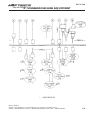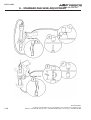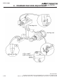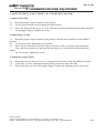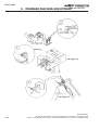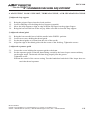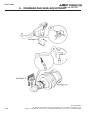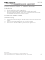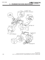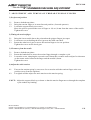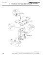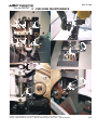
1
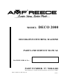
MODEL DECO 2000 DECORATIVE STITCHING MACHINE PARTS AND SERVICE MANUAL MACHINE SERIAL No.: PART NUMBER 97. 7000.0.003 This manual is valid from the machine serial No. P 704697 AMF is trademark of AMF Group, Inc. 03/2013 LIMITED WARRANTY ON NEW AMF REECE EQUIPMENT Warranty provisions: A ninety (90) day limited service labor warranty to correct defects in installation, workmanship, or material without charge for labor. This portion of the warranty applies to machines sold as ”installed” only. A one (1) year limited material warranty on major component parts to replace materials with defects. Any new part believed defective must be returned freight prepaid to AMF Reece, Inc. for inspection. If, upon inspection, the part or material is determined to be defective, AMF Reece, Inc. will replace it without charge to the customer for parts or material. Service labor warranty period shall begin on the completed installation date. Material warranty shall begin on the date the equipment is shipped from AMF Reece, Inc. Exclusions: Excluded from both service labor warranty and material warranty are: (1) Consumable parts which would be normally considered replaceable in day-to-day operations. These include parts such as needles, knives, loopers and spreaders. (2) Normal adjustment and routine maintenance. This is the sole responsibility of the customer. (3) Cleaning and lubrication of equipment. (4) Parts found to be altered, broken or damaged due to neglect or improper installation or application. (5) Damage caused by the use of non-Genuine AMF Reece parts. (6) Shipping or delivery charges. There is no service labor warranty for machines sold as ”uninstalled”. Equipment installed without the assistance of a certified technician (either an AMF Reece Employee, a Certified Contractor, or that of an Authorized Distributor) will have the limited material warranty only. Only the defective material will be covered. Any charges associated with the use of an AMF Reece Technician or that of a Distributor to replace the defective part will be the customer’s responsibility. NO OTHER WARRANTY, EXPRESS OR IMPLIED, AS TO DESCRIPTION, QUALITY, MERCHANTABILITY, and FITNESS FOR A PARTICULAR PURPOSE, OR ANY OTHER MATTER IS GIVEN BY SELLER OR SELLER’S AGENT IN CONNECTION HEREWITH. UNDER NO CIRCUMSTANCES SHALL SELLER OR SELLER’S AGENT BE LIABLE FOR LOSS OF PROFITS OR ANY OTHER DIRECT OR INDIRECT COSTS, EXPENSES, LOSSES OR DAMAGES ARISING OUT OF DEFECTS IN OR FAILURE OF THE EQUIPMENT OR ANY PART THEREOF. WHAT TO DO IF THERE IS A QUESTION REGARDING WARRANTY If a machine is purchased through an authorized AMF Reece, Inc. distributor, warranty questions should be first directed to that distributor. However, the satisfaction and goodwill of our customers are of primary concern to AMF Reece, Inc. In the event that a warranty matter is not handled to your satisfaction, please contact the appropriate AMF Reece office: Europe Prostejov, Czech Republic Phone: (+420) 582-309-286 Fax: (+420) 582-360-608 e-mail: [email protected] Warranty Registration Card (Please Fax or Mail immediately after installation) Note: All Warranty Claims Void, unless Registration Card on file at AMF Reece HQ Machine model number: (S101, S100, S104, S105, S211, Decostitch, S4000 BH,EBS Mark II, etc) Manufacturer‘s serial or production number: Installation Site Information: Customer‘s Name: Customer‘s Mailing Address: Customer‘s Telephone Number: Supervising Mechanic‘s or Technician‘s Name: Signature of Supervising Technician: AMF Reece Technician‘s Name: AMF Reece Technician‘s Signature: Type of garment produced at this location? Average Daily Production Expected from this machine? (number of buttonholes, jackets sewn, pants produced, buttons sewn, etc) Any special requirements required at this location? What other AMF Reece Machines are at this location? How can we serve you better? Tovární 837, 796 25 Prostìjov, Czech Republic Fax: +420 582 360 606, e-mail: [email protected], website: www.amfreece.com DECO 2000 TABLE OF CONTENTS PAGE A - INTRODUCTION 1. Machine DECO 2000 Basic Functions and Advantages .......................................... 1-1 2. Basic Information .................................................................................................... 1-2 3. Specification ........................................................................................................... 1-3 4. Safety Labels and Device ........................................................................................ 1-4 5. General Machine Parts Description .......................................................................... 1-5 6. Instructions for the Security of the Operator and Maintenance .................................. 1-6 7. Special Accessories ................................................................................................. 1-8 B - MACHINE INSTALLATION 1. Content of Shipping Box ......................................................................................... 1-9 2. Table Installation ..................................................................................................... 1-9 3. Accessories ............................................................................................................. 1-10 4. Connecting the Machine to the Power Supply .......................................................... 1-10 C - MACHINE CONTROLS 1. Power Up ............................................................................................................... 1-11 2. Control Panel Description ........................................................................................ 1-12 3. Sewing Speed Adjustment ....................................................................................... 1-12 4. Top Stitch and Bottom Stitch Length Adjustment ...................................................... 1-13 5. Setting the Stitch Style ............................................................................................. 1-15 6.Thread Trim - Length Adjustment ............................................................................. 1-17 7.Counter ................................................................................................................... 1-17 8. Condensed Stitch .................................................................................................... 1-19 9.Tie-Off / Back - Tack ............................................................................................... 1-20 10. Adjusting the machine - pick stitch ......................................................................... 1-22 11. Starting the Sewing ................................................................................................ 1-23 12. Error Messages ..................................................................................................... 1-24 13. Switch off the Machine .......................................................................................... 1-25 D - CORRECT MACHINE APPLICATION 1. Needle Installation ................................................................................................... 1-26 2. Threading ................................................................................................................ 1-27 Revised 03/2013 e-mail: service.cz; [email protected]; website: www.amfreece.com Phone: +420 582 309 286; fax: +420 582 360 606 DECO 2000 TABLE OF CONTENTS PAGE E - STANDARD MACHINE ADJUSTMENT 1. Adjustment .............................................................................................................. 1-28 2. Adjustment of Needle Bars ...................................................................................... 1-31 3. Adjustment and Timing of the Gripper Fingers .......................................................... 1-33 4. Adjusting loop Support, Thread Guide and Separator Guide .................................... 1-35 5. Adjustment and Timing of the Thread Lifter .............................................................. 1-37 6. Timing the Thread Brush .......................................................................................... 1-37 7. Adjusting and Timing of Thread Tension Finger ......................................................... 1-39 8. Adjustment and Timing of Material Feed .................................................................. 1-41 9. Timing the Follower Foot ......................................................................................... 1-43 10. Adjusting and Timing Left Looper and Right Looper ............................................... 1-45 11. Adjustment and Liming of Lower Looper ............................................................... 1-47 12. Adjustment and Timing of Bender Plate .................................................................. 1-49 13. Stepper Motor Adjustment .................................................................................... 1-52 14. Setting up Procedure for Feed Dog Sensor and Flag .............................................. 1-53 15. Belt Tension Adjustment ........................................................................................ 1-54 F- MACHINE MAINTENANCE 1. Principles of Machine Maintenance .......................................................................... 1-55 2. Cleaning and Maintenance the Machine ................................................................... 1-56 3. Machine Lubrication ................................................................................................ 1-56 4. Periodic Maintenance .............................................................................................. 1-58 5. Machine Disposal .................................................................................................... 1-58 Revised 03/2013 e-mail: service.cz; [email protected]; website: www.amfreece.com Phone: +420 582 309 286; fax: +420 582 360 606 DECO 2000 A - INTRODUCTION 1 . M A C H I N E D E C O 2 0 0 0 B A S I C F U N C T I O N S A N D A D VA N TA G E S 1. Decorative machine Deco 2000 was created at AMF Reece company, so that the machine maximally imitate the hand stitching and allows to select and create the stitch style. The secret of this machine is principally at the special transitivity needle system. Double pointed needle with an eye at the mid point passes through the material brings the thread from one needle bar to the other exactly as a seamstress. This machine develops the stitch with a perfect strength, higher quality and higher productivity than is the hand stitching. 2. This machine has the Microprocessor with the graphical display. Used operations in the program are easy to understand whereby symbols. It allows to the operator fast and easy setting up all needed parameters with out linguistic barriers. The adjustment of the sewing speed and stitch style are operations which can be made by one catch of screen. The other possibility of setting the parameters is to reverse of the Top stitch and Button stitch parameters by the Reverse button placed (on the right) on the plate. 3. The quality is assured on all types of fabrics by use the double pointed needle. This needle is passing through the material very lightly, does not intercept the fabric and leave far smallest hole after puncture than when the usual needle is used. The Deco 2000 machine sewing speed up to the 500 stitches per minute is ten times more productive than the hand stitching. The all stitch style parameters can be reversed at any sewing speed, which escalate the productivity and minimizes the thread waste. 4. 5. The Motor precisely positioning the needle up to the home position is another advantage of this machine. The operator can with sureness start the sewing cycle from the beginning and also automatically situate the needle up when the threading is needed. 6. Application: Edge stitching Saddle stitching Decorative stitching 7. - of jackets, overcoats, pocket flaps - jackets overcoats ladies jackets, collars and cuffs on shirts and blouses - all outwear garments, including leathewear Deco 2000 is produced in two versions Deco 2000 ATT and Deco 2000 Pick Stitch (See technical conditions page 1-3) Revised 03/2013 E-mail: [email protected]; [email protected]; website: www.amfreece.com Phones: +420 582 309 146 (Service), +420 582 309 286 (Spare Parts); Fax: +420 582 360 606 1-1 DECO 2000 A - INTRODUCTION 2 . B A S I C I N F O R M AT I O N S The sewing machine Deco 2000 is designed and produced to be very reliable. Important design goals have been to provide a safe machine that is simple and inexpensive to maintain. Special electronic and mechanical safety devices protect the operator and the machine. There is a special power lock out switch that permits the machine to be locked in the off position, so that it cannot be cycled accidentally. The drive cover is equipped with a safety switch that will not allow machine operation while the cover is open. There is an emergency off switch. There are safety - warning labels on the machine in all areas that require special care. These must not be removed. If they are lost replace them immediately. Never remove safety mechanisms or labels. Said precautions can not include all safety devices, so it is necessary for the operator before the machine is used, to read and understand to this manual. It will eliminate the mistakes during the installation, and during the operation as well. Do not start the machine if you did not read all instructions delivered with the machine and if you do not understand all functions and procedures. In this manual are incorporated three category of safety instructions : DANGER! Possible loss of life. WARNING! Possible serious injury or machine damage. NOTICE! Possible injury or machine damage. It is recommend that service workers from AMF Reece oversee the installation and initial training of your mechanics and operators. The most effective safety precaution is a well-managed safety program. Be sure those who use this machine are properly trained. Never disable safety equipment. Always wear safety goggles when operating or servicing the machine. 1-2 Revised 03/2013 E-mail: [email protected]; [email protected]; website: www.amfreece.com Phones: +420 582 309 146 (Service), +420 582 309 286 (Spare Parts); Fax: +420 582 360 606 DECO 2000 A - INTRODUCTION 3 . S P E C I F I C AT I O N S Deco 2000 ATT Machine type Description Deco 2000 Pick Stitch Electronic decorative m achine Deco 2000 or s ewing ladies and m an jackets Stitch style 150 to 500 turns per m inute/ from 75 to 250 s titches per m inute Machine Performance Sew ing Speed 500 s .p.m . Stitch Length From 0,1 to 8 m m Maxim ally 5 m m Maximum W ork Thickness Recommended Thread Lenght Cut thread from Cut thread lenght in advance from 400 — 900 m m s tandard 400 — 1200 m m (waxed) Cut thread lenght in advance from 400 — 1200 m m (waxed) Technical Specifications for condensed stitch: Range for length of s ingle s titch (Stitch Dens ity) 5 to 30 Units Maxim um length for condens ed s titch 300 Units Note: 10 units displayed on the touch panel constitute approximately 1 mm w hich may vary practically depending on the type of f abric. Automatic Thread Cutting Synthetic thread — — Silcora waxed s ilk thread (Rice) Recommended Thread Thickness Size A Lightweight m aterial Size C m edium , heavyweight m aterial Other high quality threads m ay be us ed, but m ay res ult in s om e los s of quality after threads pres s ing the garm ent and s ewing quality AMF Reece 59 - 83 - 1032 BI / Pn. 00103238 / Used Needle Size 36 Norm al weight m aterials fine thread Size 38 Norm al weight m aterials norm al thread Size 49 Heavyweight m aterials Lubrication Manually ( every day) Operating Conditions According to IEC 364 - 3, IEC 364 - 51 tem perature from +5°C to 40°C, relativeair hum idity from 30 to 80% Motor As ynchronous 3 s tage m otor 0,37 KW Electrical Requirements 1 NPE ~ 50 Hz 230 V/TN/S:1 NPE ~ 60 Hz 230 V/TN/S Table Dimension 956 (L) x 630 (W) x 850 Machine Head Dim ension 1118 m m (L) x 940 m m (W) x 1118 m m Machine Head W eight 220 kg Line Circuit Breaker Maxim ally 16 A Dimension Packed W eight 1168 m m (L) x 1041m m (W) x 1118 m m (H) 338 kg Revised 03/2013 E-mail: [email protected]; [email protected]; website: www.amfreece.com Phones: +420 582 309 146 (Service), +420 582 309 286 (Spare Parts); Fax: +420 582 360 606 1-3 DECO 2000 A - INTRODUCTION 4. S A F E T Y L A B E L S A N D D E V I C E * * * * — Deco 2000 ATT 1-4 Warning Danger - possible injury Covers removed, possible injury Standard Label Needle Bar Cover ¡ ¢ Display Table Control Box Stop Button Hand Wheel Revised 03/2013 E-mail: [email protected]; [email protected]; website: www.amfreece.com Phones: +420 582 309 146 (Service), +420 582 309 286 (Spare Parts); Fax: +420 582 360 606 DECO 2000 A - INTRODUCTION 5. G E N E R A L M A C H I N E PA R T S D E S C R I P T I O N Motor Sew Table Top Main Power Switch Start Button Foot Pedal Halogen Lamp Machine Head Reverse Button Knee Lever Thread Trim Large Tension Assembly Thread Stand Revised 03/2013 E-mail: [email protected]; [email protected]; website: www.amfreece.com Phones: +420 582 309 146 (Service), +420 582 309 286 (Spare Parts); Fax: +420 582 360 606 1-5 DECO 2000 A - INTRODUCTION 6. INSTRUCTIONS FOR THE SECURITY OF THE OPERATOR AND MAINTENANCE When the machine is set to the working area, it is recommended to keep the minimal distance said in the drawing. D A N G E R ! D o not place the machine close to the steam irons because higher temperature than is said in chapter Specifications can cause slight loss the quality of the waxed silk threads. Observe all directions said bellow. WA R N I N G ! Before machine connection to the power make sure, whether all safety covers are mounted. If it is necessary to remove some safety covers, switch off the operating switch (circuit breaker) and disconnect the machine by the fork of supply from the socket. Do not connect the machine to the power if some cover is removed. disconnection of connectors, when the machine is under electrical power is prohibited Possible damage of electrical components and motors WA R N I N G ! Remember the position of the Emergency stop button so that is possible use it from the arbitrary position. Make sure, whether supply of energy and its dimensioning and safeguarding allows permanent supply of energy needed for dependable output of the machine. Check if the electrical cables are not damaged, so that be touch with uncovered conductor, can not occur any injury. When the covers are damaged, repair or replace them immediately for the new ones. Do not touch rotary shafts by hands. In any circumstance, do not put hands to the needle space. Before changing the needle, switch off the operating switch (circuit breaker). Before cleaning or any maintenance work on the machine, disconnect the power supply by removing the plug from the socket. 1-6 Revised 03/2013 E-mail: [email protected]; [email protected]; website: www.amfreece.com Phones: +420 582 309 146 (Service), +420 582 309 286 (Spare Parts); Fax: +420 582 360 606 DECO 2000 A - INTRODUCTION - In case when the operator will not work on the machine, disconnect the power supply by removing the plug from the socket. Do not adjust the machine in any way, which could endanger its safety. Every part of the machine can be dangerous, if there is incorrect manipulation or faulty maintenance with the machine. That is why everybody, who will manipulate, maintain or operate with this machine must be acquainted with informations included in this manual. CAUTION! Perform all regular service as described by this manual. If there is any problem with power supply, turn off the mine power switch (circuit breaker). Do not remove, paint over, damage or any way change safety labels. If a safety labels are lost or cannot be easily read, order the new one in our factory and place them on the original place. Long hair and loose clothing may be dangerous near any machinery. Always contain long hair and avoid loose clothing, so that it cannot be caught by machinery and cause injury. Never use this machine while under the influence of drugs or alcohol. If anything seems to be operating incorrectly in the machine call for maintenance assistance immediately. Be sure that there is adequate light for safe operation. A normal minimum light level is 750 Lux. Do not operate the machine when changing from cold to heat. Revised 03/2013 E-mail: [email protected]; [email protected]; website: www.amfreece.com Phones: +420 582 309 146 (Service), +420 582 309 286 (Spare Parts); Fax: +420 582 360 606 1-7 DECO 2000 A - INTRODUCTION 7. SPECIAL ACCESSORIES Size 36 needle for Medium weight with Fine Thread (part number 00103236) Size 38 needle for Medium weight with Medium Thread (part number 00103238) It is possible to use different needle sizes, but it is necessary to use different neeedle bar kit for specific needle. (see table) Part Number Extra Parts Description Nedle Bar Assembly Standard 70.4253.1.078* 70.4253.1.079* 00103226 00103249 00103236 00103228 00103250 00103238 42531081* Round Needle * Two sets in machine The Recommended thread for the Deco 2000 machine is Rice WAXED THREAD. It is available in 2 sizes: Size A for Light weight materials Size C for Medium / Heavy weight materials ** “Other high quality threads may be used, with some loss of quality and production.” Needles and threads can be ordered at out distributors, where are held in stock ***To ensure consistent quality of production, use only “Genuine AMF-Reece Part & Accessories”. 1-8 Revised 03/2013 E-mail: [email protected]; [email protected]; website: www.amfreece.com Phones: +420 582 309 146 (Service), +420 582 309 286 (Spare Parts); Fax: +420 582 360 606 DECO 2000 B - MACHINE ASSEMBLY 1. CONTENT OF THE SHIPPING BOX 1. The delivery usually contains one box, if it is not mentioned otherwise during the ordering. The box contain machine and dismount table. 2. In a box is also carton with accessories and operation instruction with spare parts manual. 3. When unpacking the delivery, follow labels which are on a cover. CAUTION: If the delivery was damaged during the transport, inform the carrier. Check the contains of the delivery with order. In case that there are some faults, immediately inform the manufacturerlater complains will not be taken into consideration. 2. TABLE INSTALLATION Install the table to the hinge on the rear side of the machine. Tighten the screws well. Fold the table up and screw the holder 41441059 to the machine frame. Revised 03/2013 E-mail: [email protected]; [email protected]; website: www.amfreece.com Phones: +420 582 309 146 (Service), +420 582 309 286 (Spare Parts); Fax: +420 582 360 606 1-9 DECO 2000 B - MACHINE ASSEMBLY 3. ACCESSORIES A package of accessories is supplied with this machine, please refer to page 3-52 for detailed descriptions. 4 . C O N N E C T I O N O F T H E M A C H I N E T O T H E P O W E R S U P P LY Power supply must be 208 to 230 volts 1 phase, 50 or 60 hertz. Receptacle plug must meet requirements of IEC standard 364-4-41, its circuit breaker must be minimal 10A with characteristic C according to the EN 60947-2 (or 16A with characteristic B). No other devices must not be connected to the circuit breaker of the socker. The machine is equipped with a filters which contain capacitors which generate an high frequencyleakage current. In order to prevent nuisance tripping, residual current protection device must be protected against these high frequency currents: this is the case for industrial residual current device (example „S“ type). 1-10 Revised 03/2013 E-mail: [email protected]; [email protected]; website: www.amfreece.com Phones: +420 582 309 146 (Service), +420 582 309 286 (Spare Parts); Fax: +420 582 360 606 DECO 2000 C - MACHINE CONTROLS 1. POWER UP 1.1.Connect the machine to the power supply of appropriate voltage 230 V. To start the machine turn the main switch 1 to position 1. 1.2.The display is activated and lit up. Information about AMF REECE and the program version recorded in the machine temporarily appears on the screen. R 1.3.This screen is automatically changed to the fault screen 5. This screen informs the operator of any machine faults. Release the black STOP button 1 and press the green START button 2 and this screen will disappear. OK 1.4.The main menu appears on the screen. The machine is ready to sew or adjustments to the parameters to be made. CAUTION ! The faults will be also displayed, if the drum cover (part no. 41831082) is open. Close the drum cover and press the OK button on the screen - see chapter Troubleshooting. Revised 03/2013 E-mail: [email protected]; [email protected]; website: www.amfreece.com Phones: +420 582 309 146 (Service), +420 582 309 286 (Spare Parts); Fax: +420 582 360 606 1-11 DECO 2000 C - MACHINE CONTROLS 2. CONTROL PANEL DESCRIPTION Main menu: UP R READY SPEED - 450 500 + 150 D EDIT 1 - Set sewing speed (stitches per minute - s.p.m.). 2 - Buttons for setting the sewing speed. 3 - Press the EDIT 4 - Set stitch style. button to enter to the next menu to set the stitch length and stitch style. 5 - Press the UP button to bring the machine to the home position - (the needle is up). 6 - Mode display - Standard: - the machine is ready to sew.- backling green EDIT - the machine is in process setting parameters.- backling orange - the machine is sewing.- backling green - fault on the machine.- backling red - Errors 7 - Top stitch length parameter. 8 - Bottom stitch length parameter. 9 - Thread time 10 - Thread trim ( On / Off) 11 - Reverse is activated whwn displayed letter R. 12 - Tie off information (D - dense) 13 - Operating time counter machines 14 - Press to go to the screen Counter Count 3. SEWING SPEED ADJUSTMENT It is possible to increase or decrease the sewing speed in the range from 150 to 500 spm. The current sewing speed is shown on the upper part of the screen 1, and also by the diagram. To increase the sewing speed press the button. To decrease the sewing speed press the button. 1-12 Revised 03/2013 E-mail: [email protected]; [email protected]; website: www.amfreece.com Phones: +420 582 309 146 (Service), +420 582 309 286 (Spare Parts); Fax: +420 582 360 606 DECO 2000 C - MACHINE CONTROLS 4. TOP STITCH AND BOTTOM STITCH LENGTH ADJUSTMENT EDIT 1. To change the length of the Top stitch and Bottom stitch press the main screen. UP SPEED - button on the 450 500 150 D EDIT 2. The screen for setting the parameters appears on the display. To change the size of the Top stitch, press the top stitch value on the screen << . >> OK 3. The numerical display appears on the screen. The range of stitch length parameters is from 0 to 63. Set the required parameter for the Top stitch. Press to confirm set parameter and move back to previous screen. Use the same method to set the parameters of the Bottom stitch . Parameters selected in this numerical screen must not exceed a maximum value of 63 units, with one unit equal to 0.1 mm. to keep previous set parameter. The previous display with the original parameter Press appears on the screen. 4. When all required parameters are set, press the OK button to move to the main screen. Revised 03/2013 E-mail: [email protected]; [email protected]; website: www.amfreece.com Phones: +420 582 309 146 (Service), +420 582 309 286 (Spare Parts); Fax: +420 582 360 606 1-13 DECO 2000 C - MACHINE CONTROLS CAUTION ! If the stitch length parameter is greater than the allowed range, this note appears on the screen: Press the arrow. The previous display appears on the screen. Set the required parameter within the maximum al lowed value of 63. NOTE ! If the stitch reverse facility is required, press the blue REVERSE button on the right side of the work table. The reverse button is lit, and the letter R appears on the screen . - 500 150 D The Top stitch and Bottom stitch parameters will reverse. To return to the original parameters press the blue reverse button on the machine. The letter R will disappear. 1-14 Revised 03/2013 E-mail: [email protected]; [email protected]; website: www.amfreece.com Phones: +420 582 309 146 (Service), +420 582 309 286 (Spare Parts); Fax: +420 582 360 606 DECO 2000 C - MACHINE CONTROLS 5. SETTING THE STITCH STYLE The standard stitch is created by repeating the Top and Bottom stitch lengths during sewing. As well as the standard stitch it is possible to select another four stitch styles and set ten different lengths of Top and Bottom stitches. The operator can create the stitch style and sequence of stitches as needed. 5.1.To change the stitch style, press EDIT UP R SPEED READY 450 500 - on the main screen. 150 D EDIT 5.2. The next screen will appear on the display: << >> OK To set the stitch style, standard stitch 0 or the other stitch styles from 1 to 4, press the left or right arrow. The current set stitch style is always shown on the left corner of the display . 5.3. After the arrow is pressed the screen is changed but it is still possible to change the stitch style by the arrows and . To set the stitch length, press the >> << PROGRAM OK button . PROGRAM 5.4.The numerical screen appears on the display with first 5 columns of parameters. Touching the button 6 10 on this screen would enter into another screen for next 5 parameters and it is possible to switch back to previous screen by touching the button 1 5 . 50 40 50 15 0 20 50 0 0 0 20 30 35 50 0 25 20 0 0 0 6 10 OK 1 5 OK The first row shows the parameters of the Top stitch, the middle row shows the stitch sequence, and in the third row are parameters of the Bottom stitch length. It is possible to select ten different stitches length, which will be periodically repeated during the sewing. Top stitch + Bottom stitch = one step. To change the parameter press the number. Revised 03/2013 E-mail: [email protected]; [email protected]; website: www.amfreece.com Phones: +420 582 309 146 (Service), +420 582 309 286 (Spare Parts); Fax: +420 582 360 606 1-15 DECO 2000 C - MACHINE CONTROLS 5. The next numerical screen will appear on the display: 20 25 40 50 15 0 30 35 50 0 OK Set the required stitch length. The set stitch length is shown on the upper part of the screen . Press Enter to confirm the parameter. To keep the original set parameter press Clear. The buttons Enter and Clear always return you to the previous screen. Repeat the steps 4. and 5. until all required parameters have been set. NOTE ! If the number of selected parameters is less than ten the other parameters must be zero so that the stitch length can be periodically repeated during the sewing. For example the parameters selected in the following numerical screen looks like this when sewns: Sewing material Thread Top Stitch Steps 0 50 40 50 15 0 1 2 3 4 5 20 30 35 50 0 40 20 Krok 1 OK STYLE STITCH 1 50 30 2 15 35 50 3 0 50 4 40 20 50 30 15 35 50 0 0 Bottom Stitch 6. When all parameters are selected, press OK twice to get to the main screen. 50 40 50 15 0 >> << 20 30 35 50 6 0 10 OK OK 1 2 Then a new main menu, showing the new selected stitch style will appear on the screen. UP READY - 500 + 150 D EDIT Unless the Standard stitch style is selected, the information about the Top and Bottom stitch length will not be shown on the screen. To get this information, follow the instructions - Setting the stitch style page 1-13. 1-16 Revised 03/2013 E-mail: [email protected]; [email protected]; website: www.amfreece.com Phones: +420 582 309 146 (Service), +420 582 309 286 (Spare Parts); Fax: +420 582 360 606 DECO 2000 C - MACHINE CONTROLS 6. THREAD TRIM - LENGTH ADJUSTMENT 6.1 If you want to change the trimmed thread lenght, press UP - EDIT button. 500 150 D EDIT ° >> << OK ° button. 6.2 Press 6.3 Press + or - for increasing or reducing the value. The shows the delay / start time of the cutting 6.4 To return to the main screen, press ° equiment after retacting the thread with the looper into the machine. button. SPEED - 450 500 150 Revised 03/2013 E-mail: [email protected]; [email protected]; website: www.amfreece.com Phones: +420 582 309 146 (Service), +420 582 309 286 (Spare Parts); Fax: +420 582 360 606 1-17 DECO 2000 C - MACHINE CONTROLS 7. COUNTER 7.1 The acces the screen, press the countres . 500 150 D 7.2 On the screen there are three counters: 1 Counter top position of the needle 2 Total running time counter machines - can not delete 3 Total running time counter machines - can delete button 4 7.3 If the label on the main screen is changed to means that it is necessary to service the needle bar (see chapter E 2). UP and starts flashing, it 500 500 - - 150 150 D 1-18 Revised 03/2013 E-mail: [email protected]; [email protected]; website: www.amfreece.com Phones: +420 582 309 146 (Service), +420 582 309 286 (Spare Parts); Fax: +420 582 360 606 DECO 2000 C - MACHINE CONTROLS 8. CONDENSET STITCH - DENSE EDIT 8.1 To select the condensed stitch parameters press UP SPEED - button on the main screen. 450 500 150 D EDIT 8.2 Press button 1 . << >> OK NOTE: If the machine is lying unused and not powered continuously for more than a week to 10 days, the password may be lost and would need to be entered again to activate the “Condensed Stitch Parameter” again. 8.3 Use the buttons 1 to selected the desired number of stitches thicken. Use the buttons 2 to selected the density copression sutures. Revised 03/2013 E-mail: [email protected]; [email protected]; website: www.amfreece.com Phones: +420 582 309 146 (Service), +420 582 309 286 (Spare Parts); Fax: +420 582 360 606 1-19 DECO 2000 C - MACHINE CONTROLS 9. TIE - OFF / BACK TACK 9.1 Tie-off parameter for the selection, press the main menu screen click UP SPEED - EDIT . 450 500 150 D EDIT 9.2 Since the Back Tack Tie-off password protected, is hould be on the next screen press 1 . << >> OK 9.3 Password is supplied with a set . It is a five-digit number that you enter using the numeric keypad. NOTE: If the machine is lying unused and not powered continuously for more than a week to 10 days, the password may be lost and would need to be entered again to activate the “Condensed Stitch Parameter” again. 1-20 Revised 03/2013 E-mail: [email protected]; [email protected]; website: www.amfreece.com Phones: +420 582 309 146 (Service), +420 582 309 286 (Spare Parts); Fax: +420 582 360 606 DECO 2000 C - MACHINE CONTROLS 9.4 Press the button on the screen . << >> OK 9.5 Pressing the button repeatedlyto toggle between the two styles Tie-off Dense and Back Tack. Revised 03/2013 E-mail: [email protected]; [email protected]; website: www.amfreece.com Phones: +420 582 309 146 (Service), +420 582 309 286 (Spare Parts); Fax: +420 582 360 606 1-21 DECO 2000 C - MACHINE CONTROLS 10. ADJUSTING THE MACHINE - PICK STITCH To the customer order it is possible to adjust the machine by a mechanical mechanism called the Bender to sew a Pick Stitch which simulates a hand stitch. To change the Standard style stitch to Pick Stitch see 1-44,45. After the machine is adjusted to sew a Pick Stitch, the Pick Stitch style is shown on the screen. SPEED UP - 450 500 150 A true “Pick Stitch” can be sewn if the optional bender plate has been fitted. This options gives the advantage of placing a small stitch on each side of the fabric with a space between each stitch. This is achieved by the Bender Plate raising the fabric prior to each stitch, thereby creating a small amount of fullness in the fabric between each stitch. When sewing the pick stitch, move the angle plate locking latch lever 31000032 down. To disable the Bender from the operation, move the latch lever up. To adjust the Pick stitch length see chapter 4, to adjust the sewing speed follow the instructions in to chapter 3. If the Pick stitch is selected no other stitch style can be used. To sew another stitch style it is necessary to set the machine back to the Standard stitch. The basic difference between the Standard Stitch and Pick Stitch: Thread Sewn material 1-22 Revised 03/2013 E-mail: [email protected]; [email protected]; website: www.amfreece.com Phones: +420 582 309 146 (Service), +420 582 309 286 (Spare Parts); Fax: +420 582 360 606 DECO 2000 C - MACHINE CONTROLS 11. S TA R T I N G S E W I N G Ensure that all set parameters concur with requirements. The machine is activated by one pedal (A), but it is possible to order the machine with two pedals (B). A B A - one pedal 1. If the machine is not in the home position with the needle up, press the foot pedal in position 1 or the UP button on the left corner of the main screen to the right. The foot will raise and you 2. Move the knee lever can place the material. 0 3 1 2 to the position 2 and start sewing with 3. Press the foot pedal slow speed svitable for beginning of sewing if you press the pedal to the position 3, you will reach maximal adjusted speed. B - by two pedals 1. If the machine is not in the home position, press the right foot pedal left corner of the main screen. 2. Raise the presser foot by moving the knee lever and release the knee lift. or the UP button on the to the right. Place the material under the foot to start sewing. This pedal has two positions. By pressing the pedal to 3. Press the left foot pedal the first position the sewing speed is slow used especially at the start of sewing. To reach the maximum set sewing speed press the foot pedal fully. Revised 03/2013 E-mail: [email protected]; [email protected]; website: www.amfreece.com Phones: +420 582 309 146 (Service), +420 582 309 286 (Spare Parts); Fax: +420 582 360 606 1-23 DECO 2000 C - MACHINE CONTROLS 4. The information about the sewing speed and selected stitch style appears on the screen during the sewing. There is no possibility to change these parameters when the machine is running and run is displayed on the screen . 5 500 150 12. E R RO R M E S S A G E S If the Error message appears on the screen a fault has occurred. UP SPEED - 450 500 150 D EDIT For more informatuons see sectrion Troubleshooting - Electronic system error messages. OK 1-24 Revised 03/2013 E-mail: [email protected]; [email protected]; website: www.amfreece.com Phones: +420 582 309 146 (Service), +420 582 309 286 (Spare Parts); Fax: +420 582 360 606 DECO 2000 D - CORRECT MACHINE APPLICATION 1 . N E E D L E I N S T A L L AT I O N Use only the needles number: 00103238 made in AMF Reece as is adduced in chapter Specifications page 3. This type of needles was developed in AMF Reece. Double pointed needle which has an eye at the mid point, allows to transmitting the needle from one needle bar to the other and during the sewing maximally imitate the shape of the hand sewing. Except that, this needle does not leave so big holes in sewn material which generally improves the quality of sewing work. To replace the needle follow this steps: 1. 2. 3. 4. 5. 1-26 Bring the needle to home position by pressing the right foot pedal or by pressing the Up button on the display. To replace the needle, press the emergency Stop button. Fold the needle bar cover. Grasp the needle bar locking nuts and move the needle bar upwards. Hold the needle bar up and remove the original needle. Insert a new needle so that the groove and the eye are from the front view on the left side. Do not install a bent or broken needle. Release the needle bar and close the needle bar cover. Revised 03/2013 E-mail: [email protected]; [email protected]; website: www.amfreece.com Phones: +420 582 309 146 (Service), +420 582 309 286 (Spare Parts); Fax: +420 582 360 606 DECO 2000 D - CORRECT MACHINE APPLICATION 2. THREADING When threading see the pictures below. Easy threading allows the threading device located on the right side of the needle. 1. 2. Bring the needle to the home position by pressing the right foot pedal or by pressing the Up button on the display. Move the lever of threading device down, so that the hook passes through the needle eye. Place the thread behind a hook and release the thread device lever. Revised 03/2013 E-mail: [email protected]; [email protected]; website: www.amfreece.com Phones: +420 582 309 146 (Service), +420 582 309 286 (Spare Parts); Fax: +420 582 360 606 1-27 DECO 2000 E - STANDARD MACHINE ADJUSTMENT 1, ADJUSTMENT 1-28 Revised 03/2013 E-mail: [email protected]; [email protected]; website: www.amfreece.com Phones: +420 582 309 146 (Service), +420 582 309 286 (Spare Parts); Fax: +420 582 360 606 DECO 2000 E - STANDARD MACHINE ADJUSTMENT * — SEQUENCE IN Revised 03/2013 E-mail: [email protected]; [email protected]; website: www.amfreece.com Phones: +420 582 309 146 (Service), +420 582 309 286 (Spare Parts); Fax: +420 582 360 606 1-29 DECO 2000 E - STANDARD MACHINE ADJUSTMENT 1-30 Revised 03/2013 E-mail: [email protected]; [email protected]; website: www.amfreece.com Phones: +420 582 309 146 (Service), +420 582 309 286 (Spare Parts); Fax: +420 582 360 606 DECO 2000 E - STANDARD MACHINE ADJUSTMENT 2. A D J U S T M E N T O F N E E D L E B A R S 1.) Adjust the upper needle bar 1.1. 1.2. 1.3. 1.4. Move the upper needle bar to its DWELL position. Use the square head adjustment on the rear of the rocker arm to move the needle bar up and down. First loosen the clamping screw. Use the gauge from the accessories 37771023 to measure 14,2 mm between the lip on the needle bar - not the sleeve to the throat plate. Adjust the upper needle bar to the gauge. Tighten the clamping screw. 2) Adjust the lower needle bar 2.1. 2.2. 2.3. 2.4. 2.5 Bring the needle bar to the closest point while transferring the needle. Use the square head adjustment on the rear of the lower rocker arm to move the needle bar up and down. First loosen the clamping screw. Use the gauge 37771-023 to measure 23,8 mm between the lip on the lower needle bar and the lip on the upper needle bar. Do not measure to the needle sleeves. Adjust the lower needle bar to the gauge. Tighten the clamping screw. Move the needle up and down. The needle should be free to move 0,4 to 1,2 mm. 3) Adjust the needle release 3.1. 3.2. 3.3. 3.4. With the needle in the upper needle bar, rotate the handwheel to bring the needle just to the transfer point to the lower needle bar. Move the handwheel back and forth slightly to test the needle release from the upper needle bar. Loosen the jam nut on the top of the needle bar . Rotate the sleeve adjust nut counterclockwise (viewed from above) quarter turn at a time until the needle does not release. Reverse the nut clockwise until the needle just release at the transfer point. Turn clockwise (half turn). Tighten the jam nut. Make the same adjustment on the lower needle bar to get needle release from the lower needle bar to the upper needle bar. Oscillate the handwheel to assure that the needle transfers properly. Revised 03/2013 E-mail: [email protected]; [email protected]; website: www.amfreece.com Phones: +420 582 309 146 (Service), +420 582 309 286 (Spare Parts); Fax: +420 582 360 606 1-31 DECO 2000 E - STANDARD MACHINE ADJUSTMENT 1-32 Revised 03/2013 E-mail: [email protected]; [email protected]; website: www.amfreece.com Phones: +420 582 309 146 (Service), +420 582 309 286 (Spare Parts); Fax: +420 582 360 606 DECO 2000 E - STANDARD MACHINE ADJUSTMENT 3. A D J U S T M E N T A N D T I M I N G O F G R I P P E R F I N G E R S 1) Align to the needle 1.1. 1.2. 1.3. Bring the gripper fingers into the closed position. Loosen two mounting screws holding the finger bracket Move the finger bracket to get 0,13 mm clearance between the needle and the end of the pads on the gripper fingers. Tighten the screws. 2) Adjust finger closing 2.1. Bring the gripper fingers into the closed position with the lower needle bar in the DWELL position. 2.2. Loosen two screws holding the pivot bracket. 2.3. Move the pivot bracket to close the fingers. Be sure to remove all play in the mechanism. There must be clearance 0,4 mm between the finger lever and the pivot bracket when the fingers are closed only! Tighten the screws. 3) Timing the gripper fingers 3.1. 3.2. 3.3. Bring the lower needle bar at 0,8 a• 0,4 mm before the needle reaches the DWELL position. Loosen the 3 screws clamping the thread clamp cam on the main cam shaft. Rotate the cam to just close the gripper fingers. Tighten the clamping screws on the cam. Revised 03/2013 E-mail: [email protected]; [email protected]; website: www.amfreece.com Phones: +420 582 309 146 (Service), +420 582 309 286 (Spare Parts); Fax: +420 582 360 606 1-33 DECO 2000 E - STANDARD MACHINE ADJUSTMENT 1-34 Revised 03/2013 E-mail: [email protected]; [email protected]; website: www.amfreece.com Phones: +420 582 309 146 (Service), +420 582 309 286 (Spare Parts); Fax: +420 582 360 606 DECO 2000 E - STANDARD MACHINE ADJUSTMENT 4. A D J U S T I N G L O O P S U P P O R T, T H R E A D G U I D E , A N D S E PA R AT O R G U I D E 1) Adjust the loop support 1.1. 1.2. 1.3. 1.4. Bring the gripper fingers into the closed position. Loosen clamping screw holding the loop support (pyramid). Move the loop support to align its edge with the top fingers on the gripper fingers. Bring the lower needle bar all the way up. Make sure that it clears the loop support. 2) Adjust the thread guide 2.1. 2.2. 2.3. 2.4. Bring the lower needle bar to hold the needle in the DWELL position. Loosen two screws holding the thread guide. Set the thread guide at 0,8 mm from the side of the needle. Align the edge of the thread guide with the center of the feed dog. Tighten the screws. 3) Adjust the separator guide 3.1. 3.2. Loosen the screw holding the separator guide to the drum. Set the separator guide so that the thread being carried by the lower looper contacts midway on the upper angle. The thread will then drop properly into the groove. Tighten the screw. Perform the control of the correct setting. Turn the handwheel and check if the looper does not touch the thread separator. Revised 03/2013 E-mail: [email protected]; [email protected]; website: www.amfreece.com Phones: +420 582 309 146 (Service), +420 582 309 286 (Spare Parts); Fax: +420 582 360 606 1-35 DECO 2000 E - STANDARD MACHINE ADJUSTMENT 1-36 Revised 03/2013 E-mail: [email protected]; [email protected]; website: www.amfreece.com Phones: +420 582 309 146 (Service), +420 582 309 286 (Spare Parts); Fax: +420 582 360 606 DECO 2000 E - STANDARD MACHINE ADJUSTMENT 5. A D J U S T M E N T A N D T I M I N G O F T H E T H R E A D L I F T E R 1) Adjust lifter hook 1.1. 1.2. Move the thread lifter to complete its upward travel. Adjust the lifter hook to lift the thread fully into the slot of the separator guide. Do not pinch the thread. Tighten the screw. Check if the lifter hook is not touch by looper after adjustment. The lifter hook can not touch the looper! 6. T I M I N G T H E T H R E A D B R U S H 1) Thread brush opening 1.1. 1.2. 1.3 Bring the lower needle bar to the point where the needle just starts to move from the dwell position. Loosen two screws of the brush operating cam on the main cam shaft. Rotate the cam to where the thread brush just starts to open. Tighten the cam Revised 03/2013 E-mail: [email protected]; [email protected]; website: www.amfreece.com Phones: +420 582 309 146 (Service), +420 582 309 286 (Spare Parts); Fax: +420 582 360 606 1-37 DECO 2000 E - STANDARD MACHINE ADJUSTMENT 1-38 Revised 03/2013 E-mail: [email protected]; [email protected]; website: www.amfreece.com Phones: +420 582 309 146 (Service), +420 582 309 286 (Spare Parts); Fax: +420 582 360 606 DECO 2000 E - STANDARD MACHINE ADJUSTMENT 7. A D J U S T M E N T A N D T I M I N G O F T H R E A D T E N S I O N F I N G E R 1) Set forward position 1.1. 1.2. 1.3. Remove both throat plates. Bring the tension finger to its most forward position (forward operator). Loosen the support block pivot screw. Move the pivot to position the nose of finger at 4,8 to 6,4 mm from the center of the needle. Tighten the screw. 2) Timing the tension finger 2.1. 2.2. 2.3. Bring the lower needle bar to the point when the gripper fingers just open. Loosen two screws holding the bevel gear on the main cam shaft. Rotate the other bevel gear to move the tension finger to its rear position. Tighten the screws on the bevel gear. 3) Clearance from the needle 3.1. 3.2. 3.3. Remove both throat plates. Rotate the handwheel to move the tension finger through a complete cycle. Loosen the screw clamping the eccentric stud. Rotate the eccentric stud to adjust for clearance on the return stroke between the finger and the needle 0,8 mm. Tighten the screw. 4) Adjust the stitch tension 4.1. 4.2. First set the tension spring by one screw for no tension with the tension finger at the rear position (away from the operator). For tighter stitches adjust for more tension on the tension spring N O T E : Adjust the support block up or down so that the tension finger moves through the complete cycle without any binding. Revised 03/2013 E-mail: [email protected]; [email protected]; website: www.amfreece.com Phones: +420 582 309 146 (Service), +420 582 309 286 (Spare Parts); Fax: +420 582 360 606 1-39 DECO 2000 E - STANDARD MACHINE ADJUSTMENT 1-40 Revised 03/2013 E-mail: [email protected]; [email protected]; website: www.amfreece.com Phones: +420 582 309 146 (Service), +420 582 309 286 (Spare Parts); Fax: +420 582 360 606 DECO 2000 E - STANDARD MACHINE ADJUSTMENT 8. A D J U S T M E N T A N D T I M I N G O F M AT E R I A L F E E D 1) Position the timing of material feed 1.1. 1.2. 1.3. Bring the eye of the needle flush with the throat plate. Loosen the throat plate holder, by two screws, holding the throat plates. Position the throat plate for 0,08 a• 0,13 mm clearance of the forward end of the slot from needle eye. Make sure that the feed dog and the bender plate are free to operate. Tighten the throat plate holder making sure that it is square with the back casting. 2) Adjust feed dog angle 2.1. 2.2. 2.3. 2.4. Perform this adjustment and the adjustment feed dog height at the same time. Bring the feed dog above the throat plate. Loosen two screws on the material feed arm to adjust the feed dog. Adjust the upper surface of the feed dog parallel with the throat plate. Tighten the screws. 3) Adjust feed dog height 3.1. 3.2. 3.3. Bring the feed dog above the throat plate . Use the lifter rod to raise or lower the feed dog. Loosen the upper jam nut. Loosen the lower jam nut ( left hand thread ). Adjust the feed dog for 0,4 a• 0,8 mm. above the throat plate. Tighten the jam nuts. 4) Adjust feed dog timing 4.1. 4.2. Bring the needle bar at 0,4 a• 0,8 mm. before the needle reaches the dwell position. Loosen the material feed cam and rotate to just bring the feed dog all the way up. Tighten the feed cam. Revised 03/2013 E-mail: [email protected]; [email protected]; website: www.amfreece.com Phones: +420 582 309 146 (Service), +420 582 309 286 (Spare Parts); Fax: +420 582 360 606 1-41 DECO 2000 E - STANDARD MACHINE ADJUSTMENT 1-42 Revised 03/2013 E-mail: [email protected]; [email protected]; website: www.amfreece.com Phones: +420 582 309 146 (Service), +420 582 309 286 (Spare Parts); Fax: +420 582 360 606 DECO 2000 E - STANDARD MACHINE ADJUSTMENT 9. T I M I N G T H E F O L L O W E R F O O T 1) Adjust the follower foot separation 1.1. This adjustment requires a long arm key or an extension to a standard key. Bend the key as required for access to the gear screw. 1.2. Remove the belt guard. Unhook the cam lever spring for the upper looper. 1.3. Rotate the handwheel to bring the set on the presser foot gear into view. Loosen the set screw. 1.4. Rotate the handwheel to bring the feed dog to the end of stroke where it starts to descend. The follower foot should move upward at this time. Determine whether to advance the follower foot to move upward sooner or retard the follower foot to move later. 1.5. Rotate the handwheel to where the low section of the left upper looper cam uncovers the presser foot gear. 1.6. Hold the right cam looper gear in place. Pull the presser foot gear to disengage from the gearing. Rotate the presser foot gear clockwise to retard the follower foot or counterclockwise to advance. Push the gear in to engage the gearing. Rotate the handwheel to check the timing of the follower foot to the feed dog. 1.7. Repeat steps 5 and 6 until the follower foot separates from the feed dog at the end of its stroke. Rotate to bring the set screw on the presser foot gear into view and tighten the screw. Replace the upper looper cam lever spring. Replace the belt guard. Check the right looper timing. 1.8. Revised 03/2013 E-mail: [email protected]; [email protected]; website: www.amfreece.com Phones: +420 582 309 146 (Service), +420 582 309 286 (Spare Parts); Fax: +420 582 360 606 1-43 DECO 2000 E - STANDARD MACHINE ADJUSTMENT 1-44 Revised 03/2013 E-mail: [email protected]; [email protected]; website: www.amfreece.com Phones: +420 582 309 146 (Service), +420 582 309 286 (Spare Parts); Fax: +420 582 360 606 DECO 2000 E - STANDARD MACHINE ADJUSTMENT 10. A D J U S T M E N T A N D T I M I N G , L E F T L O O P E R A N D R I G H T L O O P E R 1) Left looper dwell position 1.1. Loosen two screws to remove the belt guard at the handwheel and of the machine for access to the cam lever. 1.2. Bring the upper needle bar to its maximum upward position. 1.3. Loosen the cam lever screw and locate the tip of the left looper at 4,8 mm from the needle. 2) Left looper clearance 2.1. 2.2. Rotate the handwheel to bring the left looper alongside the needle. Check for 0,2 a• 0,8 mm clearance between the left looper and the needle. If necessary, carefully bend the looper arm to get the proper clearance. 3) Left looper height 3.1. 3.2. Loosen the left looper arm and adjust the arm to just clear the needle bar on the return stroke. Tighten the arm. Run the left looper thought its motion a few times to assure that the arm does strike the needle bar on the return stroke. 4) Right looper dwell 4.1. 4.2. Bring the upper needle bar to its maximum upward position. Loosen the right looper cam lever. Move the right looper for 1,6 a• 0,8 mm clearance from the upper needle bar. Tighten the cam lever 5) Looper timing 5.1. 5.2. Bring the upper needle bar just to its dwell position. Loosen the right looper cam. Rotate the cam to advance the right looper to 0,8 mm ahead of the left looper. Tighten the cam. N O T E : The right looper picks up the thread ahead of the left looper. Revised 03/2013 E-mail: [email protected]; [email protected]; website: www.amfreece.com Phones: +420 582 309 146 (Service), +420 582 309 286 (Spare Parts); Fax: +420 582 360 606 1-45 DECO 2000 E - STANDARD MACHINE ADJUSTMENT 1-46 Revised 03/2013 E-mail: [email protected]; [email protected]; website: www.amfreece.com Phones: +420 582 309 146 (Service), +420 582 309 286 (Spare Parts); Fax: +420 582 360 606 DECO 2000 E - STANDARD MACHINE ADJUSTMENT 1 1. A D J U S T M E N T A N D T I M I N G O F L O W E R L O O P E R 1) Timing the drive gibs 1.1. Rotate the handwheel by hand to transfer the needle to the upper needle bar. Stop at the point that the retainer ring on the upper needle bar (moving upward) is just flush with the bottom of the needle bar bushing. 1.2. Loosen the arm crank screw. Hold the arm crank assembly and move the lower looper arm out far enough to remove the arm crank. 1.3. Bellow the handwheel remove the nut holding the arm crank drive gear. 1.4. Mark the position of the material feed drive gear. 1.5. Pull the arm crank drive to gear to disengage from the gearing and rotate to make the drive gibs point vertically downward. Reengage the arm crank drive gear to the gearing. Check that the material feed drive gear has not moved. 1.6. Replace the nut on the gear stud and tighten. 1.7. Install the arm crank assembly on the shaft of the lower arm and make sure that the looper arm is seated. Do not tighten. Proceed to the instructions for Timing the lever looper. C A U T I O N ! Whenever the arm crank drive gear is disengaged, all other timings and adjustments must be checked 2) Timing the lower looper 2.1. Bring the lower needle bar to 0,4 mm before the needle reaches its dwell position. The gripper fingers should just close. 2.2. Loosen the arm crank screw. Hold the drive gibs in place and rotate the bottom looper to position its tip at (12,7 mm Deco 2000 Pick Stitch ) (1 mm Deo 2000 Standard) from the slot in the gripper fingers. Tighten the screw. 3) Align the lower hook tip 3.1. Bring the tip of the lower hook to the gripper fingers. 3.2. Align the tip of the hook at 2 — 3 mm below the top edge of the gripper fingers (screw at the end of looper arm). Tighten the screw. Revised 03/2013 E-mail: [email protected]; [email protected]; website: www.amfreece.com Phones: +420 582 309 146 (Service), +420 582 309 286 (Spare Parts); Fax: +420 582 360 606 1-47 DECO 2000 E - STANDARD MACHINE ADJUSTMENT 1-48 Revised 03/2013 E-mail: [email protected]; [email protected]; website: www.amfreece.com Phones: +420 582 309 146 (Service), +420 582 309 286 (Spare Parts); Fax: +420 582 360 606 DECO 2000 E - STANDARD MACHINE ADJUSTMENT 1 2. A D J U S T M E N T A N D T I M I N G O F B E N D E R P L AT E 1) Raised position of bender plate 1.1. 1.2. 1.3. 1.4. Loosen two screws to remove the metal table - holder of the throat plates. Release the angle plate latch for pick stitch operation. Rotate the handwheel to bring the benderplate fully up. Loosen the screw attaching the pusher plate. Lift the presser foot away from the bender plate. Move the bender plate for 0,4 mm clearance from the needle. Tighten the screw. 2) Adjust bender plate height 2.1. 2.2. Bring the bender plate into the down position. Loosen the jam nut on the bracket rod. Turn the adjusting bushing to align the end of the benderplate towards the operator flush with the throat plate. This should set the opposite end of the bender plate at 0,4 mm above the throat plate. Tighten the jam nut. 3) Align to the throat plate 3.1. 3.2. 3.3. Loosen the clamping screw and also loosen two screws holding the pivot support. Align the edge of the notch for the feed dog on the bender plate with the edge of the feed dog slot on the throat plate. Tighten the pivot support screws. Adjust the pins to the bender plate and tighten the clamping screw. 4) Timing the plate 4.1. 4.2. 4.3. 4.4. 4.5. Release the angle plate latch for pick stitch operation. Rotate the handwheel to move the needle into the lower needle bar. Rotate to bring the presser foot down to the throat plate. Stop when the presser foot is 0,4 mm above the throat plate. Loosen two screws holding the angle plate cam on the main cam shaft. Rotate the cam to just start the bender upward. Tighten the cam. Revised 03/2013 E-mail: [email protected]; [email protected]; website: www.amfreece.com Phones: +420 582 309 146 (Service), +420 582 309 286 (Spare Parts); Fax: +420 582 360 606 1-49 DECO 2000 E - STANDARD MACHINE ADJUSTMENT 1-50 Revised 03/2013 E-mail: [email protected]; [email protected]; website: www.amfreece.com Phones: +420 582 309 146 (Service), +420 582 309 286 (Spare Parts); Fax: +420 582 360 606 DECO 2000 E - STANDARD MACHINE ADJUSTMENT 5) Adjust the angle plate latch 5.1. 5.2. 5.3. Rotate the handwheel to bring the roller onto the high section of the angle plate cam on the main cam shaft. Loosen the mounting of the angle plate latch two screws on the tie bracket. Adjust the latch to snap onto locking clip. Tighten the mounting. 6) Adjust cam lever spring 6.1. 6.2. 6.3. Loosen the jam nut on the stud attaching the cam lever spring to tie bracket. Use the other nut to adjust the pressure of the roller on the cam lever against the angle plate cam. Operate the machine. The roller should stay in positive contact with the cam. Tighten the jam nut. 7) Presser foot tension 7.1. Run the upper nut on the top of the presser foot rod to two threads from the top. 7.2. Turn the underneath nut to move the spring clip against the upper nut. Tighten the two nuts. 8) Rod spring compression 8.1. 8.2. 8.3. 8.4 8.5. Bring the bender plate to the fully up position. Lift the presser foot and then reset on the bender plate. The presser foot should move down to contact the throat plate. Loosen the collar under the rod spring on the angle stitch mechanism. Rotate the collar to increase or decrease the compression of the rod spring. Find the point that the bender plate just lifts the presser foot away from the throat plate. Then back off two turns on the collar to decrease the compression on the rod spring. Tighten the collar. Operate the machine to check the stitching on the material being used. If the stitch length varies increase the compression on the rod spring. Revised 03/2013 E-mail: [email protected]; [email protected]; website: www.amfreece.com Phones: +420 582 309 146 (Service), +420 582 309 286 (Spare Parts); Fax: +420 582 360 606 1-51 DECO 2000 E - STANDARD MACHINE ADJUSTMENT 1 3. S T E P M O T O R S E T U P Set up the gap 0,25 mm between the sensor face and flag on the cam. 1-52 Revised 03/2013 E-mail: [email protected]; [email protected]; website: www.amfreece.com Phones: +420 582 309 146 (Service), +420 582 309 286 (Spare Parts); Fax: +420 582 360 606 DECO 2000 E - STANDARD MACHINE ADJUSTMENT 1 4. S E T T I N G - U P P R O C E D U R E F O R F E E D D O G S E N S O R A N D F L A G Ensure 0,8 mm gap between feed dog sensor and assembly. Sensor cable harness connector must be fitted into SK 3 on main card. Check correct mains voltage setting is selected. Switch on machine. Pull the handwheel round by hand keeping an eye on feed dog as feed dog goes below throat plate stop. Adjust flag assembly next to feed dog sensor so small red L.E.D. just comes on. Tighten flag and sensor maintaining 8 mm gap. Revised 03/2013 E-mail: [email protected]; [email protected]; website: www.amfreece.com Phones: +420 582 309 146 (Service), +420 582 309 286 (Spare Parts); Fax: +420 582 360 606 1-53 DECO 2000 E - STANDARD MACHINE ADJUSTMENT 1 5. B E LT T E N S I O N A D J U S T M E N T S The V belt can be released after some time of using the machine, which may worsen the productivity. That is why its necessary to check the belt tension. 1. 2. 3. 4. 5. 1-54 To tighten the V belt fold the machine working table and loosen two nuts 06000014 and two screws 0400004. Move the bracket down as needed and tighten two nuts. After the V belt is adjusted it is necessary to adjust the T belt: Loosen the nuts, move the motor downas needed and then tighten the screws. Check the tension by the pressure approximately 10 N above the plate. The sag of the belt should be approximately 10 mm. To tighten the belt on the step motor 24381054 loosen the screw on the step motor holder 31000006 and move the holder with step motor in direction away from the machine. Tighten the screw. Revised 03/2013 E-mail: [email protected]; [email protected]; website: www.amfreece.com Phones: +420 582 309 146 (Service), +420 582 309 286 (Spare Parts); Fax: +420 582 360 606 DECO 2000 F - MACHINE MAINTENANCE 1. PRINCIPLES OF MACHINE MAINTENANCE WA R N I N G : - To make any maintenance turn off the main switch. - Do not modify the machine in any way, which could damage electronic devices and machine mechanisms. CAUTION: - Always keep the safety rules valid in the organization. WA R N I N G : -Check if the electrical cables are not damaged. -Check safety covers for damage and replace if needed immediately. -Keep your hands out of the sewing area! -Do not modify the machine in any way which could eliminate safety parts. CAUTION: -Do not neglect periodic maintenance. -If there is problem with electrical power supply, switch off the operating switch (circuit breaker) -Do not damage, correct and remove safety labels. -Do not work with the machine when you are under the influence of drugs or alcohol. -User has to ensure the lighting of the working area minimal 750 Luxes. Revised 03/2013 E-mail: [email protected]; [email protected]; website: www.amfreece.com Phones: +420 582 309 146 (Service), +420 582 309 286 (Spare Parts); Fax: +420 582 360 606 1-55 DECO 2000 F - MACHINE MAINTENANCE 2. M A C H I N E C L E A N I N G A N D M A I N T E N A N C E 1. Switch off the electrical power supply. 2. Use the brushes from the accessories to clean the thread lints and fabric from the sewing mecha nism. Turn the handwheel to rotate with the sewing mechanism. Clean the thread waste from the roller daily. Lift the working table and perform the cleaning by the air-blowing. Do not forget to clean the waste on the control box air gird. WA R N I N G ! When covering the working table take care of hands. Possible injury! 3. Lubricate the machine daily 4. Perform visual check of mechanism especially in area of sewing mechanism. 5. When the maintenance and checking is finished, close covers. 3. M A C H I N E L U B R I C A T I O N 1. It is necessary to lubricate daily all places said below, lubricate soundly especially when the machine is switched on for the first time or after a long idle period. Use the oil ESSO TERESSO 68 or oil with similar quality. 2. Too much oil may cause its overflowing around the needle bar area. 3. To lubricate the needle bar fold the needle bar cover. Few drops of oil drop on the needle bar above bearing , to the needle bar center, and do not forget to lubricate the lower needle bar and conducting sleeve area. Close the cover. 1-56 Revised 03/2013 E-mail: [email protected]; [email protected]; website: www.amfreece.com Phones: +420 582 309 146 (Service), +420 582 309 286 (Spare Parts); Fax: +420 582 360 606 DECO 2000 F - MACHINE MAINTENANCE Revised 03/2013 E-mail: [email protected]; [email protected]; website: www.amfreece.com Phones: +420 582 309 146 (Service), +420 582 309 286 (Spare Parts); Fax: +420 582 360 606 1-57 DECO 2000 F - MACHINE MAINTENANCE 4. P E R I O D I C M A I N T E N A N C E (10 hours of operation) (80 hours of operation) (300 hours of operation) -cleaning of the sewing mechanism area -cleaning the inner frame of the machine -lubrication of the needle bars and sewing mechanisms -visual check - external and internal mechanism -check the screw connections tightening -check the waste on the control box air grid. -check the belts tension 5. MACHINE DISPOSAL 1. To ensure ecological disposal it is necessary to remove especially nonmetallic parts from the ma chine. To take these parts out, it is necessary to perform the partial dismantling of the machine, remove covers, dismantle the machine arm and remove the frame. 2. Aluminium and duralumin parts must be treated separately, also nonferrous metal parts and plastic parts 3. Parts mentioned in point 2 can be found in the spare parts manual with these marks: z aluminium parts zz non - ferrous metal parts zzz plastic and non - metallic parts 1-58 Revised 03/2013 E-mail: [email protected]; [email protected]; website: www.amfreece.com Phones: +420 582 309 146 (Service), +420 582 309 286 (Spare Parts); Fax: +420 582 360 606 DECO 2000 TROUBLESHOOTING TABLE OF CONTENTS Page Introduction .......................................................................................................... 2-2 Adjustments quick reference list ............................................................................ 2-2 FAULTS WITHOUT ERROR MESSAGES Thread breakage................................................................................................... 2-3 The machine does not sew .................................................................................... 2-3 Skip stitches ......................................................................................................... 2-3 The electronic system error messages .................................................................... 2-4 Fuse description .................................................................................................... 2-5 THE ELECTRONIC SYSTEM FAULTS After the machine is switched on the display is not light........................................... 2-6 After the machine is switched on the work light is not operate ................................. 2-6 After the start button is pressed the machine does not start operating ...................... 2-6 Sewing motor is not turning ................................................................................... 2-6 Step motor is not moving....................................................................................... 2-6 Released 03/2013 e-mail: [email protected]; [email protected]; website: www.amfreece.com Phone: +420 582 309 286; Fax: + 420 582 360 606 2-1 DECO 2000 TROUBLESHOOTING 1. INTRODUCTION Warning! Inspect the machine on a regular basis and use only quality parts. The manufacturer recommends using original AMF Reece parts, especially needles, loopers, and throat plates. The Deco 2000 electronically displays error massages, when worn or damaged parts are detected. If machine problems occur and the error is not displayed, ensure correct needle installation and threading. The other troubles are eliminated according to the detailed descriptions listed. 2. ADJUSTMENTS QUICK REFERENCE LIST N O T E : Required machine settings are variable according to the fabric and thread variation used. The type of thread and fabric will affect the amount of wear on the machine parts. To obtain the highest quality of the sewing work maintain the following values: The distance between the upper needle bar and the threat plate 14.3 mm. The clearance between the lip of lower needle bar and lip on the upper needle bar 23,8 mm. Needle clearance 0,4 to 1,2 mm. The clearance between the needle and the end of the pads on the gripper fingers 0,13 mm. The clearance between the fingers lever and pivot bracket must be 0,4 mm but when the fingers are closed only. Keep the clearance between the thread guide and the side of the needle 0,8 mm. The loopers can not catch the thread separator. The lifter hook can not catch the looper. The clearance of the forward end of the slot from the needle eye 0,08 to 0,13 mm. The clearance between the feed dog above the throat plate 0,4 - 0,8 mm. The clearance of the needle bar to the dwell position 0,8 to 0,4 mm. The clearance of the left looper tip from the center of the needle 4,8 mm. Clearance between the left looper and the needle 0,4 to 0,8 mm. Clearance from the right looper to the upper needle bar 1,6 to 0,8 mm. The clearance of right looper to the 0,8 ahead of the left looper. The clearance between the lower looper tip and before the needle 12,7 mm. The tip of the hook 0,8 below the top of the edge of the gripper fingers. The bender plate clearance to the needle 0,4 mm. Gap between the sensor face and flag on cam 0,254 mm. The gap between feed dog sensor and flag assembly 8 mm. 2-2 Revised 03/2013 e-mail: [email protected]; [email protected]; website: www.amfreece.com Phone: +420 582 309 286; Fax: + 420 582 360 606 DECO 2000 TROUBLESHOOTING 3. F A U LT S W I T H O U T E R R O R M E S S A G E S SYMPTOM Thread breakage. POSSIBLE CAUSE Thread draw - off is too tight. PROBABLE SOLUTION Reduce thread tension Damaged loopers or throad plate. Replace damaged parts. Incorrect needle and sewing mechanism adjustment. Poor thread quality. Thread holes in the needle and looper are too small. The needle transfer does not work, needle breakage. Use correct parts. Damaged the thread separator, worn right looper. Replace damaged parts. The roller is not rotating. Clean the roller. The machine does not sew. Bent or broken needle. Skip stitches. Correctly adjust the timing of sewing mechanism. Use high quality threads only. Roll the needle on a smooth flat surface, if bent, replace the needle. Damaged throad plate. Deburr or replace the looper. Incorrect sewing system adjustment. Correctly adjust. Incorrect thread draw-off. Correctly adjust thread spring and timing of the thread tension finger. Bent needle or damaged stitch forming parts. Replace the damaged parts. Incorrectly adjusted sewing mechanism. Correctly adjust the sewing mechanism. Spring plunge or the springs in the needle bars are worn. Released 03/2013 e-mail: [email protected]; [email protected]; website: www.amfreece.com Phone: +420 582 309 286; Fax: + 420 582 360 606 Replace damaged parts. 2-3 DECO 2000 TROUBLESHOOTING 4. T H E E L E C T R O N I C S Y S T E M E R R O R M E S S A G E S If the Error message ➊ appears on the screen a fault has occurred. Press button ➊. SPEED UP 450 500 150 D EDIT Next a list of errors appears on the screen. This message informs the operator what is wrong. Repair the machine. Press button ➋. For more informations see table bellow. OK List of the error messages, possible cause, probable solution: Error messages Cause Solution Close the drum cover and tighten the locking screw. Press the button OK. COVER The drum cover is open (Part number: 41831082) FREQ. INVENTER The machine is stopped by STOP button Press the START button. Broken stepper motor driver. Turn off the machine at last 1 minute. If the display is switched on again after an error, check the stepper motor driver and power supply. Set parameter is incorrect Press the arrow on the display and select the parameters in correct range STEPPERMOTOR SET NUMBER IS INCORRECT 2-4 Revised 03/2013 e-mail: [email protected]; [email protected]; website: www.amfreece.com Phone: +420 582 309 286; Fax: + 420 582 360 606 DECO 2000 TROUBLESHOOTING 5 . E L E CTRONIC SYSTEM FAULTS - fuse description FUSE TYPE INSURED PART FAULT Work light The light does not operate The source GS 1 primary part. The LED on GS 1 is not light. The LED on PLC is not light. The display is not light. F 2 - T10A 12.0008.4.664 Frequency inventer U 1. Frequency inventer faults. F 3 - T1,6A 12.0008.4.064 The source GS 2 primary part. The source GS 2 secondary part. Step motor faults. F 1 - T2A, 12.0008.4.665 . F 4 - T 10A 120008.4.664. Released 03/2013 e-mail: [email protected]; [email protected]; website: www.amfreece.com Phone: +420 582 309 286; Fax: + 420 582 360 606 Step motor faults. 2-5 DECO 2000 TROUBLESHOOTING 6. T H E E L E C T R O N I C FA U LT S SYMPTOM After the machine is switched on, the display is not light. POSSIBLE CAUSE No power supply. Power switch QS 1 is damaged. PROBABLE SOLUTION Check main power supply or voltage in the socket. Replace the switch 12.0008.4.835. Fuse F 1 failure (the LED on the power supply GS1 does not light). Replace the fuse 12.0008.4.665. Faulty display. Replace the display 70.8001.1.004. After the Start button is pressed the machine does not start operating. Contactor KM 1 does not switch on. Check the contactor KM circuits, it means button SB2 Start, SB1 Stop, Control press pushbutton start (SB2) or stop (SB1) Cover BQ6, or replace the contactor 12.0008.4.488. Sewing motor is not turning. Fuse F2 failure. Replace the fuse 12.0008.4.664. Faulty driver motor. Check the or replace the driver motor U1 - 70.8001.1.002 Faulty sewing motor. Replace motor M 1 - 12.0008.4.757. Step motor is not moving. Cutting threads is not work. 2-6 Fuse F3 or F4 failure. Power led driver U2 no light. Replace fuse F3 - 12.0008.4.064 or F4 - 12.0008.4.664. Sensor BQ2 failure. Test sensor BQ2, replace sensor 12.00104.025 Faulty driver U2. Replace driver 12.0010.4.161. Faulty step motor. Replace motor 06.7000.0.004 Faulty relay KA 1 Replace relay 12.0008.4.720 Faulty cutting solenoid Replace solenoid 70.4165.1.129 Revised 03/2013 e-mail: [email protected]; [email protected]; website: www.amfreece.com Phone: +420 582 309 286; Fax: + 420 582 360 606