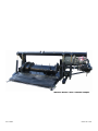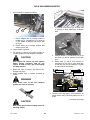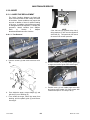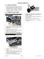
1
CA20
Combine Adapter
OPERATOR’S MANUAL
Model Year - 2009
Part #169009 $15
MacDon Model CA20 Combine Adapter
Form 169009
Model Year - 2009
1 INTRODUCTION
This manual contains information on the MacDon Model CA20 Combine Adapter that allows attachment of the
MacDon Model D50 and D60 Harvest Header and the Model FD70 FlexDraper headers to various makes and
models of combines. This manual must be used in conjunction with your Header and Combine Operator's
Manual.
CAREFULLY READ ALL THE MATERIAL PROVIDED BEFORE ATTEMPTING TO UNLOAD, ASSEMBLE, OR
USE THE MACHINE.
Use this manual as your first source of information about the machine. If you follow the instructions given in this
manual, your CA20 Combine Adapter will work well for many years. If you require more detailed service
information, a Service Manual is available from your dealer.
Use the Table of Contents and the Index to guide you to specific areas. Study the Table of Contents to
familiarize yourself with how the material is organized.
Keep this manual handy for frequent reference and to pass on to new operators or owners. Call your dealer if
you need assistance, information, or additional copies of this manual.
NOTE: Right-hand (R/H) and left-hand (L/H) designations are determined from the operator’s position, facing
forward.
RECORD THE SERIAL NUMBER IN THE SPACE BELOW.
____________________________________
Serial Number plate is located on the frame
above the main drive gearbox.
Form 169009
1
Model Year - 2009
TABLE OF CONTENTS
Section/Title
1
2
Page
INTRODUCTION ............................................................................................................................................ 1
SAFETY .......................................................................................................................................................... 4
2.1
SAFETY ALERT SYMBOL..................................................................................................................... 4
2.2
SIGNAL WORDS ................................................................................................................................... 4
2.3
SAFETY SIGNS ..................................................................................................................................... 4
2.3.1
SAFETY SIGN INSTALLATION .........................................................................................................................4
2.4
GENERAL SAFETY ............................................................................................................................... 5
2.5
HEADER LIFT CYLINDER LOCK-OUTS - COMBINE .......................................................................... 6
3
ACRONYMS AND ABBREVIATIONS ........................................................................................................... 7
3.1
DEFINITIONS......................................................................................................................................... 7
3.2
ENGLISH/METRIC EQUIVALENTS ...................................................................................................... 7
4
SPECIFICATIONS.......................................................................................................................................... 8
5
ADAPTER ATTACHMENT/ DETACHMENT ON COMBINE......................................................................... 9
5.1
CASE IH 7010, 8010.............................................................................................................................. 9
5.1.1
5.1.2
5.2
ATTACHMENT...................................................................................................................................................9
DETACHMENT ................................................................................................................................................11
CASE IH 2300, 2500 SERIES.............................................................................................................. 13
5.2.1
5.2.2
5.3
ATTACHMENT.................................................................................................................................................13
DETACHMENT ................................................................................................................................................16
JOHN DEERE 60, 70 SERIES............................................................................................................. 19
5.3.1
5.3.2
5.4
ATTACHMENT.................................................................................................................................................19
DETACHMENT ................................................................................................................................................21
JOHN DEERE 50 SERIES................................................................................................................... 23
5.4.1
5.4.2
5.5
ATTACHMENT.................................................................................................................................................23
DETACHMENT ................................................................................................................................................25
LEXION 400, 500 SERIES................................................................................................................... 27
5.5.1
5.5.2
5.6
ATTACHMENT.................................................................................................................................................27
DETACHMENT ................................................................................................................................................30
NEW HOLLAND CR, CX...................................................................................................................... 33
5.6.1
5.6.2
5.7
ATTACHMENT.................................................................................................................................................33
DETACHMENT ................................................................................................................................................35
AGCO................................................................................................................................................... 37
5.7.1
5.7.2
6
ATTACHMENT.................................................................................................................................................37
DETACHMENT ................................................................................................................................................40
HEADER/ADAPTER DISASSEMBLY AND ASSEMBLY ........................................................................... 42
6.1
D50 AND D60 HARVEST HEADER/ADAPTER .................................................................................. 42
6.1.1
6.1.2
6.2
DISASSEMBLY ................................................................................................................................................42
ASSEMBLY ......................................................................................................................................................45
FD70 FLEXDRAPER/ADAPTER ......................................................................................................... 49
6.2.1
6.2.2
7
DISASSEMBLY ................................................................................................................................................49
ASSEMBLY ......................................................................................................................................................53
OPERATION................................................................................................................................................. 57
7.1
OWNER/OPERATOR RESPONSIBILITIES ........................................................................................ 57
7.2
BREAK-IN PERIOD ............................................................................................................................. 57
7.3
OPERATING PROCEDURES.............................................................................................................. 58
7.3.1
7.3.2
7.3.3
7.3.4
7.3.5
7.3.6
7.3.7
7.3.8
7.3.9
7.3.10
7.3.11
7.4
Form 169009
PRE-SEASON CHECK ....................................................................................................................................58
DAILY CHECK .................................................................................................................................................58
PROPER OPERATION ....................................................................................................................................58
OPERATING GUIDELINES..............................................................................................................................59
HEADER FLOAT..............................................................................................................................................59
HEADER LEVELLING ......................................................................................................................................63
HEADER DRAPER SPEED .............................................................................................................................64
HEADER SICKLE SPEED................................................................................................................................64
ADAPTER FEED DRAPER ..............................................................................................................................64
AUGER SPEED ...............................................................................................................................................64
AUGER PAN CLEARANCE .............................................................................................................................64
STORAGE............................................................................................................................................ 65
2
Model Year - 2009
TABLE OF CONTENTS
8
MAINTENANCE AND SERVICE ................................................................................................................. 66
8.1
PREPARATION FOR SERVICING ..................................................................................................... 66
8.2
RECOMMENDED SAFETY PROCEDURES ...................................................................................... 66
8.3
RECOMMENDED TORQUES ............................................................................................................. 67
8.3.1
8.3.2
8.4
BOLTS ............................................................................................................................................................. 67
HYDRAULIC FITTINGS................................................................................................................................... 68
RECOMMENDED FLUIDS AND LUBRICANTS ................................................................................. 69
8.4.1
8.4.2
8.4.3
8.5
8.6
8.7
LUBRICANTS .................................................................................................................................................. 69
CAPACITIES.................................................................................................................................................... 69
STORAGE ....................................................................................................................................................... 69
ROLLER CHAIN INSTALLATION ....................................................................................................... 69
SEALED BEARING INSTALLATION................................................................................................... 70
LUBRICATING THE ADAPTER .......................................................................................................... 70
8.7.1
8.7.2
8.7.3
8.8
GREASING REQUIREMENTS ........................................................................................................................ 70
AUGER DRIVE CHAIN LUBRICATION ........................................................................................................... 74
MAIN DRIVE GEARBOX LUBRICATION ........................................................................................................ 74
HYDRAULICS...................................................................................................................................... 76
8.8.1
8.8.2
8.8.3
8.8.4
8.9
RESERVOIR.................................................................................................................................................... 76
HYDRAULIC OIL FILTER ................................................................................................................................ 78
HYDRAULIC SCHEMATIC .............................................................................................................................. 79
HOSES AND LINES ........................................................................................................................................ 80
MAIN DRIVE........................................................................................................................................ 80
8.9.1
8.9.2
8.9.3
8.9.4
8.9.5
8.10
DRIVE-LINE REMOVAL .................................................................................................................................. 80
DRIVE-LINE INSTALLATION .......................................................................................................................... 81
GUARD REMOVAL ......................................................................................................................................... 81
GUARD INSTALLATION.................................................................................................................................. 82
DRIVE CHAIN ADJUSTMENT......................................................................................................................... 83
AUGER ................................................................................................................................................ 84
8.10.1
8.10.2
8.10.3
8.11
VIBRATION DAMPERS....................................................................................................................... 89
8.11.1
8.12
AUGER TINE REPLACEMENT ....................................................................................................................... 84
AUGER DRIVE CHAIN ADJUSTMENT ........................................................................................................... 86
AUGER DRIVE CHAIN REPLACEMENT ........................................................................................................ 87
RUBBER PAD REPLACEMENT...................................................................................................................... 89
FEED DRAPER ................................................................................................................................... 90
8.12.1
8.12.2
DRAPER TENSION ADJUSTMENT ................................................................................................................ 90
REPLACING DRAPER .................................................................................................................................... 90
8.13
MAINTENANCE SCHEDULE .............................................................................................................. 92
9
TROUBLESHOOTING ................................................................................................................................. 94
9.1
HYDRAULICS...................................................................................................................................... 94
9.2
FEEDING ............................................................................................................................................. 94
9.3
VIBRATION.......................................................................................................................................... 95
10 OPTIONS AND ATTACHMENTS ................................................................................................................ 96
10.1
AUGER FLIGHTING EXTENSIONS ................................................................................................... 96
10.2
AUGER STRIPPER BARS .................................................................................................................. 96
10.3
POLY SKIDS ....................................................................................................................................... 96
10.4
QUICK-DISCONNECT COUPLERS ................................................................................................... 96
INDEX .....................................................................................................................................................................................97
Form 169009
3
Model Year - 2009
SAFETY
CAUTION
2 SAFETY
2.1
Indicates a potentially hazardous situation
that, if not avoided, may result in minor or
moderate injury. It is also used as a
reminder of good safety practices.
SAFETY ALERT SYMBOL
2.3
SAFETY SIGNS
•
•
This safety alert symbol indicates important safety
messages in this manual and on safety signs on the
machine.
•
•
This symbol means:
•
•
•
ATTENTION!
BECOME ALERT!
YOUR SAFETY IS INVOLVED!
•
2.3.1
Carefully read and follow the safety message
accompanying this symbol.
2.2
SAFETY SIGN INSTALLATION
a. Be sure the installation area is clean and dry.
b. Decide on the exact location before you remove
the decal backing paper.
c. Remove the smaller portion of the split backing
paper.
d. Place the sign in position and slowly peel back
the remaining paper, smoothing the sign as it is
applied.
e. Small air pockets can be smoothed out or
pricked with a pin.
WHY IS SAFETY IMPORTANT TO YOU?
•
•
•
The safety signs appear on the machine at
the locations shown in the header
operator’s manual.
Keep safety signs clean and legible at all
times.
Replace safety signs that are missing or
become illegible.
If original parts on which a safety sign was
installed are replaced, be sure the repair
part also bears the current safety sign.
Safety signs are available from your Dealer.
ACCIDENTS DISABLE AND KILL
ACCIDENTS COST
ACCIDENTS CAN BE AVOIDED
SIGNAL WORDS
Note the use of the signal words DANGER,
WARNING, and CAUTION with safety
messages. The appropriate signal word for
each message has been selected using the
following guidelines:
DANGER
Indicates an imminently hazardous situation
that, if not avoided, will result in death or
serious injury.
WARNING
Indicates a potentially hazardous situation
that, if not avoided, could result in death or
serious injury. It is also used to alert
against unsafe practices.
Form 169009
4
Model Year - 2009
SAFETY
2.4
GENERAL SAFETY
CAUTION
•
•
The following are general farm safety
precautions that should be part of your
operating procedure for all types of
machinery.
•
Protect yourself.
•
•
•
When assembling, operating and
servicing machinery, wear all the
protective clothing and personal safety
devices that COULD be necessary for
the job at hand. Don't take chances.
•
You may need:
• a hard hat.
• protective shoes with slip resistant
soles.
• protective glasses or goggles.
• heavy gloves.
• wet weather gear.
• respirator or filter mask.
• hearing protection. Be aware that
prolonged exposure to loud noise
can cause impairment or loss of
hearing. Wearing a suitable hearing
protective device such as ear muffs
(A) or ear plugs (B) protects against
objectionable or loud noises.
•
•
A
B
•
•
Provide a first-aid kit for use in case of
emergencies.
Form 169009
5
Keep a fire extinguisher on the machine.
Be sure the extinguisher is properly
maintained and be familiar with its
proper use.
Keep young children away from
machinery at all times.
Be aware that accidents often happen
when the operator is tired or in a hurry
to get finished. Take the time to
consider the safest way. Never ignore
warning signs of fatigue.
Wear
close-fitting
clothing and cover
long hair. Never wear
dangling items such
as
scarves
or
bracelets.
Keep hands, feet,
clothing and hair
away from moving parts. Never attempt
to clear obstructions or objects from a
machine while the engine is running.
Keep all shields in place. Never alter or
remove safety equipment. Make sure
driveline
guards
can
rotate
independently of the shaft and can
telescope freely.
Use only service and repair parts made
or
approved
by
the
equipment
manufacturer. Substituted parts may not
meet strength, design, or safety
requirements.
Do
not
modify
the
machine.
Unauthorized modifications may impair
the function and/or safety and affect
machine life.
(continued next page)
Model Year - 2009
SAFETY
•
2.5
Stop engine and remove key from
ignition before leaving operator's seat
for any reason. A child or even a pet
could engage an idling machine.
HEADER LIFT CYLINDER LOCKOUTS - COMBINE
DANGER
To avoid bodily injury or death from fall of
raised machine, always engage lift cylinder
stops before going under header for any
reason.
See your Combine Operator’s
Manual for instructions for use and storage
of header lift cylinder stops.
•
•
•
•
•
Keep the area used for servicing
machinery clean and dry. Wet or oily
floors are slippery. Wet spots can be
dangerous when working with electrical
equipment. Be sure all electrical outlets
and tools are properly grounded.
Use adequate light for the job at hand.
Keep machinery clean. Straw and chaff
on a hot engine are a fire hazard. Do not
allow oil or grease to accumulate on
service platforms, ladders or controls.
Clean machines before storage.
Never use gasoline, naphtha or any
volatile material for cleaning purposes.
These materials may be toxic and/or
flammable.
When storing machinery, cover sharp or
extending components to prevent injury
from accidental contact.
Form 169009
6
Model Year - 2009
DEFINITIONS
3 ACRONYMS AND
ABBREVIATIONS
3.1
3.2
DEFINITIONS
TERM
DEFINITION
API
C
American Petroleum Institute
American Society Of Testing And
Materials
Centigrade
DK
Double Knife
F
Fahrenheit
ft
ft/min
ft/s
gpm
hp
feet
feet per minute
feet per second
U.S. gallons per minute
horsepower
in.
inch
in.3
ENGLISH/METRIC EQUIVALENTS
ENGLISH
FACTOR
SI UNITS (METRIC)
acres
x 0.4047
= hectares (ha)
ft
x 0.3048
= meters (m)
ft/min
x 0.3048
= meters/min (m/min)
ft/s
x 0.3048
= meters/sec (m/s)
˚F
(F-32)/1.8
= ˚C
US gal
x 3.7854
= liters (L)
US
gal/min
(gpm)
x 3.7854
= liters/min (L/min)
hp
x 0.7457
= kilowatts (kW)
in.
x 25.4
= millimeters (mm)
in.3
x 16.3871
= cubic centimeters
(cm3 or cc)
cubic inches
lb
x 0.45359
= kilograms (kg)
lb
pounds mass
lbf
x 4.4482
= newtons (N)
lbf
pounds force
lbf·ft or ft·lbf
pound feet or foot pounds
lbf·ft or
ft·lbf
x 1.3558
= newton meters
(N·m)
lbf·in. or
in·lbf
pound inches or inch pounds
lbf·in or
in·lbf
x 0.1129
= newton meters
(N·m)
mph
miles per hour
mph
x 1.6063
n/a
not applicable
= kilometers/hour
(km/h)
oz.
ounces
oz.
x 29.5735
= milliliters (ml)
psi
pounds per square inch
psi
x 6.8948
= kilopascals (kPa)
rpm
revolutions per minute
psi
x 0.00689
= megapascals (MPa).
spm
strokes per minute
SAE
Society Of Automotive Engineers
SK
Single Knife
ASTM
Form 169009
7
Model Year - 2009
SPECIFICATIONS
4 SPECIFICATIONS
SPECIFICATION
OVERALL
Width
151 inches (3835 mm)
Length
70 inches (1778 mm)
Height
50 inches (1270 mm)
Weight
2000 lb (907 kg)
MAIN DRIVE
1.8-2.7 in.3 (29.5-44.2 cc) Piston Pump
1.01 in.3 (16.5 cc) Gear Pump
Combine Driven
5 Pints (2.5 liters)
Gearbox Capacity
AUGER
Drive
Chain
Auger – 14 inches (356 mm) with
4 inch (102 mm) Flighting
150 rpm (Combine Dependent)
Type
Speed
FEED DRAPER
Width
Hydraulic Motor from Combine Driven Pump
Self-Tracking Rubber Coated Polyester Fabric With Rubber
Slats.
78.7 inches (2000 mm)
Speed
350-400 ft/min (107-122 meters/min)
Drive
Type
HYDRAULICS
Reservoir Capacity
16 U.S. gal (60 liters)
3000 psi (20684 kPa) Piston Pump
3700 psi (25510 kPa) Gear Pump
10 micron #151975
Max Operating Pressure
Filter
HEADER DRIVES
Hydraulic from Adapter Gear Pump
Drapers
Hydraulic from Combine Oil Supply
Reel
Hydraulic from Adapter Piston Pump
Sickle
HEADER FLOTATION
7-8 Inches (178-203 mm) Vertical
4 Degrees Rotation
HEADER ANGLE CONTROL
Center Link
Mechanical or Hydraulic From Combine Oil Supply, With
Solenoid Valve To Toggle To Reel Fore-Aft/Header Tilt.
COMBINE REQUIREMENTS
Class
5 or Higher
NOTES: 1. Specifications and design are subject to change without notice or obligation to revise
previously sold units.
2. Weights do not include options.
Form 169009
8
Model Year - 2009
ADAPTER AND CASE IH 7010, 8010
b. Raise feeder house slightly to lift adapter,
ensuring feeder saddle is properly engaged in
adapter frame.
5 ADAPTER ATTACHMENT/
DETACHMENT ON
COMBINE
CAUTION
The adapter is configured to each particular
model
of
combine
at
the
factory.
These combines are:
COMBINE
Stop engine and remove key from ignition
before leaving operator's seat for any
reason. A child or even a pet could engage
an idling machine.
SECTION
Case IH 7010, 8010
Case IH 2300, 2500 Series
John Deere 60, 70 Series
John Deere 50 Series
Cat Lexion 400, 500(R)
New Holland CR, CX
AGCO Gleaner R, A Series
Challenger 660, 670, 680B
Massey 9690, 9790, 9895
5.1
5.2
5.3
5.4
5.5
5.6
5.7
D
C
This section includes instructions on attaching
and detaching the Model CA20 Combine
Adapter with a header to the combines listed
above.
E
F
IMPORTANT
Ensure applicable functions (AHHC,
Draper Header Option, Hydraulic Center
Link Option, Hydraulic Reel Drive, etc.)
are enabled on the combine and combine
computer. Failure to do so may result in
improper header operation.
5.1
5.1.1
c.
Lift lever (C) on adapter at left side of feeder
house and push handle (D) on combine to
engage locks (E) on both sides of the feeder
house.
d. Push down on lever (C) so that slot in lever
engages handle to lock handle in place.
e. If lock (E) does not fully engage pin on adapter
when (C) and (D) are engaged, loosen bolts (F)
and adjust lock as required. Re-tighten bolts.
f. Connect combine hydraulic quick coupler to
receptacle (G) on adapter as follows:
CASE IH 7010, 8010
ATTACHMENT
A
H
B
J
G
1. Open cover (H).
2. Push in lock button (J) and pull handle (K)
to full open position.
(continued next page)
a. Slowly drive combine up to adapter until feeder
house saddle (A) is directly under the adapter
top cross member (B).
Form 169009
K
9
Model Year - 2009
ADAPTER AND CASE IH 7010, 8010
L
O
M
3. Remove coupler (L) from combine and
clean mating surfaces.
Position onto
adapter receptacle (G) and push handle (K)
to engage coupler pins into receptacle.
M
P
L
G
J
Q
LOCK
UNLOCK
i.
K
j.
4. Push handle to closed position until lock
button (J) snaps out.
g. Connect combine electrical cable (L) to adapter
as follows:
1. Open cover on adapter electrical receptacle
(M).
2. Remove electrical connector (L) from
storage cup on combine. Align lugs on
connector with slots in receptacle, push
connector onto receptacle and turn collar
on connector to lock it in place.
Pull back collar on end of drive line and push
onto combine output shaft (O) until collar locks.
Disengage both adapter float locks by moving
latch (P) away from adapter and moving lever
(Q) at each lock to lowest position.
N
h. Rotate disc (N) on adapter drive-line storage
hook and remove drive-line from hook.
Form 169009
10
Model Year - 2009
ADAPTER AND CASE IH 7010, 8010
5.1.2
IMPORTANT
If stabilizer wheels are installed, set
wheels to storage or uppermost working
position.
Otherwise header may tilt
forward so that re-attachment will be
difficult. Refer to D50 and D60 Harvest
Header / FD70 FlexDraper Operators
Manual.
DETACHMENT
a. Choose a level area. Position header slightly
above ground. Stop engine and remove key.
DANGER
To avoid bodily injury or death from fall of
raised machine, always engage lift cylinder
stops before going under header for any
reason.
See your Combine Operator’s
Manual for instructions for use and storage
of header lift cylinder stops.
D
CAUTION
Stop engine and remove key from ignition
before leaving operator's seat for any
reason. A child or even a pet could engage
an idling machine.
E
F
c.
C
LOCK
Disconnect driveshaft (D) from combine and
slide driveshaft in hook (E) so that disc (F)
drops to secure driveshaft.
(continued next page).
UNLOCK
b. Engage both adapter float locks by lifting lever
(C) at each lock until it latches into the lock
position.
IMPORTANT
If slow speed transport wheels are
installed, header may be detached in
either transport or field mode.
If
detaching with wheel in field mode, set
wheels to storage or uppermost working
position.
Form 169009
11
Model Year - 2009
ADAPTER AND CASE IH 7010, 8010
G
H
H
M
J
K
J
g. Push handle (J) to closed position until lock
button (H) snaps out. Close cover (M).
d. Remove electrical connector (G) and close
cover.
e. Push in lock button (H) and pull handle (J) to
release coupler (K).
O
N
P
K
G
f.
L
Position coupler (K) onto storage plate (L) on
combine. Place electrical connector (G) in
storage cup on plate (L).
Form 169009
12
h. Lift lever (N), pull and lower handle (O) to
disengage feeder house/adapter lock (P).
i. Lower feeder house until it disengages adapter
support.
j. Slowly back combine away from adapter.
Model Year - 2009
ADAPTER AND CASE 2300, 2500 SERIES
5.2
CASE IH 2300, 2500 SERIES
A
5.2.1
ATTACHMENT
Sliding Pin System
a. Attach adapter to combine as follows:
B
4.
Lower handle (A) to engage pins (B) into
adapter.
5. Proceed to step c.
Latch System
A
WARNING
To avoid bodily injury or death from
unexpected start-up or fall of raised
attachment; stop engine, remove key and
engage lift cylinder stop before proceeding
with hook-up.
B
1. Move handle (A) on left side of feeder
house to up position to retract both pins (B)
at lower corners of feeder house.
1. Slowly drive combine up to adapter until
feeder house saddle (C) is directly under
the adapter top cross member (D). See
illustration opposite.
2. Raise feeder house fully and engage
combine lift cylinder locks.
F
C
E
D
G
H
J
2. Slowly drive combine up to adapter until
feeder house saddle (C) is directly under
the adapter top cross member (D).
3. Raise feeder house slightly to lift adapter,
ensuring feeder saddle is properly engaged
in adapter frame.
Form 169009
13
3. Remove pin (E) and lower latch handle (F)
(one on each side of feeder house
underside) to hook latch (G).
4. Lift handle to overcenter position to lock.
Requires 40-50 lbf (180-220 N) to move
handle overcenter. Adjust nuts (H) on Ubolts to vary force required on handle.
(continued next page)
Model Year - 2009
ADAPTER AND CASE 2300, 2500 SERIES
5. Tighten jam-nuts (J) when force is correct.
6. Install pin (E) as shown to secure latch
handle in locked position.
b. Remove combine lift cylinder locks and lower
header to ground.
c. Connect combine hydraulics to adapter as
follows:
O
4. Remove plug from reel lift coupler (O)
(black disc) on combine.
K
P
5. Remove red dust cap from reel lift hose (P)
on adapter and connect hose to combine
coupler (O).
L
Q
1. Disconnect reel drive hoses (K) and (L)
(white discs) from combine and adapter
receptacles.
M
K
N
L
2. Connect hose (K) from combine to adapter
coupler (M).
3. Connect hose (L) from the adapter to the
combine coupler (N).
R
6. Disconnect reel fore/aft hoses (Q) and (R)
(red discs) from combine and adapter
receptacles
(continued next page).
Form 169009
14
Model Year - 2009
ADAPTER AND CASE 2300, 2500 SERIES
S
g. Pull back collar on end of drive line and push
onto combine output shaft (X) until collar locks.
Close guard (V).
T
Q
R
Y
7. Connect hose (Q) from combine to adapter
coupler (S).
8. Connect hose (R) from the adapter to the
combine coupler (T).
h. If adapter is equipped with reel fore-aft/header
tilt selector, connect harness (Y) to combine.
U1
B
U
C
d. Connect adapter electrical harness (U) to
combine electrical connector, and if applicable
connect AHHC wire harness at U1.
UNLOCK
i.
X
LOCK
Disengage both adapter float locks by moving
latch (B) away from adapter and moving lever
(C) at each lock to lowest position.
V
e. Open guard (V) at combine output shaft.
W
f.
Rotate disc (W) on adapter drive-line storage
hook and remove drive-line from hook.
Form 169009
15
Model Year - 2009
ADAPTER AND CASE 2300, 2500 SERIES
5.2.2
IMPORTANT
If stabilizer wheels are installed, set
wheels to storage or uppermost working
position.
Otherwise header may tilt
forward so that re-attachment will be
difficult. Refer to D50 and D60 Harvest
Header / FD70 FlexDraper Operators
Manual.
DETACHMENT
a. Choose a level area. Position header slightly
above ground. Stop engine and remove key.
DANGER
E
To avoid bodily injury or death from fall of
raised machine, always engage lift cylinder
stops before going under header for any
reason.
See your Combine Operator’s
Manual for instructions for use and storage
of header lift cylinder stops.
CAUTION
Stop engine and remove key from ignition
before leaving operator's seat for any
reason. A child or even a pet could engage
an idling machine.
D
c. Open cover (D).
d. Pull back collar (E) on drive-line and pull
driveline off combine shaft. Close guard (D).
F
G
C
e. Slide driveline in hook (F) so that disc (G) drops
to secure driveshaft.
LOCK
UNLOCK
H1
b. Engage both adapter float locks by lifting lever
(C) at each lock until it latches into the lock
position.
IMPORTANT
If slow speed transport wheels are
installed, header may be detached in
either transport or field mode.
If
detaching with wheel in field mode, set
wheels to storage or uppermost working
position. Otherwise header may tilt
forward so that re-attachment will be
difficult. Refer to D50 and D60 Harvest
Header / FD70 FlexDraper Operators
Manual.
Form 169009
H
f.
Disconnect wiring harness (H) and attach
covers on each plug.
g. If applicable, unplug AHHC wiring harness from
connector (H1).
(continued next page)
16
Model Year - 2009
ADAPTER AND CASE 2300, 2500 SERIES
O
J
N
h. If adapter is equipped with reel fore-aft/header
tilt selector, disconnect harness (J) and store on
combine.
i. Disconnect hydraulics as follows:
3. Connect hose (N) from the adapter to the
adapter coupler (O).
P
K
L
P
1. Disconnect reel drive hoses (K) and (L)
(white discs) from adapter and combine
receptacles.
M
4.
CAUTION
L
2. Connect hose (L) from combine to combine
coupler (M).
Form 169009
Disconnect reel lift hose (P) (black disc) on
combine and attach red dust cap. Store
hose on adapter.
17
Do not connect reel lift hose and reel foreaft hose to couplers on adapter. Doing so
may cause reel to inadvertently shift during
transport.
(continued next page)
Model Year - 2009
ADAPTER AND CASE 2300, 2500 SERIES
WARNING
T
To avoid bodily injury or death from
unexpected start-up or fall of raised
attachment; stop engine, remove key and
engage lift cylinder stop before proceeding
with hook-up.
R
Q
j.
Disengage adapter from combine with one of
the following two methods depending on
combine model.
Latch System
1. Raise feeder house fully and engage
combine lift cylinder locks.
5. Re-install plug on combine coupler (Q).
W
S
V
X
R
6. Disconnect reel fore/aft hoses (R) and (S)
(red discs) from adapter and combine
receptacles.
7. Connect hose (R) from combine to combine
coupler (T).
2. Remove pin (V) and lower latch handle (W)
(one on each side of feeder house) to
disengage latch (X).
3. Raise latch handle to storage position and
secure with pin (V).
4. Proceed to step l.
Sliding Pin System
U
S
Y
8. Connect hose (S) from the adapter to the
adapter coupler (U).
Z
k.
l.
Form 169009
18
1. Raise handle (Y) on left side of feeder
house to retract pins (Z).
Lower feeder house until it disengages adapter
support.
Slowly back combine away from adapter.
Model Year - 2009
ADAPTER AND JOHN DEERE 60, 70 SERIES
5.3
JOHN DEERE 60, 70 SERIES
Contour Master, Level Land
G
F
5.3.1
ATTACHMENT
e. Pull handle (F) on adapter to release coupler
(G) from storage position. Remove coupler and
push handle back into adapter to store.
A
C
D
B
a. Push handle (A) on combine coupler toward
feeder house to retract pins (B) at bottom
corners of feeder house.
b. Slowly drive combine up to adapter until feeder
house saddle (C) is directly under the adapter
top cross member (D).
c. Raise feeder house to lift adapter, ensuring
feeder saddle is properly engaged in adapter
frame.
d. Raise or lower header until slightly off the
ground.
B
f.
Pull handle (A) to horizontal position to engage
pins (B) in adapter. Check that bolts (E) on
adapter brackets are tight.
CAUTION
Stop engine and remove key from ignition
before leaving operator's seat for any
reason. A child or even a pet could engage
an idling machine.
Form 169009
19
B
E
g. If pins (B) do not fully engage adapter brackets,
loosen bolts (E) and adjust bracket as required.
Re-tighten bolts.
(continued next page)
Model Year - 2009
ADAPTER AND JOHN DEERE 60, 70 SERIES
h. Attach coupler (G) to combine as follows:
H
G
J
A
L
1. Handle (A) should be in the up position.
2. Clean mating surface of coupler and
position coupler (G) onto receptacle.
3. Pull handle (A) so that lugs on coupler are
engaged into handle and pull to full
horizontal position as shown.
4. Slide latch (H) to lock handle in position
and secure with lynch pin (J).
k.
P
l.
M
Attach shaft to combine output shaft (L) and
close drive shield.
If adapter is equipped with reel fore-aft header
tilt selector, connect harness (P) to combine.
O
P
i.
Open drive shield (M).
LOCK
UNLOCK
m. Disengage both adapter float locks by moving
latch (O) away from adapter and moving lever
(P) at each lock to lowest position.
K
j.
Rotate disc (K) on adapter drive-line storage
hook and remove drive-line from hook.
Form 169009
20
Model Year - 2009
ADAPTER AND JOHN DEERE 60, 70 SERIES
5.3.2
IMPORTANT
If stabilizer wheels are installed, set
wheels to storage or uppermost working
position.
Otherwise header may tilt
forward so that re-attachment will be
difficult. Refer to D50 and D60 Harvest
Header / FD70 FlexDraper Operators
Manual.
DETACHMENT
a. Choose a level area. Position header slightly
above ground. Stop engine and remove key.
DANGER
D
To avoid bodily injury or death from fall of
raised machine, always engage lift cylinder
stops before going under header for any
reason.
See your Combine Operator’s
Manual for instructions for use and storage
of header lift cylinder stops.
CAUTION
c.
Stop engine and remove key from ignition
before leaving operator's seat for any
reason. A child or even a pet could engage
an idling machine.
C
If adapter is equipped with reel fore-aft/header
tilt selector, disconnect harness (D) and store
on combine.
E
LOCK
F
UNLOCK
b. Engage both adapter float locks by lifting lever
(C) at each lock until it latches into the lock
position.
IMPORTANT
If slow speed transport wheels are
installed, header may be detached in
either transport or field mode.
If
detaching with wheel in field mode, set
wheels to storage or uppermost working
position. Otherwise header may tilt
forward so that re-attachment will be
difficult. Refer to D50 and D60 Harvest
Header / FD70 FlexDraper Operators
Manual.
d. Open shield (E) on combine. Pull back collar
on drive line and pull drive line (F) off combine
output shaft.
G
H
e. Slide driveshaft in hook (G) so that disc (H)
drops to secure driveshaft.
(continued next page)
Form 169009
21
Model Year - 2009
ADAPTER AND JOHN DEERE 60, 70 SERIES
f.
Disconnect hydraulic/electrical coupler (J) from
combine as follows:
L
J
K
M
1. Remove lynch pin (K) and slide lock (L) to
release handle (M).
2. Lift handle (M) to full vertical position to
release coupler (J) from combine.
O
N
3. Lift handle (N) on adapter, position coupler
in adapter at (O), and lower handle (N) to
lock coupler.
M
Q
R
P
g. Push handle (M) toward feeder house to
disengage feeder house pin (P) from adapter.
h. Lower feeder house until saddle (Q)
disengages and clears adapter support (R).
i. Slowly back combine away from adapter.
Form 169009
22
Model Year - 2009
ADAPTER AND JOHN DEERE 50 SERIES
5.4
JOHN DEERE 50 SERIES
Contour Master, Level Land
5.4.1
A
ATTACHMENT
E
d. Engage pins (A) in adapter.
e. Check that bolts (E) on adapter brackets are
tight.
f. If pins (A) do not fully engage adapter brackets,
loosen bolts (E) and adjust bracket as required.
Re-tighten bolts.
g. At left side of combine feeder house, retrieve
reel aft hose, reel lift hose and electrical
harness.
B
A
REEL AFT
ELECTRICAL
a. Retract pins (A) at bottom corners of feeder
house.
REEL LIFT
D
C
h. Clean couplers and attach as shown above.
i. At right side of feeder house, disconnect reel
drive hoses and retrieve reel fore hose.
REEL FORE
b. Slowly drive combine up to adapter until feeder
house lift lugs (B) are directly under the adapter
top cross member (C).
c. Raise feeder house slightly to lift adapter,
ensuring lift lugs (B) are properly engaged in
adapter frame sockets (D).
REEL DRIVE
CAUTION
Stop engine and remove key from ignition
before leaving operator's seat for any
reason. A child or even a pet could engage
an idling machine.
j.
Form 169009
23
Clean couplers and attach as shown above.
(continued next page)
Model Year - 2009
ADAPTER AND JOHN DEERE 50 SERIES
M
H
N
UNLOCK
F
k.
LOCK
p. Disengage both adapter float locks by moving
latch (M) away from adapter and moving lever
(N) at each lock to lowest position.
Open shield (F) on LH side of combine.
G
l.
Rotate disc (G) on adapter drive-line storage
hook and remove drive-line from hook.
m. Pull back collar on end of drive line and push
onto combine output shaft (H) until collar locks.
n. Close drive shield (F) on combine.
J
o. If adapter is equipped with reel fore-aft/header
tilt selector, connect harness (J) to combine.
Form 169009
24
Model Year - 2009
ADAPTER AND JOHN DEERE 50 SERIES
5.4.2
IMPORTANT
If stabilizer wheels are installed, set
wheels to storage or uppermost working
position.
Otherwise header may tilt
forward so that re-attachment will be
difficult. Refer to D50 and D60 Harvest
Header / FD70 FlexDraper Operators
Manual.
DETACHMENT
a. Choose a level area. Position header slightly
off the ground. Stop engine and remove key.
DANGER
D
To avoid bodily injury or death from fall of
raised machine, always engage lift cylinder
stops before going under header for any
reason.
See your Combine Operator’s
Manual for instructions for use and storage
of header lift cylinder stops.
CAUTION
c.
Stop engine and remove key from ignition
before leaving operator's seat for any
reason. A child or even a pet could engage
an idling machine.
If adapter is equipped with reel fore-aft/header
tilt selector, disconnect harness (D) and store
on combine.
F
C
LOCK
E
UNLOCK
b. Engage both adapter float locks by lifting lever
(C) at each lock until it latches into the lock
position.
IMPORTANT
If slow speed transport wheels are
installed, header may be detached in
either transport or field mode.
If
detaching with wheel in field mode, set
wheels to storage or uppermost working
position. Otherwise header may tilt
forward so that re-attachment will be
difficult. Refer to D50 and D60 Harvest
Header / FD70 FlexDraper Operators
Manual.
Form 169009
d. Open shield (E) on combine. Pull back collar
on drive line and pull drive line (F) off combine
output shaft.
G
H
e. Slide driveshaft in hook (G) so that disc (H)
drops to secure driveshaft.
(continued next page)
25
Model Year - 2009
ADAPTER AND JOHN DEERE 50 SERIES
ELECTRICAL
REEL AFT
K
REEL LIFT
f.
J
At left side of adapter, close valve on reel aft
line.
Disconnect both hydraulic lines and
electrical cable. Attach caps and plugs and
store on combine.
REEL FORE
REEL DRIVE
L
i.
j.
Lower feeder house until saddle (K) disengages
and clears adapter support (L).
Slowly back combine away from adapter.
g. At right side of adapter disconnect the three
hydraulic lines. Attach caps and plugs and
store hoses on combine.
J
h. Retract header attachment
disengage adapter brackets.
Form 169009
pins
(J)
to
26
Model Year - 2009
ADAPTER AND LEXION
5.5
CAUTION
LEXION 400, 500 SERIES
Stop engine and remove key from ignition
before leaving operator's seat for any
reason. A child or even a pet could engage
an idling machine.
5.5.1
ATTACHMENT
B
A
E
e. Remove locking pin (E) from adapter pin (B).
B
A
a. Handle (A) on the CA20 adapter should be in
raised position and pins (B) at bottom corners
of adapter retracted.
b. Slowly drive combine up to adapter until feeder
house is directly under the adapter top cross
member.
B
E
f.
Lower handle (A) to engage adapter pins into
feeder house. Re-insert locking pin (E) and
secure with hairpin.
g. Connect hydraulic hoses as follows:
Lexion 500 Attachment
D
C
G
F
D
H
C
c.
Raise feeder house to lift adapter, ensuring
feeder house posts (C) are properly engaged in
adapter frame (D).
d. Position header slightly off the ground.
Form 169009
27
1. Unscrew knob (F) on combine coupler (G)
to release coupler from combine receptacle
(H).
(continued next page)
Model Year - 2009
ADAPTER AND LEXION
Lexion 400 Attachment
M
J
K
L
2. Remove cover (J) from adapter receptacle
(K).
G
H
1. Unscrew knob (L) on combine coupler (M)
to
release
coupler
from
combine
receptacle.
J
F
N
K
O
3. Clean mating surface of coupler (G) and
locate onto adapter receptacle (K). Turn
knob (F) to secure coupler to receptacle.
4. Place cover (J) on combine receptacle (H).
5. Proceed to step h.
N
2. Remove cover (N) from adapter receptacle
and place on combine receptacle (O).
M
P
L
3. Locate combine coupler (M) onto adapter
receptacle (P) and turn knob (F) to secure
coupler to receptacle.
(continued next page)
Form 169009
28
Model Year - 2009
ADAPTER AND LEXION
h. If adapter is equipped with reel fore-aft/header
tilt selector, connect harness (U) to combine
harness (V).
Q
R
W
4. Disconnect hoses (Q) and (R) on combine
at couplers.
5. Clean couplers (S) and (T) on adapter.
i.
Rotate disc (W) on adapter drive-line storage
hook and remove drive-line from hook.
S
X
T
6. Connect hose (R) to coupler (S) on
adapter.
7. Connect hose (Q) to coupler (T) on
adapter.
j.
Attach drive-line to combine output shaft (X).
U
A
B
LOCK
UNLOCK
k.
Disengage both adapter float locks by moving
latch (A) away from adapter and moving lever
(B) at each lock to lowest position.
V
Form 169009
29
Model Year - 2009
ADAPTER AND LEXION
5.5.2
IMPORTANT
If stabilizer wheels are installed, set
wheels to storage or uppermost working
position.
Otherwise header may tilt
forward so that re-attachment will be
difficult. Refer to D50 and D60 Harvest
Header / FD70 FlexDraper Operators
Manual.
DETACHMENT
a. Choose a level area. Position header slightly
off the ground. Stop engine and remove key
DANGER
D
To avoid bodily injury or death from fall of
raised machine, always engage lift cylinder
stops before going under header for any
reason.
See your Combine Operator’s
Manual for instructions for use and storage
of header lift cylinder stops.
CAUTION
c.
Stop engine and remove key from ignition
before leaving operator's seat for any
reason. A child or even a pet could engage
an idling machine.
If adapter is equipped with reel fore-aft/header
tilt selector, disconnect harness (F) and store
on combine.
G
E
LOCK
UNLOCK
b. Engage the adapter float locks by lifting lever
(E) at both locks until it latches into the lock
position.
IMPORTANT
If slow speed transport wheels are
installed, header may be detached in
either transport or field mode.
If
detaching with wheel in field mode, set
wheels to storage or uppermost working
position. Otherwise header may tilt
forward so that re-attachment will be
difficult. Refer to D50 and D60 Harvest
Header / FD70 FlexDraper Operators
Manual.
Form 169009
d. Disconnect driveshaft (G) from combine.
H
J
e. Slide driveshaft in hook (H) so that disc (J)
drops to secure driveshaft.
(continued next page)
30
Model Year - 2009
ADAPTER AND LEXION
f.
Disconnect hydraulics/electrical from adapter as
follows:
Lexion 500 Detachment
1. Unscrew knob (K) on coupler (L) to release
coupler from adapter.
2. Remove cover (M) from combine
receptacle.
Lexion 400 Detachment
1. Disconnect electrical harness from adapter.
Q
R
L
K
S
N
O
3. Locate coupler (L) onto combine receptacle
(N) and turn knob (K) to secure coupler to
receptacle.
P
2. Disconnect hydraulic hoses (O) and (P)
from adapter connectors (Q) and (R).
3. Locate hoses (O) and (P) on combine as
shown and reconnect.
4. Unscrew knob on coupler (S) to release
coupler from adapter receptacle.
M
U
4. Place cover (M) on adapter receptacle.
5. Proceed to step h.
T
5. Remove cover (T) from combine receptacle
(U).
(continued next page)
Form 169009
31
Model Year - 2009
ADAPTER AND LEXION
B
S
U
A
V
T
S
B
6. Locate coupler (S) onto combine receptacle
(U) and turn knob (V) to secure coupler to
receptacle.
A
i.
j.
Lower feeder house to ground until feeder
house posts (A) disengage adapter supports
(B).
Slowly back combine away from adapter.
T
7. Place cover (T) on adapter receptacle.
Y
X
W
g. Remove locking pin (W) from adapter pin (X).
h. Raise handle (Y) to disengage adapter pins (X)
from feeder house. Replace locking pin (W) in
adapter pin and secure with hairpin.
Form 169009
32
Model Year - 2009
ADAPTER AND NEW HOLLAND
5.6
NEW HOLLAND CR, CX
5.6.1
A
B
ATTACHMENT
F
B
A
a. Ensure handle (A) is positioned so that hooks
(B) can engage adapter.
E
G
d. Lift lever (E) on adapter at left side of feeder
house and push handle (A) on combine so that
hooks (B) engage pins (F) on both sides of the
feeder house.
e. Push down on lever (E) so that slot in lever
engages handle to lock handle in place.
f. If hook (B) does not fully engage pin on adapter
when (A) and (E) are engaged, loosen bolts (G)
and adjust lock as required. Re-tighten bolts.
D
C
H
b. Slowly drive combine up to adapter until feeder
house saddle (C) is directly under the adapter
top cross member (D).
c. Raise feeder house to lift adapter, ensuring
feeder saddle is properly engaged in adapter
frame.
g. Remove hydraulic quick coupler (H) from
storage plate on combine.
(continued next page)
CAUTION
Stop engine and remove key from ignition
before leaving operator's seat for any
reason. A child or even a pet could engage
an idling machine.
Form 169009
33
Model Year - 2009
ADAPTER AND NEW HOLLAND
h. Connect to receptacle on adapter as follows:
2. Remove connector (N) from combine.
3. Align lugs on connector (N) with slots in
adapter receptacle (O) and push connector
onto receptacle. Turn collar on connector
to lock it in place.
L
O
K
J
M
1. Open cover (J).
2. Push in lock button (K) and pull handle (L)
halfway up to open position.
H
P
j.
N
Rotate disc (P) on adapter drive-line storage
hook and remove drive-line from hook.
K
Q
L
3. Remove coupler (H) from storage location
on combine and clean mating surface of
coupler.
4. Position coupler onto adapter receptacle
(M) and push handle (L) to engage pins into
receptacle.
5. Push handle (L) to closed position until lock
button (K) snaps out.
k.
Pull back collar on end of drive line and push
onto combine output shaft (Q) until collar locks.
T
N
U
LOCK
UNLOCK
i.
Attach combine electrical connector (N) to
adapter as follows:
1. Remove cover on adapter electrical
receptacle (O).
Form 169009
34
l.
Disengage both adapter float locks by moving
latch (T) away from adapter and moving lever
(U) at each lock to lowest position.
Model Year - 2009
ADAPTER AND NEW HOLLAND
5.6.2
IMPORTANT
If stabilizer wheels are installed, set
wheels to storage or uppermost working
position.
Otherwise header may tilt
forward so that re-attachment will be
difficult. Refer to D50 and D60 Harvest
Header / FD70 FlexDraper Operators
Manual.
DETACHMENT
a. Choose a level area. Position header slightly
off the ground. Stop engine and remove key.
DANGER
To avoid bodily injury or death from fall of
raised machine, always engage lift cylinder
stops before going under header for any
reason.
See your Combine Operator’s
Manual for instructions for use and storage
of header lift cylinder stops.
D
CAUTION
Stop engine and remove key from ignition
before leaving operator's seat for any
reason. A child or even a pet could engage
an idling machine.
E
F
c.
LOCK
Disconnect driveshaft (D) from combine and
slide driveshaft in hook (E) so that disc (F)
drops to secure driveshaft.
d. Remove hydraulic quick coupler (G) from
receptacle on adapter as follows:
C
UNLOCK
G
L
b. Engage the adapter float locks by lifting lever
(C) at each lock until it latches into the lock
position.
IMPORTANT
If slow speed transport wheels are
installed, header may be detached in
either transport or field mode.
If
detaching with wheel in field mode, set
wheels to storage or uppermost working
position. Otherwise header may tilt
forward so that re-attachment will be
difficult. Refer to D50 and D60 Harvest
Header / FD70 FlexDraper Operators
Manual.
Form 169009
H
J
1. Push in lock button (H) and pull handle (J)
to release coupler (G).
2. Push handle (J) to closed position until lock
button (H) snaps out. Close cover.
3. Position coupler (G) onto storage plate (K)
on combine.
(continued next page)
35
Model Year - 2009
ADAPTER AND NEW HOLLAND
M
K
4. Remove electrical connector (L) from
adapter and close cover.
Connect to
combine at (M).
O
P
N
e. Lift lever (N), and pull and lower handle (O) to
disengage feeder house/adapter lock (P).
R
Q
f.
Lower feeder house until feeder house (Q)
disengages adapter support (R).
g. Slowly back combine away from adapter.
Form 169009
36
Model Year - 2009
ADAPTER AND AGCO
5.7
AGCO
ALL EXCEPT GLEANER ‘R’ SERIES
and ‘LL’ MODEL
Gleaner R Series, A Series
Challenger 660, 670, 680B
Massey 9690, 9790, 9895
D
5.7.1
ATTACHMENT
GLEANER ‘R’ SERIES
ALL EXCEPT GLEANER ‘R’ SERIES
D
B
‘LL’ MODEL
GLEANER ‘R’ SERIES
D
A
b. Slowly drive combine up to adapter until feeder
house is directly under the adapter top cross
member (C) and alignment pins (D) are aligned
B
C
a. Retract lugs (A) at base of feeder-house with
lock handle (B).
E
with holes (E) in adapter frame.
(continued next page)
Form 169009
37
Model Year - 2009
ADAPTER AND AGCO
f.
Connect adapter hydraulic quick coupler to
combine receptacle as follows:
H
F
G
c.
Raise feeder house to lift adapter, ensuring
feeder house saddle (F) and alignment pins are
properly engaged in adapter frame.
d. Raise header slightly off the ground.
1. Pull handle (G) to release coupler (H) from
adapter.
J
K
CAUTION
Stop engine and remove key from ignition
before leaving operator's seat for any
reason. A child or even a pet could engage
an idling machine.
ALL EXCEPT GLEANER ‘R’ SERIES
2. Push handle (J) on combine to full open
position.
3. Clean mating surfaces of coupler and
receptacle if necessary.
4. Position coupler (H) onto combine
receptacle (K) and pull handle (J) to fully
engage coupler into receptacle.
B
GLEANER ‘R’ SERIES
A
B
L
e. Engage lugs (A) with adapter using lock handle
(B).
Form 169009
38
5. Rotate disc (L) on adapter drive-line
storage hook and remove drive-line from
hook.
(continued next page)
Model Year - 2009
ADAPTER AND AGCO
M
g. Pull back collar on end of drive line and push
onto combine output shaft (M) until collar locks.
N
O
h. Connect selector valve wire harness (N) to
combine harness (O).
R
S
LOCK
UNLOCK
i.
Disengage both adapter float locks by moving
latch (R) away from adapter and moving lever
(S) at each lock to lowest position.
Form 169009
39
Model Year - 2009
ADAPTER AND AGCO
5.7.2
IMPORTANT
If stabilizer wheels are installed, set
wheels to storage or uppermost working
position.
Otherwise header may tilt
forward so that re-attachment will be
difficult. Refer to D50 and D60 Harvest
Header / FD70 FlexDraper Operators
Manual.
DETACHMENT
a. Choose a level area. Position header slightly
off the ground. Stop engine and remove key
D
DANGER
To avoid bodily injury or death from fall of
raised machine, always engage lift cylinder
stops before going under header for any
reason.
See your Combine Operator’s
Manual for instructions for use and storage
of header lift cylinder stops.
CAUTION
c.
Stop engine and remove key from ignition
before leaving operator's seat for any
reason. A child or even a pet could engage
an idling machine.
If adapter is equipped with reel fore-aft/header
tilt selector, disconnect harness (D) and store
on combine.
E
LOCK
C
UNLOCK
b. Engage the adapter float locks by lifting lever
(C) at each lock until it latches into the lock
position.
IMPORTANT
If slow speed transport wheels are
installed, header may be detached in
either transport or field mode.
If
detaching with wheel in field mode, set
wheels to storage or uppermost working
position. Otherwise header may tilt
forward so that re-attachment will be
difficult. Refer to D50 and D60 Harvest
Header / FD70 FlexDraper Operators
Manual.
Form 169009
F
G
d. Disconnect driveshaft (E) from combine and
slide driveshaft in hook (F) so that disc (G)
drops to secure driveshaft.
(continued next page)
40
Model Year - 2009
ADAPTER AND AGCO
e. Disconnect hydraulic/electrical coupler from
combine as follows:
ALL EXCEPT GLEANER ‘R’ SERIES
H
M
GLEANER ‘R’ SERIES
L
1. Move handle (H) to full open position to
release coupler from combine.
M
K
f.
Retract lugs (L) at base of feeder-house with
lock handle (M).
N
J
2. Lift handle (J) on adapter, position coupler
(K) in adapter and lower handle (J) to lock
coupler.
O
g. Lower feeder house until saddle (N) disengages
and clears adapter support (O).
h. Slowly back combine away from adapter.
Form 169009
41
Model Year - 2009
D50 & D60 HEADER/ADAPTER
CAUTION
6 HEADER/ADAPTER
DISASSEMBLY AND
ASSEMBLY
Wear heavy gloves when working around or
handling sickles.
Using this procedure, the adapter remains
attached to the combine and is appropriate
when detaching the D50 or D60 Harvest
Header for use on a windrower or when
changing headers. The procedure is the same
for all makes and models of combines.
A
The D50 and D60 Harvest Header can be
attached to the adapter from either field
configuration or transport configuration.
6.1
B
D50 AND D60 HARVEST
HEADER/ADAPTER
C
A
6.1.1
DISASSEMBLY
a. Choose a level area, lower header to ground,
and raise reel fully. Set header tilt to almost full
forward to increase clearance under adapter
feed draper.
CAUTION
Stop engine and remove key from ignition
before leaving operator's seat for any
reason. A child or even a pet could engage
an idling machine.
b. Stop engine, remove key, and engage reel
props.
Refer to D50 and D60 Harvest
Header/FD70 FlexDraper Operators Manual.
c. Disconnect adapter deck from cutterbar as
follows:
WARNING
D
1. Rotate latch (A) with a 15/16 wrench (or
equivalent) on hex (B) to raise feed deck so
that bolt (C) can be removed. Repeat for
other side of feed draper.
2. Rotate latches to lower adapter deck.
3. Remove chain (D) from hook. Rotate latch
back to original position and reinstall bolts
(C).
LOCK
E
UNLOCK
Keep hands clear of the area between
guards and sickle at all times.
d. Engage the adapter float locks by lifting lever
(E) until it latches into the lock position.
NOTE
Stabilizer/Transport wheels can be used
in combination with the stand to support
header.
(continued next page)
Form 169009
42
Model Year - 2009
D50 & D60 HEADER/ADAPTER
NOTE
Feeder house may need to be raised or
lowered, or length of link adjusted, to
relieve load on link.
G
ELECTRICAL
KNIFE DRIVE
CASE DRAIN
(DOUBLE KNIFE)
H
F
RETURN
e. Lower stand (F) by pulling spring loaded pin
(G). Release pin when stand at desired height.
f. Remove pin (H) from leg on both sides of
adapter.
DRAPER DRIVE
QUICK DISCONNECTS SHOWN
h. Disconnect sickle and draper drive hydraulic
hoses. Install caps and plugs on fittings.
i. If quick disconnects are installed, disconnect as
follows:
g. Disconnect center link as follows:
M
J
L
1. For hydraulic adjuster, lift release (J) and
latch it in up position.
2. Extend center link cylinder to disengage
hook from header.
3. Prop up center link with a pin or equivalent
tool.
j.
k.
1. Line up slot (L) in collar with pin (M) on
connector.
2. Push collar toward pin and pull connector to
disengage.
3. Install plugs or caps on hose ends (if
equipped).
Disconnect electrical connector by turning collar
counterclockwise and pulling connector to
disengage.
Store and secure hoses on adapter.
(continued next page)
K
4. For mechanical link, remove pin (K) to
release link. Replace pin.
Form 169009
43
Model Year - 2009
D50 & D60 HEADER/ADAPTER
R
l.
Disconnect reel hydraulics at right side of
adapter. Install caps and plugs on fittings.
m. If multi-coupler is installed, disconnect as
follows:
p. Reinsert pins (R) in legs of header.
P
O
Q
1. Push in lock button (O) and pull handle (P)
to release coupler (Q).
2. Push handle down until button (O) snaps
out.
3. Store hoses over adapter frame.
n. Ensure header is on ground or supported by
wheels in transport mode or jack stand.
o. Slowly back combine away from header.
Form 169009
44
Model Year - 2009
D50 & D60 HEADER/ADAPTER
6.1.2
ASSEMBLY
The D50 and D60 Harvest Header can be
attached to the adapter from either field
configuration or transport configuration.
NOTE
Stabilizer/Transport wheels can be used
in combination with the stand to support
header.
H
c.
C
Prop up center link (H) (hydraulic shown) with
pin or equivalent tool.
J
a. Remove lynch pin and remove pin (C) from
each header leg. Temporarily store in safe
place for reinstallation.
b. If not installed, install vibration dampers on
ends of adapter arms as follows:
D
E
d. Lower combine feeder house so that adapter
arms (E) are aligned with header legs (J).
e. Slowly drive forward, again aligning adapter
arms and header legs.
f. Keep adapter arm (E) height just under the
header leg (J) to ensure adapter leg seats
properly in the header linkage supports.
IMPORTANT
Keep hydraulic hoses clear to prevent
damage when driving into header.
g. Continue forward until adapter arm contacts
stop in header leg. Raise adapter slightly.
(continued next page)
G
F
E
1. Locate damper (D) onto adapter arm (E).
2. Secure with spacer (F), bolt (G), washer,
and lock-washer.
Form 169009
45
Model Year - 2009
D50 & D60 HEADER/ADAPTER
h. Connect hydraulic center link as follows:
K
L
j.
1. For hydraulic center link (option), extend
hook (K) and remove prop under link so
that base of hook rests on pin (L).
2. Operate header angle hydraulics to retract
hook until it engages pin and self-latches.
k.
Connect reel hydraulics matching coloured
plastic ties.
If multi-coupler is installed, connect as follows:
Q
CAUTION
Stop engine and remove key from ignition
before leaving operator's seat for any
reason. A child or even a pet could engage
an idling machine.
i.
3. Shutdown engine and remove key.
4. Ensure hook (K) is securely attached.
5. Proceed to step m.
Connect mechanical center link as follows:
P
1. Push in lock button (P) and pull handle (Q)
to full open position.
2. Clean couplers.
O
Q
N
1. Shutdown engine and remove key.
2. Remove pin (N) and the prop under link.
3. Adjust length of link by turning barrel (O) to
align with header bracket.
4. Insert pin (N) and secure with lynch pin.
P
R
3. Position coupler (R) from combine onto
receptacle and push handle (Q) to engage
pins on coupler.
4. Push handle to closed position until lock
button (P) snaps out.
(continued next page)
Form 169009
46
Model Year - 2009
D50 & D60 HEADER/ADAPTER
l.
Secure header to adapter as follows:
A
S
T
J
C
V
U
1. If installed, remove bolts (S) at either side
of opening to allow attachment of adapter
deck.
B
1. Ensure adapter arm is properly located in
header leg (J). Reinstall pin (C) in each leg
to lock header to adapter and secure with
lynch pin.
2. Return stand (A) to storage position and
secure with pin (B).
m. Lower header to ground.
n. Tilt header to almost full forward position to
increase clearance under adapter feed draper.
CAUTION
Stop engine and remove key from ignition
before leaving operator's seat for any
reason. A child or even a pet could engage
an idling machine.
o. Raise reel, shut off engine, and remove key.
Engage reel props.
p. Attach adapter deck to header cutterbar as
follows:
T
W
2. Position latches (T) on transition pan (U) so
that chain (V) can be attached to the latch
hook.
3. Rotate latch (T) with a 15/16 wrench (or
equivalent) on hex (W) to raise feed deck
so that bolt (S) can be reinstalled. Repeat
for other side of feed draper.
ELECTRICAL
KNIFE DRIVE
CASE DRAIN
(DOUBLE KNIFE)
WARNING
Keep hands clear of the area between
guards and sickle at all times.
RETURN
DRAPER DRIVE
q. Connect knife and draper drive hydraulics as
shown above using coloured plastic ties as a
guide.
(continued next page)
CAUTION
Wear heavy gloves when working around or
handling sickles.
Form 169009
47
Model Year - 2009
D50 & D60 HEADER/ADAPTER
r.
If quick disconnects are installed, proceed as
follows:
1. Check connectors and clean if required.
2. Push hose connector onto mating
receptacle until collar on receptacle snaps
into lock position.
NOTE
Ensure hoses are clear of driveline and
adjacent structure.
s.
Attach electrical connector as follows:
ELECTRICAL
t.
1. Remove cover on receptacle.
2. Align lugs on connector with slots in
receptacle, push connector onto receptacle
and turn collar on connector to lock it in
place.
3. Attach cover to mating cover on combine
wiring harness.
Raise and lower header and reel a few times to
allow trapped air to pass back to the reservoir.
NOTE
It is not necessary to bleed the system by
loosening fittings.
u. Check float and if the header is level. If
adjustments are required, refer to Section 7.3.5
Header Float, and Section 7.3.6 Header
Levelling.
Form 169009
48
Model Year - 2009
FD70 HEADER/ADAPTER
6.2
f.
FD70 FLEXDRAPER/ADAPTER
Remove the wing float linkage springs from the
adapter as follows:
K
6.2.1
DISASSEMBLY
a. Choose a level area, lower header to ground,
and raise reel fully.
b. Fully retract tilt cylinder.
A
UNLOCK
c.
Place spring handles (A) in the lower slot to
UNLOCK.
1. Remove pin (J) from bracket so that springs
(K) drop free.
2. Reinstall pin in bracket and secure pin with
hairpin.
g. Disconnect adapter deck from cutterbar as
follows:
1. Start engine and tilt header to almost full
forward position to increase clearance
under adapter feed draper.
2. Stop engine and remove key.
WARNING
FROWN
REEL
J
Keep hands clear of the area between
guards and sickle at all times.
CUTTERBAR
6 INCH BLOCKS
LEVEL GROUND
d. Place 6 inch (150 mm) blocks under hinge area
of cutterbar and lower header onto blocks so
that header goes into a full frown.
CAUTION
CAUTION
Stop engine and remove key from ignition
before leaving operator's seat for any
reason. A child or even a pet could engage
an idling machine.
Wear heavy gloves when working around or
handling sickles.
(continued next page)
e. Stop engine, remove key, and engage reel
props.
Refer to D50 and D60 Harvest
Header/FD70 FlexDraper Operators Manual.
Form 169009
49
Model Year - 2009
FD70 HEADER/ADAPTER
F
A
G
B
i.
Lower stand (F) by removing pin (G). Reinstall
pin when stand at desired height.
DANGER
C
A
To avoid bodily injury or death from fall of
raised machine, always engage lift cylinder
stops before going under header for any
reason.
See your Combine Operator’s
Manual for instructions for use and storage
of header lift cylinder stops.
D
3. Rotate latch (A) with a 15/16 wrench on hex
(B) to raise feed deck so that bolt (C) can
be removed. Repeat for other side of feed
draper.
4. Rotate latches to lower adapter deck.
5. Remove chain (D) from hook. Rotate latch
back to original position and reinstall bolts
(C).
j.
Disengage reel props, lower reel and raise
header fully. Stop engine, remove key, and
engage combine lift cylinder locks.
H
S
LOCK
k.
UNLOCK
l.
h. Engage the adapter float locks by lifting lever
(E) until it latches into the lock position.
Remove bolt (H), washer, and spacer from leg
on both sides of adapter. Retain for later reinstallation.
Disengage lift cylinder locks and lower header
to blocks and allow the header wings to go into
full frown mode. Stop engine and remove key.
CAUTION
NOTE
Stabilizer/Transport wheels can be used
in combination with the stand to support
header.
Stop engine and remove key from ignition
before leaving operator's seat for any
reason. A child or even a pet could engage
an idling machine.
(continued next page)
Form 169009
50
Model Year - 2009
FD70 HEADER/ADAPTER
m. Disconnect center link as follows:
3. Install plugs or caps on hose ends (if
equipped).
p. Disconnect electrical connector by turning collar
counterclockwise and pulling connector to
disengage.
q. Store and secure hoses on adapter.
r. Disconnect reel hydraulics as follows:
M
Q
1. For hydraulic adjuster, lift release (M) and
latch it in up position.
2. Extend center link cylinder to disengage
hook from header.
3. Prop up center link with a pin or equivalent
tool.
P
R
ELECTRICAL
1. Push in lock button (P) and pull handle (Q)
to release coupler (R).
2. Push handle down until button (P) snaps
out.
KNIFE DRIVE
RETURN
CASE DRAIN
(DOUBLE KNIFE)
DRAPER DRIVE
n. Disconnect knife and draper drive hydraulic
hoses.
o. If quick disconnects are installed, disconnect as
follows:
s.
O
N
3. Store hoses over adapter frame.
Ensure header is on ground or supported by
wheels in transport mode.
(continued next page)
1. Line up slot (N) in collar with pin (O) on
connector.
2. Push collar toward pin and pull connector to
disengage.
Form 169009
51
Model Year - 2009
FD70 HEADER/ADAPTER
t.
Slowly back combine away from header.
H
u. Reinstall bolts (H), washers, and spacers
removed in step g. into adapter legs.
Form 169009
52
Model Year - 2009
FD70 HEADER/ADAPTER
E
6.2.2
ASSEMBLY
The FD70 FlexDraper can be attached to the
adapter from either field configuration or
transport configuration.
NOTE
Stabilizer/Transport wheels can to be
used in combination with the stand to
support header.
c.
Remove bolts (E), washers, and spacers from
adapter legs.
d. Slowly drive forward, again aligning adapter
arms and header balance channel.
e. Keep adapter arm height just under the header
balance channel to ensure adapter leg seats
properly in the header linkage supports.
IMPORTANT
Keep hydraulic hoses clear to prevent
damage when driving into header.
f.
Continue forward until adapter arm contacts
stop in balance channel.
g. Connect hydraulic center link as follows:
a. Prop up hydraulic center link with pin or
equivalent tool.
F
G
D
C
b. Lower combine feeder house so that adapter
arms (C) are aligned with header balance
channel (D).
1. Extend hook (F) and remove prop under
link so that base of hook rests on pin (G).
2. Operate header angle hydraulics to retract
hook until it engages pin and self-latches.
CAUTION
Stop engine and remove key from ignition
before leaving operator's seat for any
reason. A child or even a pet could engage
an idling machine.
(continued next page)
Form 169009
53
Model Year - 2009
FD70 HEADER/ADAPTER
j.
3. Shutdown engine and remove key.
4. Ensure hook (F) is securely attached.
Secure header to adapter as follows:
CAUTION
Always connect top link before fully raising
header.
1. Raise adapter slowly, making sure adapter
legs engage in header legs. Raise header
fully, stop engine, and remove key.
DANGER
h. Connect reel hydraulics matching coloured
plastic ties.
i. If multi-coupler is installed, connect reel
hydraulics as follows:
To avoid bodily injury or death from fall of
raised machine, always engage lift cylinder
stops before going under header for any
reason.
See your Combine Operator’s
Manual for instructions for use and storage
of header lift cylinder stops.
E
J
M
L
H
1. Push in lock button (H) and pull handle (J)
up to half open position.
2. Clean couplers.
2. Install bolts (E), spacers and lock washers
removed at step e. to secure adapter arms
(L) to header legs (M).
IMPORTANT
Do not install bolt longer than 1½ inches
(38 mm).
J
N
H
K
O
3. Position coupler (K) from combine onto
receptacle and push handle (J) to engage
pins on coupler.
4. Push handle to closed position until lock
button (H) snaps out.
Form 169009
54
3. Return stand (N) to storage position and
secure with pin (O).
(continued next page)
Model Year - 2009
FD70 HEADER/ADAPTER
k.
Place blocks under center section of header to
keep it about 6 inches off the ground.
l. Adjust header angle to shallowest setting
(shortest centre link).
m. Remove lift cylinder locks and lower header to
blocks and allow the header wings to go into full
frown mode.
n. Attach adapter deck to header cutterbar as
follows:
o. Attach the wing float linkage to the adapter as
follows:
V
WARNING
U
Keep hands clear of the area between
guards and sickle at all times.
1. Remove pin (U) from bracket if installed.
2. Reinstall pin with springs (V) and secure
with hairpin.
P
Q
R
ELECTRICAL
S
KNIFE DRIVE
1. If installed, remove bolts (P) at either side
of opening to allow attachment of adapter
deck.
2. Position latches (Q) on transition pan (R) so
that chain (S) can be attached to the latch
hook.
Q
T
3. Rotate latch (Q) with a 15/16 wrench (or
equivalent) on hex (T) to raise feed deck so
that bolt (P) can be reinstalled. Repeat for
other side of feed draper.
RETURN
CASE DRAIN
(DOUBLE KNIFE)
DRAPER DRIVE
p. Connect knife and draper drive hydraulics as
shown above, matching plastic cable ties.
q. If quick disconnects are installed, connect as
follows:
1. Remove covers if installed from receptacles
and hose ends.
2. Check connectors and clean if required.
3. Push hose connector onto mating
receptacle until collar on receptacle snaps
into lock position.
NOTE
Ensure hoses are clear of driveline and
adjacent structure.
(continued next page)
Form 169009
55
Model Year - 2009
FD70 HEADER/ADAPTER
r.
s.
Attach electrical connector as follows:
1. Remove cover on receptacle.
2. Align lugs on connector with slots in
receptacle, push connector onto receptacle
and turn collar on connector to lock it in
place.
3. Attach cover to mating cover on combine
wiring harness.
Raise and lower header and reel a few times to
allow trapped air to pass back to the reservoir.
NOTE
It is not necessary to bleed the system by
loosening fittings.
t.
Check float and if the header is level. If
adjustments are required, refer to Section 7.3.5
Header Float, and Section 7.3.6 Header
Levelling.
Form 169009
56
Model Year - 2009
OPERATION
7 OPERATION
7.1
7.2
After attaching adapter to combine for the first
time, operate the machine slowly for 5 minutes,
watching
and
listening
FROM
THE
OPERATOR'S SEAT for binding or interfering
parts.
OWNER/OPERATOR
RESPONSIBILITIES
CAUTION
•
•
•
•
•
•
•
•
It is your responsibility to read and
understand this manual completely
before operating the windrower. Contact
your dealer if an instruction is not clear
to you.
Follow all safety messages in the
manual and on safety signs on the
machine.
Remember that YOU are the key to
safety. Good safety practices protect
you and the people around you.
Before allowing anyone to operate the
windrower, for however short a time or
distance, make sure they have been
instructed in its safe and proper use.
Review the manual and all safety related
items with all operators annually.
Be alert for other operators not using
recommended
procedures
or
not
following safety precautions. Correct
these mistakes immediately, before an
accident occurs.
Do
not
modify
the
machine.
Unauthorized modifications may impair
the function and/or safety and affect
machine life.
The safety information given in this
manual does not replace safety codes,
insurance needs, or laws governing
your area. Be sure your machine meets
the standards set by these regulations.
Form 169009
BREAK-IN PERIOD
57
CAUTION
Before investigating an unusual sound or
attempting to correct a problem, shut off
engine, engage parking brake and remove
key.
NOTE
Reel and side drapers will not operate
until oil flow fills the lines.
a. Check oil level on sight gauge after 5 minutes.
The lower sight should be full, and the upper
sight should be empty with cutterbar just off
ground. Refer to Section 8.8.1.1, Oil Level.
b. Change hydraulic oil filter on adapter after 50
hours of operation. Refer to Section 8.8.2,
Hydraulic Oil Filter.
c. Change hydraulic oil filter on combine as
recommended in combine Operator's Manual.
d. Tighten any loose hardware after the first
5 hours operation. Refer to Section 8.3,
Recommended Torques.
e. Change gearbox oil after 50 hours operation.
Refer to Section 8.7.3.3, Changing Gearbox
Lubricant.
Model Year - 2009
OPERATION
7.3
OPERATING PROCEDURES
7.3.1
•
PRE-SEASON CHECK
Perform annual maintenance. See Section
8.13, Maintenance Schedule, and perform the
following the beginning of each operating
season:
•
CAUTION
•
•
•
•
7.3.2
Review the Operator's Manual to refresh
your memory on safety and operating
recommendations.
Review all safety signs and other decals
on the windrower and note hazard areas.
Be sure all shields and guards are
properly installed and secured. Never
alter or remove safety equipment.
Be sure you understand and have
practiced safe use of all controls. Know
the
capacity
and
operating
characteristics of the machine.
•
•
•
•
DAILY CHECK
a. Check the machine for leaks or any parts that
are missing, broken, or not working correctly.
NOTE:
Use proper procedure when searching for
pressurized fluid leaks. Refer to Section
8.8.4, Hose and Lines.
7.3.3
•
•
PROPER OPERATION
that COULD be necessary through the
day. Don't take chances.
You may need:
- a hard hat
- protective glasses or goggles
- heavy gloves
- respirator or filter mask
- wet weather gear
Protect against noise. Wear
a
suitable
hearing
protective device such as
ear muffs or ear plugs to
protect
against
objectionable or uncomfortable loud
noises.
Follow all safety and operational
instructions given in your Operator's
Manuals. If you do not have a combine
manual, get one from your dealer and
read it thoroughly.
Never attempt to start the engine or
operate the machine except from the
combine seat.
Check the operation of all controls in a
safe clear area before starting work.
Stop combine engine and remove key
before adjusting or removing plugged
material from the machine. A child or
even a pet could engage the drive.
Check for excessive vibration and
unusual noises. If there is any indication
of trouble, shut down and inspect the
machine.
Operate only in daylight or good
artificial light.
Follow these safety precautions:
CAUTION
•
•
•
Wear close fitting clothing and
protective shoes with slip resistant
soles.
Remove foreign objects from the
machine and surrounding area.
As well, carry with you any protective
clothing and personal safety devices
Form 169009
58
Model Year - 2009
OPERATION
7.3.4
7.3.5
OPERATING GUIDELINES
The following tables outline recommended
adapter set-up guidelines, depending on your
combine and crop.
The recommendations
cannot cover all conditions and if feeding
problems develop with adapter operation, refer
to Section 9, Troubleshooting for detailed
information.
APPLICABLE COMBINES:
All
Holland CR, 960, 9060, 940, 9040.
except
FLIGHTING EXTENSIONS
STRIPPER BARS
Rice
Yes
Yes
Cereals
No
No
APPLICABLE COMBINES:
960, 9060, 940, 9040.
FLIGHTING EXTENSIONS
STRIPPER BARS
All
Yes
Yes
NOTE
For special conditions, 20T, 22T, and 26T
sprockets are available to change
adapter feed auger speed. Consult your
dealer.
•
Header Float
•
Header Leveling
•
Header Draper Speed
•
Header Sickle Speed
•
Feed Draper
•
Auger
Refer to the D50 and D60 Harvest
Header/FD70 FlexDraper Operator’s Manual for
the
following
adapter/header
operating
procedures:
•
Cutting Height
IMPORTANT
The stabilizer wheels may be used in
conjunction with main float to minimize
bouncing at the header ends and control
cut height. Refer to the D50 and D60
Harvest Header / FD70 FlexDraper
Operator’s Manual for details.
7.3.5.1
The following functions are adjusted through
the adapter and are described in the following
sections:
Header Angle
IMPORTANT
To avoid frequent breakage of sickle
components, scooping soil, or soil buildup at cutterbar in wet conditions, header
float should be set as light as possible
without causing excessive bouncing.
When float setting is light, it may be
necessary to use a slower ground speed
to avoid excessive bouncing and leaving
a ragged cut.
New Holland CR,
CROP
•
The machine will perform best with minimum
extra weight on the header. Under normal
conditions, approximately 75 lbf (337 N) force is
required to lift the header at the diagonal brace.
See Section 7.3.5.2 Checking Header Float.
New
CROP
HEADER FLOAT
Float Locks
The header main float locks, lock and unlock
the header float system.
The main float locks must be engaged when the
header is being transported with the adapter
attached so there is no relative movement
between the adapter and header during
transport. The float locks must also be locked
during detachment from the combine to allow
the feeder house to release the adapter. There
are two locks, one on each side of the adapter.
(continued next page)
Form 169009
59
Model Year - 2009
OPERATION
A
B
LOCK
c.
UNLOCK
a. Disengage main float locks by moving latch (A)
away from adapter and moving lever (B) at
each lock to lowest position. In this position,
the header is unlocked and can float with
respect to the adapter.
b. Engage the main float locks by moving lever (B)
up to its highest position. In this position, the
header cannot move with respect to the
adapter.
7.3.5.2
Set center link to mid-range (B to C on
float/angle indicator if installed).
Adjust
cutterbar to 6 to 10 inches (150-250 mm) above
the ground.
d. If header is equipped with stabilizer wheels or
slow speed transport wheels, raise them off the
ground so they are supported by the header.
Refer to D50 and D60 Harvest Header/FD70
FlexDraper Operator’s Manual.
Checking Header Float
CAUTION
Stop engine and remove key from ignition
before leaving operator's seat for any
reason. A child or even a pet could engage
an idling machine.
LOCK
LOCK
LIFT HERE
e. Lift the header at the rear diagonal brace, or on
the back-tube. The header should move up with
approximately 75 lbf (334 N) force and then
return to its original position.
NOTE
Check movement of bellcranks at base of
adapter.
They should move forward
when the header is lifted and then return
to the original position.
a. If adjusting FD70 FlexDraper header float,
ensure both wing float locks are engaged.
b. Ensure both header float lock levers are down
(UNLOCK).
(continued next page)
Form 169009
60
Model Year - 2009
OPERATION
e. The float is properly adjusted when:
f.
If excessive force is required, or the header
does not return to its original position, the float
requires adjusting. Refer to following Section
7.3.5.3, Adjusting Header Float – Normal, or
7.3.5.4, Adjusting Header Float – Cutterbar On
Ground.
7.3.5.3
•
•
for 30, 35, and 40 ft single knife;
both sides of the header are adjusted to the
same weight (approx. 75 lbf (334 N).
for 40 ft double knife;
RH side is slightly heavier (loosen RH side
adjuster bolts (D) by 2 turns).
IMPORTANT
Proper float adjustment in accordance
with the above is critical for maintaining
proper wing balance when cutting on the
ground.
Adjusting Header Float - Normal
LOCK
a. If adjusting FD70 FlexDraper header float,
ensure both wing float locks are engaged.
LOCK
UNLOCK
b. Ensure both header float lock levers are down
(UNLOCK).
D
D
LEFT SIDE
RIGHT SIDE
c.
Tighten bolts (D) at both sides of adapter to
increase float (lightens the header).
d. Loosen bolts to decrease float (increases
header weight).
IMPORTANT
Turn each bolt pair equal amounts.
Form 169009
61
Model Year - 2009
OPERATION
7.3.5.4
Adjusting Header Float – Cutterbar On
Ground
Set the header float as follows when working
with the cutterbar on the ground.
d. When cutting on ground, adjust header angle to
achieve desired stubble height.
AHHC
indicates A for shallowest angle/higher stubble,
D for steepest angle/lower stubble.
e. In rocky fields, adjust skid shoes down to raise
guards when operating at flattest header angle
to minimize scooping rocks.
f. Increase header height or decrease header
angle to minimize pushing soil.
D
A
NOTE
Installation of the auto header height
controller attachment is recommended for
cutting on the ground if the combine is
equipped to interface with it.
a. Set center link to mid-range position (B to C on
float/angle indicator (A) if installed).
NOTE
Header angle and reel fore-aft position
changes do not significantly affect header
flotation (down force).
B
B
LEFT SIDE
RIGHT SIDE
C
b. Adjust float with the adjuster bolts (B) so that
the washer (C) behind the down-stop nut is
loose, then back off the adjuster bolts (B) two
turns.
c. Adjust feeder house height while watching float
indicator (D) to set cutterbar down force
(normally 2 on indicator). Lower feeder house
height to increase ground pressure (decrease
float). Indicator reading will increase.
Form 169009
62
Model Year - 2009
OPERATION
7.3.6
HEADER LEVELLING
The adapter is factory set to provide the proper
level for the header and should not normally
require adjustment. If the header is not level,
perform the following checks prior to adjusting
the leveling linkages.
IMPORTANT
The adapter float springs are not used to
level the header.
•
•
•
Check combine tire pressures.
Check that combine feeder house is level.
Refer to combine Operator’s Manual.
Check that top of adapter is level with
combine axle.
Make fine adjustments to header leveling as
follows:
a. Park combine on level ground.
b. Check float lock is disengaged (header can
float).
c. Check and set float adjustment. Refer to
previous section.
d. Set header approximately 6 inches (150 mm)
off ground and check that float linkage is
against down stops. Note high and low end of
header.
0.12 in. (2-3 mm)
MIN.
NOTE
Adjustment of more than two turns in
either direction may adversely affect
header float. Always be sure there is a
minimum 2 to 3 mm (1/8”) clearance
between frame and back of bellcrank
lever as shown.
NOTE
Float does not require adjustment after
levelling header.
A
B
e. Adjust level with nut (A) at each float lock as
follows. Use small adjustments (1/4 -1/2 turn)
and adjust each side equally but in opposite
directions:
NOTE
Set screw (B) does not require loosening
for adjustments up to ½ turn of nut (A).
1. Turn low-side nut clockwise to raise
header.
2. Turn high-side nut counter-clockwise to
lower header.
Form 169009
63
Model Year - 2009
OPERATION
7.3.7
HEADER DRAPER SPEED
7.3.10 AUGER SPEED
The adapter auger is chain driven from a
sprocket that is mounted on the input shaft from
the combine, and which is enclosed in the drive
gearbox. The speed is determined by the
combine input shaft and is matched to each
particular combine, so no adjustment is
necessary. However, optional drive sprockets
are available to change the auger speed to
optimize auger performance.
Speed of the header or side drapers is adjusted
at the flow control on the combine adapter.
Turn knob four turns from closed to begin and
then adjust draper speed to achieve good
feeding of crop onto adapter draper. Excessive
draper speed will reduce draper life.
0.2-0.4 in. (5-10 mm)
NOTE
If sufficient draper speed cannot be
achieved, a possible cause is low relief
pressure. Refer to Technical Service
Manual for checking and adjusting relief
pressure.
7.3.8
PAN CLEARANCE AT
STEEPEST HEADER ANGLE
HEADER SICKLE SPEED
The header sickle drive is driven by the adapter
mounted hydraulic pump. The sickle drive
speed is factory set to match the nominal speed
of your combine feeder house.
IMPORTANT
For variable speed feeder houses, this
will be the minimum speed setting. If
desired to operate variable speed feeder
house at greater than minimum speed,
flow to the sickle drive motor must be
reduced to prevent excessive speeds
which could result in premature sickle
failure. If adjustment is required, contact
your MacDon dealer or refer to the CA20
Combine Adapter Technical Manual.
Adapters are factory set to the proper auger
clearances to the pan and feed draper. See
illustration.
It is important that these clearances are
maintained. Too little clearance may result in
the tines or flighting contacting and damaging
the draper or feed pan under certain
orientations of the header. Look for evidence of
contact when greasing the adapter.
Should adjustment to the auger be necessary,
proceed as follows:
ADAPTER FEED DRAPER
The adapter feed draper is driven by the
adapter mounted hydraulic pump. The speed is
factory set and cannot be adjusted.
Form 169009
1.0-1.5 in. (25-40 mm)
FEED DRAPER CLEARANCE
AT FLATEST HEADER ANGLE
Refer to the D50 and D60 Harvest
Header/FD70 FlexDraper Operator’s Manual for
detailed procedures on sickle operation.
7.3.9
7.3.11 AUGER PAN CLEARANCE
64
a. Extend center link to maximum for steepest
header angle and fully lower the header.
(continued next page)
Model Year - 2009
OPERATION
7.4
STORAGE
Do the following at the end of each operating
season:
a. Clean the adapter thoroughly.
CAUTION
A
B
Never use gasoline, naphtha or any volatile
material for cleaning purposes. These
materials may be toxic and/or flammable.
b. Check that adapter float linkage is on
downstops (washer (A) and nut (B) cannot be
moved).
INCREASE CLEARANCE
D
C
E
DECREASE CLEARANCE
c. Loosen two bolts (C) and jam nut (D).
d. Turn nut (E) clockwise to raise auger and
increase pan/draper clearance.
e. Repeat for other end of auger.
f. Check clearances and re-adjust as required.
g. Tighten bolts (C) and jam nut (D) on both ends
of auger.
Form 169009
65
b. Store the machine in a dry, protected place if
possible. If stored outside, always cover with a
waterproof canvas or other protective material.
c. If machine is stored outside, remove draper and
store in a dark, dry place.
d. Lower adapter onto blocks to keep off the
ground.
e. Repaint all worn or chipped painted surfaces to
prevent rust.
f. Lubricate the adapter thoroughly, leaving
excess grease on fittings to keep moisture out
of bearings. Apply grease to exposed threads,
cylinder rods and sliding surfaces of
components. Oil sickle components to prevent
rust.
g. Check for worn or broken components and
repair or order replacement from your dealer.
Attention to these items right away will save
time and effort at beginning of next season.
h. Replace or tighten any missing or loose
hardware. Refer to Section 8.3, Recommended
Torques.
Model Year - 2009
MAINTENANCE AND SERVICE
8 MAINTENANCE AND
SERVICE
•
If more than one
person
is
servicing
the
machine at the
same time, be
aware
that
rotating
a
driveline
or
other
mechanically driven component by hand
(for example, accessing a lube fitting)
will cause drive components in other
areas (belts, pulleys, and sickle) to
move. Stay clear of driven components
at all times.
•
Be prepared if an accident should occur.
Know where the first aid kit and fire
extinguishers are located and how to
use them.
Keep
the
service
area
clean and dry.
Wet
or
oily
floors
are
slippery.
Wet
spots can be
dangerous
when working
with electrical
equipment.
Be sure all electrical outlets and tools
are properly grounded.
Use adequate light for the job at hand.
Replace all shields removed or opened
for service.
Use only service and repair parts made
or
approved
by
the
equipment
manufacturer. Substituted parts may not
meet strength, design or safety
requirements.
Keep the machine clean. Never use
gasoline, naphtha or any volatile
material for cleaning purposes. These
materials
may
be
toxic
and/or
flammable.
The following instructions are provided to assist
the operator in the maintenance of the CA20
Combine Adapter.
Detailed maintenance,
service, and parts information are contained in
the Service Instruction Manual and Parts
Catalogue that are available from your dealer.
8.1
PREPARATION FOR SERVICING
CAUTION
To avoid personal injury, before servicing
adapter/header or opening drive covers:
•
•
•
•
•
8.2
Fully lower the header. If necessary to
service in the raised position, always
engage lift cylinder stops.
Disengage drives.
Stop engine and remove key.
Engage park brake.
Wait for all moving parts to stop.
•
RECOMMENDED SAFETY
PROCEDURES
•
•
Follow all recommendations in your
Adapter
and
Combine
Operator's
Manuals.
Wear close-fitting
clothing and cover
long hair.
Never
wear
dangling
items
such
as
scarves
or
bracelets.
•
•
•
•
•
•
Wear protective shoes with slipresistant soles, a hard hat, protective
glasses or goggles and heavy gloves.
Form 169009
66
Model Year - 2009
MAINTENANCE AND SERVICE
8.3
8.3.1.2
RECOMMENDED TORQUES
8.3.1
•
•
•
•
8.3.1.1
BOLTS
Tighten all bolts to the torques specified in
chart unless otherwise noted throughout
this manual
Check tightness of bolts periodically, using
bolt torque chart as a guide.
Replace hardware with the same strength
bolt.
Torque figures are valid for non-greased or
non-oiled threads and heads unless
otherwise specified. Do not grease or oil
bolts or capscrews unless specified in this
manual. When using locking elements,
increase torque values by 5%.
SAE Bolts
NC BOLT TORQUE*
BOLT
DIA.
"A"
lbf-ft
N·m
lbf-ft
N·m
1/4"
9
12
11
15
5/16"
18
24
25
34
SAE 5
SAE 8
3/8"
32
43
41
56
7/16"
50
68
70
95
1/2"
75
102
105
142
9/16"
110
149
149
202
200
271
5/8"
150
203
3/4"
265
359
365
495
7/8"
420
569
600
813
1"
640
867
890
1205
Metric Bolts
NC BOLT TORQUE*
BOLT
DIA.
"A"
8.8
10.9
lbf-ft
N·m
lbf-ft
N·m
M3
0.4
0.5
1.3
1.8
M4
2.2
3
3.3
4.5
M5
4
6
7
9
M6
7
10
11
15
M8
18
25
26
35
M10
37
50
52
70
M12
66
90
92
125
M14
103
140
148
200
M16
166
225
229
310
M20
321
435
450
610
M24
553
750
774
1050
M30
1103
1495
1550
2100
M36
1917
2600
2710
3675
* Torque categories for bolts and capscrews are
identified by their head markings.
* Torque categories for bolts and capscrews are
identified by their head markings.
SAE-5
Form 169009
SAE-8
67
Model Year - 2009
MAINTENANCE AND SERVICE
8.3.2
HYDRAULIC FITTINGS
8.3.2.1
8.3.2.2
O-ring Type
Flare Type
NUT
FLARE
LOCKNUT
FITTING
WASHER
O-RING
a. Inspect O-ring and seat for dirt or obvious
defects.
b. On angle fittings, back off the lock nut until
washer bottoms out at top of groove.
c.
Hand tighten fitting until back up washer or
washer face (if straight fitting) bottoms on face
and O-ring is seated.
d. Position angle fittings by unscrewing no more
than one turn.
e. Tighten straight fittings to torque shown.
f. Tighten angle fittings to torque shown in the
following table while holding body of fitting with
a wrench.
THD
SIZE
(in.)
NUT SIZE
ACROSS
FLATS
(in.)
TORQUE
VALUE*
lbf-ft
N·m
BODY
FLARESEAT
GROOVE
SEAT
RECOMMENDED
TURNS TO
TIGHTEN (AFTER
FINGER
TIGHTENING)
Flats
3/8
1/2
6
8
2
1/3
9/16
9
12
2
1/3
1/2
5/8
12
16
2
1/3
9/16
11/16
18
24
2
1/3
3/4
7/8
34
46
2
1/3
7/8
1
46
62
1-1/2
1/4
1-1/16
1-1/4
75
102
1
1/6
1-3/16
1-3/8
90
122
1
1/6
1-5/16
1-1/2
105
142
3/4
1/8
1-5/8
1-7/8
140
190
3/4
1/8
1-7/8
2-1/8
160
217
1/2
1/12
TUBE
SIZE
O.D.
(in.)
NUT
SIZE
ACROSS
FLATS
(in.)
TORQUE
VALUE*
lbf-ft
N·m
RECOMMENDED
TURNS TO
TIGHTEN
(AFTER FINGER
TIGHTENING)
Flats
Turns
3/16
7/16
6
8
1
1/6
1/4
9/16
9
12
1
1/6
5/16
5/8
12
16
1
1/6
3/8
11/16
18
24
1
1/6
1/2
7/8
34
46
1
1/6
5/8
1
46
62
1
1/6
3/4
1-1/4
75
102
3/4
1/8
7/8
1-3/8
90
122
3/4
1/8
* The torque values shown are based on lubricated
connections as in reassembly.
Turns
7/16
a. Check flare and flare seat for defects that might
cause leakage.
b. Align tube with fitting before tightening.
c. Lubricate connection and hand tighten swivel
nut until snug.
d. To prevent twisting the tube(s), use two
wrenches. Place one wrench on the connector
body and with the second tighten the swivel nut
to the torque shown.
* The torque values shown are based on lubricated
connections as in reassembly.
Form 169009
68
Model Year - 2009
MAINTENANCE AND SERVICE
8.4
8.5
RECOMMENDED FLUIDS AND
LUBRICANTS
8.4.1
SPEC
SAE MultiPurpose.
Grease
Hydraulic Oil
SAE
15W40
Gear
Lubricant
SAE 85W140
8.4.2
DESCRIPTION
High Temp.
Extreme
Pressure (EP2)
Performance
With 1% Max
Molybdenum
Disulphide
(NLGI Grade
2).
Lithium Base
High Temp.
Extreme
Pressure (EP)
Performance
With 10% Max
Molybdenum
Disulphide
(NLGI Grade
2).
Lithium Base
Compliant With
SAE Specs For
API Class SJ
And CH-4
Engine Oil
API Service
Class GL-5
Stop engine and remove key from ignition
before leaving operator's seat for any
reason. A child or even a pet could engage
an idling machine.
USE
As Required
Unless
Otherwise
Specified
a. Locate ends of chain on sprocket.
B
A
E
Driveline
Slip-Joints
D
C
Adapter
Drive
Systems
Main Drive
Gear Box
CAPACITIES
ITEM
Main Gearbox
Hydraulic Reservoir
8.4.3
CAUTION
LUBRICANTS
LUBRICANT
ROLLER CHAIN INSTALLATION
CAPACITY
5 Pints (2.5 liters)
16 Gallons U.S. (60 liters)
STORAGE
•
Your machine can operate at top efficiency only
if clean lubricants are used.
•
Use clean containers to handle all lubricants.
•
Store lubricants in an area protected from dust,
moisture, and other contaminants.
Form 169009
69
DIRECTION OF ROTATION
b. Install pin connector (A) into chain, preferably
from the sprocket backside.
c. Install connector (B) onto pins.
d. Install spring clip (C) onto front pin (D) with
closed end of clip in direction of sprocket
rotation.
e. Locate one leg of clip in groove of aft pin (E).
f. Press other leg of spring clip over face of aft pin
(E) until it slips into groove. Do not press clip
lengthwise from closed end.
g. Ensure clip is seated in grooves of pins.
Model Year - 2009
MAINTENANCE AND SERVICE
8.6
SEALED BEARING INSTALLATION
8.7
LUBRICATING THE ADAPTER
CAUTION
CAUTION
Stop engine and remove key from ignition
before leaving operator's seat for any
reason. A child or even a pet could engage
an idling machine.
To avoid personal injury, before servicing
adapter or opening drive covers, follow
procedures in Section 8.1, Preparation for
Servicing.
a. Clean shaft and coat with rust preventative.
C
A
B
E
D
b. Install flangette (A), bearing
flangette (C) and lock collar (D).
SAMPLE GREASE DECAL
(B),
second
NOTE
The locking collar is only on one side of
the bearing.
Refer to Section 8.4, Recommended Lubricants
for recommended lubricants.
8.7.1
c.
Install (but do not tighten) the flangette bolts
(E).
d. When the shaft is correctly located, lock the
lock collar with a punch.
NOTE
The collar should be locked in the same
direction the shaft rotates. Tighten the set
screw in the collar.
e. Tighten the flangette bolts.
f. Loosen the flangette bolts on the mating
bearing one turn and re-tighten. This will allow
the bearing to line up.
GREASING REQUIREMENTS
8.7.1.1 Procedure
a. Wipe grease fitting with a clean cloth before
greasing, to avoid injecting dirt and grit.
b. Inject grease through fitting with grease gun
until grease overflows fitting, except where
noted.
c. Leave excess grease on fitting to keep out dirt.
d. Replace any loose or broken fittings
immediately.
e. If fitting will not take grease, remove and clean
thoroughly. Also clean lubricant passageway.
Replace fitting if necessary.
8.7.1.2 Lubrication Points
Greasing points that have greasing intervals of
50 hours or less are marked on the machine by
decals showing a grease gun (A), and grease
interval (B) in hours of operation. Greasing
points that have greasing intervals greater than
50 hours are not marked.
Log hours of operation and use the
"Maintenance Checklist" provided to keep a
record of scheduled maintenance. Refer to
Section 8.13, Maintenance Schedule.
Refer to the illustrations on the following pages
for identifying the various locations that require
lubrication.
Form 169009
70
Model Year - 2009
MAINTENANCE AND SERVICE
8.7.1
GREASING (Cont’d)
High Temp. Extreme Pressure
(EP2) Performance With 1%
Max Molybdenum Disulphide
(NLGI Grade 2).Lithium Base
AUGER DRIVE CHAIN
SEE SECTION 8.7.2
AUGER BEARING
MAIN DRIVE GEARBOX
SEE SECTION 8.7.3
IDLER ROLLER
Form 169009
VIBRATION DAMPER PIVOT
BOTH SIDES
71
AUGER DRIVE-SHAFT
Model Year - 2009
MAINTENANCE AND SERVICE
8.7.1
GREASING (Cont’d)
High Temp. Extreme Pressure
(EP2) Performance With 1%
Max Molybdenum Disulphide
(NLGI Grade 2).Lithium Base
AUGER BEARING
AUGER PIVOT – BOTH SIDES
ANNUALLY
FLOAT ADJUSTERS
2 PLCS, BOTH SIDES
DRIVE ROLLER BEARING
Form 169009
72
Model Year - 2009
MAINTENANCE AND SERVICE
8.7.1
GREASING (Cont’d)
High Temp. Extreme Pressure
(EP2) Performance With 1%
Max Molybdenum Disulphide
(NLGI Grade 2).Lithium Base
10% MOLY GREASE IS RECOMMENDED
FOR DRIVELINE SHAFT SLIP JOINT ONLY
DRIVE UNIVERSAL – (2 PLCS.)
DRIVE-LINE SLIP JOINT
GUARD – (2 PLCS.)
Form 169009
FLOAT PIVOT – (2
73
Model Year - 2009
MAINTENANCE AND SERVICE
8.7.2
AUGER DRIVE CHAIN LUBRICATION
Lubricate auger drive chain every 100 hours.
This can be done with the adapter attached to
the combine, but it is easier if the adapter is
detached. Refer to following illustration and
proceed as follows:
C
8.7.3
8.7.3.1
MAIN DRIVE GEARBOX
LUBRICATION
Oil Level
Check oil level every 100 hours as follows:
CAUTION
Stop engine and remove key from ignition
before leaving operator's seat for any
reason. A child or even a pet could engage
an idling machine.
A
a. Set cutterbar to working position.
B
E
a. Loosen nut (A) and remove clip (B) and cover
(C).
D
b. Liberally apply grease to chain.
c. Reinstall cover (B) with clip (C) and tighten nut
(A).
b. Remove drain plug (D). Level should be to
bottom of drain hole.
c. Check plug for accumulation of filings, and
clean if necessary.
d. Replace drain plug and add oil if required. See
next section.
8.7.3.2 Adding Oil
a. Lower cutterbar to ground. Gearbox must be in
working position.
b. Remove drain plug (D) and filler plug (E).
c. Add SAE 85W-140 oil at (E) until it runs out of
drain hole.
d. Replace drain plug and filler plug.
Form 169009
74
Model Year - 2009
MAINTENANCE/SERVICE
8.7.3.3
Changing Gearbox Lubricant
NOTE
Change main drive gearbox lubricant
after the first 50 hours of operation and
every 1000 hours (or 3 years) thereafter.
E
a. Lower cutterbar to ground.
b. Position gearbox drain to lowest point as
follows:
D
A
B
1. Remove bolt (A) securing brace (B) to
gearbox and lower brace away from
gearbox.
d. Remove drain plug (D) and filler plug (E) and
allow oil to drain.
e. Reposition gearbox to working position, tighten
bolt (C) and reinstall brace (B).
f. Add SAE 85W-140 oil at (E) until it runs out of
drain hole (D). Gearbox holds approximately 5
pints U.S. (2.5 liters).
g. Replace drain plug and filler plug.
C
c.
2. Loosen nut (C) and move bolt out of
working position slot. Rotate gearbox into
header until drain (D) is at lowest point.
Place a suitable container (approx. 1 US gallon
(4 liters)) under gearbox drain to collect oil.
Form 169009
75
Model Year - 2009
MAINTENANCE/SERVICE
8.8
NOTE
When ambient temperatures are above
35° C (95° F), to prevent overflow at
breather under operating temperatures, it
may be necessary to lower oil level
slightly.
HYDRAULICS
The CA20 Combine Adapter’s hydraulic system
provides oil for the header draper and knife
drives as well as the adapter feed draper. Reel
hydraulics are provided by the combine.
8.8.1
8.8.1.2
RESERVOIR
CAUTION
The adapter frame is used as a reservoir.
Refer to Section 8.4, Recommended Fluids and
Lubricants for proper oil.
8.8.1.1
Adding Hydraulic Oil
Stop engine and remove key from ignition
before leaving operator's seat for any
reason. A child or even a pet could engage
an idling machine.
Oil Level
Check oil level every 25 hours at sights (A) and
(B) with cutterbar just touching ground. Check
when oil is cold and with center link retracted.
C
B
A
a. Turn filler cap (C) counterclockwise until loose
and remove cap.
b. Add warm (room temperature) SAE 15W-40 oil
to required level.
Refer to Section 8.4,
Recommended Fluids and Lubricants for proper
oil.
IMPORTANT
Warm (room temperature) oil will flow
through the screen better than cold oil.
DO NOT REMOVE THE SCREEN.
B
A
c.
Reinstall filler cap. Hand tighten.
Nominal – Normal Terrain: Maintain level so
lower sight (A) is full and upper sight (B) is
empty.
Maximum – Hilly Terrain: Maintain level so
sight (A) is full and sight (B) is up to 1/2 filled.
Minimum – Level Ground: For slopes of 6° or
less, oil level may be kept slightly lower if
desired. Maintain level so sight (A) is ½ filled or
higher.
Form 169009
76
Model Year - 2009
MAINTENANCE/SERVICE
8.8.1.3
Changing Hydraulic Oil Reservoir
NOTE
Change hydraulic oil every 1000 hours or
3 years.
F
There is a drain plug at the bottom of each side
frame.
a. Detach header from adapter. Refer to Section
6 Header/Adapter Disassembly and Assembly.
b. Detach adapter from combine. Support adapter
on blocks.
Refer to Section 5 Adapter
Attachment/Detachment On Combine.
c. Place a suitable container (at least 16 gal. US)
under adapter drain to collect oil.
d. For access to the drain plugs, remove pin (D)
from lower end of float spring (E) and move
float spring away from work area.
e. Using a 1½” hex socket with extension, remove
drain plug (F).
f. Replace drain plugs (qty 2) when reservoir is
empty and fill with 16 gallons U.S. (60 liters) of
clean SAE 15W-40 oil. Refer to previous
section for filling procedures.
g. Reposition float springs (E) and secure with
pins (D).
h. Readjust float spring tension if released as per
above note.
E
D
NOTE
If float spring is tensioned, turn adjuster
bolts as required. Section 7.3.5 Header
Float.
Form 169009
77
Model Year - 2009
MAINTENANCE/SERVICE
8.8.2
HYDRAULIC OIL FILTER
NOTE
Change hydraulic oil filter after the first 50
hours of operation and every 250 hours
thereafter.
Part #151975 can be
obtained from your dealer.
e. Turn the filter onto the mount until gasket
contacts filter head. Tighten filter an additional
½ to ¾ turn by hand.
IMPORTANT
Do not use a filter wrench to install the
filter.
Over-tightening can damage
gasket and filter.
To change the hydraulic oil filter, refer to
following illustrations and proceed as follows:
f.
CAUTION
Reinstall panel (B) with screws (A).
Stop engine and remove key from ignition
before leaving operator's seat for any
reason. A child or even a pet could engage
an idling machine.
A
B
a. Remove five screws (A) and remove panel (B).
C
D
b. Clean around filter head (C).
c. Remove spin-off filter (D) and clean gasket
surface of filter head.
d. Apply a thin film of clean oil to the gasket on
new filter.
Form 169009
78
Model Year - 2009
MAINTENANCE/SERVICE
8.8.3
HYDRAULIC SCHEMATIC
Form 169009
79
Model Year - 2009
MAINTENANCE/SERVICE
8.8.4
HOSES AND LINES
Check hydraulic hoses and lines daily for signs
of leaks.
a. If adapter is attached to the combine, remove
the drive-line from the combine by pulling quick
disconnect collar to release driveline yoke at
combine shaft.
WARNING
•
Avoid high-pressure fluids. Escaping
fluid can penetrate the skin causing
serious injury. Relieve pressure before
disconnecting hydraulic lines. Tighten
all
connections
before
applying
pressure. Keep hands and body away
from pin- holes and nozzles which eject
fluids under high pressure.
A
B
C
b.
•
If ANY fluid is injected into the skin, it
must be surgically removed within a few
hours by a doctor familiar with this type
of injury or gangrene may result. Use a
piece of cardboard or paper to search
for leaks.
Remove two nuts (A) attaching shield (B) to
gearbox.
c. Slide shield over poly drive-line shield to
expose quick disconnect on gearbox. Do not
disconnect tether (C).
d. Pull quick disconnect collar to release drive-line
yoke and pull drive-line off shaft.
e. Slide shield (B) off the drive-line.
IMPORTANT
Keep hydraulic coupler tips and
connectors clean. Dust, dirt, water and
foreign material are the major causes of
hydraulic system damage. DO NOT
attempt to service hydraulic system in the
field. Precision fits require WHITE ROOM
CARE during overhaul.
8.9
E
D
MAIN DRIVE
8.9.1
DRIVE-LINE REMOVAL
f.
The main drive-line normally remains attached
to the adapter and stored on the hook provided
when not in use.
Rotate disc (D) on adapter drive-line storage
hook (E) and remove drive-line from hook.
CAUTION
Stop engine and remove key from ignition
before leaving operator's seat for any
reason. A child or even a pet could engage
an idling machine.
Form 169009
80
Model Year - 2009
MAINTENANCE/SERVICE
8.9.2
DRIVE-LINE INSTALLATION
8.9.3
GUARD REMOVAL
The main drive-line guard normally remains
attached to the drive-line. If removal is required
for maintenance, refer to illustration and
proceed as follows:
IMPORTANT
If combine output shaft splines match
adapter input shaft splines, ensure driveline is installed with longer guard at
adapter gearbox end.
CAUTION
CAUTION
Stop engine and remove key from ignition
before leaving operator's seat for any
reason. A child or even a pet could engage
an idling machine.
E
Stop engine and remove key from ignition
before leaving operator's seat for any
reason. A child or even a pet could engage
an idling machine.
NOTE
The drive-line does not need to be
removed from the adapter in order to
remove the drive-line guard.
E
D
a. Slide driveshaft in hook (E) so that disc (D)
drops to secure driveshaft.
D
a. Rotate disc (D) on adapter drive-line storage
hook (E) and remove drive-line from hook.
A
F
B
C
b. Slide shield (B) over drive-line.
c. Locate drive-line quick disconnect onto adapter
gearbox shaft, pull back collar and slide onto
shaft until yoke locks onto shaft. Release the
collar.
d. Position shield (B) on gearbox and secure with
nuts (A).
e. Reconnect other end to combine if necessary.
Form 169009
81
b. Lift combine end of drive-line (F) from hook and
extend drive-line until it separates.
Hold
adapter end of drive-line to prevent it from
dropping and hitting the ground.
(continued next page)
Model Year - 2009
MAINTENANCE/SERVICE
8.9.4
GUARD INSTALLATION
G
L
K
c.
Release grease
screwdriver.
zerk/lock
(G)
with
a
a. Slide guard onto drive-line and line up slotted
lug on locking ring (K) with arrow (L) on guard.
H
M
J
b. Push guard onto ring until locking ring is visible
in slots (M).
K
d. Rotate guard locking ring (H) counterclockwise
with a screwdriver until lugs (J) line up with
slots in guard.
e. Pull guard off drive-line.
f. Repeat above steps c. to e. for other drive-line
guard.
c.
Rotate ring (K) clockwise with a screwdriver to
lock ring in guard.
H
d. Push grease zerk (G) back into guard.
e. Repeat steps a. to d. for other guard.
(continued next page)
Form 169009
82
Model Year - 2009
MAINTENANCE/SERVICE
f.
Reassemble drive-line.
8.9.5
DRIVE CHAIN ADJUSTMENT
A sprocket on the main drive input shaft from
the combine drives another shaft to the auger.
To adjust tension on the chain in the main
gearbox, refer to illustration and proceed as
follows:
N
O
CAUTION
Stop engine and remove key from ignition
before leaving operator's seat for any
reason. A child or even a pet could engage
an idling machine.
NOTE
The splines are keyed so that universals
are aligned. Align weld (N) with missing
spline (O) when assembling.
a. Lower header, stop engine and remove key.
E
A
D
g. Slide driveshaft in hook (E) so that disc (D)
drops to secure driveshaft or connect to
combine.
B
C
b. Remove filler plug (A).
c. Remove spring (B) and keeper (C) inside filler
port.
d. Using a ¾ inch (19 mm) socket, torque bolt
inside filler hole to 20 in-lbf, then back off bolt
1¼ turns.
e. Replace keeper (C), spring (B), and filler plug
(A).
Form 169009
83
Model Year - 2009
MAINTENANCE/SERVICE
8.10 AUGER
G
8.10.1 AUGER TINE REPLACEMENT
The CA20 Combine Adapters are fitted with
tines to accommodate a wide variety and sizes
of combines. Some conditions may require the
removal or addition of tines for optimal feeding
of the crop. In addition, tines that become worn
or damaged should be replaced. To simplify the
procedure, detach combine from adapter.
Refer
to
Section
5
Adapter
Attachment/Detachment On Combine.
8.10.1.1 Tine Removal
D
NOTE
If the sixth tine (D) opposite drive side is
being replaced, it also must be slipped off
drive tube (G). This particular tine cannot
be removed for normal operation.
A
B
H
a. Remove screws (A) and remove access cover
(B).
F
d. Remove screws (H) securing plastic guide (F)
to auger and remove guide from inside auger.
J
E
F
H
D
C
e. Position cover (J) from inside auger over hole
and secure with screws (H). Coat screws with
loctite and torque to 75 in-lbf (8.5 N·m).
b. From inside the auger, remove hairpin (C) and
pull tine (D) out of bushing (E).
c. From inside the auger, swivel tine away from
bushing, pull from plastic guide (F) and remove
from auger.
Form 169009
84
Model Year - 2009
MAINTENANCE/SERVICE
8.10.1.2 Tine Installation
E
F
D
C
a. Insert tine (D) through plastic guide (F) from
inside the auger.
b. Insert tine into bushing (E).
G
D
NOTE
The #6 tine (D) must also be inserted
through the square tube (G).
c.
Secure tine in bushing with hairpin (C). Install
hairpin with closed end leading with respect to
auger forward rotation.
A
B
d. Replace access cover (B) and secure with
screws (A). Coat screws with loctite and torque
to 75 in-lbf (8.5 N·m).
Form 169009
85
Model Year - 2009
MAINTENANCE/SERVICE
NOTE
Do not use excessive force on idler to
tighten chain.
8.10.2 AUGER DRIVE CHAIN ADJUSTMENT
The auger is driven from the adapter drive
system by a sprocket that is attached to the
side of the auger. To adjust the chain tension,
refer to illustration below and proceed as
follows:
f.
Tighten idler bolt (D) and torque to 150 ft-lbf
(203 N·m).
C
CAUTION
Stop engine and remove key from ignition
before leaving operator's seat for any
reason. A child or even a pet could engage
an idling machine.
A
B
a. Detach combine from adapter. Refer to Section
5,
Adapter
Attachment/Detachment
On
Combine.
g. Reinstall cover (C) with clip (B) and tighten nut
(A).
C
A
B
a. Loosen nut (A) and remove clip (B) and cover
(C).
D
E
b. Loosen bolt (D) on idler sprocket.
c. Rotate auger in reverse to take up slack in
lower strand of chain (E).
d. Push idler sprocket down to eliminate remaining
slack in upper strands.
e. Rotate auger back and forth to check slack and
repeat above step if necessary.
A slight
amount of slack is acceptable.
Form 169009
86
Model Year - 2009
MAINTENANCE/SERVICE
8.10.3 AUGER DRIVE CHAIN
REPLACEMENT
The chain tensioner can only take up slack for a
single pitch. When the chain has worn or
stretched beyond the limits of the tensioner, the
chain should be replaced, or removed to
replace the connector link with an offset (1/2)
link.
H
J
CAUTION
Stop engine and remove key from ignition
before leaving operator's seat for any
reason. A child or even a pet could engage
an idling machine.
a. Detach combine from adapter. Refer to Section
5,
Adapter
Attachment/Detachment
On
Combine.
B
C
3. Rotate auger to expose connector link (H).
4. Push on one leg of clip (J) to remove it from
link.
5. Remove link and remove chain.
6. Replace one link with an offset link and
reinstall, or install a new chain.
d. Install chain as follows:
A
D
K
L
G
H
F
J
E
CUTAWAY VIEW OF CHAIN CASE
b. Loosen nut (A) and remove clip (B) and cover
(C).
c. Remove chain as follows:
1. Loosen idler sprocket bolt (D) and raise to
uppermost position to release tension on
chain. Snug up bolt (D) to hold sprocket.
2. Remove nut (E) and bolts (F) and remove
cover (G).
Form 169009
87
1. Feed chain (K) around sprockets as shown
and position so that connection can be
made on driven sprocket (L).
2. Install connector link (H). Refer to Section
8.5, Roller Chain Installation.
e. Tighten chain. Refer to Section 8.10.3, Auger
Drive Chain Adjustment.
f. Lubricate the chain with SAE Multi-Purpose
High
Temp.
Extreme
Pressure
(EP2)
Performance With 1% Max Molybdenum
Disulphide (NLGI Grade 2).
(continued next page)
Model Year - 2009
MAINTENANCE/SERVICE
B
C
A
G
H
F
J
E
g. Position cover (G) on case and secure with nut
(E) and bolts (F).
h. Position cover (C) on case and secure with clip
(B). Tighten nut (A).
Form 169009
88
Model Year - 2009
MAINTENANCE/SERVICE
K
8.11 VIBRATION DAMPERS
Worn or damaged vibration dampers will cause
excessive noise and vibration and it is
recommended they be replaced. The header
and adapter must be detached to replace the
dampers.
Refer to Section 5 Adapter
Attachment/Detachment On Combine.
8.11.1 RUBBER PAD REPLACEMENT
Secondary Vibration Damper (D50 and D60
Harvest Header only):
C
e. Position new rubber pads (K) in lower half and
position upper half (H). Ensure link (J) is
engaged in damper.
f. Slightly compress the two halves so that pin (G)
can be installed.
g. Attach keeper (F) and secure with nut (E).
h. Re-attach secondary damper (if applicable).
See opposite.
D
A
B
a. Remove bolt (A), washer and spacer (B) and
remove secondary vibration damper (C) from
adapter arm.
b. Remove rubber pad (D) from shoe.
c. Place new pad (D) in shoe, and position
damper (C) on primary damper.
d. Secure with bolt (A), spacer (B) and washer.
Primary Vibration Damper (D50 and D60 Harvest
Header and FD70 FlexDraper):
a. Remove secondary damper (if applicable). See
above.
H
J
E
G
F
b. Remove nut (E) and keeper (F) from primary
damper.
c. Slightly compress damper as shown and
remove pin (G). Remove top half (H). Link (J)
will hold bottom half of damper.
d. Remove worn or damaged rubber pads (K).
Form 169009
89
Model Year - 2009
MAINTENANCE/SERVICE
8.12 FEED DRAPER
A
8.12.1 DRAPER TENSION ADJUSTMENT
Draper tension should be just enough to
prevent slipping and keep draper from sagging
below cutterbar. Set draper tension as follows:
D
DANGER
To avoid bodily injury or death from fall of
raised machine, always engage lift cylinder
stops before going under header for any
reason.
See your Combine Operator’s
Manual for instructions for use and storage
of header lift cylinder stops.
CAUTION
Stop engine and remove key from ignition
before leaving operator's seat for any
reason. A child or even a pet could engage
an idling machine.
a. Raise header fully, stop engine, and remove
key. Engage header lift cylinder stops.
b. Check that draper guide (rubber track on underside of draper) is properly engaged in groove of
drive roller and that idler roller is between the
guides.
c. Loosen jam nut (A).
E
F
e. Correct tension is when retainer (D) is flush with
bracket (E), and bolt (F) is free.
f. Tighten jam nut (A).
8.12.2 REPLACING DRAPER
The draper should be replaced or repaired if
they are torn, missing slats, or cracked.
a. If adapter is attached to combine and header,
disconnect header.
Refer to Section 6
Header/Adapter Disassembly and Assembly.
b. Raise header fully, stop engine, and remove
key. Engage header lift cylinder stops.
CAUTION
C
Stop engine and remove key from ignition
before leaving operator's seat for any
reason. A child or even a pet could engage
an idling machine.
A
c.
B
d. Hold nut (B) with a wrench and turn bolt (C)
clockwise to increase tension.
IMPORTANT
Adjust both sides equal amounts.
Form 169009
90
Loosen draper as follows:
1. Loosen jam nut (A).
2. Hold nut (B) with a wrench and turn bolt (C)
counter-clockwise to release tension.
d. Repeat on opposite side of adapter.
e. Disengage header lift cylinder stops, and lower
feeder house and adapter onto blocks to keep
adapter slightly off the ground.
(continued next page)
Model Year - 2009
MAINTENANCE/SERVICE
k.
E
Adjust draper tension. Refer to Section 8.12.1,
Draper Tension Adjustment.
D
f.
Remove nuts, screws (D), and straps (E) along
draper joint.
g. Pull draper from deck.
F
H
H
J
G
h. Install new draper over drive roller (F) with
chevron cleat (G) pointing to front of adapter,
and ensuring draper guides fit in drive roller
grooves (H).
i. Pull draper along bottom of adapter deck and
over draper supports (J).
E
D
REAR OF DECK
j.
Connect draper with straps (E), screws (D) and
nuts with screw heads facing rear of deck.
Tighten nuts so that end of screw is
approximately flush with nut.
Form 169009
91
Model Year - 2009
MAINTENANCE/SERVICE
Service Intervals: The recommended service
intervals are in hours of operation. Where a
service interval is given in more than one time
frame, e.g. "100 hours or Annually", service the
machine at whichever interval is reached first.
8.13 MAINTENANCE SCHEDULE
The following maintenance schedule is a listing
of periodic maintenance procedures, organized
by service intervals. Regular maintenance is
the best insurance against early wear and
untimely breakdowns. Following this schedule
will increase machine life.
For detailed
instructions, refer to the specific headings in
Section 8, Maintenance/Service. Use the fluids
and lubricants specified in Section 8.4, Fluids
and Lubricants.
IMPORTANT
Recommended intervals are for average
conditions. Service the machine more
often if operated under adverse
conditions (severe dust, extra heavy
loads, etc.).
CAUTION
Carefully follow safety messages given in
Section
8.2
Recommended
Safety
Procedures.
INTERVAL
SERVICE
FIRST USE
Refer To Section 7.2, BREAK-IN PERIOD.
10 HOURS OR
DAILY
1. Check Hydraulic Hoses And Lines For Leaks.
25 HOURS
1. Check Hydraulic Oil Level at Reservoir.
50 HOURS
1. Grease Drive-line and Drive-line Universals.
2. Grease Draper Roller Bearings.
100 HOURS OR
ANNUALLY *
250 HOURS
END OF
SEASON
1500 HOURS OR
3 YEARS
1.
2.
3.
4.
5.
1.
2.
Grease Auger Bearing.
Grease Auger Drive Chain.
Grease Auger Drive-shaft Bearings.
Grease Anti-Vibration Pivots.
Grease Float Pivots.
Change Hydraulic Oil Filter.
Grease Auger Pivots.
6. Check Auger to Pan and Feed Draper
Clearance.
7. Check Gearbox Lubricant Level.
8. Grease Float Adjust Spring Tensioners.
9. Lubricate Hydraulic Couplers.
Refer To Section 7.5, STORAGE.
1. Change Hydraulic Oil
2. Change Gearbox Lubricant.
* IT IS RECOMMENDED THAT ANNUAL MAINTENANCE BE DONE PRIOR TO START OF OPERATING
SEASON.
Form 169009
92
Model Year - 2009
MAINTENANCE/SERVICE
Adapter Serial No._______________
Combine this record with the record in the Header Operator’s Manual.
Refer to Section 8, Maintenance/Service for details on each maintenance procedure.
Copy this page to continue record.
ACTION:
9 - Check
6 - Lubricate
S - Change
MAINTENANCE
RECORD
Hour Meter
Reading
Date
Serviced By
BREAK-IN
Refer to Section 7.2, Break-In Period” for checklist.
10 HOURS OR DAILY
9
Hydraulic Hoses & Lines
25 HOURS
9
NOTE: A RECORD OF DAILY MAINTENANCE IS NOT NORMALLY
REQUIRED BUT IS AT THE OWNER/OPERATOR’S DISCRETION.
Hydraulic Oil Level
50 HOURS
6
6
6
6
Feed Draper Roller Bearings
Drive-line Universals
Drive-line Splines
Float Spring Tensioners
100 HOURS OR ANNUALLY
6
6
6
6
6
6
6
6
9
9
Auger Bearings
Auger Drive Chain
Auger Drive-shaft Bearings
Anti-Vibration Pivots
Float Spring Tensioners
Drive-line Guard
Float Pivots
Hydraulic Couplers
Gearbox Lubricant Level
Auger to Pan and Draper Clearance
250 HOURS OR 3 YEARS
6
S
Auger Pivots
Hydraulic Oil Filter
1500 HOURS OR 3 YEARS
S
S
Hydraulic Oil
Gearbox Lubricant
Form 169009
93
Model Year - 2009
TROUBLESHOOTING
9 TROUBLESHOOTING
9.1
HYDRAULICS
SYMPTOM
PROBLEM
SOLUTION
Insufficient Side Draper Speed
Speed control set too low.
Increase control setting.
Relief pressure too low.
Combine header drive too slow
9.2
SECTION
7.3.7
Increase relief pressure to
recommended setting.
Adjust to correct speed for
combine model
Worn out gear pump.
Replace pump.
Pressure compensator (V7) set too
low.
Adjust to increase setting.
PROBLEM
SOLUTION
***
**
*
***
FEEDING
SYMPTOM
Adapter Auger Back-Feeds.
Auger set too high.
John Deere: Feeder chain running
too slow.
*
Run feeder chain at high speed.
8.10.1
**
**
Case: Stone retarding drum
installed, or smooth feeder chain
bars installed.
Header angle too flat.
Steepen header angle.
**
Material overload on drapers.
Increase side draper speed.
Install upper cross auger.
Add flighting extensions.
Install stripper bars.
Material accumulation at auger
ends.
Case: Stone retarder blocks
interfering with crop flow.
Side drapers running too fast, piling
material in center of feeder draper.
Feed chain drum too low.
Adapter Auger Wraps Crop.
Check reversing mechanism
inside auger.
Lower auger.
Replace with 6 pitch per bar
feeder chain, or remove every
other bar.
Install standard drum or fill slots
in stone retarding drum, or install
serrated feed chain bars.
John Deere: Equipped with feeder
chain with 4 pitches per bar.
Hesitation In Flow Of Bulky
Crop.
SECTION
Crop susceptible to wrapping (flax).
7.3.7
*
*
*
Adjust blocks to minimum height.
Reduce header side draper
speed.
Move drum to corn position.
**
**
7.3.7
**
Auger speed too fast.
Add flighting extensions or
stripper bars.
Install slow down kit.
*
Combine Feeder Drum Wraps
Crop.
Crop susceptible to wrapping (flax).
Add stripper bars.
*
Crop Backs Up Or Hesitates On
Feed Draper.
Feed draper stalling.
Clean debris from poly pan.
--
Check feed draper tension.
Replace roller bearing(s).
Check feed draper motor.
8.12.1
***
*
*
* See your MacDon dealer
** Refer to Combine Operator’s Manual
*** Refer to Adapter Technical Manual
**** Refer to D60 Harvest Header/FD70 FlexDraper Operator’s Manual
Form 169009
94
Model Year - 2009
TROUBLESHOOTING
Crop Backs Up Or Hesitates On
Feed Draper.
Heavy crop plugging between
adapter auger and feed draper.
Auger speed too low.
Check auger height.
See also “Adapter Auger BackFeeds”, previous page
Install auger speed up kit.
*
Move auger closer to drive roller
8.10.1
Crop Back Feeds On Center
Feed Draper
Excessive clearance from auger to
drive roller.
Auger speed too slow.
Side Drapers Back-Feed.
Side drapers running too slow in
heavy crop.
Crop Is Thrown Across Opening
And Under Opposite Side
Draper.
Side drapers running too fast in light Reduce side draper speed.
crop.
Crop Feeding Into Feeder House
At Sides More Than At Center
Crop Feeding Into Feeder House
At Center More Than At Sides
Install auger speed-up kit.
*
Increase side draper speed.
7.3.7
7.3.7
Excessive overlap of feeder draper.
Center side draper drive rollers
over feed draper side deflectors.
Auger not delivering crop properly.
Add flighting extensions.
Auger not delivering crop properly.
****
*
Add stripper bars.
Remove auger outer tines.
Install auger speed-up kit.
*
8.10.2
*
Add auger outer tines.
8.10.2
Remove flighting extensions.
Remove auger stripper bars.
9.3
8.10
*
*
VIBRATION
SYMPTOM
PROBLEM
SOLUTION
Excessive Vibration Of Adapter
And Header.
Vibration dampers not installed (D50
and D60 Harvest Header).
Vibration dampers worn.
Incorrect knife speed.
Drive-line U-joints worn.
Bent cutterbar
Install vibration dampers.
Replace rubber in dampers.
Adjust knife speed.
Replace U-joints.
Straighten cutterbar.
SECTION
8.11
8.11.1
**
***
*
* See your MacDon dealer
** Refer to Combine Operator’s Manual
*** Refer to Adapter Technical Manual
**** Refer to D60 Harvest Header/FD70 FlexDraper Operator’s Manual
Form 169009
95
Model Year - 2009
OPTIONS AND ATTACHMENTS
10.4 QUICK-DISCONNECT COUPLERS
10 OPTIONS AND
ATTACHMENTS
10.1 AUGER FLIGHTING EXTENSIONS
Allows the CA20 Adapter to be used with
combines having narrower feeder house
openings and improves the feeding into the
combine in certain crops. Mounting hardware
and installation instructions are included.
Allows quick disconnect of hydraulic hoses
between adapter and header for easier
disassembly of adapter from header.
10.2 AUGER STRIPPER BARS
Available as attachments to the adapter
opening to optimize the flow of material into the
combine feeder house. They are particularly
useful in rice or flax. Mounting hardware, and
installation instructions are included.
10.3 POLY SKIDS
Available as an attachment to the cutterbar
transition pan on D50 and D60 Harvest
Headers, and standard equipment on FD70
FlexDraper headers. They are recommended
for cutting on the ground where the soil adheres
to steel.
Installation and adjustment instructions are
included with the kit.
Form 169009
96
Model Year - 2009
INDEX
Abbreviations .................................................................. 7
Adapter
mounting ..................................................................... 9
Adapter/Header
D50, D60 assembly................................................... 45
D50, D60 disassembly .............................................. 42
FD70 assembly ......................................................... 53
FD70 disassembly..................................................... 49
Attaching
adapter ........................................................................ 9
Attachment
AGCO ....................................................................... 37
Case 2300, 2500....................................................... 13
Case IH 7010, 8010 .................................................... 9
JD 50......................................................................... 23
JD 60......................................................................... 19
Lexion ....................................................................... 27
NH CR/CX................................................................. 33
Attachments .................................................................. 96
Auger ............................................................................ 64
drive chain adjust ...................................................... 86
drive chain lubrication ............................................... 71
flighting extensions.................................................... 96
lubrication............................................................ 71, 72
pan clearance...................................................... 64, 84
speed ........................................................................ 64
stripper bars .............................................................. 96
tine replacement........................................................ 84
Auger Drive Chain
lubrication.................................................................. 74
Bearing, sealed
installation ................................................................. 70
Bolts
torque........................................................................ 67
Break-In Period ............................................................. 57
Capacities ..................................................................... 69
Center Link
disconnect ........................................................... 43, 51
Daily check.................................................................... 58
Detachment
AGCO ....................................................................... 40
Case 2300, 2500....................................................... 16
Case IH 7010, 8010 .................................................. 11
JD 50......................................................................... 25
JD 60......................................................................... 21
Lexion ....................................................................... 30
NH CR/CX................................................................. 35
Dimensions ..................................................................... 8
Draper
replacing ................................................................... 90
Draper Rollers
lubrication.................................................................. 72
Draper Speed................................................................ 64
Drapers
tension ...................................................................... 90
Drive Chain
replacement .............................................................. 87
Drive-Line
guard......................................................................... 81
installation ................................................................. 81
removal ..................................................................... 80
Feed Draper ............................................................ 64, 90
Float
lock............................................................................ 59
Form 169009
97
Fluids............................................................................. 69
Gearbox
drive chain adjust ...................................................... 83
main drive.................................................................. 74
oil changing ............................................................... 74
oil level ...................................................................... 74
Greasing...................................................... 70, 71, 72, 73
Header
cylinder lockouts.......................................................... 6
float ........................................................................... 59
float lock .................................................................... 59
levelling ..................................................................... 63
Header Float
checking .................................................................... 60
normal ....................................................................... 61
on ground .................................................................. 62
Header/Adapter
detach/attach............................................................. 42
Hydraulics
fitting torque............................................................... 68
hoses and lines ......................................................... 80
knife and draper ........................................................ 48
leaks .......................................................................... 80
oil changing ............................................................... 77
oil filter ....................................................................... 78
oil level ...................................................................... 76
reservoir .................................................................... 76
schematic .................................................................. 79
Lift Cylinder lockouts ....................................................... 6
Lubricants...................................................................... 69
Lubrication..................................................................... 70
Main Drive Gearbox ...................................................... 74
Maintenance Schedule .................................................. 92
Maintenance/Service ..................................................... 66
Metric Equivalents ........................................................... 7
Operating
guidelines .................................................................. 59
Operating Procedures ................................................... 58
Operation....................................................................... 57
Options .......................................................................... 96
Owner/Operator Responsibilities................................... 57
Poly Skids...................................................................... 96
Pre-Season Check ........................................................ 58
Quick Disconnect Couplers ........................................... 96
Roller Chain................................................................... 69
Safety
general ........................................................................ 5
operation ................................................................... 58
procedures ................................................................ 66
signal words ................................................................ 4
signs ............................................................................ 4
symbols ....................................................................... 4
Serial Number ................................................................. 1
Servicing
preparation ................................................................ 66
Sickle Drive ................................................................... 64
Specifications .................................................................. 8
Storage.......................................................................... 65
Stripper Bars ................................................................. 96
Torques ......................................................................... 67
Troubleshooting............................................................. 94
Vibration Dampers
installation ................................................................. 45
pad replacement........................................................ 89
Model Year - 2009
NOTES
Form 169009
98
Model Year - 2009