1
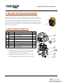
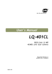
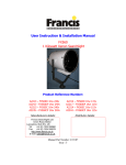
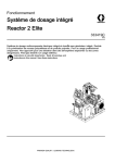
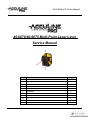
40-6670/40-6675 Service Manual 40-6670/40-6675 Multi-Point Laser Level Service Manual Item Prepared By: Tim Wojo Description Pages 1.0 Overall Instrument Assembly 2 1.1 Main Assembly 2 1.2 Instrument Body Assembly 3 1.3 Core Module Assembly 4 1.4 Laser Assembly 4 2.0 Calibration 2.1 Laser Assembly Calibration 2.2 Overall Instrument Calibration 2.3 Alarm Calibration 6 3.0 Electrical Connections 7 4.0 Trouble Shooting Guide 7 5-6 Revision: 0-052909 5 5-6 Page 1 of 7 40-6670/40-6675 Service Manual 1. Overall Instrument Assembly This Multi-Point Laser level is a highly accurate instrument. Out side of a few customer adjustments (outlined in the owners manual), all adjustments/service operations are internal to the instrument and to be performed only by authorized service personnel. Authorized personnel should adhere to the guidelines described within this service manual for all repairs and/or service work. It should be note that procedures in this manual should be referred to based on the specific situation. 1.1 Main Assembly (40-6670/75) 1. Remove rubber cover 3 (1), Rubber cover 1 (5), and Rubber cover 2 Item 2. 3. 4. 5. 6. 1 2 3 4 4 5 6 JLT Part Description Qty (7) by gently pulling and twisting until parts come off. AP2044 Housing Assembly 1 Remove Horizontal Lock Knob (3) by continually turning counter AP2045 2-1 lens (40-6675) 1 clockwise until screw comes out. AP2052 2.2 Cover Plate (40-6670) 1 Remove AP2046 Lens Frame 1 xxx AP2047 40-6670 Instrument Body Assembly 1 xxx AP2047-1 40-6675 Instrument Body Assembly 1 Remove the Telescope Assembly (6) from the Base Assembly (8) by AP2053 ST2.2x9.5 Crosshead Self-Taping Screw 4 removing retaining screw (11), wave gasket (9), and gasket (10) AP2048 Optical Wedge 1 7 AP2049 Optical Wedge base 1 1. Remove Housing Assembly (1) by loosening 4 retaining screws. 2. Lense frame (3) and Lense/Cover Plate (2) are pressed/glued in place and normally would not have to be replaced. 3. Optical Wedge (6) and Optical Wedge base (7) is pressed in place and calibrated/glued as described in section 2.2 of this document Prepared By: Tim Wojo Revision: 0-052909 Page 2 of 7 40-6670/40-6675 Service Manual 1.2 Instrument Body Assembly (AP2047) Item JLT Part Description Qty 4.1 AP1843 ST2.2x 6.5 Cross Plate Self Tapping 4 Screw 4.2 AP2054 1# Control PCB 1 4.3 AP2053 ST2.2x 9.5 Cross Plate Self Tapping 7 Screw 4.4 AP2055 Connecting Seat 1 4.5 AP2056 Press Spring 2 4.6 AP1491 M2x8 Cross Plate Screw 1 4.7 AP2057 Slip Bracket 1 4.8 AP2058 On/Off Switch 1 4.9 AP2059 Moving Shaft 1 4.10 AP2060 C-ring 1 4.11 AP2061 Block 1 4.12 AP1493 M2.5x8 Cross Plate Screw 2 4.13 AP2062 Supporting Board 1 4.14 AP2063 Bottom Seat Assembly 1 4.15 AP2064 Battery Cover 1 4.16 AP2065 Magnet Plate 4 4.17 AP2066 Magnetic Dampening Magnets 4 4.18 AP2067 Magnet 2 ON/OFF switch (4.8), then remove 2 retaining screws 4.19 AP2068 Bracket 1 (4.1). 4.20 AP2050 40-6670 Core Module 1 4.20 AP2050-1 40-6675 Core Module 1 4.21 AP2069 2# Alarm PCB 1 4.22 AP2070 Brass Retaining washers 2 by loosening 2 retaining screws (4.23) with Brass 4.23 AP1464 M2x6 Cross Plate Screw 2 retaining washers (4.22). 4.24 AP2071 Bracket 1 4.25 AP2072 ST2.2x 6.5 “Sunk” Cross Plate Self 2 1. Remove 1# Control PCB (4.2) from Connecting Seat (4.4) using electric soldering iron. Detach 2 hair spring wires that connect 1# Control PCB (4.2) to Core Module (4.20) and 2 wires that connect 1# Control PCB (4.2) to 2. Remove Alarm Bracket (4.24) from Connecting Seat (4.4) by loosening 2 retaining screws (4.25). 3. Remove2# Alarm PCB (4.21) from Alarm Bracket (4.24) 4. Remove Core Module (4.20) by removing 4 retaining Tapping Screw screws (4.3) from Connecting Seat (4.4). Gently lift core module out, taking care not to damage any of the locking 4.26 AP2073 Sleevelets 2 components with in the Bottom Seat Assembly (4.14). 4.27 AP2074 Rubber Gasket 3 5. After removing Core Module (4.20), remove 2 Press Springs (4.5), and Slip Bracket (4.7)/ON/OFF Switch (4.8). 6. Remove Bottom Seat Assembly (4.14) by removing 3 retaining screws (4.3). 7. Remove Battery Cover (4.15), 2 Magnets (4.18), 4 magnet Plate (4.16), and 4 Magnetic Dampening Magnets (4.17). 8. Remove Compensator Lock Assembly from Bottom Seat assembly (4.14) by loosening 2 retaining screws (4.12). The Compensator Lock Assembly is made up of the following components: Prepared By: Tim Wojo Support Board (4.13), C-ring (4.10), Block (4.11), and Moving Shaft (4.9). Revision: 0-052909 Page 3 of 7 40-6670/40-6675 Service Manual 1.3 Core Module Assembly (AP2050) Item JLT Part Description Qty 4.20.1 AP2051 40-6670 Laser Assembly 1 4.20.1 AP2051-1 40-6675 Laser Assembly 1 4.20.2 AP1475 M2x5 Cross Plate Screw 1 4.20.3 AP1696 M2x10 Cross Plate Screw 2 4.20.4 AP2075 3# Switch PCB 1 4.20.5 AP2076 Compensator Weight (qty varies with need) 1 4.20.6 AP2077 Special Screw 1 2 4.20.7 AP2078 Rubber O-ring 1 4.20.8 AP2079 M6x16 Inner Hexagon Set Screw 6 (4.20.13) by loosening retaining screw (4.20.2) and 4.20.9 AP2080 Weight Ring (qty varies with need) 1 de-soldering wire that connects 3# switch PCB (4.20.4) 4.20.10 AP2081 M3x4 Inner Hexagon Set Screw 1 to Alarm Spring (4.20.11). 4.20.11 AP2082 Alarm Spring 1 4.20.12 AP2083 Connecting Shaft 1 4.20.13 AP2084 Gimbal Assembly 1 1. Remove 3# switch PCB (4.20.4) from Gimbal Assembly 2. Remove Weight Pieces (4.20.5) from Gimbal Assembly (4.20.13) by loosening 2 retaining screw (4.20.3). 3. Remove Weight Loops (4.20.9) from Laser Assembly (4.20.1) by loosening retaining set screws (4.20.10). 4. Remove Laser Assembly (4.20.1) by loosening 2 retaining screws (4.20.6). 5. Remove Alarm Spring (4.20.11) by rotating the connecting shaft (4.20.12) counter-clockwise until it comes out. 6. Remove 6 Counter Balance set screws (4.20.8) from Gimbal Assembly (4.20.13) by loosening counter-clockwise until they come out. These screws have a special lock-tight applied to prevent movement through shipment. We sure to reapply this after calibration adjustment are made. 1.4 Laser Assembly (AP2051) Item JLT Part Description Qty 4.20.1.1 AP1491 M2x8 Cross Plate Screw 4 4.20.1.2 AP2085 Laser Module 1 4.20.1.3 AP2086 Adjusting Base 1 4.20.1.4 AP2087 4.20.1.4.1 Trapezoidal Prism 1 (40-6675) AP2088 4.20.1.4.2 Trapezoidal Prism 1 (40-6670) 4.20.1.5 AP2089 Prism Seat 1 4.20.1.6 AP2090 M2x12 Cross Plate “Sunk” Screw 2 1. Remove the Prism (4.20.1.4.1 or 4.20.1.4.2) and Prism Seat (4.20.1.5) from Adjusting Base (4.20.1.3) by loosening 2 retaining screws (4.20.1.6). 2. Remove Laser Module (4.20.1.2) from Adjusting Base (4.20.1.3) by loosening 4 retaining screws (4.20.1.1) Prepared By: Tim Wojo Revision: 0-052909 Page 4 of 7 40-6670/40-6675 Service Manual 2.0 Calibration Calibration is a process that is used to correct for accuracy and/or functional errors above and beyond those stated in published specifications. This product is fairly easy to verify and calibrate as there are only a few adjustments that can be made. Each item discussed is shown below. 2.1 Laser Assembly Calibration: The Laser Assembly (4.20.1) must be calibrated external to the unit on a customized test stand. test stand is shown to the right. The Note that the center of the stand is 10m from the furthest reference point. In the illustration points “A and B” are reflected plumb up and plumb down beams. beam. The location and range of reference point Point “O” is the front Horizontal error of the test stand should be less than 5’. Accuracy of reference heights (for points A, B, and O) should be no less than 0.05mm/m. The calibration method describe below is the same for both the 40-6670 and 40-6675, just omit the front point for the 40-6670. 1. Install the Laser Assembly to be calibrated in the test stand fixture. 2. Adjust plane E to be horizontal to the test stand using the 3 adjustment wheels located on clamping fixture F. An auto level can be used to add in leveling the stand. 3. Apply power (4.5Vdc) to the Laser Assembly. 4. Using adjustment screws 4.20.1.1 (qty 4) and 4.20.1.6 (qty2), adjust output laser spots A, B and O to coincide with their respective reference points. point O is the reference point. Note that Points A and B should be in the range defined above (within 1mm from center). 2.2 Overall Instrument Calibration: Now that the laser assembly has been calibrated and reinstalled in the overall assembly, the compensator and optics must be calibrated. method is the same for the 40-6670 and 40-6675. no front point to calibrate on the 40-6670. Note that the calibration The only difference is that there is The calibration method is described below. Prepared By: Tim Wojo Revision: 0-052909 Page 5 of 7 40-6670/40-6675 Service Manual 1. Place instrument to be calibrated on test stand. 2. Power laser and aim dot at reference (Point “O” as Adjusting screw described above) 3. Fine adjusting screw Observe the offset between the three points and their Compensator Weight respective references. If the offset is less than 20mm (which is the diameter of the circle, while the reference point is in the center of the circle), adjust as defined in step 4. Otherwise adjust as defined in step 5. Note: observe whether there is offset between front point and reference point on adjacent light ruler. If there is, the offset between further reference point and the corresponding reference line will be the same distance. Please note this problem during the following adjustment. Fine 4. Adjust 6 Counter Balance screws (4.20.8) to adjust plumb up accordingly. adjusting Adjusting the three screws on the side of the instrument will cause the screw plumb up to move left or right, respectively. Adjusting the three screws on the front will cause it to move down to move up or down, respectively. Finally, the optical wedge (7) is adjusted for final plumb down calibration. The wedge is tapered, so rotating will cause the plumb down to rotating in an elliptical pattern. 5. Adjust it accordingly. If the offset between the three points and their reference is greater than 20mm, compensator weights (4.20.5) or weight rings (4.20.9) need to be added or subtracted based on the need. point, the offset need not to be adjusted. If the up point is on the position of horizontal direction of front The adjustment can be made by re-aligning the laser assembly, i.e. adjustment screws 4.20.6 (remembering to loosen one while tightening the other). screws 4.20.3. A similar adjustment could be made by adjusting adjustment Proceed to step 4 as needed. 2.3 Alarm Calibration: This is accomplished by centering the alarm spring (4.20.11) with in the alarm ring on the alarm PCB (4.21). 1. With the instrument on a level test stand, loosen 2 adjustment screws (4.23) and center the Alarm PCB (4.23) around the Alarm Spring (4.20.11). 2. Adjusting Tighten the adjustment 2 screws (4.23). screw Note: The instrument should alarm 2.3° and any direction from level Prepared By: Tim Wojo Revision: 0-052909 Page 6 of 7 40-6670/40-6675 Service Manual 3.0 Electrical Connections Leading line of battery box Laser source Hair ON/OFF switch 4.0 Trouble Shooting Guide No. Symptom 1 2 Cause Battery is low No Power Broken battery wire Corrective Action Replace batteries(3XAA) Repair/Replace wiring ON/OFF switch is broken/connected line is 3 cut off Repair/Replace ON/OFF switch 4 1# main circuit board is defective Repair/ Replace 1# main circuit board 5 Indicator doesn’t light when power Indicator is defective Replace indicator 6 is on 1# main circuit board is defective Replace 1# main circuit board 7 Hair spring is damaged Replace hair spring Connected line of 3# circuit board is 8 No laser output damaged/devfective Repair connected line 9 1# main circuit board is defective Replace 1# main circuit board 10 Laser indicator is damaged or defective Replace laser source 11 Buzzer is damaged or defective Replace buzzer 12 No sound if tilt beyond range Connected line of 1# & 2# circuit board is damaged/defective Repair connected line 13 1# main circuit board is damaged/defective Replace 1# main circuit board 14 1# main circuit board is damaged/defective Replace 1# main circuit board No alarming if tilt beyond range 15 Prepared By: Connected line of 1# & 2# circuit board is damaged/defective Tim Wojo Revision: 0-052909 Repair connected line Page 7 of 7