1
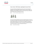
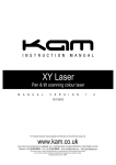
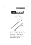
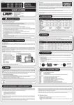
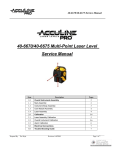
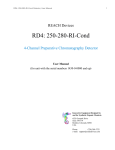
Owner’s Manual
Model
AP1020/AP2090/AP2130
STEREO POWER AMPLIFIER
CAUTION
RISK OF ELECTRIC SHOCK
DO NOT OPEN
CAUTION: TO REDUCE THE RISK OF ELECTRIC SHOCK,
DO NOT REMOVE COVER (OR BACK).
NO USER - SERVICEABLE PARTS INSIDE.
CAUTION:
TO PREVENT ELECTRIC SHOCK, MATCH WIDE
BLADE OF PLUG TO WIDE SLOT, FULLY INSERT.
ATTENTION:
POUR EVITER LES CHOCS ELECTRIQUES,
INTRODUIRE LA LAME LA PLUS LARGE DE LA
FICHE DANS LA BORNE CORRESPONDANTE DE
LA PRISE ET POUSSER JUSQU AU FOND.
The lighting flash with arrowhead symbol, within an
equilateral triangle, is intended to alert the user to the
presence of uninsulated "dangerous voltage" within the
product's enclosure that may be of sufficient magnitude to
constitute a risk of electric shock to persons.
REFER SERVICING TO QUALIFIED SERVICE PERSONNEL.
"WARNING"
The exclamation point within an equilateral triangle is
intended to alert the user to the presence of important
operating and maintenance (servicing) instructions in the
literature accompanying the appliance.
"TO REDUCE THE RISK OF FIRE OR ELECTRIC
SHOCK, DO NOT EXPOSE THIS APPLIANCE TO RAIN
OR MOISTURE."
SAFETY INSTRUCTIONS
1. Read Instructions - All the safety and operating
instructions should be read before the appliance is
operated.
2. Retain Instructions - The safety and operating
instructions should be retained for future reference.
3. Heed Warnings - All warnings on the appliance and
in the operating instructions should be adhered to.
4. Follow Instructions - All operating and use
instructions should be followed.
5. Water and Moisture - The appliance should not be
used near water - for example, near a bathtub,
washbowl, kitchen sink, laundry tub, in a wet
basement, or near a swimming pool, and the like.
6. Carts and Stands - The appliance should be used
only with a cart or stand that is recommended by the
manufacturer.
7.
8.
9.
10.
11.
12.
An appliance and cart combination should be moved
with care. Quick stops, excessive force, and uneven
surfaces may cause the appliance and cart combination
to overturn.
Wall or Ceiling Mounting - The appliance should be
mounted to a wall or ceiling only as recommended by
the manufacturer.
Ventilation - The appliance should be situated so that
its location or position does not interfere with its
proper ventilation. For example, the appliance should
not be situated on a bed, sofa, rug, or similar surface
that may block the ventilation openings; or, place in a
built-in installation, such as a bookcase or cabinet
that may impede the flow of air through the
ventilation openings.
Heat - The appliance should be situated away from
heat sources such as radiators, heat registers,
stoves, or other appliances (including amplifiers) that
produce heat.
Power Sources - The appliance should be connected
to a power supply only of the type described in the
operating instructions or as marked on the appliance.
Grounding or Polarization - The precautions that
should be taken so that the grounding or polarization
means of an appliance is not defeated.
Power Cord Protection - Power supply cords should
be routed so that they are not likely to be walked on
13.
14.
15.
16.
or pinched by items placed upon or against them,
paying particular attention to cords at plugs,
convenience receptacles, and the point where they exit
from the appliance.
Cleaning - The appliance should be cleaned only as
recommended by the manufacturer.
Nonuse Periods - The power cord of the appliance
should be unplugged from the outlet when left unused
for a long period of time.
Object and Liquid Entry - Care should be taken so that
objects do not fall and liquids are not spilled into the
enclosure through openings.
Damage Requiring Service - The appliance should be
serviced by qualified service personnel when:
A. The power supply cord or the plug has been damaged; or
B. Objects have fallen, or liquid has been spilled into the
appliance;
or
C. The appliance has been exposed to rain; or
D. The appliance does not appear to operate normally or
exhibits a marked change in performance; or
E. The appliance has been dropped, or the enclosure damaged.
17. Servicing - The user should not attempt to service
the appliance beyond that described in the operating
instructions. All other servicing should be referred to
qualified service personnel.
18. The appliance should be situated away from drops
of water or spray of water.
19. Objects containing liquid such as vase must not be
put on the appliance.
The appliance is not completely isolated from the
20. power supply even if the power switch is at off
position.
21. Apparatus shall not be exposed to dripping or
splashing and no objects filled with liquids, such as
vases, shall be placed on the apparatus.
22. Only use attachments/accessories specified by the
manufacturer.
23. An appliance with a protective earth terminal should
be connected to mains outlet with a protective earth
connection.
24. An appliance should be placed in a position where
an AC plug / inlet can be easily pulled out by hand.
25. Main plug is used as the disconnection device. It
shall remain readily operable and should not be
obstructed during intended use. To be completely
disconnected the apparatus from supply mains, the
main plug of the apparatus shall be disconnected
from the mains socket outlet completely.
INTRODUCTION
Fostex new AP Series amplifiers AP1020, AP1020, AP2090 and AP2130
are designed to withstand severe operating conditions.
It is a commercial use amplifier containing high technology
citcuits designed for stability, durability, small size and
large output.
Contents
Controls and connections (Model AP2090/AP2130)..................................2
Controls and Connections (Model AP1020)..............................................3
Outstanding features................................................................................4
Crossover network, selector switch..........................................................5
Multi–amplfier system examples using AP2090/2130................................6
Block diagram..........................................................................................7
Specifications..........................................................................................8
—1—
AP2090/AP2130
FRONT PANEL
REAR PANEL
1.
2.
3.
4.
5.
6.
7.
8.
9.
10.
11.
12.
13.
14.
Power switch
Power indicator
Output level controller
Output level indicator
Clip indicator
Thermal indicator
Compressor / limiter indicator
Handle
Filter cover
15.
16.
17.
18.
19.
20.
—2—
Input connector
Crossover mode (VR)
Crossover mode (Selector)
MONO/STEREP selector SW
Crossover network output
(HIGH)
Crossover network output
(LOW)
COMP/L switch
Speaker output
Cooling fan
Power cord
Power supply fuse
AP1020
FRONT PANEL
REAR PANEL
1.
2.
3.
4.
5.
6.
7.
8.
9.
Power switch
Power indicator
Output level controller
Output level indicator
Clip indicator
Thermal indicator
Compressor / limiter indicator
Handle
Filter cover
10.
11.
12.
13.
14.
15.
16.
17.
—3—
AC (Input)
MONO/STEREO switch
Fuse
Cooling fan
Compressor / limiter switch
Input connector
Output connector CH-1
"
"
CH-2
OUTSTANDING FEATURES
1) Forced cooling
When the amplifier internal temperature rises, thee cooling
fan automatically changes to high speed to force cool the
heat sink for protecting the amplifier.
2) Level indicator (AP2090, AP2130)
This LED is lit in 5dB steps over the 0 ~ - 30dB range to
check the input signal.
3) Clip indicator
This LED is lit at overload. It will flash on large instantaneous inputs but will not pose any problems.
4) Thermal indicator
When this LED is lit, it indicates that the amplifier internal temperature is unusually high, and the power supply
voltage is reduced automatically to control the amplifier
output.
Consequently, you may notice some distortion when this LED
is lit as the amplifier output has been reduced.
5) Crossover network circuit (AP2090, AP2130)
These contain a 2 way crossover network continuously variable over 30Hz ~ 2,000Hz at an 18dB/octave slope.
6) Crossover network OUTPUT connector (HIGH, LOW; AP2090 and
AP2130 only)
This output connector allows multi system use with a 2 way
or 3 way speaker system (Refer to Multi System Examples,
page 6) and HIGH PASS/LOW PASS outputs can be obtained from
each output connector.
7) Compressor/limiter circuit
Individual compressor / limiter circuits for each channel are
contained which can be made to function by the rear panel ON
/ OFF selector switch. The limiter can be switched ON / OFF by
the rear panel COMP / L switch. The compressor operates at a
compressinon ratio of 2, from about 1/2 of rated output up to
clipping output, after which the hard limiter functions to
suppress distortion. Consequently, when the limiter is
switched on, the output will not largely distort even at excess input.
—4—
CROSSOVER NETWORK, SELECTOR SWITCH
1) FULL
At this position, the crossover network is bypassed, (Hz)
control pot becomes ineffective, a flat response output
against the input signal is obtained at the output connector. The crossover network outputs (HIGH, LOW) at each connector will be those set by the crossover frequency adjustinig knobs.
2) HIGH
When this position is selected, the HIGH PASS signal whose
cutoff frequency is set by the (Hz) knob, is obtained at the
speaker output connector.
3) LOW
When set to this position, the LOW PASS signal whose cutoff
frequency is set by the (Hz) knob, is obtained at the speaker output connector.
INPUT CONNECTION
Two types of connectors, XLR3-31 equivalent and 1/4" 3P
phone jack, both of balanced line are wired in parallel.
Polarity of the pins are as follows:
(#1 pin) • • • Ground, (#2 pin) • • • Hot, (#3 pin) • • • Cold
For the stereo mode, the rear panel MODE selector switch is
set to STEREO and the left input is connected to INPUT (1) and
the right input to INPUT (2).
For the mono mode, the selector switch is set to MONO and
the input signal is applied between ground and INPUT (1).
2
3
1
CANNON
PHONE
BALANCED
HOT
—5—
3
2
1
MULTI-AMPLIFIER SYSTEM EXAMPLE USUNG AP2090/2130
[Example of 2 way system]
AMP 1 (HIGH PASS AMP)
INPUT
INPUT
FULL
HIGH
H
H.SP
LOW
L
HIGH OUT
LOW OUT
AMP 2 (LOW PASS AMP)
INPUT
FULL
HIGH
H
L.SP
LOW
L
HIGH OUT
LOW OUT
[Example of 3 way system]
AMP 1 (HIGH PASS AMP)
FULL
INPUT
HIGH
H
H.SP
LOW
L
HIGH OUT
LOW OUT
AMP 2 (BAND PASS AMP)
INPUT
FULL
HIGH
M.SP
H
LOW
L
HIGH OUT
LOW OUT
AMP 3 (LOW PASS AMP)
FULL
INPUT
H
L
HIGH
LOW
HIGH OUT
LOW OUT
—6—
L.SP
* General use amplifiers not containing a crossover network can
also be used for the low region or high region amplifier.
When Ap20909/2130 are to be used as a full range amplifier,
harmful sub-sonic frequencies can be cut off if the crossover
network selector switch is set to HIGH and crossover frequency
to 30Hz.
If a line transformer is to be connected, always set to HIGH
PASS (crossover network selector switch to HIGH) and crossover
frequency to 100Hz.
The speaker low region cutoff frequency will slightly change
depending on the line transformer used.
Block diagram
CLIP
CLIP
SENSER
IN
DC & LF
SENSER
HA
HPF
LPF
COMP / LIMIT
LPF
PA
OUT
ON / OFF
H. OUT
LOAD
IMPEDANCE
SENSER
L. OUT
PEAK LEVEL
IND.
-30 ~ 0dB
THERMAL
SENSER
MONO
STEREO
HIGH
LOW
POWER SUPPLY
M
THERMAL
IND.
FAN MOTOR
M
CHANNEL 2
—7—
Circuit inside
dotted square
not included in
Model AP1020
SPECIFICATIONS
AP1020
AP2090
75W+75W. . . . 8Ω
100W+100W. . . 8Ω
200W(mono). . . 8Ω
300W+300W. . . 8Ω
450W+450W. . . 4Ω
900W(mono). . . 8Ω
AP2130
[AMPLIFIER SECTION]
Rated output
Total
harmonic
distortion
(At 1kHz
rated output)
Reproduce
frequnecy
range
S/N ratio
Input
impedance
Damping
factor
Less than
0.05%
Less than
0.05%
Less than
0.05%
10 ~ 35,000Hz
(At rated output, +0dB,
-1dB)
10 ~ 35,000Hz
(At rated output, +0dB,
-1dB)
10 ~ 35,000Hz
(At rated output, +0dB,
-1dB)
92dB (IHF-A,
100dB)
100dB (IHF-A,
105dB)
100dB (IHF-A,
105dB)
10kΩ
10kΩ
10kΩ
Higher than
300 (8Ω)
(
1kHz
)
0.70V
(±1dB, 8Ω)
Higher than
350 (8Ω)
(
1kHz
)
1.40V
(±1dB, 8Ω)
Higher than
400 (8Ω)
(
1kHz
)
1.72V
(±1dB, 8Ω)
30 ~ 2,000Hz
(18dB/oct.)
30 ~ 2,000Hz
(18dB/oct.)
482x88x435
482x88x435
Input sensitivityt (At
rated output)
[ CROSSOVER NETWORK SECTION ]
Crossover
frequency
Dimensions (mm)
(in mm)
(W) x (H) x (D)
482x43.5x422
Weight
8.1kg
Power supply
Power
consumption
AC
AC
AC
450W+450W. . . 8Ω
650W+650W. . . 4Ω
1300W(mono). . 8Ω
120V/AC
220V/AC
240V/AC
100V
215W
120V
210W
220/
550VA
240V
22.6kg
23.0kg
120V/AC
220V/AC
240V/AC
630W
955W
2KVA
120V/AC
220V/AC
240V/AC
745W
1150W
2.28kVA
Specifications in this manual subject to change for improvement without notice.
Above specifications as of September 30, 1989.
PRO SOUND DIVISION
FOSTEX COMPANY 3-2-35 Musashino, Akishima, Tokyo, Japan 196-0021
* Specifications subject to change without notice.
© PRINTED IN JAPAN FFR. 1990 8629000301 SG