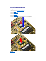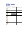
1
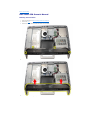
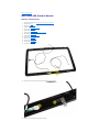
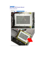
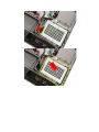
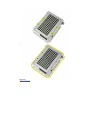
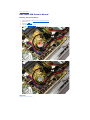
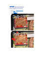
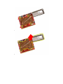
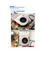
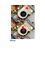
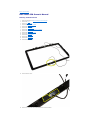
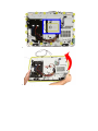
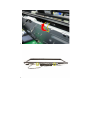
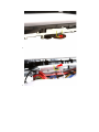
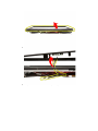
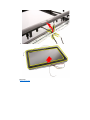
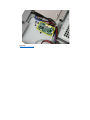
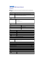
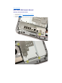
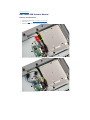
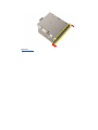
Dell™ Vostro™ 330
PDF
Setup and Features Information Tech Sheet
Owner's Manual
Regulatory Information
Regulatory Compliance
Regulatory Model: W02C
Regulatory Type: W02C001
Last revised: 7 June 2011
View
HTML
Download
View
Download
Back to Contents Page
Dell Vostro 330 Owner's Manual
Speaker Cover
Installing The Speaker Cover
Removing The Speaker Cover
Back to Contents Page
Dell Vostro 330 Owner's Manual
Heat Sink
Removing The Processor Heat Sink
Removing The Processor Heat Sink
Back to Contents Page
Dell Vostro 330 Owner's Manual
Front Bezel
Removing The Front Bezel
Installing The Front Bezel
Back to Contents Page
Dell Vostro 330 Owner's Manual
Removing The Back Stand Cover
1.
Follow the procedures in Before Working Inside Your Computer.
2.
Remove the cover.
3.
Remove the front stand.
4.
Push the back stand to its maximum extent.
5.
Slide the stand cover through the stand and remove the back stand cover from the computer.
Related tasks
Installing The Back Stand Cover
Back to Contents Page
Dell Vostro 330 Owner's Manual
Installing The Speakers
1.
Place the speakers on the system board.
2.
Replace the screws that secure the speakers to the system board.
3.
Connect the speaker cable to the system board.
4.
Replace the system board shield.
5.
Replace the front stand.
6.
Replace the cover.
7.
Follow the procedures in After Working Inside Your Computer.
Related tasks
Removing the Speakers
Back to Contents Page
Dell Vostro 330 Owner's Manual
Removing The Front Stand
1.
Follow the procedures in Before Working Inside Your Computer.
2.
Remove the cover.
3.
Remove the screws that secure the front stand to the computer.
4.
Fold the back stand as far as it will go and then lift the front stand out of the computer.
5.
Remove the screws securing the I/O bracket to the front stand.
6.
Remove the I/O panel.
Related tasks
Installing The Front Stand
Back to Contents Page
Dell Vostro 330 Owner's Manual
System Board Shield
Removing The System Board Shield
Installing The System Board Shield
Back to Contents Page
Dell Vostro 330 Owner's Manual
Removing The Processor Heat Sink
1.
Place the heat sink on the computer and replace the screws that secure the heat sink to the system board.
2.
Replace the screws that secure the heat sink to the computer.
3.
Replace the processor fan.
4.
Replace the video card fan.
5.
Replace the video card and heat sink assembly.
6.
Replace the system board shield.
7.
Replace the front stand.
8.
Replace the cover.
9.
Follow the procedures in After Working Inside Your Computer.
Related tasks
Removing the Processor Heat Sink
Back to Contents Page
Dell Vostro 330 Owner's Manual
Installing The Antenna
1.
Place the antenna on its location on the chassis and paste it to the chassis using the metal tape.
2.
Turn the chassis over. Paste the cables using the metal tape.
3.
Replace the screws that secure the antenna to the chassis.
4.
Route the cables through the routing slots, and engage the cables to the clips.
5.
Replace the front bezel.
6.
Replace the middle bezel.
7.
Replace the processor.
8.
Replace the processor heat sink.
9.
Replace the processor fan.
10.
Replace the video card fan.
11.
Replace the video card and heat sink assembly.
12.
Replace the system board shield.
13.
Replace the front stand.
14.
Replace the cover.
15.
Follow the procedures in After Working Inside Your Computer.
Related tasks
Removing the Antenna
Back to Contents Page
Dell Vostro 330 Owner's Manual
Removing The Web Camera
1.
Follow the procedures in Before Working Inside Your Computer.
2.
Remove the cover.
3.
Remove the front stand.
4.
Remove the system board shield.
5.
Remove the WLAN card.
6.
Remove the video card fan.
7.
Remove the video card and heat sink assembly.
8.
Remove the processor fan.
9.
Remove the processor heat sink.
10.
Remove the processor.
11.
Remove the system board.
12.
Remove the middle bezel.
13.
Remove the front bezel.
14.
Locate the camera board.
15.
Remove the screws that secure the camera board to the front bezel.
16.
Remove the camera board along with the cable.
Related tasks
Installing The Web Camera
Back to Contents Page
Dell Vostro 330 Owner's Manual
Optical Drive
Removing The Optical Drive
Installing The Optical Drive
Back to Contents Page
Dell Vostro 330 Owner's Manual
Installing The Convertor Board
1.
Place the convertor board on the computer.
2.
Replace the screws that secure the convertor board to the computer.
3.
Connect the display and power cables to the convertor board.
4.
Replace the cover.
5.
Follow the procedures in After Working Inside Your Computer.
Related tasks
Removing the Convertor Board
Back to Contents Page
Dell Vostro 330 Owner's Manual
System Setup Screens
Menu — Appears on top of the System Setup window. This field provides a menu to access the System Setup options.
Press < Left Arrow > and < Right Arrow > keys to navigate. As a Menu option is highlighted, the Options List lists the
options that define the hardware installed on your computer.
Options
List —
Appears on
the left side
of the
System
Setup
window. The
field lists
features that
define the
configuration
of your
computer,
including
installed
hardware,
power
conservation,
and security
features.
Scroll up and
down the list
with the upand downarrow keys.
As an option
is
highlighted,
the Options
Field
displays the
option's
current and
available
settings.
Options Field — Appears on the right side of Options List and contains information
about each option listed in the Options List . In this field you can view information about
your computer and make changes to your current settings. Press < Enter> to make
changes to your current settings. Press <ESC> to return to the Options List .
NOTE: Not all settings listed in the Options Field are changeable.
Help —
Appears
on the
right side
of the
System
Setup
window
and
contains
help
information
about the
option
selected in
Options
List .
Key Functions — Appears below the Options Field and lists keys and their functions within the active system setup
field.
Use the following keys to navigate through the System Setup screens:
Keystroke
Action
< F2 >
Displays information on any selected item in the System Setup.
< Esc >
Exit from current view or switch the current view to the Exit page in the System
Setup.
< Up Arrow > or < Down Arrow
>
Select an item to display.
< Left Arrow > or < Right Arrow
>
Select a menu to display.
– or +
< Enter >
< F9 >
< F10 >
Change existing item value.
Select the sub menu or execute command.
Load setup default.
Save current configuration and exit System Setup.
Back to Contents Page
Dell Vostro 330 Owner's Manual
Before Working Inside Your Computer
Use the following safety guidelines to help protect your computer from potential damage and to help to ensure your
personal safety. Unless otherwise noted, each procedure included in this document assumes that the following
conditions exist:
l
You have read the safety information that shipped with your computer.
l
A component can be replaced or--if purchased separately--installed by performing the removal procedure in
reverse order.
WARNING: Before working inside your computer, read the safety information that shipped with your
computer. For additional safety best practices information, see the Regulatory Compliance Homepage at
www.dell.com/regulatory_compliance.
CAUTION: Many repairs may only be done by a certified service technician. You should only perform
troubleshooting and simple repairs as authorized in your product documentation, or as directed by the online
or telephone service and support team. Damage due to servicing that is not authorized by Dell is not covered
by your warranty. Read and follow the safety instructions that came with the product.
CAUTION: To avoid electrostatic discharge, ground yourself by using a wrist grounding strap or by
periodically touching an unpainted metal surface, such as a connector on the back of the computer.
CAUTION: Handle components and cards with care. Do not touch the components or contacts on a card. Hold
a card by its edges or by its metal mounting bracket. Hold a component such as a processor by its edges, not
by its pins.
CAUTION: When you disconnect a cable, pull on its connector or on its pull-tab, not on the cable itself. Some
cables have connectors with locking tabs; if you are disconnecting this type of cable, press in on the locking
tabs before you disconnect the cable. As you pull connectors apart, keep them evenly aligned to avoid
bending any connector pins. Also, before you connect a cable, ensure that both connectors are correctly
oriented and aligned.
NOTE: The color of your computer and certain components may appear differently than shown in this document.
To avoid damaging your computer, perform the following steps before you begin working inside the computer.
1.
Ensure that your work surface is flat and clean to prevent the computer cover from being scratched.
2.
Turn off your computer (see Turning Off Your Computer).
CAUTION: To disconnect a network cable, first unplug the cable from your computer and then unplug
the cable from the network device.
3.
Disconnect all network cables from the computer.
4.
Disconnect your computer and all attached devices from their electrical outlets.
5.
Press and hold the power button while the computer is unplugged to ground the system board.
6.
Remove the cover.
CAUTION: Before touching anything inside your computer, ground yourself by touching an unpainted
metal surface, such as the metal at the back of the computer. While you work, periodically touch an
unpainted metal surface to dissipate static electricity, which could harm internal components.
Back to Contents Page
Dell Vostro 330 Owner's Manual
Installing The Bluetooth Card
1.
Place the Bluetooth card at it's location on the front bezel.
2.
Replace the screws that secure the Bluetooth card to the front bezel.
3.
Replace the Mylar cover.
4.
Replace the front bezel.
5.
Replace the system board.
6.
Replace the processor heat sink.
7.
Replace the processor fan.
8.
Replace the video card fan.
9.
Replace the video card and heat sink assembly.
10.
Replace the WLANC.
11.
Replace the system board shield.
12.
Replace the front stand.
13.
Replace the cover.
14.
Follow the procedures in After Working Inside Your Computer.
Related tasks
Removing the Bluetooth Card
Back to Contents Page
Dell Vostro 330 Owner's Manual
Removing The WLAN Card
1.
Follow the procedures in Before Working Inside Your Computer.
2.
Remove the cover.
3.
Remove the front stand.
4.
Remove the system board shield.
5.
Disconnect the antenna cables.
6.
Remove the screws that secure the WLAN card to the computer.
7.
Pull the WLAN card out and remove it from the computer.
Related tasks
Installing the WLAN Card
Back to Contents Page
Dell Vostro 330 Owner's Manual
Speaker
Removing The Speakers
Installing The Speakers
Back to Contents Page
Dell Vostro 330 Owner's Manual
Contacting Dell
To contact Dell for sales, technical support, or customer service issues:
1.
Visit support.dell.com.
2.
Verify your country or region in the Choose a Country/Region drop-down menu at the bottom of the page.
3.
Click Contact Us on the left side of the page.
4.
Select the appropriate service or support link based on your need.
5.
Choose the method of contacting Dell that is convenient for you.
Back to Contents Page
Dell Vostro 330 Owner's Manual
Installing The Display Panel
1.
Route all the cables through their routing slots.
2.
Place the display panel on the frame.
3.
Replace the screws that secure the display panel to the chassis.
4.
Route the IR and Bluetooth cables through their respective routing holes.
5.
Press the bezel on to the display till all the tabs snap into place.
6.
Replace the web camera.
7.
Carefully turn the assembly over.
8.
Replace the screws that secure the front bezel to the chassis.
9.
Route the IR cable and camera cable thorough their routing slots.
10.
Connect the camera cables to the DSP board.
11.
Connect the display power cable to the converter.
12.
Route the Bluetooth cable through the routing slot.
13.
Replace the front bezel.
14.
Replace the middle bezel.
15.
Replace the processor.
16.
Replace the processor heat sink.
17.
Replace the processor fan.
18.
Replace the video card fan.
19.
Replace the video card and heat sink assembly.
20.
Replace the system board shield.
21.
Replace the front stand.
22.
Replace the cover.
23.
Follow the procedures in After Working Inside Your Computer.
Related tasks
Removing the Display Panel
Back to Contents Page
Dell Vostro 330 Owner's Manual
Notes, Cautions, and Warnings
NOTE: A NOTE indicates important information that helps you make better use of your computer.
CAUTION: A CAUTION indicates potential damage to hardware or loss of data if instructions are not followed.
WARNING: A WARNING indicates a potential for property damage, personal injury, or death.
Back to Contents Page
Dell Vostro 330 Owner's Manual
Working on Your Computer
Before Working Inside Your Computer
Recommended Tools
Turning Off Your Computer
After Working Inside Your Computer
Back to Contents Page
Dell Vostro 330 Owner's Manual
After Working Inside Your Computer
After you complete any replacement procedure, ensure you connect any external devices, cards, and cables before
turning on your computer.
1.
Replace the cover.
CAUTION: To connect a network cable, first plug the cable into the network device and then plug it into
the computer.
2.
Connect any telephone or network cables to your computer.
3.
Connect your computer and all attached devices to their electrical outlets.
4.
Turn on your computer.
5.
Verify that the computer works correctly by running the Dell Diagnostics.
Back to Contents Page
Dell Vostro 330 Owner's Manual
Processor
Removing The Processor
Installing The Processor
Back to Contents Page
Dell Vostro 330 Owner's Manual
Removing The Hard Drive
1.
Follow the procedures in Before Working Inside Your Computer.
2.
Remove the cover.
3.
Loosen the captive screws that secure the hard drive cage to the computer.
4.
Slide the hard drive bracket away from the computer to release the tabs from the computer.
5.
Disconnect the power cable and SATA cable.
6.
Lift the hard drive out of the computer.
7.
Remove the screws that secure the hard drive to the hard drive bracket.
8.
Lift the hard drive bracket from the hard drive.
Related tasks
Installing the Hard Drive
Back to Contents Page
Dell Vostro 330 Owner's Manual
AV Cable
Removing The AV Cable
Installing The AV Cable
Back to Contents Page
Dell Vostro 330 Owner's Manual
Installing The Cover
1.
Place the back cover on the computer.
2.
Slide the back cover towards the stand.
3.
Install the two screws that secure the back cover to the computer.
4.
Follow the procedures in After Working Inside Your Computer.
Related tasks
Removing The Cover
Back to Contents Page
Dell Vostro 330 Owner's Manual
Recommended Tools
The procedures in this document may require the following tools:
l
Small flat-blade screwdriver
l
Phillips screwdriver
l
Small plastic scribe
l
Flash BIOS update program media
Back to Contents Page
Dell Vostro 330 Owner's Manual
Touch-Control Board
Removing The Touch-Control Board
Installing The Touch-Control Board
Back to Contents Page
Dell Vostro 330 Owner's Manual
Removing The Speakers
1.
Follow the procedures in Before Working Inside Your Computer.
2.
Remove the cover.
3.
Remove the front stand.
4.
Remove the system board shield.
5.
Disconnect the speaker cable from the system board.
6.
Remove the screws that secure the speakers to the system board.
7.
Remove the speakers from the system board.
Related tasks
Installing The Speakers
Back to Contents Page
Dell Vostro 330 Owner's Manual
Antenna
Removing The Antenna
Installing The Antenna
Back to Contents Page
Dell Vostro 330 Owner's Manual
Removing The Coin-Cell Battery
1.
Follow the procedures in Before Working Inside Your Computer.
2.
Remove the cover.
3.
Remove the front stand.
4.
Remove the system board shield.
5.
Press the coin-cell battery release tab till the battery pops out.
6.
Remove the coin-cell battery from the socket.
Related tasks
Installing the Coin-Cell Battery
Back to Contents Page
Dell Vostro 330 Owner's Manual
Cover
Removing The Cover
Installing The Cover
Back to Contents Page
Dell Vostro 330 Owner's Manual
Installing The System Board
1.
Replace the thermal pads under the system board.
2.
Replace the two thermal pads under the memory slots.
3.
Replace the screws that secure the system board to the computer.
4.
Replace the mounting post for the video card fan.
5.
Connect the speaker cable.
6.
Connect the five cables.
7.
Connect the two cables.
8.
Tie the cables using a cable clamp for better cable management.
9.
Connect the SATA cables to the system board.
10.
Connect the AV cable to the system board.
11.
Replace the processor heat sink.
12.
Replace the processor fan.
13.
Replace the video card fan.
14.
Replace the video card and heat sink assembly.
15.
Replace the memory.
16.
Replace the system board shield.
17.
Replace the front stand.
18.
Replace the cover.
19.
Follow the procedures in After Working Inside Your Computer.
Related information
Installing the Cover
Back to Contents Page
Dell Vostro 330 Owner's Manual
Removing The MXM Video Card And Heat Sink
1.
Follow the procedures in Before Working On Your Computer.
2.
Remove the cover.
3.
Remove the front stand.
4.
Remove the system board shield.
5.
Remove the video card fan.
6.
Remove the screws that secure the MXM card and heat sink to the system board
The card will pop out at an angle.
7.
Remove the MXM video card and heat sink out of the socket.
8.
Remove the screws that secure the heat sink to the MXM video card.
9.
10.
Pull the heat sink away from the MXM video card.
Pull the MXM video card away from the base plate.
Related tasks
Installing The Video Card and Heat Sink
Back to Contents Page
Dell Vostro 330 Owner's Manual
Thermal Fan
Removing The Processor Fan
Installing The Processor Fan
Back to Contents Page
Dell Vostro 330 Owner's Manual
Contacting Dell
Contacting Dell
Back to Contents Page
Dell Vostro 330 Owner's Manual
Specifications
Specifications
Back to Contents Page
Dell Vostro 330 Owner's Manual
Installing The Middle Bezel
1.
Place the middle bezel on the computer.
2.
Press the middle bezel into the computer till all the tabs snap into place.
3.
Replace the screws that secure the middle bezel to the computer.
4.
Replace the system board shield.
5.
Replace the front stand.
6.
Replace the cover.
7.
Follow the procedures in After Working Inside Your Computer.
Related tasks
Removing the Middle Bezel
Back to Contents Page
Dell Vostro 330 Owner's Manual
Installing The Hard Drive
1.
Place the hard drive bracket on the hard drive.
2.
Replace the screws securing the hard drive to the hard drive bracket.
3.
Place the hard drive on the computer.
4.
Connect the power cable and SATA cable.
5.
Slide the hard drive bracket towards the computer to secure the tabs to the computer.
6.
Tighten the captive screws that secure the hard drive cage to the computer.
7.
Replace the cover.
8.
Follow the procedures in After Working Inside Your Computer.
Related tasks
Removing the Hard Drive
Back to Contents Page
Dell Vostro 330 Owner's Manual
Removing The Processor Heat Sink
1.
Follow the procedures in Before Working Inside Your Computer.
2.
Remove the cover.
3.
Remove the front stand.
4.
Remove the system board shield.
5.
Remove the video card fan.
6.
Remove the video card and heat sink assembly.
7.
Remove the processor fan.
8.
Remove the screws that secure the heat sink to the computer.
9.
Remove the screws that secure the heat sink to the system board.
10.
Remove the heat sink from the computer.
Related tasks
Installing the Processor And Heat Sink
Back to Contents Page
Dell Vostro 330 Owner's Manual
Installing The MXM Video Card And Heat Sink
1.
Place the video card on the base plate.
2.
Place the heat sink on the video card.
3.
Replace the screws that secure the heat sink to the video card.
4.
Place the video card and heat sink into it's socket.
5.
Replace the screws that secure the video card and heat sink to the system board.
6.
Replace the video card fan.
7.
Replace the system board shield.
8.
Replace the front stand.
9.
Replace the cover.
10.
Follow the procedures in After Working Inside Your Computer.
Related tasks
Removing The Video Card and Heat Sink
Back to Contents Page
Dell Vostro 330 Owner's Manual
Installing The Speaker Cover
1.
Push the speaker cover into its slot on the chassis till the tabs snap into place.
2.
Replace the front bezel.
3.
Replace the middle bezel.
4.
Replace the processor.
5.
Replace the processor heat sink.
6.
Replace the processor fan.
7.
Replace the video card fan.
8.
Replace the video card and heat sink assembly.
9.
Replace the system board shield.
10.
Replace the front stand.
11.
Replace the cover.
12.
Follow the procedures in After Working Inside Your Computer.
Related tasks
Removing the Speaker Cover
Back to Contents Page
Dell Vostro 330 Owner's Manual
Removing The Back Stand
1.
Follow the procedures in Before Working On Your Computer.
2.
Remove the cover.
3.
Remove the front stand.
4.
Remove the back stand cover.
5.
Remove the screws that secure the back stand to the computer.
6.
Tilt the back stand forward to disengage the tab securing it to the chassis.
7.
Remove the back stand.
Related tasks
Installing the Back Stand
Back to Contents Page
Dell Vostro 330 Owner's Manual
Installing The Optical Drive
1.
Push the bezel onto the optical drive.
2.
Slide the optical drive into your computer.
3.
Replace the screws that secure the optical drive to the computer.
4.
Connect the SATA and power cables from the optical drive.
5.
Replace the cover.
6.
Follow the procedures in After Working Inside Your Computer.
Related tasks
Removing the Optical Drive
Back to Contents Page
Dell Vostro 330 Owner's Manual
Bluetooth Card
Removing The Bluetooth Card
Installing The Bluetooth Card
Back to Contents Page
Dell Vostro 330 Owner's Manual
Diagnostic Power LED Codes
Power LED Light Status
Power State
Power is off or the system is in an S4 (hibernate) or S5 (Powered
Off) power state. LED is blank.
The computer is in power-on state.
The system board cannot start initialization. There may be an issue
with the system board, memory, processor or the power supply.
The system board cannot start initialization or in an S3 (Sleep state)
power state. There is a power problem, a device may be
malfunctioning or incorrectly installed.
Back to Contents Page
Dell Vostro 330 Owner's Manual
Removing The Speaker Cover
1.
Follow the procedures in Before Working On Your Computer.
2.
Remove the cover.
3.
Remove the front stand.
4.
Remove the system board shield.
5.
Remove the WLAN card.
6.
Remove the video card fan.
7.
Remove the video card and heat sink assembly.
8.
Remove the processor fan.
9.
Remove the processor heat sink.
10.
Remove the processor.
11.
Remove the system board.
12.
Remove the middle bezel.
13.
Remove the front bezel
14.
Locate the speaker panel.
15.
Push the two snap tabs toward the outside of the computer to release the cover.
16.
Lift the speaker cover off the chassis.
Related tasks
Installing the Speaker Cover
Back to Contents Page
Dell Vostro 330 Owner's Manual
Troubleshooting
Diagnostic Beep Codes
Diagnostic Power LED Codes
Diagnostic Error Messages
Back to Contents Page
Dell Vostro 330 Owner's Manual
Removing The Cover
1.
Follow the procedures in Before Working Inside Your Computer.
2.
Remove the two screws securing the back cover to the computer.
3.
Slide the back cover away from the stand.
4.
Remove the back cover.
Related tasks
Installing The Cover
Back to Contents Page
Dell Vostro 330 Owner's Manual
Camera
Removing The Web Camera
Installing The Web Camera
Back to Contents Page
Dell Vostro 330 Owner's Manual
Removing The Processor Fan
1.
Follow the procedures in Before Working Inside Your Computer.
2.
Remove the cover.
3.
Remove the front stand.
4.
Remove the system board shield.
5.
Disconnect the processor fan cable from the system board.
6.
Remove the screws that secure the processor fan to the system board.
7.
Peel back the tape sealing the processor fan to the heat sink.
8.
Remove the processor fan from the computer.
Related tasks
Installing the Processor Fan
Back to Contents Page
Dell Vostro 330 Owner's Manual
Installing The AV Cable
1.
Replace the one large tape and one small tape securing the AV cable, as shown in the image.
2.
Replace the front bezel.
3.
Replace the middle bezel.
4.
Replace the system board.
5.
Replace the processor heat sink.
6.
Replace the processor fan.
7.
Replace the video card fan.
8.
Replace the video card and heat sink assembly.
9.
Replace the WLANC
10.
Replace the system board shield.
11.
Replace the front stand.
12.
Replace the cover.
13.
Follow the procedures in After Working Inside Your Computer.
Related tasks
Removing The AV Cable
Back to Contents Page
Dell Vostro 330 Owner's Manual
Installing The Processor
1.
The processor is notched at one end with a triangle marking. The same marking is also notched on the processor
socket. Align these two notches and slide the processor into the socket and it should slide in nicely and fit into
the socket without any force.
2.
Lock the processor into the socket by turning the screw clockwise until it clicks into the locked position.
3.
Replace the processor heat sink.
4.
Replace the processor fan.
5.
Replace the video card fan.
6.
Replace the video card and heat sink assembly.
7.
Replace the system board shield.
8.
Replace the front stand.
9.
Replace the cover.
10.
Follow the procedures in After Working Inside Your Computer.
Related tasks
Removing The Processor
Back to Contents Page
Dell Vostro 330 Owner's Manual
Installing The Front Stand
1.
Place the I/O panel on the front stand.
2.
Replace the screws securing the I/O bracket to the front stand.
3.
Fold the back stand as far as it will go and then place the front stand on the computer
4.
Replace the screws that secure the front stand to the computer.
5.
Replace the cover.
6.
Follow the procedures in After Working Inside Your Computer.
Related tasks
Removing The Front Stand
Back to Contents Page
Dell Vostro 330 Owner's Manual
Installing The Touch-Control Board
1.
Place the touch-control board on the computer.
2.
Replace the screws that secure the touch-control board.
3.
Connect the cables to the touch-control board.
4.
Replace the cover.
5.
Follow the procedures in After Working Inside Your Computer.
Related tasks
Removing the Touch-Control Board
Back to Contents Page
Dell Vostro 330 Owner's Manual
Removing The Bluetooth Card
1.
Follow the procedures in Before Working On Your Computer.
2.
Remove the cover.
3.
Remove the front stand.
4.
Remove the system board shield.
5.
Remove the WLAN card.
6.
Remove the video card fan.
7.
Remove the video card and heat sink assembly.
8.
Remove the processor fan.
9.
Remove the processor heat sink.
10.
Remove the processor.
11.
Remove the system board.
12.
Remove the middle bezel.
13.
Remove the front bezel
14.
Locate the Bluetooth card.
15.
Remove the Mylar cover.
16.
Remove the screws that secure the Bluetooth card to the front bezel.
17.
Remove the Bluetooth card with its cable.
Related tasks
Installing The Bluetooth Card
Back to Contents Page
Dell Vostro 330 Owner's Manual
Middle Bezel
Removing The Middle Bezel
Installing The Middle Bezel
Back to Contents Page
Dell Vostro 330 Owner's Manual
Front Stand
Removing The Front Stand
Installing The Front Stand
Back to Contents Page
Dell Vostro 330 Owner's Manual
Convertor Board
Removing The Convertor Board
Installing The Convertor Board
Back to Contents Page
Dell Vostro 330 Owner's Manual
Turning Off Your Computer
CAUTION: To avoid losing data, save and close all open files and exit all open programs before you turn off
your computer.
1.
Shut down the operating system:
¡ In Windows 7:
Click Start
¡
, then click Shut Down.
In Windows Vista:
Click Start
, then click the arrow in the lower-right corner of the Start menu as shown below, and then
click Shut Down.
¡
In Windows XP:
Click Start → Turn Off Computer → Turn Off . The computer turns off after the operating system shutdown
process is complete.
2.
Ensure that the computer and all attached devices are turned off. If your computer and attached devices did not
automatically turn off when you shut down your operating system, press and hold the power button for about 6
seconds to turn them off.
Back to Contents Page
Dell Vostro 330 Owner's Manual
Removing The AV Cable
1.
Follow the procedures in Before Working Inside Your Computer.
2.
Remove the cover.
3.
Remove the front stand.
4.
Remove the system board shield.
5.
Remove the WLAN card.
6.
Remove the video card fan.
7.
Remove the video card and heat sink assembly.
8.
Remove the processor fan.
9.
Remove the processor heat sink.
10.
Remove the processor.
11.
Remove the system board.
12.
Remove the middle bezel.
13.
Remove the front bezel.
14.
Remove the display panel.
15.
Replace the one large tape and one small tape securing the AV cable, as shown in the image.
16.
Related tasks
Installing The AV Cable
Back to Contents Page
Dell Vostro 330 Owner's Manual
Back Stand Cover
Removing The Back Stand Cover
Installing The Back Stand Cover
Back to Contents Page
Dell Vostro 330 Owner's Manual
Removing The Display Panel
1.
Follow the procedures in Before Working Inside Your Computer.
2.
Remove the cover.
3.
Remove the front stand.
4.
Remove the system board shield.
5.
Remove the WLAN card.
6.
Remove the video card fan.
7.
Remove the video card and heat sink assembly.
8.
Remove the processor fan.
9.
Remove the processor heat sink.
10.
Remove the processor.
11.
Remove the system board.
12.
Remove the middle bezel.
13.
Remove the front bezel.
14.
Remove the screws on both sides of the display panel that secure the display panel to the chassis.
15.
Tilt the panel up. Keep holding it so it will not slip down and get damaged.
16.
As you lift the panel, check that all four cables are free of their routing holes.
17.
Remove the display panel.
Related tasks
Installing the Display Panel
Back to Contents Page
Dell Vostro 330 Owner's Manual
Removing The Middle Bezel
1.
Follow the procedures in Before Working On Your Computer.
2.
Remove the cover.
3.
Remove the front stand.
4.
Remove the system board shield.
5.
Remove the screws that secure the middle bezel to the computer. The screws are marked M3 as shown in the
image below.
6.
Work the middle bezel loose from the chassis.
7.
If needed, carefully pry the middle bezel up a little, near the ports on the right side of the computer. The tabs on
the bottom of the middle bezel attach to the chassis here.
8.
Tilt the frame up at an angle to loosen the snap tabs from the chassis.
9.
Remove the middle bezel.
Related tasks
Installing the Middle Bezel
Back to Contents Page
Dell Vostro 330 Owner's Manual
System Board
Removing The System Board
Installing The System Board
Back to Contents Page
Dell Vostro 330 Owner's Manual
System Setup Overview
System Setup allows you to:
l
change the system configuration information after you add, change, or remove any hardware in your computer.
l
set or change a user-selectable option such as the user password.
l
read the current amount of memory or set the type of hard drive installed.
Before you use System Setup, it is recommended that you write down the System Setup screen information for future
reference.
CAUTION: Unless you are an expert computer user, do not change the settings for this program. Certain
changes can cause your computer to work incorrectly.
Back to Contents Page
Dell Vostro 330 Owner's Manual
Removing The System Board
1.
Follow the procedures in Before Working On Your Computer.
2.
Remove the cover.
3.
Remove the front stand.
4.
Remove the system board shield.
5.
Remove the WLAN card.
6.
Remove the video card fan.
7.
Remove the video card and heat sink assembly.
8.
Remove the processor fan.
9.
Remove the processor heat sink.
10.
Remove the processor.
11.
Disconnect the AV cable from the system board.
12.
Disconnect the SATA cable from the system board.
13.
Open the cable clamp and free the cables.
14.
Disconnect the two cables.
15.
Disconnect the five cables.
16.
Disconnect the speaker cable.
17.
Remove the mounting post for the video card fan.
18.
Remove the screws that secure the system board to the computer.
19.
Push the system board towards the middle of the computer and lift it out of the computer.
20.
Remove the system board from the computer.
21.
Remove the thermal pads located on the chassis under the system board.
Related information
Installing the Cover
Back to Contents Page
Dell Vostro 330 Owner's Manual
Video Card Fan
Removing The Video Card Fan
Installing The Video Card Fan
Back to Contents Page
Dell Vostro 330 Owner's Manual
Contacting Dell
NOTE: If you do not have an active Internet connection, you can find contact information on your purchase
invoice, packing slip, bill, or Dell product catalog.
Dell provides several online and telephone-based support and service options. Availability varies by country and
product, and some services may not be available in your area. To contact Dell for sales, technical support, or customer
service issues:
1.
Visit support.dell.com.
2.
Select your support category.
3.
If you are not a U.S. customer, select your country code at the bottom of the page, or select All to see more
choices.
4.
Select the appropriate service or support link based on your need.
Back to Contents Page
Dell Vostro 330 Owner's Manual
Removing The Front Bezel
1.
Follow the procedures in Before Working On Your Computer.
2.
Remove the cover.
3.
Remove the front stand.
4.
Remove the system board shield.
5.
Remove the WLAN card.
6.
Remove the video card fan.
7.
Remove the video card and heat sink assembly.
8.
Remove the processor fan.
9.
Remove the processor heat sink.
10.
Remove the processor.
11.
Remove the system board.
12.
Remove the middle bezel.
13.
Route the Bluetooth cable through the routing slot on the chassis.
14.
Un-thread the IR cable and camera cable.
15.
Remove the screws that secure the front bezel to the chassis. The screws are marked with an arrow as shown in
the image below.
16.
Hold the assembly together and carefully turn it over.
17.
Hold the panels tightly so the display panel does not fall and get damaged.
18.
Lay the assembly on the soft surface.
19.
Peel the tape connecting the web camera to the chassis.
20.
Locate the two tabs that secure the bezel.
21.
Pull the tab to release it.
22.
Push the tab at the bottom edge of the bezel toward the outside the computer and release it.
23.
Lift the bottom edge of the bezel a little.
24.
Carefully route the Bluetooth cable out through the routing slot.
25.
Carefully route out the IR cable and camera cable out through the routing slot.
26.
Lift the front bezel off the chassis.
Related tasks
Installing the Front Bezel
Back to Contents Page
Dell Vostro 330 Owner's Manual
Removing The Convertor Board
1.
Follow the procedures in Before Working Inside Your Computer.
2.
Remove the cover.
3.
Disconnect the cables from the convertor board.
4.
Remove the screws that secure the convertor board to the computer.
5.
Remove the convertor board from the computer.
Related tasks
Installing the Convertor Board
Back to Contents Page
Dell Vostro 330 Owner's Manual
Coin-Cell Battery
Removing The Coin-Cell Battery
Installing The Coin-Cell Battery
Back to Contents Page
Dell Vostro 330 Owner's Manual
Installing The Back Stand Cover
1.
Push the back stand to its maximum extent.
2.
Slide the stand cover through the stand and install the back stand cover on the computer.
3.
Replace the cover.
4.
Follow the procedures in After Working Inside Your Computer.
Related tasks
Removing The Back Stand Cover
Back to Contents Page
Dell Vostro 330 Owner's Manual
Hard Drive
Removing The Hard Drive
Installing The Hard Drive
Back to Contents Page
Dell Vostro 330 Owner's Manual
Installing The Back Stand
1.
Place the back stand on the computer.
2.
Tilt the stand forward to engage the tab securing it to the chassis.
3.
Replace the screws that secure the back stand to the computer.
4.
Follow the procedures in After Working Inside Your Computer.
Related tasks
Removing the Back Stand
Back to Contents Page
Dell Vostro 330 Owner's Manual
Removing The Antenna
1.
Follow the procedures in Before Working Inside Your Computer.
2.
Remove the cover.
3.
Remove the front stand.
4.
Remove the system board shield.
5.
Remove the WLAN card.
6.
Remove the video card fan.
7.
Remove the video card and heat sink assembly.
8.
Remove the processor fan.
9.
Remove the processor heat sink.
10.
Remove the processor.
11.
Remove the system board.
12.
Remove the middle bezel.
13.
Remove the front bezel.
14.
Remove the display panel.
15.
Locate the antenna cables.
16.
Work the cables through the routing hole and remove them from the clips. Then turn the chassis over.
17.
Locate the cables and antennae.
18.
Remove the screws that secure both the antenna.
19.
Peel up the tape securing the cables. Then turn the chassis over.
20.
Peel up the metal tape connecting the antenna to the chassis.
21.
Remove the antenna with their cables.
Related tasks
Installing the Antenna
Back to Contents Page
Dell Vostro 330 Owner's Manual
Installing The Front Bezel
1.
Place the front bezel on the chassis.
2.
Carefully route in the IR cable and camera cable out through the routing slot.
3.
Carefully route the Bluetooth cable out through the routing slot.
4.
Press the bezel till it snaps into the chassis.
5.
Hold the assembly together and carefully turn it over.
6.
Replace the screws that secure the front bezel to the chassis. The screws are marked with an arrow.
7.
Thread the IR cable and camera cable.
8.
Route the bluetooth cable through the routing slot on the chassis.
9.
Replace the processor
10.
Replace the processor heat sink.
11.
Replace the processor fan.
12.
Replace the video card fan.
13.
Replace the video card and heat sink assembly.
14.
Replace the system board shield.
15.
Replace the front stand.
16.
Replace the cover.
17.
Follow the procedures in After Working Inside Your Computer.
Related tasks
Removing the Front Bezel
Back to Contents Page
Dell Vostro 330 Owner's Manual
Removing The Touch-Control Board
1.
Follow the procedures in Before Working On Your Computer.
2.
Remove the cover.
3.
Disconnect the cables from the touch-control board.
4.
Remove the screws that secure the touch-control board.
5.
Remove the touch-control board from the computer.
Related tasks
Installing the Touch-Control Board
Back to Contents Page
Dell Vostro 330 Owner's Manual
Specifications
NOTE: Offerings may vary by region. For more information regarding the configuration of your computer, click
Start
(or Start in Windows XP) Help and Support, and then select the option to view information about your
computer.
System Information
System Chipset
Intel HM57 chipset
DMA Channels
two 82C37 DMA controllers with seven independently programmable channels
Interrupt Levels
BIOS Chip (NVRAM)
l
two cascaded 82C59 with 15 interrupts
l
integrated I/O APIC capability with 24 interrupts
2 MB (64 KB)
Processor
Processor type
Total Cache
l
Intel Core i3
l
Intel Core i5
l
Intel Core i7
l
Intel Pentium Dual Core
up to 6 MB cache depending on processor type
Memory
Speed
1333 MHz
Connectors
two DIMM slots
Capacity
1 GB, 2 GB, and 4 GB
Minimum Memory
2 GB
Maximum memory
8 GB
Video
Video Type:
Integrated
Intel HD Graphics
Discrete
ATI Mobility Radeon HD 5470
Video Memory:
Integrated
up to 384 MB of shared video memory
Discrete
1 GB DDR3
Audio
Integrated
dual-channel High-Definition audio
Communication
Network adapter
Wireless
network interface card capable of 10/100/1000 Mb/s communication
l
internal wireless local area network (WLAN)
l
Bluetooth wireless support
Expansion Bus
Bus Type
MXM, SATA 1.0A and 2.0, USB 2.0
Bus Speed
PCIe X16
Expansion Cards
Mobile PCI Express Module (MXM)
one
Drives
Externally Accessible
one 5.25–inch SATA drive bay
Internally Accessible
one 3.5–inch SATA drive bay
External Connectors
Audio:
Front Panel
Network Adapter
two connectors for microphone and headphone
one RJ45 connector
USB:
Front Panel
2
Back Panel
4
System Board Connectors
MXM
Connectors
one 230-pin connector
Data Width (maximum)
256 bits
Serial ATA
two
Memory
two 240-pin connectors
Processor Fan
one 5–pin connector
System Fan
one 5–pin connector
Processor
one 1155-pin connector
Controls and Lights
Front of the computer:
Power button light:
white light — Solid white light indicates power-on state.
amber light — The computer is in sleep/standby mode or there might be an issue with
the system board or the power supply. Blinking amber light indicates that the computer
has detected an error during the Power-on self-test (POST).
Drive activity light
white light — Blinking white light indicates that the computer is reading data from or
writing data to the hard drive.
Back of the computer:
Link integrity light on
integrated network
adapter
green — a good 10 Mbps connection exists between the network and the computer.
orange — a good 100 Mbps connection exists between the network and the computer.
yellow — a good 1000 Mbps connection exists between the network and the computer.
off (no light) — the computer is not detecting a physical connection to the network.
Network activity light on
integrated network
adapter
yellow light — a blinking yellow light indicates that network activity is present.
AC Adapter
Input voltage
100 VAC to 240 VAC
Input current
1.5 A / 1.6 A/ 2.3 A/ 2.5 A
Input frequency
50 Hz to 60 Hz
Output power
90 W / 130 W
Output current:
90 W
4.62 A
130 W
6.70 A
Coin-cell battery
3 V CR2032
Dimensions:
90 W
130 W
Height
32 mm (1.26 inches)
25.40 mm (1 inch)
Width
128 mm (5.04 inches)
154 mm (6.06 inches)
Depth
52 mm (2.05 inches)
76.20 mm (3.00 inches)
Temperature range:
Operating
0 °C to 40 °C (32 °F to 104 °F)
Storage
–40 °C to 70 °C (–40 °F to 158 °F)
Physical
Height
420 mm (16.5 inches)
Width
570 mm (22.4 inches)
Depth
90 mm (3.5 inches)
Weight:
Touchscreen
8.95 kg (19.73 lb)
Non-touchscreen
8.15 kg (17.97 lb)
Environmental
Temperature range:
Operating
0 °C to 35 °C (32 °F to 95 °F)
Storage
–40 °C to 65 °C (–40 °F to 149 °F)
Relative humidity (maximum):
Operating
10 % to 90 % (non-condensing)
Storage
5 % to 95 % (non-condensing)
Maximum vibration:
Operating
0.66 GRMS
Storage
1.3 GRMS
Shock (maximum):
Operating
140 G
Storage
163 G
Altitude:
Operating
–15.2 m to 3048 m (–50 ft to 10,000 ft)
Storage
–15.2 m to 10668 m (–50 ft to 35,000 ft)
Airborne contaminant level
G1 as defined by ISA–71.04–1985
Back to Contents Page
Dell Vostro 330 Owner's Manual
Removing The System Board Shield
1.
Follow the procedures in Before Working Inside Your Computer.
2.
Remove the cover.
3.
Remove the front stand.
4.
Remove the single screw along the bottom edge of the system board shield.
5.
Remove the screws that secure the upper part of the system board shield.
6.
Carefully tilt the system board shield and place it next to the computer.
7.
Disconnect the TV Tuner cable and IR Blaster cable.
8.
Remove the system board shield from the computer.
Related tasks
Installing the System Board Shield
Back to Contents Page
Dell Vostro 330 Owner's Manual
Removing The Optical Drive
1.
Follow the procedures in Before Working On Your Computer.
2.
Remove the cover.
3.
Disconnect the SATA and power cables from the optical drive.
4.
Remove the screws that secure the optical drive to the computer.
5.
Slide the optical drive out of the computer.
6.
Pry the bezel off the optical drive, to use on the replacement optical drive.
Related tasks
Installing the Optical Drive
Back to Contents Page
Dell Vostro 330 Owner's Manual
Display Panel
Removing The Display Panel
Installing The Display Panel
Back to Contents Page
Dell Vostro 330 Owner's Manual
Diagnostic Error Messages
If the computer has an issue or error, it may display a System Message that will help the user identify the cause and
action needed to resolve the issue. If the message received is not listed in the following examples, see the
documentation for either the operating system or the program that was running when the message appeared.
Diagnostic Error Messages
Description
Alert! Previous attempts at booting this system have failed
at checkpoint [nnnn]. For help in resolving this problem,
please note this checkpoint and contact Dell Technical
Support.
The computer failed to complete the boot routine
three consecutive times for the same error.
System fan failure
Possible fan failure
CPU fan failure
CPU fan has failed
Hard-disk drive failure
Possible hard disk drive failure during POST.
Hard-disk drive read failure
Possible hard disk drive failure during HDD boot test.
Keyboard failure
Keyboard failure or loose cable. If reseating the cable
does not solve the problem, replace the keyboard.
RTC is reset, BIOS Setup default has been loaded. Strike the
F1 key to continue, F2 to run the setup utility.
RTC Jumper may be wrongly set.
No boot device available
No bootable partition on hard disk drive, the hard disk
drive cable is loose, or no bootable device exists.
l
If the hard drive is your boot device, ensure
that the cables are connected and that the
drive is installed properly and partitioned as a
boot device.
l
Enter system setup and ensure that the boot
sequence information is correct.
No timer tick interrupt
A chip on the system board might be malfunctioning or
motherboard failure
USB over current error
Disconnect the USB device. The USB device needs
more power for it to function properly. Use an
external power source to connect the USB device, or if
the device has two USB cables, connect both of them.
CAUTION - Hard Drive SELF MONITORING SYSTEM has
reported that a parameter has exceeded its normal
operating range. Dell recommends that you back up your
data regularly. A parameter out of range may or may not
indicate a potential hard drive problem.
S.M.A.R.T error, possible hard disk drive failure.
Back to Contents Page
Dell Vostro 330 Owner's Manual
Video Card And Heat Sink
Removing The MXM Video Card And Heat Sink
Installing The MXM Video Card And Heat Sink
Back to Contents Page
Dell Vostro 330 Owner's Manual
Installing The WLAN Card
1.
Insert the WLAN card into the socket at a 45–degree angle.
2.
Press down the WLAN card and replace the screw that secures the WLAN card to the system board.
3.
Connect the antenna cables. Connect the black cable and white cable to the connector marked with a black and
white triangle respectively.
4.
Replace the system board shield.
5.
Replace the front stand.
6.
Replace the cover.
7.
Follow the procedures in After Working Inside Your Computer.
Related tasks
Removing the WLAN Card
Back to Contents Page
Dell Vostro 330 Owner's Manual
Removing The Video Card Fan
1.
Follow the procedures in Before Working Inside Your Computer.
2.
Remove the cover.
3.
Remove the front stand.
4.
Remove the system board shield.
5.
Disconnect the video card fan cable from the system board.
6.
Remove the screws that secure the video card fan to the computer.
7.
Peel back the tape sealing the video card fan to the video card heat sink.
8.
Remove the video card fan from the computer.
Related tasks
Installing the Video Card Fan
Back to Contents Page
Dell Vostro 330 Owner's Manual
Installing The Processor Fan
1.
Place the processor fan on the heat sink and paste the tape that secures the processor fan to the heat sink.
2.
Replace the screws that secure the processor fan to the system board.
3.
Connect the processor fan cable to the system board.
4.
Replace the system board shield.
5.
Replace the front stand.
6.
Replace the cover.
7.
Follow the procedures in After Working Inside Your Computer.
Related tasks
Removing the Processor Fan
Back to Contents Page
Dell Vostro 330 Owner's Manual
System Setup Options
Main
The Main tab lists out the primary hardware features of the computer. The table below defines the function of each
option.
System Information
Displays the computer model number.
BIOS Version
Displays the BIOS revision.
System Date
Re-sets the date on the computer's internal calendar.
System Time
Re-sets the time on the computer's internal clock.
Service Tag
Displays the service tag of your computer.
Asset Tag
Displays the asset tag of your computer.
Processor Information
Processor Type
Displays the type of processor.
L2 Cache Size
Displays the processor L2 cache size.
L3 Cache Size
Displays the processor L3 cache size.
Memory Information
Memory Installed
Displays the total computer memory.
Memory Speed
Displays the memory speed.
Memory Technology
Displays the type and technology.
Device Information
SATA 0
Displays the model number and capacity of the hard drive.
SATA 1
Displays the model number and capacity of the hard drive.
Advanced
The Advanced tab allows you to set various functions that affect the performance of the computer. The table below
defines the function of each option and its default value.
CPU Configuration
Hyper-threading
Enable or disable processor hyper-threading.
Default: Enabled
Multi Core Support
Displays the number of active cores.
Default: All
Limit CPUID Value
Enable or disable the Limit CPUID Value feature.
Default: Enabled
CPU XD Support
Enable or disable the CPU XD feature.
Default: Enabled
Intel Virtualization Technology
Enable or disable the Intel Virtualization feature.
Default: Enabled
Intel SpeedStep
Enable or disable the Intel SpeedStep feature.
Default: Enabled
System Configuration
Onboard Audio Controller
Enable or disable the onboard audio controller.
Default: Enabled
Onboard LAN Controller
Enable or disable the onboard LAN controller.
Default: Enabled
Onboard LAN Boot ROM
Enable or disable the onboard LAN boot ROM.
Default: Disabled
SATA Mode
Allows you to choose the SATA operation mode.
Default: AHCI
USB Controller
Enable or disable the USB controller.
Default: Enabled
DVMT/FIXED Memory
Displays the total amount of DVMT/FIXED memory on the computer.
Power Management
AC Recovery
Allows the computer to restore the AC power Loss.
Default: Power Off
Remote Wake up
Allows the computer to be remotely turned on.
Default: Enabled
Auto Power On
Enable or disable the computer to power on automatically.
Default: Disabled
Post Behavior
NumLock Key
Enable or disable the NumLock State light during POST.
Default: On
Keyboard Error Report
Enable or disable the Keyboard Error Report to be displayed during POST.
Default: Enabled
Security
The Security tab displays the security status and allows you to manage the security features of the computer.
Admin Password Status
Specifies whether an admin password has been assigned.
Set Admin Password
Allows you to set an admin password.
HDD Protection
Allows you to set a Hard Drive password.
Boot
The Boot tab allows you to change the boot sequence.
Exit
This section allows you to save, discard, and load default settings before exiting from System Setup.
Back to Contents Page
Dell Vostro 330 Owner's Manual
Installing The Memory
1.
Insert the memory into the memory slot at a 45–degree angle and press down till it clicks into place.
2.
Replace the memory cover and slide it towards the bottom of the computer.
3.
Replace the screw that secures the memory cover to the computer.
4.
Replace the cover.
5.
Follow the procedures in After Working Inside Your Computer.
Related tasks
Removing the Memory
Back to Contents Page
Dell Vostro 330 Owner's Manual
Removing The Processor
1.
Follow the procedures in Before Working On Your Computer.
2.
Remove the cover.
3.
Remove the front stand.
4.
Remove the system board shield.
5.
Remove the video card fan.
6.
Remove the video card and heat sink assembly.
7.
Remove the processor fan.
8.
Remove the processor heat sink.
9.
Unlock the process screw by turning it counter-clockwise until it clicks in the unlocked position.
10.
Remove the processor from the socket on the system board.
Related tasks
Installing The Processor
Back to Contents Page
Dell Vostro 330 Owner's Manual
Removing The Memory
1.
Follow the procedures in Before Working Inside Your Computer.
2.
Remove the cover.
3.
Remove the screw that secures the memory cover to the computer.
4.
Slide the memory cover towards the top of the computer.
5.
Remove the memory cover from the computer.
6.
Spread the retainer clips until the memory pops out.
7.
Pull out the memory out of the computer.
Related tasks
Installing the Memory
Back to Contents Page
Dell Vostro 330 Owner's Manual
Diagnostic Beep Codes
No POST with three beeps is accompanied by a blinking amber power LED. All other beep codes will be accompanied by
a solid white power LED. Refer to the table below for each scenario.
Power LED Status
Beep Description
Failure Coverage
1
BIOS ROM checksum in progress or
failure. BIOS Chip
System board failure, covers BIOS
corruption or ROM error
2
No RAM Detected
Memory failure
3
Chipset Error (North and South Bridge
Chipset, DMA/IMR/Timer Error for Intel
platform); Chipset Error
System board Failure
Time-Of-Day Clock test failure.
Gate A20 failure
Super I/O chip failure
Keyboard controller test failure.
4
RAM Read/Write failure
Memory failure
5
RTC Power Fail
COMS battery failure
6
Video BIOS Test Failure
Video card failure
7
CPU Failure
CPU
Back to Contents Page
Dell Vostro 330 Owner's Manual
Installing The System Board Shield
1.
Connect the TV Tuner cable and IR Blaster cable to the system board.
2.
Carefully tilt the system board shield and place it on the system board.
3.
Replace the screws that secure the upper part of the system board shield.
4.
Replace the single screw along the bottom edge of the system board shield.
5.
Replace the front stand.
6.
Replace the cover.
7.
Follow the procedures in After Working Inside Your Computer.
Related tasks
Removing the System Board Shield
Back to Contents Page
Dell Vostro 330 Owner's Manual
Installing The Video Card Fan
1.
Place the video card on the computer and paste the tape to seal the video card fan to the video card heat sink.
2.
Replace the screws that secure the video card fan to the computer.
3.
Connect the video card fan cable to the system board.
4.
Replace the system board shield.
5.
Replace the front stand.
6.
Replace the cover.
7.
Follow the procedures in After Working Inside Your Computer.
Related tasks
Removing the Video Card Fan
Back to Contents Page
Dell Vostro 330 Owner's Manual
System Setup
Entering System Setup
System Setup Overview
System Setup Screens
System Setup Options
Back to Contents Page
Dell Vostro 330 Owner's Manual
Memory
Removing The Memory
Installing The Memory
Back to Contents Page
Dell Vostro 330 Owner's Manual
Installing The Coin-Cell Battery
1.
Place the coin-cell battery into it's socket.
2.
Press the battery till it snaps into the coin-cell battery socket.
3.
Replace the system board shield.
4.
Replace the front stand.
5.
Replace the cover.
6.
Follow the procedures in After Working Inside Your Computer.
Related tasks
Removing the Coin-Cell Battery
Back to Contents Page
Dell Vostro 330 Owner's Manual
Back Stand
Removing The Back Stand
Installing The Back Stand
Dell Vostro 330 Owner's Manual
Information in this publication is subject to change without notice.
© 2011 Dell Inc. All rights reserved.
Reproduction of these materials in any manner whatsoever without the written permission of Dell Inc. is strictly
forbidden.
Trademarks used in this text: Dell, the DELL logo, Dell Precision, Precision ON,ExpressCharge, Latitude, Latitude
ON, OptiPlex, Vostro, and Wi-Fi Catcher are trademarks of Dell Inc. Intel, Pentium, Xeon, Core, Atom, Centrino,
and Celeron are registered trademarks or trademarks of Intel Corporation in the U.S. and other countries. AMD is a
registered trademark and AMD Opteron, AMD Phenom, AMD Sempron, AMD Athlon, ATI Radeon, and ATI FirePro
are trademarks of Advanced Micro Devices, Inc. Microsoft, Windows, MS-DOS, Windows Vista, the Windows Vista
start button, and Office Outlook are either trademarks or registered trademarks of Microsoft Corporation in the
United States and/or other countries. Blu-ray Disc is a trademark owned by the Blu-ray Disc Association (BDA)
and licensed for use on discs and players. The Bluetooth word mark is a registered trademark and owned by the
Bluetooth SIG, Inc. and any use of such mark by Dell Inc. is under license. Wi-Fi is a registered trademark of
Wireless Ethernet Compatibility Alliance, Inc.
Other trademarks and trade names may be used in this publication to refer to either the entities claiming the
marks and names or their products, Dell Inc. disclaims any proprietary interest in trademarks and trade names
other than its own.
Back to Contents Page
Dell Vostro 330 Owner's Manual
Entering System Setup
1.
Turn on (or restart) your computer.
2.
When the blue DELL logo is displayed, you must watch for the F2 prompt to appear.
3.
Once the F2 prompt appears, press <F2> immediately.
NOTE: The F2 prompt indicates that the keyboard has initialized. This prompt can appear very quickly, so
you must watch for it to display, and then press <F2> . If you press <F2> before you are prompted, this
keystroke will be lost.
4.
If you wait too long and the operating system logo appears, continue to wait until you see the Microsoft
Windows desktop. Then, shut down your computer and try again.
Back to Contents Page
Dell Vostro 330 Owner's Manual
Wireless Local Area Network (WLAN) Card
Removing The WLAN Card
Installing The WLAN Card
Back to Contents Page
Dell Vostro 330 Owner's Manual
Installing The Web Camera
1.
Place the camera at it's location on the front bezel.
2.
Replace the screws that secure the security camera board to the front bezel.
3.
Replace the front bezel.
4.
Replace the middle bezel.
5.
Replace the system board.
6.
Replace the processor heat sink.
7.
Replace the processor fan.
8.
Replace the video card fan.
9.
Replace the video card and heat sink assembly.
10.
Replace the WLANC
11.
Replace the system board shield.
12.
Replace the front stand.
13.
Replace the cover.
14.
Follow the procedures in After Working Inside Your Computer.
Related tasks
Removing The Web Camera
Dell Vostro 330 Owner's Manual
Notes, Cautions, and Warnings
Working on Your Computer
Cover
Front Stand
Back Stand Cover
Back Stand
Convertor Board
Touch-Control Board
Hard Drive
Memory
System Board Shield
Coin-Cell Battery
Wireless Local Area Network (WLAN) Card
Optical Drive
Middle Bezel
Speaker
Video Card Fan
Video Card And Heat Sink
Thermal Fan
Heat Sink
Processor
System Board
Front Bezel
Display Panel
Speaker Cover
Bluetooth Card
Camera
AV Cable
Antenna
Specifications
Troubleshooting
System Setup
Contacting Dell
W02C
2011 – 7
A00