1
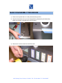
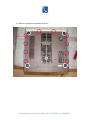
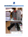
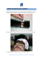
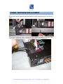
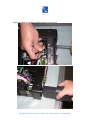
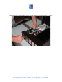
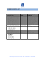
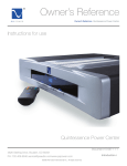
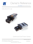
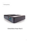
SERVICE MANUAL
Power Plant Premier
APPLICABLE PRODUCTS
Serial numbers PPP-7J and earlier
Document # 11-037-01-1-DSM-A
Released 01/08
4826 Sterling Drive, Boulder, CO 80301 PH: 720.406.8946 FX: 720.406.8967
BASIC DISASSEMBLY PROCEDURE
1) Place the unit upside down on a well protected working surface.
2) Tape the side panels so they are not damaged during disassembly and reassembly.
Make sure the tape is stopped before the back panel
3) Remove the 4 corner screws from the back panel
4826 Sterling Drive, Boulder, CO 80301 PH: 720.406.8946 FX: 720.406.8967
4) Remove 10 screws from the bottom as shown
4826 Sterling Drive, Boulder, CO 80301 PH: 720.406.8946 FX: 720.406.8967
5)
Hold the top and bottom together, and turn the unit over.
6) Slide the top cover forward about 1 inch, then tilt forward.
4826 Sterling Drive, Boulder, CO 80301 PH: 720.406.8946 FX: 720.406.8967
TROUBLESHOOTING
Power Issues
1. Nothing happens when power is applied to the Premier.
a. Check / Replace F1 and F2 on the Power Inlet Assembly.
• Slow Blow 5A 10MM TDA fuses.
b. Replace the Power Cartridge.
2. The circuit breaker in the wall trips when power is applied to the premier.
a. Replace the Power Cartridge.
b. Replace the Power Transformer.
Regulation Issues
1. The Bypass Relay never enables the regulated output.
a. Replace the Regulator PCA and Darlington transistors Q1, Q2, Q3 and Q4.
2. The Bypass Relay ‘clicks’ in and out.
a. Replace the Regulator and Darlington transistors Q1, Q2, Q3 and Q4.
Display Issues
1. The Premier is regulating but there is no Display.
a. Verify there is 8VAC to the Display Board connector J1 (Orange Wires).
b. Replace the Premier Display PCA.
2. Display elements are missing.
a. Replace the Premier Display PCA.
Sequencer / IsoZone Issues
1. Sequencer IsoZone switches are not working.
a. Replace the IsoZone Control Ribbon Cable.
b. Replace the Display PCA.
c. Replace the IsoZone Power Outlet Assembly.
CleanWave
1. CleanWave not Visible
a. Verify that there is 15uf of capacitance on the input.
b. Look for shorts on the back of the Regulator PCA between the pins of J2.
c. Replace the Regulator Control Ribbon Cable.
d. Replace the Display PCA.
e. Replace the Regulator PCA and Darlington transistors Q1, Q2, Q3 and Q4.
MultiWave
1. MultiWave not Visible
a. Look for shorts on the back of the Regulator PCA between the pins of J2.
b. Replace the Regulator Control Ribbon Cable.
c. Replace the Display PCA.
d. Replace the Regulator PCA and Darlington transistors Q1, Q2, Q3 and Q4.
4826 Sterling Drive, Boulder, CO 80301 PH: 720.406.8946 FX: 720.406.8967
Remote Control Issues
1. Remote not Functioning
a. Replace the batteries in the Remote Control.
b. Replace the Remote Control.
c. Replace the Display PCA.
Fan Issues
1. Fans won’t turn.
a. Verify the fans are correctly plugged into the small fan interconnect PCA.
b. Carefully replace Q6 on the Regulator PCA. MFG PN: BC3376G (TO92).
i.
Replace the Q6 Heat Sink using thermal compound.
2. Fans won’t stop after Power Up
a. Check to make sure that all connections to the Main PCA are good.
b. Verify that the correct fan driver transistor Q6 is installed.
For units with one large and one small fan Q6 should be a
i.
BC337G and that it is installed up-side-down compared to the
silk screen on the Main PCA
Repairing the Regulator PCB Assembly (advanced)
1. For qualified technicians who wish to repair the regulator PCB Assembly on the
component level, most situations will require replacing the following components. We
recommend that all of these parts be replaced at once:
a. Q11, Q14 (MMBTA56)
b. Q12, Q13 (MMBTA06)
c. R43, R44 (10 ohms)
d. R39, R40 (47 ohms)
e. D13, D14 (BAV99)
f. R11-R14 (0.12 ohm 5W) (Original boards use 0.05 ohm. When repairing boards,
replace all 4 resistors with 0.12 ohm)
2. All of the above parts are available in a repair kit. (See parts list)
4826 Sterling Drive, Boulder, CO 80301 PH: 720.406.8946 FX: 720.406.8967
HEAT SINK REMOVAL
To remove the Heat-Sink assemblies, remove 4 screws per side.
4826 Sterling Drive, Boulder, CO 80301 PH: 720.406.8946 FX: 720.406.8967
POWER TRANSISTOR REPLACEMENT
To replace the Darlington transistors, remove 4 mounting screws on each heat-sink. The TO3
Insulator Sil-Pads should always be replaced when a transistor is reinstalled for any reason.
After replacement the Darlington transistor mounting screws must be torqued to 8 inch pounds.
If a transistor has failed, be certain to test the emitter resistors R11-R14.
4826 Sterling Drive, Boulder, CO 80301 PH: 720.406.8946 FX: 720.406.8967
REGULATOR PCB REMOVAL
To replace the Main PCA remove the four corner screws being careful to not lose the stand-off
spacers. The thermal sensor R10 is mounted on the bottom side of the PCA so it can protrude
into the heat-sink.This thermal sensor is sometimes glued into the insulating spacer (Better seen
in next picture).
During reassembly, ensure that the thermal sensor is positioned into the insulating spacer.
4826 Sterling Drive, Boulder, CO 80301 PH: 720.406.8946 FX: 720.406.8967
POWER CARTRIDGE REPLACEMENT
Remove the machine screws from above and below the power cartridge using a 5/16th inch hex
driver.
Pry the power cartridge from the in-let assembly using a flat-head screwdriver. The power button
on the power cartridge will catch on the rear bezel after about ½ inch of movement.
4826 Sterling Drive, Boulder, CO 80301 PH: 720.406.8946 FX: 720.406.8967
Depress the button on the power cartridge to allow it to be removed.
4826 Sterling Drive, Boulder, CO 80301 PH: 720.406.8946 FX: 720.406.8967
When replacing the power cartridge, support the in-let assembly to avoid damage to the mounts.
4826 Sterling Drive, Boulder, CO 80301 PH: 720.406.8946 FX: 720.406.8967
FAN DRIVER REPLACEMENT
First check to make sure that all connections to the Main PCA are good.
Next check to make sure that the fan driver transistor Q6 is a BC337G and that it is
installed up-side-down compared to the silk screen on the Main PCA.
Use an Ohm Meter to measure for shorts between the Q6 transistor legs. If a short is
measured, look for a solder bridge between the transistor legs on both sides of the
board. If a short is measured and no solder bridges are found, replace Q6.
4826 Sterling Drive, Boulder, CO 80301 PH: 720.406.8946 FX: 720.406.8967
DISPLAY CALIBRATION
1. With the unit in standby, press the Mode Down, Mode Up and Power Button
(Logo) simultaneously.
2. The 3-digit display should light up. The logo and buttons should not be backlit.
This tells you that you are in calibration mode.
3. The first reading on the display is the incoming voltage. To scroll to other
readings, press the Display button. It will scroll through the readings in the
following order:
1. Input Voltage – Lights On: Input + Volts
2. Output Voltage – Lights On: Diff + Volts
3. Input Distortion – Lights On: Input + Dist %
4. Output Distortion – Lights On: Reduct + Dist %
4. Start with the Input Voltage Calibration.
a. Make sure the Input + Volts Lights Are On.
b. Use the mode up / down buttons to calibrate the reading until the reading
matches the actual input voltage.
5. Now Calibrate The Output Voltage.
a. Press the Display button once.
b. Make sure the Diff + Volts Lights Are On.
c. Use the mode up / down buttons to calibrate the reading until the reading
matches the actual output voltage. (NOTE regenerator is not active during
display calibration)
6. Distortion readings do not normally need calibration, but they can be adjusted the
same way.
7. Press the power button to turn the unit off.
8. Turn unit back on in “normal” mode.
4826 Sterling Drive, Boulder, CO 80301 PH: 720.406.8946 FX: 720.406.8967
COMMON PARTS LIST
Part Description
Slow Blow 5A 5X20mm Fuses
(PS Kit includes 2 fuses)
Power Cartridge
Regulator / Heat Sink Assembly Pair
Regulator PCA
Premier Display PCA
Regulator Control Ribbon Cable
IsoZone Control Ribbon Cable
IsoZone Power Outlet Assembly
Premier Power Transformer
Transistor BC337G (TO92)
(PS Kit includes transistor and heat sink)
Power Transistor Kit
2) MJ11032 Transistor
2) MJ11033 Transistor
4) Insulator Sil-Pads
MJ11032G TO3 Transistor
MJ11033G TO3 Transistor
TO3 Insulator Sil-Pads
Regulator PCB Kit (parts for 5 boards)
10) MMBT06
10) MMBT56
10) BAV99
10) 10 ohm 0805
10) 47 ohm 0805
20) 0.12 ohm 5W
Manufacturer
PS Audio
Littlefuse
PS Audio
PS Audio
PS Audio
PS Audio
PS Audio
PS Audio
PS Audio
PS Audio
PS Audio
On Semiconductor
PS Audio
Part Number
MS-PREM-FUSEKIT-P1
0218005.HXP
PC-CART-US
MS-PREM-REGULATOR-P1
MS-PREM-PCBA-AVR-P1
MS-PREM-PCBA-DISP-P1
MS-PREM-CABLE-AVR-P1
MS-PREM-CABLE-ISOZONE
MS-PREM-ISOZONE
MS-PREM-XFMR-P1
MS-PREM-FAN-TRANSISTOR
BC337G
MS-PREM-TRANSISTORS
On Semiconductor
On Semiconductor
Bergquist
PS Audio
MJ11032G
MJ11033G
SP900S-05
MS-PREM-AVR-KIT
4826 Sterling Drive, Boulder, CO 80301 PH: 720.406.8946 FX: 720.406.8967
ADDITIONAL RESOURCES
Schematics, drawings, manuals, and other product documentation are
available online to PS Audio distributors. The URL is:
http://download.psaudio.com
Contact your sales representative to register.
4826 Sterling Drive, Boulder, CO 80301 PH: 720.406.8946 FX: 720.406.8967