1
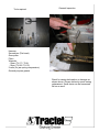
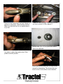
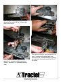
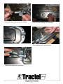
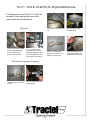
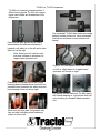
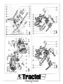
Griphoist-Tirfor
TU-17/TU-8 & TU-28/TU-16
Date: 04/05/04
Version:2a
Service and Maintenence Manual
Table of Contents
UL Listing Card
P. 3
Tools required
P. 4
General Inspection
P. 4
Disassemble TU-17/TU-8
P. 5
Disassemble the two jaw blocks
P. 8
Reassemble
P. 10
Front Jaw Assembly
P. 12
TU-17/TU-8 & TU-28/TU-16 Physical Differences
P. 19
TU-17/TU-8 Dimensions
P. 20
TU-28/TU-16 Dimensions
P. 21
Hydraulic Powered Units
P. 22
TU-28H vs. TU-28 Comparison
P. 23
Appendix A (exploded view for TU-17/TU-8 & TU-28/TU-16)
P. 24
Appendix B (Jaw Inspection)
P. 28
2
UL Listing Card
Northbrook, Ilinois (847) 272- 8800
Melville, New York (631) 271-6200
Santa Clara, California (408) 985-2400
Research Triangle Park,
North Carolina (919) 549-1400
Camas, Washington (360) 817-5500
TRACTEL INC
GRIPHOIST DIV
110 SHAWMUT RD
PO BOX 188
CANTON, MA 02021
TUFV
Equiptment, Scaffolding
April 18, 2002
TRACTEL INC GRIPHOIST DIV
110 SHAWMUT RD PO BOX 188, CANTON MA 02021
SA4785
Electric scaffold hoists, Models ETH-32L, XE301P, maximum load 700 lbs: Models ETH35C, ETH35C3,
ETH35X, LE500P, LE501P, TE401P, -401PA, XE500P, -501P, -501PA, maximum load 1000lbs; Models
TE1000P, -1001P, -1001PA, XE501PO, XE700P, -701P, XE720P, XE721P, maximum load 1500lbs; Models
TE1020P, -1021P, -1021PA, maximum load 2000 lbs; Model XE1020P, maximum load 2400 lbs; Model
XE2050P, maximum load 4400 lbs.
Manually operated scaffold hoists, Model TMS-600, maximum load 1320 lbs; Model TU-17, maximum
load 1500 lbs; Model TU-28, maximum load 3000 lbs; Model TU-32, maximum load 6000 lbs; Model 408, maximum load 880 lbs.
Pneumatic scaffold hoists, Models ATH32L, -32LB, XA300P, -300PB, maximum load 700 lbs; Models
ATH35C ATH35X, -35XB, LA500P, XA500P, -500PB, maximum load 1000 lbs; Models XA700P, -700PB,
XA720PB, maximum load 1500 lbs; Model XA1030PO, maximum load 1850 lbs; Model TA1020P, maximum load
2000 lbs; Model XA1020P, maximum load 2400 lbs; Model XA2050P, maximum load 4400 lbs; Model XA2650P,
maximum load 5300 lbs.
Independent secondary brakes, Model BS15.301, maximum load 1500 lbs; Model BS20.301, maximum
load 3000 lbs; Model BS35.30, maximum load 6000 lbs.
Modular work platform, “Modular Staging”, 2 to 12 m, rated 750 lbs; Models KD01, MP03, 2 to 18m, rated
750 to 1500 lbs; “PFD”, 2 to 15m, load 6000 lbs.
Work Cages, Model PMR0700D, PMR0701D, VSMV-PMR0710D, rated 1000 lbs; Model WC01, rated 400
lbs.
This equipment consists of separate parts inspected at the factory by Underwriters Laboratories Inc. and is
intended for use in complete complete installations. Installations are not inspected by Underwriters Laboratories
Inc. but should be made in accordance with requirements of authorities having jurisdiction.
LOOK FOR CLASSIFICATION MARK ON PRODUCT
3
General Inspection
Tools required
Hammer
Screwdriver (Flat head)
Gear puller
Pliers
Wrenchs
-10mm (TU-17 / TU-8)
-13mm (TU-28 / TU-16)
2 nails (for jaw spring compression)
General purpose grease
Check for casing deformation or damage as
shown above. Severe deformity needs casing
replacement. Small dents can be hammered
flat on an anvil.
4
Disassemble TU-17 / TU-8
Use a gear puller to remove power stroke
lever and shear pins.
Remove the handle and aluminum shear
pins. (2 shear pins for TU-17, 3 shear pins
from TU-28) If shear pins are broken, hoist
has been overloaded. If shear pins have
been replaced by steel fasteners, screws or
welded the crankshaft / power stroke lever
assembly must be replaced.
Place Tirfor on vice for easier removal of
casing screws.
2 sets of spare shear pins are found in the
power stroke lever under a plastic cap. If
missing replace them.
Check that mushroom capped rivet is in
place. It holds the telescopic handle in
place.
5
Remove casing screws.
10mm wrench TU-17 / TU-8
Check for wear or any loose parts (snap
rings) inside casing cover.
Check that both casing bushings are in
place and in good condition. No splits,
etc.
Remove casing cover once casing
screws are removed.
6
Check for roller damage. If axle has punched
out hole in center of roller replace it.
Check for bent safety latch on hook. Repair or
replace as necessary. check latching function.
Make sure that the hook is not opened due to
a tip load.
Broken roller (TU-17/TU-8) as shown above
need to be replaced.
Use pliers to adjust bent safety latch. Side
plates should be parallel.
Check that clutch pusher has not been mushroomed by hammering. This shows that user
tried to move it with anchor hook extended.
7
Disassemble the two jaw blocks
Remove pin snap from reversing lever pin
(Position. 39) and remove reversing lever
connecting rod from assembly.
Remove pin snap ring (5 mm) from upper pin
of reversing lever (Position. 040) and clutch
pin (Position. 041)
Push pins through reversing lever and dissassemble reversing lever connecting rod
Remove pin snap from crankshaft connecting
rod (Position. 919) and remove crankshaft
power stroke lever. Check that nylon bushings
are in place and not broken.
8
Warning: Never remove jaw pins until springs has been compressed and nail is
placed through hole in shaft to prevent it from flying upon disassembly.
Compress the springs and place a nail in jaw
spring shaft before removing spring from jaw
assembly.
Inspect jaw wear and replace when nessasary. (see appendix B for jaw inspection)
Dissassemble front jaw the same way.
Thoroughly clean and inspect all parts before
reassemble. New grease must be applied for
reassembly.
Warning! Do not use any grease with
graphite or molydisulphide. These
can cause slippage between the wire
rope and jaws.
Remove pin snap ring from pin (Position. 032
& Position. 034) and dissassemble jaw assembly
9
Reassemble
Assemble jaw as shown above. (Refer to
exploded view in appendix A for assembly)
Generously grease each part and start
assembly by laying down jaw actuating cam
and free cam (Position. 14 & Position. 15)
Note: Make sure to apply extreme pressure grease to the jaw keys. Lack of lubrication on
the S shaped jaw keys can cause the jaws to stick and “pumping occurs where the rope
does not advance through the machine when operating.
10
Slide rear jaw connecting plate over the jaw
assembly. Be careful that the S shaped jaw
keys do not fall out.
Place spring in position, apply pressure to aw
cam to compress the spring slightly and
remove the nail. Finalize assembly by placing
pin snap back on pin and center the axle for
the rollers.
Place 4 flat washers and 1 spacer in to
assembly for complete rear jaw assembly.
(Refer to appendix A for exploded assembly
view)
11
Front jaw assembly
Grease nylon roller and place roller with
washers on to jaw assembly pin. (Position.
034)
Generously grease each part and assemble
jaw the same way as rear jaw.
Place crankshaft on to rear jaw connecting
plates. Make sure that the stop pin is
recessed in the side plate slot.
12
Place bushing between free cams. Place
jaw assembly into front jaw assembly plate.
Place 4 flat washer and pin in alignment.
Once assembly finalized, remove nail and
secure pin in assembly by pin snap ring.
13
Grease roller and place roller on jaw assembly pin on guide roller. (Position. 034)
Secure crankshaft connecting pin with pin
snap ring.
Connect front and rear jaw with crankshaft.
(Position. 919)
Start reversing lever assembly by fasten lever
in place with reversing lever pin (Position.
039)
14
Place spacer and fasten reversing lever connecting rods with reversing lever pin.
(Position. 039)
Assemble clutch actuating lever sub assembely to reversing lever. Secure assembly with pin
and pin snap ring.
Assemble reversing connecting rods
(Position.021) to Reversing lever (Position.
903)
15
Grease right hand casing and check for casing deformity, nylon bushing, and bearing
wear.
Make sure casing spacer thread (Position.
045) is fastened before placing the jaws into
cover.
Place jaws into casing and tuck the spring on
clutch actuating lever in to casing. Use a vise
grip to hold clutch actuating lever in place.
16
Assemble clutch lock pusher into casing.
Place left hand casing over assembly.
Place rope entry in position.
Start tightening all casing screws.
Place anchoring hook in position.
17
Fasten through casing screw.
Place hoist on vise for easier assembly.
Grease shaft and install power stroke lever
on crankshaft. Secure it with 2 new shear
pins for TU-17/TU-8 and 3 for TU-28/TU-18.
Do not reuse shear pins.
Make sure casing flange is in place for fastening
18
TU-17 / TU-8 & TU-28/TU-16 Physical Differences
TU-28 appears to look like the TU-17 with the
exception in size and several minor differences which are described below.
The Hook
TU-28 shown above has
a loose casing strengthener to reinforce the
area around the hook.
TU-17 shown above
does not have a loose
casing strengthener, but
has reinforcement in the
hook area of the casing.
The clutch lock pusher with spring
TU-28’s clutch lock pusher with.
TU-17’s clutch lock pusher with spring.
19
TU-28 has a carrying handle.
TU-17 does not have
carrying handl.
TU-28’s crankshaft w/
power stroke lever has 3
aluminum shear pins.
TU-17’s crankshaft w/
power stroke lever has
2 aluminum shear pins.
TU-17 Dimensions
Telescopic Control Lever
20
TU-28 Dimensions
Telescope Control Lever
21
Hydraulic Powered Units
The hydraulic powered Tirfors are
special mahcines that is powered by
a self reciprocating hydraulic cylinder.
Since fatique of the operator is not a
factor, these machines are typically
used for heavy loads over a longer
distance. For extra durability and
more severe service, the hydraulic
machines have bearings in place of
bushings and heat treated components.
22
TU-28H vs. TU-28 Comparison
TU-28H is a hydraulic powered device. It
differs from a regular TU-28 in the components used. Below are illustrations of the
differences.
Top crankshaft TU-28H has reinforced needle
bearing contact surface vs. lower crankshaft
that has no reinforced contact surface with
casing.
Power stroke lever shown above clearly
demonstrates the difference between a
hydraulic unit which is on the left and a standard unit on the right.
Note: Shear pins for hydrolic units
are steel compare to aluminum for
regular hand operated unit.
Hydrolic unit has tapered hook base shown
on left vs. ridgid base on a regular hand
operated unit shown on right.
Crankshaft for hydraulic units has needle
bearings demonstrated above on the left vs.
standard hand operated unit which does not
have bearing shown on above right.
Left picture shows reinforced TU-28H casing
with needle bearing vs. right picture that has
nylon bushing for standard hand operated
unit.
Both front and rear jaws for hydraulic unit
has red paint indicating extra hardening
shown on above left.
23
Exploded view for TU-17
Appendix A
24
25
TU-28 exploded view
26
27
Appendix B
Jaw inspection
The Wear on the jaws of the tirfor hoists is generally very small. It is nevertheless recommended
to check periodically the wear when inspecting and repairing the machines. This checking can
be made on mounted jaws.
1) Introduce the measuring rod (see table for diameter according to model) between both jaws;
2) Place a square under jaw assembly pins:
a) if the hole of reversing lever pin is still partially covered by the square, the jaws are OK;
b) if this hole is completely uncovered, the jaws are worn and must be replaced. In this
case, better check also the other wear parts mentioned in the list hereunder and
eventually replace them at the same time.
28