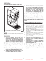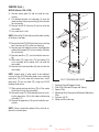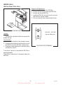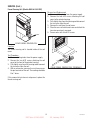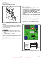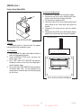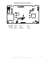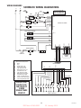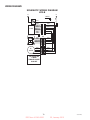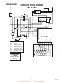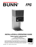
1
RELEASED FOR PRODUCTION
GRINDERS
Includes: MHG, FPG,
FPG-2, LPG-2, G1, G2, G3,
G2 trifecta™, G9, G9WD,
G9-2 & G9-2T DBC
SERVICE & REPAIR MANUAL
BUNN-O-MATIC CORPORATION
POST OFFICE BOX 3227
SPRINGFIELD, ILLINOIS 62708-3227
PHONE: (217) 529-6601 FAX: (217) 529-6644
To ensure you have the latest revision of the Operating Manual, or to view the Illustrated Parts
Catalog, Programming Manual, or Service Manual, please visit the Bunn-O-Matic website, at
www.bunn.com. This is absolutely FREE, and the quickest way to obtain the latest catalog and
manual updates. For Technical Service, contact Bunn-O-Matic Corporation at 1-800-286-6070.
41545.0000E
11/14 ©2009 Bunn-O-Matic Corporation
DIR Num: 41545.0000
20, January 2015
RELEASED FOR PRODUCTION
BUNN-O-MATIC COMMERCIAL PRODUCT WARRANTY
Bunn-O-Matic Corp. (“BUNN”) warrants equipment manufactured by it as follows:
1) Airpots, thermal carafes, decanters, GPR servers, iced tea/coffee dispensers, MCR/MCP/MCA single cup brewers, thermal servers and ThermoFresh® servers (mechanical and digital) 1 year parts and 1 year labor.
2) All other equipment - 2 years parts and 1 year labor plus added warranties as specified below:
a) Electronic circuit and/or control boards - parts and labor for 3 years.
b) Compressors on refrigeration equipment - 5 years parts and 1 year labor.
c) Grinding burrs on coffee grinding equipment to grind coffee to meet original factory screen sieve analysis - parts and
labor for 4 years or 40,000 pounds of coffee, whichever comes first.
These warranty periods run from the date of installation BUNN warrants that the equipment manufactured by it will be
commercially free of defects in material and workmanship existing at the time of manufacture and appearing within the
applicable warranty period. This warranty does not apply to any equipment, component or part that was not manufactured
by BUNN or that, in BUNN’s judgment, has been affected by misuse, neglect, alteration, improper installation or operation,
improper maintenance or repair, non periodic cleaning and descaling, equipment failures related to poor water quality,
damage or casualty. In addition, the warranty does not apply to replacement of items subject to normal use including but
not limited to user replaceable parts such as seals and gaskets. This warranty is conditioned on the Buyer 1) giving BUNN
prompt notice of any claim to be made under this warranty by telephone at (217) 529-6601 or by writing to Post Office Box
3227, Springfield, Illinois 62708-3227; 2) if requested by BUNN, shipping the defective equipment prepaid to an authorized
BUNN service location; and 3) receiving prior authorization from BUNN that the defective equipment is under warranty.
THE FOREGOING WARRANTY IS EXCLUSIVE AND IS IN LIEU OF ANY OTHER WARRANTY, WRITTEN OR ORAL, EXPRESS OR IMPLIED, INCLUDING, BUT NOT LIMITED TO, ANY IMPLIED WARRANTY OF EITHER MERCHANTABILITY
OR FITNESS FOR A PARTICULAR PURPOSE. The agents, dealers or employees of BUNN are not authorized to make
modifications to this warranty or to make additional warranties that are binding on BUNN. Accordingly, statements by such
individuals, whether oral or written, do not constitute warranties and should not be relied upon.
If BUNN determines in its sole discretion that the equipment does not conform to the warranty, BUNN, at its exclusive option while the equipment is under warranty, shall either 1) provide at no charge replacement parts and/or labor (during the
applicable parts and labor warranty periods specified above) to repair the defective components, provided that this repair
is done by a BUNN Authorized Service Representative; or 2) shall replace the equipment or refund the purchase price for
the equipment.
THE BUYER’S REMEDY AGAINST BUNN FOR THE BREACH OF ANY OBLIGATION ARISING OUT OF THE SALE OF THIS
EQUIPMENT, WHETHER DERIVED FROM WARRANTY OR OTHERWISE, SHALL BE LIMITED, AT BUNN’S SOLE OPTION
AS SPECIFIED HEREIN, TO REPAIR, REPLACEMENT OR REFUND.
In no event shall BUNN be liable for any other damage or loss, including, but not limited to, lost profits, lost sales, loss of
use of equipment, claims of Buyer’s customers, cost of capital, cost of down time, cost of substitute equipment, facilities
or services, or any other special, incidental or consequential damages.
392, A Partner You Can Count On, Air Infusion, AutoPOD, AXIOM, BrewLOGIC, BrewMETER, Brew Better Not Bitter, BrewWISE, BrewWIZARD, BUNN Espress, BUNN Family Gourmet, BUNN Gourmet, BUNN Pour-O-Matic, BUNN, BUNN with
the stylized red line, BUNNlink, Bunn-OMatic, Bunn-O-Matic, BUNNserve, BUNNSERVE with the stylized wrench design,
Cool Froth, DBC, Dr. Brew stylized Dr. design, Dual, Easy Pour, EasyClear, EasyGard, FlavorGard, Gourmet Ice, Gourmet
Juice, High Intensity, iMIX, Infusion Series, Intellisteam, My Café, Phase Brew, PowerLogic, Quality Beverage Equipment
Worldwide, Respect Earth, Respect Earth with the stylized leaf and coffee cherry design, Safety-Fresh, savemycoffee.com,
Scale-Pro, Silver Series, Single, Smart Funnel, Smart Hopper, SmartWAVE, Soft Heat, SplashGard, The Mark of Quality in
Beverage Equipment Worldwide, ThermoFresh, Titan, trifecta, TRIFECTA (sylized logo), Velocity Brew, Air Brew, Beverage
Bar Creator, Beverage Profit Calculator, Brew better, not bitter., Build-A-Drink, BUNNSource, Coffee At Its Best, Cyclonic
Heating System, Daypart, Digital Brewer Control, Element, Milk Texturing Fusion, Nothing Brews Like a BUNN, Picture
Prompted Cleaning, Pouring Profits, Signature Series, Sure Tamp, Tea At Its Best, The Horizontal Red Line, Ultra are either
trademarks or registered trademarks of Bunn-O-Matic Corporation. The commercial trifecta® brewer housing configuration is a trademark of Bunn-O-Matic Corporation.
2
DIR Num: 41545.0000
41545 031314
20, January 2015
RELEASED FOR PRODUCTION
CONTENTS
Warranty and Trademark..................................................................................................3
Introduction.....................................................................................................................4
Recommended Daily Cleaning.........................................................................................4
G9WD Packaging & Shim Removal.................................................................................5
Operating Controls...........................................................................................................6
Troubleshooting.............................................................................................................10
Service..........................................................................................................................14
Component Access............................................................................................14
Bag Sensor........................................................................................................15
Motor and Grind Chamber.................................................................................16
Capacitor............................................................................................................30
Circuit Breaker...................................................................................................31
Hopper Selector Switch.....................................................................................32
Off/On/Start Switch............................................................................................34
Urn/Carafe Selector Switch................................................................................35
Batch Selector Switch........................................................................................36
Potentiometer....................................................................................................37
Rectifier.............................................................................................................38
Relay..................................................................................................................39
Hopper Slide Plates............................................................................................43
Solenoid.............................................................................................................45
Timer.................................................................................................................46
Control Board.....................................................................................................50
Membrane Switch..............................................................................................52
EMI Filter............................................................................................................54
Funnel Sensing Coil...........................................................................................55
Memory Clock Board.........................................................................................56
Display Board.....................................................................................................57
Wiring Schematics.........................................................................................................58
3
DIR Num: 41545.0000
41545 111711
20, January 2015
RELEASED FOR PRODUCTION
INTRODUCTION
The Grinder will store various amounts of whole bean coffee and grind it to a preset grind and amount into
an awaiting funnel and filter or French Press from most commercial drip coffee brewers. The equipment is only
for indoor use on a sturdy counter or shelf. Adequate space must be available above the grinder to raise the lid
when adding beans. Use only with whole bean coffee.
The grind is preset at the factory to drip specifications as set forth by the United States Department of Commerce and adopted by the Coffee Brewing Center of the Pan American Coffee Bureau. Adjustments may be made
to alter both the amount and grind from the factory setting. Refer to the Installation & Operating Manuals for
ADJUSTMENTS.
RECOMMENDED DAILY CLEANING
The use of a damp cloth rinsed in any mild, nonabrasive, liquid detergent is recommended for cleaning all
surfaces on Bunn-O-Matic equipment. Care should be taken not to scratch the hopper or windows with any
abrasive material. Regular cleaning will keep your grinder looking new for years. Refer to the Installation &
Operating Manuals for CLEANING.
CAPACITY CHART
FPG, LPG.................................Six pounds
FPG-2.......................................Three pounds in each hopper
MHG.........................................Five pounds in each hopper
G9............................................Nine pounds
G9-2, G9-2T DBC.....................Six pounds in each hopper
G9WD......................................Five pounds
G1............................................One pound
G2............................................Two pounds
G3............................................Three pounds
G2 trifecta................................Two pounds
4
DIR Num: 41545.0000
41545 072710
20, January 2015
RELEASED FOR PRODUCTION
G9 WD - Packaging & Shim Removal
WARNING
MUST BE COMPLETED BY AUTHORIZED SERVICE PERSONNEL.
DO NOT PLUG IN !
SEE INSTRUCTIONS BELOW BEFORE USING !
Step 1 - Remove & discard tape holding funnel arm in place. (Figure 1)
Step 2 - Remove & discard two silicon tubes between funnel guide &
housing. (Figure 2)
Step 3 - Remove four screws in front housing panel. (Figure 3)
Step 4 - Remove & discard shim under transducer. (Figure 4)
Step 5 - Replace housing panel and secure four screws. (Figure 3)
Figure 1
Figure 2
Figure 3
Figure 4
5
DIR Num: 41545.0000
41545 111711
20, January 2015
RELEASED FOR PRODUCTION
OPERATING CONTROLS
Model G9WD
d
Grind Pad (a)
Pressing initiates a grind cycle.
Stop Pad (b)
Pressing ends the operation of the grinder.
e
® Pad (c)
Pressing the copyright pad allows programming access.
a
Pads (d)
“Hidden” buttons used to navigate setup and programming menus.
Pads (e)
Press button to select small, medium or large batch size.
c
b
Model G9-2
Off/On/Start Switch
OFF - (upper position) Switching to this position stops all operation of the grinder.
ON - (middle position) The switch will return to this position after a grind cycle has begun and will remain
in this position after grinding has ceased.
START - (lower, momentary position) Pressing the switch initiates a timed grind cycle.
Hopper Selector Switch
Left - Switching to this position allows beans to be dispensed from the
left hopper.
Right - Switching to this position allows beans to be dispensed from the
right hopper.
Batch Selector Switch (Optional)
Urn - Switching to this position allows the correct amount of beans to be
dispensed when grinding a large batch.
CARAFE - Switching to this position allows the correct amount of beans
to be dispensed when grinding a small batch.
P633
Dispense Timer
The dispense timer controls the amount of beans that will leave the hopper in a grind cycle. The timer can
be adjusted to dispense a different amount from each hopper. The scale is from 0.4 to 150.0 seconds. Refer to
the Installation & Operating Manuals for Adjustments.
6
DIR Num: 41545.0000
41545 111711
20, January 2015
RELEASED FOR PRODUCTION
OPERATING CONTROLS (Continued)
Model G9
Off/On/Start Switch
OFF - (left position)
Placing the switch in this position stops the operation of the grinder.
ON - (center, resting position)
The switch will return to this position after a grind cycle has begun and will remain in this
position after grinding has ceased.
START - (right, momentary position)
Placing the switch in this position initiates a timed grind cycle.
URN
ON
O
F
F
S
T
A
R
T
CARAFE
P1300
Batch Selector Switch (Optional)
URN - Switching to this position allows the correct amount of beans to be dispensed when grinding a large batch.
CARAFE - Switching to this position allows the correct amount of beans to be dispensed when grinding a small
batch.
Models G1, G2, G3 & G2 trifecta
Off/On/Start Switch
OFF - (upper position)
Switching to this position stops the operation of the grinder.
ON - (center, resting position)
The switch will return to this position after a grind cycle has begun and will remain in this position after grinding has ceased.
START - (lower, momentary position)
Pressing the switch initiates grinding only when a bag is in place behind the chute.
Grind Selector
Allows the user to vary the grind for each bag of coffee. Each setting will provide precisely the same grind every time it is
selected.
Bag Sensor
Prevents the grinder from operating unless the back of a bag is in place behind the dispense chute.
Do not attempt to bypass this safety device.
Models LPG, LPG-2E
Off/On/Start Switch (Models LPG and LPG-2E)
OFF - (upper position) Switching to this position stops all operation of the grinder.
ON - (middle position) The switch will return to this position after a grind cycle has begun
and will remain in this position after grinding has ceased.
START - (lower, momentary position) Pressing the switch to this position and releasing initiates a grind cycle.
P1028
Hopper Selector Switch (Model LPG-2E only)
LEFT - Switching to this position allows beans to be ground from the left hopper.
RIGHT - Switching to this position allows beans to be ground from the right hopper.
P1029
7
DIR Num: 41545.0000
41545 111711
20, January 2015
RELEASED FOR PRODUCTION
OPERATING CONTROLS (Continued)
c
Model MHG
Grind Pad (a)
Pressing initiates a timed grind cycle.
Stop Pad (b)
Pressing ends the operation of the grinder.
® PAD (c)
Pressing the ® pad allows programming access.
d
d
a
b
Hopper/Batch Selector Pads (d)
These pads are located on the funnel depictions on each side of the grinder with a total of 6 pads. Selecting one
of these pads will select the amount of grind and side from which to grind.
Example: Selecting the lower pad on the left side will grind enough beans from the left hopper of the grinder to
brew the amount programmed into grinder.
PANTONE
Red 032 CV
PANTONE
430 CVC
PANTONE
432 CVC
PANTONE
354 CVC
PANTONE
Black C
Control Board
The control board determines the amount of beans that will leave the hopper in a grind cycle. The timer portion
can be adjusted to dispense a different amount from each hopper and each batch size. The scale is from 0.4 to
99.9 seconds. Refer to the Installation & Operating Manuals for Adjustments.
c
Model G9-2T DBC
Grind Pad (a)
d
Pressing initiates a timed grind cycle.
Stop Pad (b)
Pressing ends the operation of the grinder.
a
® PAD (c)
Pressing the ® pad allows programming access.
d
b
e
Hopper/Batch Selector Pads (d)
These pads are located on the funnel depictions on each side of the grinder with a total of 6 pads. Selecting one
of these pads will select the amount of grind and side from which to grind.
Example: Selecting the lower pad on the left side will grind enough beans from the left hopper of the grinder to
brew the amount programmed into grinder.
Power ON/OFF Pad (e) (100V Models)
Pressing the ON/OFF pad alternately turns the grinder on and off.
Control Board
The control board determines the amount of beans that will leave the hopper in a grind cycle. The timer portion
can be adjusted to dispense a different amount from each hopper and each batch size. The scale is from 0.4 to
99.9 seconds. Refer to the Installation & Operating Manuals for Adjustments.
8
DIR Num: 41545.0000
41545 122209
20, January 2015
RELEASED FOR PRODUCTION
OPERATING CONTROLS (Continued)
Model FPG
Off/On/Start Switch
OFF - (upper position) Switching to this position stops all operation of
the grinder.
ON - (middle position) The switch will return to this position after a grind
cycle has begun and will remain in this position after grinding has ceased.
START - (lower, momentary position) Pressing the switch to this position
and releasing initiates a grind cycle.
P2947
Batch Selector Switch
Select Small, Medium or Large batch by turning the round selector knob
on the left front of the grinder.
P2947
Model FPG-2 DBC
c
Grind Pad (a)
Pressing GRIND initiates a timed grind cycle.
Stop Pad (b)
Pressing STOP ends the operation of the grinder.
® PAD (c)
Pressing the ® pad allows programming access
(see page 5).
d
d
a
b
Hopper/Batch Selector Pads (d)
These pads are located on the funnel depictions on each side of the grinder with a total of 6 pads. Selecting
one of these pads will select the amount of grind and side from which to grind.
Example: Selecting the lower pad on the left side will grind enough beans from the left side of the grinder
to brew the amount programmed into grinder.
Control Board
The control board determines the amount of beans that will leave the hopper in a grind cycle. The timer portion can be adjusted to dispense a different amount from each hopper and each batch size. The scale is from 0.4
to 99.9 seconds. Refer to the Installation & Operating Manuals for Adjustments.
9
DIR Num: 41545.0000
41545 122209
20, January 2015
RELEASED FOR PRODUCTION
TROUBLESHOOTING
A troubleshooting guide is provided to suggest probable causes and remedies for the most likely problems
encountered. If the problem remains after exhausting the troubleshooting steps, contact the Bunn-O-Matic
Technical Service Department.
• Inspection, testing, and repair of electrical equipment should be performed only by qualified service
personnel.
• All electronic components have ac voltage and dc voltage potential on their terminals. Shorting of terminals or the application of external voltages may result in board failure.
• Intermittent operation of electronic circuit boards is unlikely. Board failure will normally be permanent.
If an intermittent condition is encountered, the cause will likely be a switch contact or a loose connection
at a terminal or crimp.
• Make certain that all electrical connections are tight and isolated.
WARNING
• Exercise extreme caution when servicing electrical equipment.
• Turn power OFF when servicing, except when electrical tests are specified.
• Follow recommended service procedures.
• Replace all protective shields or safety notices.
Problem
Probable Cause
Remedy
Grinder will not start.
1. No power or incorrect voltage
(A) Plug-in the grinder.
(B) Check the voltage at the wall
outlet with a voltmeter. It must be
120 volts ac for 120 volt models,
100 volts for 100 volt models, and
230 volts for 230 volt models.
2. Off/On/Start switch
(A) Momentarily press the Off/On/
Start switch to the “START” position.
(B) Refer to Service - Off/On/Start
switch for testing procedures.
3. Circuit Breaker (Not applicable on Press the “Reset” button, located on
Model LPG with capacitor)
rear of the grinder. Listen carefully
for a “click”. This resets the motor
protection circuit and indicates that
an overload may have been encountered by the motor. (An overload can
occur when something other than
coffee is inserted into the hopper for
grinding). Refer to Service - Circuit
Breaker for testing procedure.
Refer to Service - Timer for testing
procedures.
4. Timer
10
DIR Num: 41545.0000
41545 122209
20, January 2015
RELEASED FOR PRODUCTION
TROUBLESHOOTING (cont.)
Problem
Probable Cause
Remedy
Grinder will not start. (Continued)
5. Motor
Each motor is equipped with a
temperature and current overload
protection feature which will immediately shut off the motor when
an overload has occurred. Check
the grinder for obstructions. Refer
to Service - Motor for testing procedures.
6. Relay
Refer to Service - Relay for testing
procedures.
7. Bag sensor or Cup Sensor
(A) The receiving bag must be placed
on the tray screen and have the back
of the bag behind the dispense chute
to activate the sensor switch.
(B) Refer to Service - Bag Sensor
Switch for testing and adjustment
procedures.
Grinder will not shut off.
(A) Place the switch in the “OFF”
upper position.
1. Off/On/Start switch
(B) Refer to Service - Off/On/Start
Switch for testing procedures.
2. Timer
Refer to Service - Timer for testing
procedures.
3. Relay
4. Bag Sensor or Cup Sensor
Refer to Service - Relay for testing
procedures.
(A) Remove bag from under the
dispense chute.
(B) Refer to Service - Bag Sensor
Switch for testing procedures.
11
DIR Num: 41545.0000
41545 072710
20, January 2015
RELEASED FOR PRODUCTION
Problem
Probable Cause
Remedy
Grinder starts, but will not dispense
from hopper.
1. Hopper(s)
Begin each grind cycle by visually
inspecting the hopper(s) for ample
supplies of whole bean coffee.
2. Blockage of hopper(s)
Foreign materials must not block
the openings at the bottom of the
hopper(s).
3. Slide Gate Solenoids (Model LPG2E only)
Refer to Service - Solenoids for testing procedures.
4. Timer
Refer to Service - Timer for testing
procedures.
5. Off/On/Start switch
Refer to Service - Off/On/Start
switch for testing procedures.
6. Slide plates
(A) Check to see that the slide plates
move freely to allow beans to travel
into the grind chamber.
(B) Refer to Service -Slide Plates for
testing procedures.
Incorrect amount of coffee.
7. Solenoids
Refer to Service - Solenoids for testing procedures.
8. Solenoid Limit Thermostat
Refer to Service - Solenoids for testing procedures.
9. Shear Plate
Remove both black fillister head
screws holding the grinder selector
dial plate to the grinder. Carefully
remove the dial plate and rotor cup.
Inspect the shear plate for wear.
Replace if excessively worn or damaged.
1. Timer adjustment
Refer to the Adjustment section
in the Installation and Operation
Manual.
2. Snubber
Refer to Service - Snubber for replacement procedures.
12
DIR Num: 41545.0000
41545 122209
20, January 2015
RELEASED FOR PRODUCTION
TROUBLESHOOTING (cont.)
PROBLEM
Incorrect coffee grind dispensed.
PROBABLE CAUSE
1. Burr adjustment
REMEDY
Refer to the Adjustment section
in the Installation and Operation
Manual.
Excessive chaff
1. Dechaffer
Replace the dechaffer springs.
Replacement dechaffer springs are
provided in the literature package
accompnting the grinder.
Grinder only dispenses from one
hopper
1. Hopper selector switch (Model
LPG-2E only)
Refer to Service - Hopper selector
switch for testing procedures.
Timer will not display or displays
incorrectly.
1. Digital Timer
(A) Unplug the grinder. Wait a few
seconds and plug it in again.
(B) Refer to Service - Timer for testing procedures.
Incorrect weight of coffee dispensed
1.Grinder scale requires calibration.
Refer to GRINDER SCALE CALIBRATION procedure.
2. Funnel handle touched during
grinding.
Do not touch funnel or funnel handle during grinding operation.
13
DIR Num: 41545.0000
41545 072710
20, January 2015
RELEASED FOR PRODUCTION
SERVICE
This section provides procedures for testing and
replacing various major components used in this
grinder should service become necessary. Refer to
Troubleshooting for assistance in determining the
cause of any problem.
WARNING - Inspection, testing, and repair of electrical equipment should be performed only by qualified
service personnel. The grinder should be unplugged
when servicing, except when electrical tests are required and the test procedure specifically states to
plug-in the grinder.
P1306
Component Access
WARNING - Unplug the grinder before the removal of
any panel or the replacement of any component.
All components are accessible by the removal of the
lid, hopper, or front and rear access panels. Mark and
retain all screws,washers and nuts for installation.
Component Locations
Some pictures showing component locations may be
general to all grinders unless the component is specific
to your model.
P1307
P602
P1308
CAUTION
PERSONAL INJURY
HAZARD.
KEEP FINGERS AND
FOREIGN OBJECTS
OUT OF HOPPER
OR CHUTE OPENING.
P603
14
DIR Num: 41545.0000
41545 122209
20, January 2015
RELEASED FOR PRODUCTION
SERVICE (Cont.)
BAG SENSOR SWITCH (Models G1, G2, G3) or
CUP SENSOR SWITCH (MODEL G2 TRIFECTA)
4. Disconnect the grinder from the power source.
If voltage is present as described, proceed to
#5.
If voltage is not present as described, refer to the
Wiring Diagrams and check the grinder wiring
harness.
5. Check for continuity across the terminals on the
bag sensor switch.
If continuity is present as described, reconnect the
wires, the switch is operating properly.
If continuity is not present as described, replace the
switch.
Removal and Replacement:
1. Remove the wires from the switch.
2. Remove the two #8-32 keps nuts securing the bag
sensor assembly to the grinder housing.
3. Remove the two #2-56 screws, nuts and external
tooth lockwashers securing the switch to the bag
sensor assembly.
4. Mount the new switch to the bag sensor assembly
using two #2-56 screws, nuts and external tooth
lockwashers. Adjust the assembly by locating the
corner of the switch housing to the top edge of
the black metal mounting bracket.
5. Reattach the sensor assembly to the grinder housing and secure with two #8-32 keps nuts.
6. Refer to Fig. 2 when reconnecting the wires.
P1704
FIG. 1 BAG SENSOR SWITCH
Location:
The bag sensor switch is located inside the lower
front of the grinder housing behind the coffee dispensing chute.
Test Procedure:
1. Disconnect the grinder and place a coffee bag
behind the dispense chute.
2. Remove the white/violet wire from the bag sensor
switch.
3. Check the voltage across the white/violet wire
from the bag sensor switch and the white wire,
red/black wire or red wire on the relay coil with
a voltmeter. Hold the Off/On/Start switch in the
“START” (lower) position and connect the grinder
to the power source. The indication must be:
a. 120 volts ac for two wire 120 volt models.
b. 230 volts ac for two wire 230 volt models.
c. 240 volts ac for two wire 240 volt models.
WHI/VIO from
Off/On/Start
Switch
WHI/ORA to
Terminal “A”
on Relay
FIG. 2 BAG SENSOR SWITCH TERMINALS
15
DIR Num: 41545.0000
P1705
41545 072710
20, January 2015
RELEASED FOR PRODUCTION
SERVICE (Cont.)
4. Check the voltage across the white, red or red/
black and white/blue wires on terminals L1 & L2
with a voltmeter. Connect the grinder to the power
source. When the Off/On/Start switch is momentarily placed in the “START” (lower) position and
then left in the “ON” (center) position and a bag
is in place behind the coffee dispense chute.
The indication must be:
a. 120 volts ac for two wire 120 volt models.
b. 230 volts ac for two wire 230 volt models
c. 240 volts ac for two wire 240 volt models.
5. Disconnect the grinder from the power source.
AC MOTOR AND GRIND CHAMBER
If voltage is present as described replace the motor.
If voltage is not present as described, reconnect the
white, red or red/black and white/blue wires to the motor, refer to the Wiring Diagrams and check the grinder
wiring harness.
Removal and Replacement - Motor (Refer to FIG.6):
1. Remove the plate on the rear of the motor and
disconnect all wires from the motor.
2. Remove the two .250”-20 screws (1) securing
grind selector dial plate and grind selector knob
(2) to the grind chamber. Remove dial plate and
selector knob as an assembly.
3. Slide burr (7), auger rotor/spring assembly (3),
shear plate (4) and burr rotor cup (5) off the
grinder motor shaft as an assembly.
4. Remove the two .250”-20 screws (8) securing the
stationary burr (9) to the grind chamber.
5. Remove bushing (10) and shaft extension (11)
from the grinder motor shaft.
6. Remove the two #8 thread forming screws (12)
securing the fill plate (13) to grinder housing and
remove plate (13).
7. Remove the four #10-24 screws (14) securing the
chute assembly (15) to the grind chamber and
remove chute assembly (15).
8. Remove the four .250”-20 screws, flat washer and
rubber washers securing the motor to the mounting bracket.
9. Remove motor out the rear of the grinder housing.
10. Remove the four .250”-20 cage nuts from the
motor mount.
P1704
FIG. 3 AC MOTOR AND GRIND CHAMBER
Location:
The motor is located inside the upper part of the
grinder housing.
Test Procedure:
1. Remove the plug located on the right side of the
housing. Press the red “Reset” button visible
through the opening. Listen carefully for a “click”.
This resets the motor protection circuit and may
indicate that something other than coffee was
inserted into the hopper for grinding.
If the grinder remains unable to start, proceed to #2.
If the grinder stops operating shortly after starting, refer
to removal and replacement instructions and inspect
for foreign materials.
2. Disconnect the grinder from the power source and
place a coffee bag behind the dispense chute.
3. Remove the electrical access panel at the rear of
the motor.
16
DIR Num: 41545.0000
41545 122209
20, January 2015
RELEASED FOR PRODUCTION
SERVICE (Cont.)
AC MOTOR AND GRIND CHAMBER (cont.)
19. Install burr rotor cup (5).
20. Install grind selector dial plate and grind selector
knob assembly on the grind chamber housing and
secure with two .250”-20 screws.
21. Refer to Fig. 4 and reconnect the wires.
22. Refer to ADJUSTMENTS in the Installation and
Operating Manual, and reset the burrs.
11. Clean all grinding burrs and mounting surfaces
before reassembly.
12. Install the four .250”-20 cage nuts on the new
motor.
13. Place the new motor with hopper collar and bushing into position on the bushings on the motor
mounting bracket.
14. Using four .250”-20 screws, flat washers and
rubber washers secure the motor to the mounting
bracket.
15. Install stationary burr (9) to the grind chamber
housing using two .250”-20 screws.
16. Install burr (7) and burr auger rotor/spring assembly (3) on to motor shaft.
17. Install motor shaft extension (11) on motor
shaft.
18. Align the slot in the motor shaft extension (11) with
the slot in the burr auger rotor/spring assembly
(6) and install shear plate (4).
WHI/BLU to
Relay N.O.(K4)
WHI to Cordset (120V)
RED/BLK to Cordset (230V)
GRN to Ground (120V)
GRN/YEL to Ground (230V)
FIG. 4 AC MOTOR TERMINALS
17
DIR Num: 41545.0000
P1310
41545 122209
20, January 2015
RELEASED FOR PRODUCTION
SERVICE (Cont.)
AC MOTOR AND GRIND CHAMBER (cont.)
18 1
20 7 6
4
11 10 9 8
19
17
5
3
2
14
1
16
13
15
7
12
FIG. 5 GRIND CHAMBER COMPONENTS
P1708
9. Remove bushing (10) and shaft extension (11) from
grinder motor shaft. Inspect for wear. Replace if excessively worn or damaged.
10. Install shaft extension (11) and bushing (10) onto the
grinder motor shaft.
11. Install stationary burr (9) inside the grind chamber and
secure with two .250” -20 screws (8).
12. Install burr (7) on burr auger rotor/spring assembly (6)
securing with two .250”-20 screws (20).
13.Slide burr auger rotor/spring assembly and burr (3)
onto the motor shaft.
14. Align the slot in the shaft extension and the slot in the
burr auger rotor/spring assembly and install shear plate
(4).
15. Install burr rotor cup (5) onto the burr auger rotor/spring
assembly (6).
16. Install the adjusting screw w/bearing (19) into the grind
selector dial plate (18).
17. Install grind selector dial plate (18) with adjusting screw
w/bearing (19) onto the grind chamber and secure with
two .250”-20 screws (1).
18. Install grind selector knob (17) onto the grind selector
dial plate (18).
NOTE: Refer to ADJUSTMENTS in the Installation and Operating Manual, and reset the burrs.
Removal and Replacement - Grind Chamber - Fig. 5:
1. Loosen the two set screws (16) securing the grind
selector knob to the grind selector dial plate (18) and
remove knob.
2. Remove the adjusting screw w/bearing (19). Inspect
adjusting screw w/bearing for wear. Replace if excessively worn or damaged.
3. Remove the two .250”-20 screws (1) securing the grind
selector dial plate (18) to the grind housing.
4. Slide burr auger rotor/spring assembly (3) off of the
grinder motor shaft with burr rotor cup (5), shear plate
(4) and burr (7) as an assembly.
5. Remove burr rotor cup (5) and shear plate (4) from burr
auger rotor/spring assembly (6). Inspect shear plate (4)
for wear. Replace if excessively worn or damaged.
6. Remove the two .250” screws (20) securing burr (7) to
burr auger rotor/spring assembly (6) and remove burr
(7). Inspect burr (7) for wear. Replace if excessively
worn or damaged.
7. Remove the two .250”-20 screws (8) securing the stationary burr (9) to grind chamber housing and remove
burr. Inspect for wear. Replace if excessively worn or
damaged.
NOTE: Burrs are serviced in sets of two with hardware.
8. Clean all grinding burrs and mounting surfaces before
reassembly.
18
DIR Num: 41545.0000
41545 122209
20, January 2015
RELEASED FOR PRODUCTION
SERVICE (Cont.)
DC MOTOR AND GRIND CHAMBER - G1MD ONLY
4. Check the voltage across the (+) and (-) terminals
with a voltmeter. Connect the grinder to the power
source. When the Off/On/Start switch is momentarily placed in the “START” (lower) position and
then left in the “ON” (center) position and a bag
is in place behind the coffee dispense chute. The
indication must be approximately 108 volts dc.
5. Disconnect the grinder from the power source.
If voltage is present as described replace the motor.
If voltage is not present as described, reconnect the
white or red and white/blue wires to the motor, refer
to the Wiring Diagrams and check the grinder wiring
harness.
Removal and Replacement - Motor (Refer to Fig. 8)
1. Disconnect all wires from the motor.
2. Remove the two .250”-20 screws (1) securing
grind selector dial plate and grind selector knob
(2) to the grind chamber. Remove dial plate and
selector knob as an assembly.
3. Slide burr (7), auger rotor/spring assembly (3) and
burr rotor disc (4) off the grinder motor shaft as
an assembly.
4. Remove the two .250”-20 screws (8) securing the
stationary burr (9) to the grind chamber.
5. Remove bushing (10) and washer (11) from the
grinder motor shaft.
6. Remove the two #8 thread forming screws (12)
securing the fill plate (13) to grinder housing and
remove plate (13).
7. Remove the four #10-24 screws (14) securing the
chute assembly (15) to the grind chamber and
remove chute assembly (15).
8. Disconnect all the wires from the rectifier (23).
9. Remove the four .312”-18 screws (20), rubber
washers (22) and flat washers (21) securing
the motor and bracket to the grinder housing
bracket.
P1706
FIG. 6 DC MOTOR AND GRIND CHAMBER
Location:
The motor is located inside the upper part of the grinder
housing.
Test Procedures:
1. Remove the rear panel. Press the red “Reset”
button visible on the rear of the motor. Listen carefully for a “click”. This resets the motor protection
circuit and may indicate that something other than
coffee was inserted into the hopper for grinding.
If the grinder remains unable to start, proceed to #2.
If the grinder stops operating shortly after starting, refer
to removal and replacement instructions and inspect
for foreign materials.
2. Disconnect the grinder from the power source and
place a coffee bag behind the dispense chute.
3. Remove the black wire from the rectifier (+) terminal and the red wire from the (-) terminal.
19
DIR Num: 41545.0000
41545 122209
20, January 2015
RELEASED FOR PRODUCTION
SERVICE (Cont.)
DC MOTOR AND GRIND CHAMBER - G1MD ONLY
(cont.)
BLU to BLU from Rectifier
BLU to WHI/BLU from
Relay (3)
RED to Rectifier (-)
BLK to Rectifier (+)
10. Remove motor and bracket out the rear of the
grinder housing.
11. Remove the two .250”-20 screws securing the
motor to the front of the mounting bracket.
12. Remove the two #10-32 screws securing the motor to rear of the mounting bracket.
13 Remove motor from bracket.
14. Clean all grinding burrs and mounting surfaces
before reassembly.
15 Place the new motor with hopper collar into position on the motor mounting bracket.
16. Using two .250”-20 screws secure the motor to
the front of the mounting bracket.
17. Using two #10-32 screws secure the motor to the
rear of the mounting bracket
18. Install motor and bracket through the rear of the
grinder, position on the grinder housing bracket
and secure with four .312”-18 screws (20), rubber
washers (22) and flat washers (21).
19. Install stationary burr (9) to the grind chamber
housing using two .250”-20 screws (8).
20. Install burr (7), burr auger rotor/spring assembly
(3) and burr rotor disc (4) on to motor shaft.
21. Install grind selector dial plate and grind selector
knob assembly (2) on the grind chamber housing
and secure with two .250”-20 screws.
22. Refer to Fig. 7 and reconnect the wires to the
motor and Fig. 37 and reconnect the wires to the
rectifier.
23. Refer to ADJUSTMENTS section and reset the
burrs.
FIG. 7 DC MOTOR TERMINALS
P1710
3. Remove the two .250”-20 screws (1) securing the
grind selector dial plate (18) to the grind housing
and remove plate.
4. Slide burr auger rotor/spring assembly (3) off of
the grinder motor shaft with burr (7) as an assembly.
5. Remove the two .250”-20 screws (5) securing
burr (7) to burr auger rotor/spring assembly (6),
remove burr (7) and burr rotor disc (4). Inspect
burr (7) for wear. Replace if excessively worn or
damaged.
6. Remove the two .250”-20 screws (8) securing the
stationary burr (9) to grind chamber housing and
remove burr. Inspect for wear. Replace if excessively worn or damaged.
NOTE: Burrs are serviced in sets of two with hardware.
7. Remove bushing (10) and washer (11) from
grinder motor shaft. Inspect for wear. Replace if
excessively worn or damaged.
8. Clean all grinding burrs and mounting surfaces
before reassembly.
9. Install washer (11) and bushing (10) onto the
grinder motor shaft.
10. Install stationary burr (9) inside the grind chamber
and secure with two .250” -20 screws (8).
Removal and Replacement - Grind Chamber - Refer
to Fig. 8:
1. Loosen the two set screws (16) securing the grind
selector knob to the grind selector dial plate (18)
and remove knob.
2. Remove the adjusting screw w/bearing (19). Inspect adjusting screw w/bearing for wear. Replace
if excessively worn or damaged.
20
DIR Num: 41545.0000
41545 122209
20, January 2015
RELEASED FOR PRODUCTION
SERVICE (Cont.)
14. Install the adjusting screw w/bearing (19) into the
grind selector dial plate (18).
15. Install grind selector dial plate (18) with adjusting screw w/bearing (19) onto the grind chamber
housing and secure with two .250”-20 screws
(1).
16. Install grind selector knob (17) onto the grind
selector dial plate (18).
NOTE: Refer to ADJUSTMENTS and reset the burrs.
DC MOTOR AND GRIND CHAMBER - G1MD ONLY
(cont.)
11. Install burr (7) on burr auger rotor/spring assembly (6) securing with two .250”-20 screws (5).
12. Slide burr auger rotor/spring assembly and burr
(3) onto the motor shaft.
13. Install burr rotor disc (4).
18
5
7
19
17
6
9
23
1
8
11 10
3
22
4
21
20
2
1
16
14
7
13
15
12
FIG. 8 MOTOR AND GRIND CHAMBER REMOVAL
21
DIR Num: 41545.0000
P1711
41545 122209
20, January 2015
RELEASED FOR PRODUCTION
SERVICE (Cont.)
MOTOR (Models LPG & FPG)
Removal and Replacement:
1. On Model LPG-2E, disconnect the black wire and
the white wire to the motor from the main wiring
harness, the red wire to the circuit breaker and the
red wire to the Off/On/Start switch. On Model LPG
disconnect the motor wiring harness from the main
wiring harness.
2. On Model LPG-2E, disconnect the red wire from
the left and right solenoid, the orange wire from
the left solenoid and the violet wire from the right
solenoid.
2
FIG. 9 MOTOR
P1022
3
Location:
The motor is located inside the hopper assembly.
Test Procedures:
1. Disconnect grinder from the power supply.
2. On Model LPG-2E, disconnect the black wire and
the white wire to the motor from the main wiring
harness, the red wire to the circuit breaker and the
red wire to the Off/On/Start switch. On Model LPG
disconnect the motor wiring harness from the main
wiring harness.
3. Connect the leads of an ohm meter to the red wires
from the motor.
If continuity is present the overload is good.
If continuity is not present the overload will not reset,
replace the motor.
4. Set an ohm meter to read at least 20 ohms. Connect
the leads from the ohm meter to the black wire and
the white from the motor. The ohm reading should
be approximately 18 ohms. Using the bean agitator
slowly rotate the motor shaft in approximately 1/8
turn steps through one full rotation. If ohm readings
are consistent motor windings are good. If readings
vary more than ±1 ohm, replace motor.
NOTE: Clean all grind burrs and mounting surfaces
before reassembly.
1
FIG. 10 MOTOR REMOVAL
P1049
3. Refer to Fig 10. Remove the three #10-32 x .25”
screws (1) securing the motor to the motor support
bracket.
4. Remove the motor, solenoid and solenoid components (2) from the hopper housing (3) as an
assembly.
NOTE: Steps 5 thru 12 apply only to Model LPG-2E.
5. Refer to Fig.11. Remove the three #8-32 Keps
nuts.
6. Lift the retaining ring w/hopper gasket (1) over the
motor and burr housing assembly (6). Set aside for
reassembly.
7. Lift slide plate, solenoid plunger and spring (2) off
of the dowel pin in the mounting ring and slide
solenoid plunger and spring (2) out of solenoid
coil. Set aside for reassembly. Repeat for opposite
side.
22
DIR Num: 41545.0000
41545 122209
20, January 2015
RELEASED FOR PRODUCTION
SERVICE (Cont.)
MOTOR (Models LPG & FPG)
8. Remove spacer plate (3) and set aside for reassembly.
9. Lift solenoid bracket and solenoids (4) over the
motor and burr housing assembly (6) and set aside
for reassembly.
10.Remove the #8-32 setscrew (5) and set aside for
reassembly.
11. Lay motor on it’s side.
1
2
3
NOTE: Refer to Fig. 14 for the disassembly and assembly
of the burrs and rotor.
4
2
12. Remove the two #10-32 fillister head screw securing
burr housing cap (10) to the burr housing.
13.Remove cap, burr adjusting screw, decaffing plate
and decaffer support (10) as an assembly. Set aside
for reassembly.
14.Remove load disc (11) and set aside for reassembly.
15.Slide rotor (12), lower burr (13) and spring (14)
as an assembly off the motor shaft, set aside for
reassembly.
16. Remove burr housing divider (8) and set aside for
reassembly.
5
6
NOTE: Inspect rotor. If rotor needs to be replaced,
remove the two #10-32 binding head screws securing
lower burr (13) to the rotor and remove burr. Install
lower burr (13) on new rotor (12) using two #10-32
binding head screws.
FIG. 11 SOLENOID AND GATES
P1050
1.
2.
3.
4.
Retaining Ring W/Hopper Gasket
Slide Plate, Solenoid Plunger and Spring
Spacer Plate
Mounting Ring, Solenoid and Solenoid Mounting
Plate
5. Setscrew, #8-32
6. Motor and Burr Housing
17.Slide spring retaining bushing (15) off the motor
shaft and set aside for reassembly.
18. Remove the two #10-32 binding head screws securing the upper burr (16) to the motor and housing
assembly (17).
19.Remove the upper burr (16) and set aside for reassembly.
NOTE: If burrs need to be replaced, they must be replaced in matched pairs.
23
DIR Num: 41545.0000
41545 122209
20, January 2015
RELEASED FOR PRODUCTION
SERVICE (Cont.)
MOTOR (Models LPG & FPG)
13
MODEL LPG ONLY
10 11
12
13 14 15 16
17
18
FIG. 12 ROTOR/AUGER, BURRS AND MOTOR COVER
P1051
NOTE: Steps 30 thru 33 apply only to Model LPG-2E.
30.Install solenoids and solenoid bracket (4) as an
assembly on the new motor.
31.Install spacer plate (3) making sure the hole in the
spacer plate aligns with the hole in the mounting
ring.
32.Install solenoid plunger with spring and slide plate
(2) as an assembly into the solenoid coil. Place slide
plate on the dowel in the mounting ring. Repeat for
the opposite side.
33.Install retaining ring w/hopper gasket (1) using
three #8-32 pan head screws and three #8-32 keps
nuts.
34. Refer to Fig.10. Install motor, solenoids and solenoid
components (2) in the hopper housing (3) using
three #10-32 truss head screws (1).
35.Reconnect wires for motor and solenoids. Refer to
wiring schematic.
20.Remove the two #8-32 flat head screws securing
the motor cover (18) to the motor and housing
assembly (17) and remove the cover. Set aside for
reassembly.
21.Discard old motor and housing assembly.
22. Place new motor on it’s side and install motor cover
(18) using two #8-32 flat head screws.
23.Install upper burr (16) to the new motor and housing assembly (17) using two #10-32 binding head
screws.
24.Install spring retaining bushing (15) on motor
shaft.
25.Refer to Fig. 11. Install burr housing divider (8) in
slot in the burr housing and secure with #8-32 cup
point setscrew (7), for Model LPG-2E only.
26. Refer to Fig. 12. Install rotor (12), lower burr (13) and
spring (14) as an assembly on the motor shaft.
27. Install load disc (11) flat side towards rotor.
28.Install burr housing cap (10), adjusting screw,
dechaffing spring plate and dechaffer support as an
assembly to the new motor and housing assembly
(17) using two #10-32 fillister head screws.
29.Set motor upright with burr housing at the bottom.
24
DIR Num: 41545.0000
41545 122209
20, January 2015
RELEASED FOR PRODUCTION
SERVICE (Cont.)
DECHAFFER (Models LPG & FPG)
2
1
3 2 1
FIG. 13 DECHAFFER
P1062
Location:
The dechaffer spring plates are located in the burr
housing cap.
OPTONAL EXTRA
FINE DECHAFFER
P1063
FIG. 14 DECHAFFER REMOVAL/REPLACEMENT
Removal and Replacement: Refer to Fig. 14
1. Remove coffee beans from hopper(s).
2. Lay grinder on it’s back.
3. Remove the #4-40 truss head screw securing
dechaffer support (1) to the burr housing cap.
4. Remove dechaffer support (1).
5. Remove dechaffer spring plate (2) from burr hosing
cap.
6. For models with extra fine dechaffer, remove dechaffer support (3).
7 Place new dechaffer spring plate (2) in the slot in
the burr housing cap.
8. Place dechaffer support (1) over dechaffer spring
plate (2), support (3) and secure with a #4-40 truss
head screw.
25
DIR Num: 41545.0000
41545 122209
20, January 2015
RELEASED FOR PRODUCTION
SERVICE (Cont.)
2.
MOTOR (Models G9, G9-2, MHG)
3.
4.
5.
6.
7.
8.
9.
FIG. 15 MOTOR
P1309
10.
Location:
The motor is located in the upper wrapper under the
hopper.
11.
Test Procedure:
1. Remove the hole plug located on the right side of the
housing. Press the red “Reset” button visible through
the opening. Listen carefully for a “click”. This resets
the motor protection circuit and may indicate that
something other than coffee was inserted into the
hopper for grinding.
12.
13.
The entire wiring harness must be fed into the bottom
of the grinder housing through the hole in the motor
mounting plate.
Remove both 6-32 screws beneath the upper front
inspection panel.
Remove the six 10-32, hex head screws on top of the
motor mounting plate.
Slowly slide the assembly out the rear of the grinder
housing. The mounting plate will have to be raised
to gain clearance for the motor hardware and wiring
harness bushing.
Remove the four 5/16”-18 bolts and nuts to separate
the motor from the mounting plate.
Mount the new motor and tighten the four bolts and
nuts. They should be tightened approximately one full
turn past snug.
Slide the motor mounting plate into the rear of the
grinder housing.
Feed the wiring harness into the top of the housing
through the hole in the motor plate.
Reinstall the six 10-32 hex head screws through the
motor plate and the two 6-32 screws through the
housing.
Reattach the green wire to the 10-32 stud on the motor
mounting plate.
Refer to the Off/On/Start switch section when reconnecting the switch wires.
Refer to the illustration below when reconnecting the
motor wires.
WHI/ BLU to Snubber
WHI/BLU to Relay
WHI/BLK to Cordset
(120V models)
RED/BLK to Cordset
(230V models)
If the grinder remains unable to start, proceed to step 2.
If the grinder stops operating shortly after starting, refer to
the removal and replacement steps to gain access-to the
grind chamber. Remove any foreign materials that may be
found.
2.
3.
4.
5.
WHI/BLK to Snubber
GRN to Chasis Ground
YEL to Snubber
Disconnect the grinder from the power supply.
Remove the electrical access panel at the rear of the
motor.
Check the voltage across terminals L1 & L2 of the
motor with a voltmeter when the Off/On/Start switch
is placed in the “START” (right) position and released.
Connect the grinder to the power supply. The indication
must be:
(a) 120 volts ac for two wire 120 volt models.
(b) 240 volts ac for two wire 240 volt models.
Disconnect the grinder from the power supply.
FRANKLIN MOTOR
WHI/BLK to Snubber
YEL to Snubber
WHI/ BLU to Snubber
WHI/BLK to Cordset
If voltage is present as described and the grinder remains
unable to start, replace the motor.
If voltage is not present as described, refer to the Wiring
Diagrams, and check the grinder wiring harness.
WHI/BLU to Relay
GRN to Chasis Ground
Removal and Replacement - MOTOR
1. Remove all wires from the Off/On/Start switch, motor,
and motor mounting plate.
MARATHON MOTOR
FIG. 16 MOTOR WIRING
26
DIR Num: 41545.0000
P621
41545 122209
20, January 2015
RELEASED FOR PRODUCTION
SERVICE (Cont.)
MOTOR (Models G9, G9-2, MHG)
9
8
7
6
5
4
3
2
1
1
2
0 15 14
13
12
11
3
4
5
1.
2.
3.
4.
5.
FIG. 17 MOTOR AND GRIND CHAMBER
6.Rotor
Indicator Adjustment Cap & Decal
7.Spring
Adjusting Screw
8. Burr (Rotating)
Burr Housing Cap
9. Burr (Stationary)
Rotor Cup
Shear Plate
Removal and Replacement - GRIND CHAMBER
1. Refer to the illustration above and remove the two
1/4”-20, hex head screws holding the burr housing
cap(3) to the burr housing; carefully remove the
burr housing cap. Inspect the adjusting screw(2)
to see if the thrust plug is worn.
Replace if excessively worn or damaged.
2. Carefully remove rotor cup(4), shear plate(5), and
burr rotor(6) from the grinder. Inspect the shear
plate and burr(8) for wear.
Replace if excessively worn or damaged.
3. Remove and inspect stationary burr(9) for wear.
Replace if excessively worn or damaged.
10
6 7 8
9
P1311
4. Inspect the grind chamber and remove any foreign materials. The burrs will not properly seat
in the chamber if any material or coffee particles
remain.
5. Reinstall the stationary burr, spring, burr rotor,
shear plate, rotor cup, and burr housing cap to the
burr housing.
6. Refer to ADJUSTMENTS in the Installation and
Operating Manual to vary the grind dispensed.
NOTE: Burrs must be replaced as a set.
27
DIR Num: 41545.0000
41545 122209
20, January 2015
RELEASED FOR PRODUCTION
SERVICE (Cont.)
SNUBBER (Models G9, G9-2, MHG)
BLY
E
FIN
EMPT UG
THORO
F T
O H
R IS
E
C
R OV
EA E
S S R.
EM
SE
AR
CO
WHI/ BLU to Snubber
WHI/BLU to Relay
WHI/BLK to Cordset
(120V models)
RED/BLK to Cordset
(230V models)
E NG
COVRI BE
NOTI
Y
EM E
H
HL OPPER BEFORE RAMB
YC
LEAN GRIND CH
WHI/BLK to Snubber
GRN to Chasis Ground
YEL to Snubber
P611
FIG. 18 SNUBBER
FRANKLIN MOTOR
Location:
The snubber is located at the back of the motor
attached to the right side of the wiring harness.
WHI/BLK to Snubber
YEL to Snubber
WHI/ BLU to Snubber
WHI/BLK to Cordset
Removal and Replacement:
1. Remove snubber wires from the motor terminals.
2. Cut the ties holding snubber to the wiring harness.
3. Refer to the following illustration when reconnecting the wires.
4. Fasten snubber to the wiring harness using new
ties.
MARATHON MOTOR
WHI/BLU to Relay
GRN to Chasis Ground
P621
FIG. 19 SNUBBER
28
DIR Num: 41545.0000
41545 122209
20, January 2015
RELEASED FOR PRODUCTION
SERVICE (Cont.)
Grinder Scale (Model G9WD only)
CALIBRATION
1. Place empty funnel into funnel rails.
2. Press and hold the right hidden (copyright) button until the “MACHINE TYPE” menu appears. (See level 2
programming)
3. Press the middle button under the screen until the “CALIBRATE SCALES?” menu appears.
4. Press the right button under “YES” in the “CALIBRATE SCALES?” screen.
5. Press the middle button under “TARE”.
6. When the “PLACE 8oz” screen appears, remove the funnel, and place a calibrated 8oz weight in the funnel.
Replace the funnel in the funnel rails.
7. Press the middle button under “DONE”. The grinder will go through a calibration, and then return to the main
screen when calibration is complete.
8. Remove the weight from the funnel. The grinder is now ready calibrated and ready for normal operation.
LEVEL 2 FUNCTIONS:
Press the hidden
(copyright) button for
3 seconds in “ENTER
PASSWORD” menu.
MACHINE TYPE
WEIGHT
TIMED
CALIBRATE SCALE ?
NO
YES
CALIBRATION OZ
(-)
8.00
(+)
MODIFY MAXBIT
NO SPREAD? YES
CALIBRATE SCALES
EXIT TARE
SHUToff Bits ##
(-)
DONE (+)
PLEASE WAIT
TARE
MaxBits read #
(-)
DONE (+)
PLACE 8.00 oz
EXIT DONE
Finished, returns
to main screen
PLEASE WAIT
CAL
29
DIR Num: 41545.0000
41545 072710
20, January 2015
RELEASED FOR PRODUCTION
SERVICE (Cont.)
Capacitor (Model LPG only)
F/ST
OF
into
1.
2.
3.
Removal and Replacement:
1. Disconnect the capacitor wiring harness from the
main wiring harness.
2. Remove the #8-32 nut attaching the capacitor and
mounting bracket to the hopper housing and remove
the bracket, shield, capacitor and capacitor wiring
harness as an assembly.
3. Disconnect the wiring harness from the capacitor
and attach it to a new capacitor making sure the
black wire attaches to the positive (+) pole, FIG.
21.
4. Wrap the shield around the capacitor and place into
the mounting bracket. Slide the lower tab of the
mounting bracket between the wrapper and base
and secure in place over the mounting stud with
the #8-32 nut.
5. Reconnect the wiring harness to the main wiring
harness.
OP
.
rails
n.
el
sitio
funn
po
ide
RT"
d sl
TA
an
d.
"S
el
to
ishe
funn
itch
n fin
to
sw
r in
whe
the
filte
op
sh
ce
ly st
y pu
Pla
ical
taril
mat
en
to
Mom
ill au
rw
de
Grin
T
AR
ST
FIG. 20 CAPACITOR
P1745
Location:
The capacitor is located inside the front panel of
the hopper housing next to the Off/On/Start switch.
Test Procedure:
1. Disconnect grinder from the power source.
2. Visually inspect the capacitor for leakage. If leakage
is visible, replace the capacitor.
3. Connect the grinder to the power source, if the motor does not run, disconnect the capacitor wiring
harness from the main wiring harness. If the motor
now runs, replace the capacitor.
BLK
+
WHI/BRN
P1747
FIG. 21 CAPACITOR TERMINALS
30
DIR Num: 41545.0000
41545 122209
20, January 2015
RELEASED FOR PRODUCTION
SERVICE (Cont.)
Circuit Breaker (Models LPG, LPG-2E, FPG, FPG-2 DBC)
Removal and Replacement:
1. Remove the wires from the circuit breaker.
2. Remove the face nut securing circuit breaker to the
motor support.
3. Remove circuit breaker.
4. Install new circuit breaker in motor support and
secure with face nut.
5. Reconnect the wires.
6. Refer to FIG. 23 when reconnecting the wires.
RED from Motor-LPG-2E
BLK from Start Switch-LPG
FIG. 22 CIRCUIT BREAKER
P1036
Location:
The circuit breaker is located on the rear of the
grinder next to the power cord strain relief bushing. The
circuit breaker is not available on Model LPG equipped
with capacitor.
BLK from Power Cord
FIG. 23 CIRCUIT BREAKER TERMINALS
P1037
Test Procedure:
1. Disconnect grinder from the power source.
2. Remove the wires from the circuit breaker.
3. Check for continuity between the terminals. Continuity must be present between the terminals.
If continuity is present as described the circuit breaker
is functioning properly.
If continuity is not present as described, press reset
button and repeat step #3, if continuity is not present
as described, replace the circuit breaker.
31
DIR Num: 41545.0000
41545 122209
20, January 2015
RELEASED FOR PRODUCTION
SERVICE (Cont.)
Hopper Selector Switch (Model LPG-2E only)
6. Place the selector switch in the right position.
7. Check for continuity across the terminals on the
rear of the switch. Continuity should not be present
across terminals in the right position.
If continuity is not present as described, reconnect the
wires, the switch is operating properly.
If continuity is present replace the switch.
FIG. 24 HOPPER SELECTOR SWITCH
Removal and Replacement:
1. Remove all wires from the switch terminals.
2. Compress the clips inside the front of the housing
and gently push the switch through the opening.
3. Push the new switch into the opening and spread
the clips to retain the switch in the housing.
4. Refer to Fig. 25 when reconnecting the wires.
P1029
Location:
The Hopper Selector Switch is located in the
lower left front of the hopper housing.
Test Procedure:
1. Disconnect grinder from the power supply.
2. Remove all wires from the switch terminals.
3. Check that the switch is installed properly, FIG.
25.
4. Place the selector switch in the left position.
5. Check for continuity across the terminals on the
rear of the switch.
WHI to OFF/ON/START Switch
BLU to Timer P1-4 (BLU)
If continuity is present as described proceed to #6.
If continuity is not present as described, replace the
switch.
P1038
FIG. 25 HOPPER SELECTOR SWITCH TERMINALS
(Viewed from rear)
32
DIR Num: 41545.0000
41545 122209
20, January 2015
RELEASED FOR PRODUCTION
SERVICE (Cont.)
Hopper Selector Switch (Model G9-2 only)
Removal and Replacement:
1. Remove all wires from the switch terminals.
2. Compress the clips inside the front of the housing
and gently push the switch through the opening.
3. Push the new switch into the opening and spread
the clips to retain the switch in the housing.
4. Refer to Fig. below when reconnecting the wires.
P594
FIG. 26 HOPPER SELECTOR SWITCH
Location:
The hopper selector switch is located in the center
on the front of the hopper housing.
Test Procedure:
1. Disconnect the grinder from the power source.
2. Remove all wires from the switch terminals.
3. Place the selector switch in the left position.
4 Check for continuity across the center and right
terminals on the rear of the switch.
5. Continuity must not be present across the center
and left terminals on the rear of the switch.
6. Check the bottom row, then the top row of terminals.
ORA to Timer P1-6
BLU to Timer P1-8
YEL to Timer P1-1
P787
FIG. 27 HOPPER SELECTOR SWITCH TERMINALS
If continuity is present as described proceed to #7.
If Continuity is not present as described replace the
switch.
7. Place the selector switch in the right position.
8. Check for continuity across the center and left
terminals on the rear of the switch.
9. Continuity must not be present across the center
and right terminals on the rear of the switch.
10. Check the bottom row, then the top row.
If continuity is present as described, reconnect the
wires, the switch is operating properly.
If continuity is not present as described, replace the
switch.
33
DIR Num: 41545.0000
41545 122209
20, January 2015
RELEASED FOR PRODUCTION
SERVICE (Cont.)
Off/On/Start Switch (Models LPG, LPG-2E, FPG, G-1,G-2,G-3, G9, G9-2, G2 trifecta)
6. Check for continuity across the right terminals
when the switch is placed in the “START” (lower)
position only. Continuity must not be present in the
“OFF” position.
If continuity is present as described, the Off/On/Start
switch is operating properly.
If continuity is not present as described, replace the
switch.
FIG 28 OFF/ON/START SWITCH
P594
Removal and Replacement:
1. Remove all wires from the switch terminals.
2. Compress the clips inside the front wrapper and
gently push the switch through the opening.
3. Push the new switch into the opening and spread
the clips to retain the switch in the hood.
4. Refer to the following illustration when reconnecting the wires.
Location:
The Off/On/Start switch is located to the left side on
the front of the housing above the upper front inspection panel.
Test Procedure:
1. Unplug the grinder.
2. Remove the black wire from the switch.
3. Check for continuity across the black wire from the
Off/On/Start switch and the left blade of the cordset
connector (see illustration below).
VIO to timer P1-2
BLK to Cordset
BLK to timer P4-1
CORDSET CONNECTOR
Looking Strait-on
Black
WHI/RED timer to P4-6
BLU to SW2
PNK to Intf conn. 2
White
Ground
Grinders with Digital Timer
If continuity is present as described, proceed to #4.
If continuity is not present as described, refer to the
Wiring Diagrams and check the grinder wiring harness.
VIO to timer P1-2
BLK to Cordset
4. Remove the remaining wires from the switch.
5. Check for continuity across the left terminals when
the switch is placed in both the “ON” (center) and
“START” (lower) positions. Continuity must not be
present in the “OFF” position.
If continuity is present as described, proceed to #6.
If continuity is not present as described, replace the
switch.
WHI/RED timer to P4-6
BLK to timer P4-1
BLU to SW2
PNK to Intf conn. 2
Grinders with Analog Timer
P606
FIG 29 OFF/ON/START SWITCH TERMINALS
34
DIR Num: 41545.0000
41545 072710
20, January 2015
RELEASED FOR PRODUCTION
SERVICE (Cont.)
Urn/Carafe Switch (Models G9, G9-2)
4. Place the switch in the “URN” position; check for
continuity across the orange and green wire terminals.
If continuity is present as described, the switch is
operating properly.
If continuity is not present as described, replace
the switch.
URN
ON
O
F
F
S
T
A
R
T
CARAFE
FIG 30 URN/CARAFE SWITCH
P1300
Removal and Replacement:
1. Remove all the wires from the switch terminals.
2. Compress the clips inside the housing and gently
push the switch through the opening.
3. Push the new switch into the opening and spead
the clips to hold the switch in the housing.
4. Refer to the illustration below when reconnecting
the wires.
Location:
The Urn/Carafe switch is located to the left side on
the front of the housing above the upper inspection
panel.
Test Procedure:
1. Disconnect the grinder from the power supply.
2. Remove the tan, yellow and green wires from the
switch.
3. Place the switch in the “CARAFE” position; check
for continuity across the pink and the tan wire
terminals, also across the orange and the yellow
wire terminals.
TAN
YEL
PNK
ORA
If continuity is present as described in both checks,
proceed to step 4.
If continuity is not present as described in one or both
of the checks, replace the switch.
GRN
P1318
P1318
FIG 31 URN/CARAFE SWITCH TERMINALS
35
DIR Num: 41545.0000
41545 122209
20, January 2015
RELEASED FOR PRODUCTION
SERVICE (Cont.)
Batch Selector Switch (Model FPG)
If continuity is present at all positions, the switch is
operating properly.
If continuity is not present at any position, replace the
switch.
9. Refer to the Fig. 33 when reconnecting wires.
Removal and Replacement:
1. Disconnect the grinder from the power source.
2. Remove the four 8-32 screws attaching the rear
access panel and move aside.
3. Remove all wires from the batch selector switch
terminals.
4. Loosen the setscrew on the switch knob and remove
the knob.
5. Remove the nut and lockwasher attaching the switch
to the hopper housing.
6. Remove the 6-32 screw attaching the switch to the
hopper housing.
7. Remove and discard the old switch.
8. Refer to Fig 33 when reconnecting wires.
P2947
FIG 32 BATCH SELECTOR SWITCH
Location:
The batch selector switch is located on the left front
of the hopper housing.
Test Procedure:
1. Disconnect the grinder from the power source.
2. Open hopper lid and loosen four screws inside the
hopper and remove hopper.
3. The ORN wire is connected to the common terminal
"a" on the rear of the switch.
4. The TAN wire for the SMALL selection is connected
to terminal 1, the GRY wire for the MEDIUM selection is connected to terminal 2, the PNK wire for
the LARGE selection is connected to terminal 3.
5. Remove all wires from the switch terminals.
6. Set the switch in the SMALL position. Check for
continuity between terminal "a" and terminal 1.
7. Set the switch in the MEDIUM position. Check for
continuity between terminal "a" and terminal 2.
8. Set the switch in the LARGE position. Check for
continuity between terminal "a" and terminal 3.
ORN to TIMER
TAN to POTENTIOMETER
GRY to POTENTIOMETER
PNK to POTENTIOMETER
P787
FIG 33 BATCH SELECTOR SWITCH TERMINALS
36
DIR Num: 41545.0000
41545 122209
20, January 2015
RELEASED FOR PRODUCTION
SERVICE (Cont.)
Potentiometer (Model FPG)
SMALL
MEDIUM
If continuity is present at all positions, the potentiometer
switches are operating properly.
If continuity is not present at any position, replace the
potentiometer switches.
LARGE
8. Refer to Fig 35 when reconnecting wires.
Removal and Replacement:
1. Disconnect the grinder from the power source.
2. Remove the four 8-32 screws attaching the rear
access panel and move aside.
3. Disconnect three wires to the batch selector switch
and the one wire to the timer.
4. Loosen the setscrews on the switch knobs and
remove the knobs.
5. Remove the three nuts and lockwashers attaching
the switches to the rear access panel.
6. Inspect and replace the adhesive backed sponge
washers on the rear access panel if necessary.
7. Install the new potentiometer switches and tighten
the lockwashers and nuts.
8. Replace the knobs and tighten the setscrews.
9.Refer to Fig. 35 when reconnecting wires.
P2946
FIG 34 POTENTIOMETERS
Location:
The potentiometer switches are located on the top
rear of the hopper housing.
Test Procedure:
1. Disconnect the grinder from the power source.
2. Open hopper lid and loosen four screws inside the
hopper and remove hopper.
3. Disconnect the BRN wire from the control board.
4. Disconnect the PNK, GRY, and TAN wires from the
front selector switch.
5. Connect an ohmmeter to the BRN wire. Connect
the other lead from the meter to the TAN wire.
Turn the knob for the SMALL potentiometer all the
way counterclockwise. The meter should read <3K
ohm. Turn the knob all the way clockwise, the meter
should read between 94K and 116K ohms.
6. Connect an ohmmeter to the GRY wire. Connect
the other lead from the meter to the TAN wire.
Turn the knob for the MEDIUM potentiometer all
the way counterclockwise. The meter should read
<3K ohm. Turn the knob all the way clockwise, the
meter should read between 94K and 116K ohms.
7. Connect an ohmmeter to the TAN wire. Connect
the other lead from the meter to the TAN wire. Turn
the knob for the LARGE potentiometer all the way
counterclockwise. The meter should read between
13.5K and 19.5K ohms. Turn the knob all the way
clockwise, the meter should read between 108K
and 132K ohms.
DIR Num: 41545.0000
BRN to BRN WIRE
at TIMER
PNK to BATCH SELECTOR SWITCH
GRY to BATCH SELECTOR SWITCH
TAN to BATCH SELECTOR SWITCH
FIG 35 POTENTIOMETER TERMINALS
37
41545 122209
20, January 2015
RELEASED FOR PRODUCTION
SERVICE (Cont.)
Rectifier (Models G1 MD, FPG-2 DBC)
Removal and Replacement:
1. Disconnect the wires from the rectifier.
2. Remove the #10-32 screw securing the rectifier
to the motor mounting bracket.
3. Remove the rectifier and discard.
4. Install new rectifier on the rear of the motor mounting bracket and secure with a #10-32 screw.
5. Refer to Fig. 37 and reconnect the wires.
BLK from Motor (+)
BLU to BLU from Motor (AC)
WHI from Main Harness (AC)
RED from Motor (-)
+
C
A
C
A
FIG. 36 RECTIFIER
P1706
FIG. 37 RECTIFIER TERMINALS
P1381
Location:
The rectifier is located inside the grinder housing
mounted on the rear of the motor mounting bracket
for models G1 MD and on the component mounting
bracket for model FPG-2 DBC.
Test Procedures:
1. Disconnect the grinder from the power source.
2. Remove the red wire and the black wire from the
rectifier.
3. Check the voltage across the (+) and (-) terminals on the rectifier with a voltmeter. Connect the
grinder to the power source and start the grinder
motor. The indication must be approximately 108
volts dc.
4. Disconnect the grinder from the power source.
If voltage is present as described, the rectifier is operating properly.
If voltage is not present as described, refer to the
grinder wiring diagram and check the grinder wiring
harness.
38
DIR Num: 41545.0000
41545 122209
20, January 2015
RELEASED FOR PRODUCTION
SERVICE (Cont.)
Relay (Early Model G-9)
4.
Remove the white/red and white/blue wires from
the relay contacts.
5. Check for continuity across the relay contacts
when the Off/On/Start switch is placed in the
“START” (right) position and released. Connect
grinder to the power supply. Continuity must
be present for the approximate setting on the
timer.
6. Disconnect the grinder from the power supply.
ES
UT ATIC C
MIN-O-M 0 VA
NN 12
BU 2026
P/N
Single set timer shown
Multi set timer (Urn/Carafe) similar
If continuity is present as described, reconnect the
white/red and white/blue wires, the relay is operating
properly.
If continuity is not present as described, replace
the relay.
P1312
FIG 38 RELAY
Location:
The relay is located on the timer bracket in the
grinder base. The bracket can be removed by loosening
the two 8-32 screws beneath the timer dial.
Removal and Replacement
1. Remove all wires from the relay terminals.
2. Remove the 6-32 screw fastening the relay to the
timer bracket.
3. Mount the new relay to the timer bracket and
tighten the screw.
4. Refer to the illustration below when reconnecting
the wires.
ES
UT ATIC C
MIN-O-M 0 VA
NN 12
BU 2026
Test Procedure:
1. Disconnect the grinder from the power supply.
2. Check the voltage across the white/red and white/
green wires of the relay coil with a voltmeter when
the Off/On/Start switch is placed in the “START”
(right) position and released. Connect grinder to
the power supply. The indication must be:
(a) 120 volts ac for two wire 120 volt models
(b) 240 volts ac for two wire 240 volt models for
the approximate setting on the timer.
3. Disconnect the grinder from the power supply.
P/N
WHI/BLU to Motor L1
WHI/GRN to Timer L4
If voltage is present as described, reconnect the
white/red and white/green wires to the relay coil, and
proceed to step 4.
If voltage is not present as described, refer to the
Wiring Diagrams and check the grinder wiring harness.
WHI/RED to Timer TL1
FIG 39 RELAY TERMINALS
39
DIR Num: 41545.0000
P610
41545 122209
20, January 2015
RELEASED FOR PRODUCTION
SERVICE (Cont.)
5. Check the voltage across the white wire or red/
black on terminal B and either white/red wire with
a voltmeter. Place the Off/On/Start in either the
“ON” (center) position or “START” (lower) position. Connect the grinder to the power source. The
indication must be:
a. 120 volts ac for two wire 120 volt models.
b. 230 volts ac for two wire 230 volt 50 Hz models.
c. 240 volts ac for two wire 240 volt 60 Hz models.
6. Disconnect the grinder from the power source.
7. Check the voltage across terminal B and the
remaining white/red wire with a voltmeter. Place
the Off/On/Start switch in either the “ON” (center)
position or “START (lower) position. Connect the
grinder to the power source. The indication must
be:
a. 120 volts ac for two wire 120 volt models.
b. 230 volts ac for two wire 230 volt 50 Hz models.
c. 240 volts ac for two wire 240 volt 60 Hz models.
8. Disconnect the grinder from the power source.
Relay (Models G1, G2, G3, G2 trifecta)
FIG.40 RELAY
P1704
Location:
The relay is located on the grinder base inside the
lower housing.
If voltage is present as described, proceed to #9.
If voltage is not present as described, refer to the Wiring
Diagrams and check the grinder wiring harness.
Test Procedure:
1. Disconnect the grinder from the power source and
place a coffee bag behind the dispense chute.
2. Check the voltage across the white/orange and
white or red/black wires on terminals A & B of the
relay with a voltmeter. Hold the Off/On/Start switch
in the “START” (lower) position and connect the
grinder to the power source. The indication must
be:
a. 120 volts ac for two wire 120 volt models.
b. 230 volts ac for two wire 230 volt models.
c. 240 volts ac for two wire 240 volt models
3. Disconnect the grinder from the power source.
9. Remove the white/violet wire from terminal 6 and
white/blue wire from terminal 4.
10. Check for continuity across terminals 7 & 4.
Connect the grinder to the power source. Continuitymust be present when the Off/On/Start switch
is momentarily placed in the “START” (lower)
position and a bag is in place behind the coffee
dispense chute.
11. Check for continuity across terminals 9 & 6. Connect the grinder to the power source. Continuity
must be present when the Off/On/Start switch
is momentarily placed in the “START” (lower)
position and a bag is in place behind the coffee
dispense chute.
12. Disconnect the grinder from the power source.
If voltage is present as described, proceed to #4.
If voltage is not present as described, refer to the Wiring
Diagrams and check the grinder wiring harness.
4. Remove the white/red wires from relay contacts
7 & 9.
If continuity is present as described, reconnect the
wires, the relay is operating properly.
If continuity is not present as described, replace the
relay.
40
DIR Num: 41545.0000
41545 072710
20, January 2015
RELEASED FOR PRODUCTION
SERVICE (Cont.)
RELAY (cont.)
Removal and Replacement (120 Volt and 240V 60 Hz
Models):
1. Remove the wires from the relay terminals.
2. Remove the two #6-32 screws securing the relay
bracket w/relay to the grinder base and remove
bracket and relay as an assembly.
3. Remove the #6-32 screw securing the relay to
the bracket and remove relay and discard.
4. Install new relay to the mounting bracket using
one #6-32 screw,
5. Mount the new relay w/bracket to the grinder
base using two #6-32 screws.
6. Refer Fig. 41 when reconnecting the wires.
Removal and Replacement (230 volt 50 Hz Models):
1. Remove the wires from the relay terminals.
2. Remove the two #6-32 screws securing the relay
to the grinder base.
3. Remove relay and discard.
4. Install new relay to the grinder base using two
#6-32 screw.
5. Refer Fig. 41 when reconnecting the wires.
WHI to Main
Harness 120V (B)
RED/BLK to Main
Harness 240V (B)
WHI/VIO from
Switch to Relay
K-6
WHI to Main
Harness 120V(0)
RED/BLK to Main
Harness 240V(0)
WHI/BLU from
Motor to Relay
K-4
WHI/RED from
Switch to Relay
K-2 & K-8
WHI/ORN from Bag Sensor
WHI/RED from
Switch (A)
Switch to Relay
K-7 & K-9
120V AND 240 VOLT AC MODELS
WHI/VIO from
Switch to Relay
K-6
WHI/BLU from
Motor to Relay
K-4
WHI/RED from
Switch to Relay
K-7 & K-9
WHI/VIO from
Switch to Relay
K-6
WHI/ORN from Bag
Sensor Switch(1)
WHI/VIO from
Switch to Relay K-6
WHI/BLU from
Motor to Relay K-4
120V AND 240 VOLT AC MODELS
WHI to Main
Harness 120V (B)
RED/BLK to Main
Harness 240V (B)
WHI/ORN from Bag
Sensor Switch(1)
WHI to Main
Harness (0)
WHI/RED from
Switch to Relay
K-2 & K-8
WHI/ORN from Bag Sensor
Switch (A)
WHI/VIO from
Switch to Relay K-6
WHI/BLU from
Motor to Relay K-4
120 VOLT DC MODELS
120 VOLT DC MODELS
RED from Main
Harness (B)
RED from Main
Harness (0)
WHI/BLU from
Motor to Relay
K-4
WHI/ORN from Bag
Sensor Switch(1)
WHI/RED from
Switch to Relay
K-2 & K-8
WHI/RED from
Switch to Relay
K-7 & K-9
WHI/ORN from Bag Sensor
Switch (A)
230 VOLT AC 50 Hz MODELS
WHI/VIO from
Switch to Relay K-6
WHI/BLU from
Motor to Relay K-4
230 VOLT AC 50 Hz MODELS
P1707
EARLY MODELS
P3696
FIG. 41 RELAY TERMINALS
LATE MODELS
41
DIR Num: 41545.0000
41545 122209
20, January 2015
RELEASED FOR PRODUCTION
SERVICE (Cont.)
Relay (Models MHG, FPG-2 DBC, Late Model G-9, G9-2, G9-2 DBC)
Removal and Replacement
1. Disconnect the grinder from the power supply.
2. Remove all wires from the relay terminals.
3. Remove the two 8-32 screws attaching the relay to
the mounting bracket.
4. Refer to Fig 43 when connecting relay wires.
FIG 42 RELAY
Location:
The relay is located either on the timer bracket or on
the component mounting bracket in the grinder base.
The bracket can be removed by loosening the two 8-32
screws beneath the timer dial.
FIG 43 RELAY TERMINALS
Test Procedure:
1. Disconnect the grinder from the power supply.
2. Access the relay and remove the wires from all
terminals.
3. With an ohmmeter, check for continuity between
the 0 and 1 terminals.
4. With an ohmmeter, check that there is an open
circuit between terminals 2 and 4, and between
terminals 6 and 8.
If continuity is present as described, reconnect the
wires, the relay is operating properly.
If continuity is not present as described, replace the
relay.
42
DIR Num: 41545.0000
41545 122209
20, January 2015
RELEASED FOR PRODUCTION
SERVICE (Cont.)
Hopper Slide Plates (Models G9-2, G9-2 DBC)
M.
A.
A. Solenoid Coil
B. Fiber Washer
C.Spring
D. Spring Retaining Washer
E. Solenoid Plunger
F. Snap Ring
G. Short Link
H. Long Link
I. Slide Plate
J. Pivot Pin
K. Stop Block
L. Solenoid Mounting Plate
M. Solenoid Limit Thermostat
B.
C.
J.
D.
I.
E.
K.
F.
L.
G.
H.
P608
FIG 44 HOPPER SLIDE PLATES
Location:
The slide plates are located on the solenoid mounting plate immediately beneath the hopper openings.
The slide plates must always remain flat for proper
operation.
Removal and Replacement:
1. Remove the hopper from the grinder.
2. Remove six slotted head screws holding the solenoid mounting panel to the hopper.
3. The slide plate with attached linkage can be lifted
off the pivot pin and removed with the solenoid
plunger.
4. Refer to the illustration above when reassembling
the components.
5. Inspect the slide plates after reassembly.
They must move freely.
Test Procedure:
With the solenoid mounting plate attached to the
hopper, push the solenoid plunger into the coil. The
slide plate must move freely in the assembly and snap
closed when the plunger is released. Repeat for the
other slide plate.
If the slide plates move as described, they are
operating correctly.
If the slide plates do not move as described, the
problem may be in any one or more of the linkage pieces,
springs, slide plates, and/or the solenoid mounting plate.
Disassemble the solenoid mounting plate assembly and
inspect all components for free movement.
Replace if excessively worn or damaged.
43
DIR Num: 41545.0000
41545 122209
20, January 2015
RELEASED FOR PRODUCTION
SERVICE (Cont.)
Hopper Slide Plates (Models MHG)
A. Solenoid Coil
B. Slide Gate
C. Slide Gate Support
D.Collector
E. Collector Seal
F. Solenoid Mounting Plate
F.
B.
D.
A.
D.
E.
Removal and Replacement:
1. Remove the hopper from the grinder.
2. Remove six slotted head screws holding the solenoid mounting panel to the hopper.
3. The slide plate with attached linkage can be lifted
off the pivot pin and removed with the solenoid
plunger.
4. Refer to the illustration above when reassembling
the components.
5. Inspect the slide plates after reassembly.
They must move freely.
FIG 45 HOPPER SLIDE PLATES
Location:
The slide plates are located on the solenoid mounting plate immediately beneath the hopper openings.
The slide plates must always remain flat for proper
operation.
Test Procedure:
With the solenoid mounting plate attached to the
hopper, push the solenoid plunger into the coil. The
slide plate must move freely in the assembly and snap
closed when the plunger is released. Repeat for the
other slide plate.
If the slide plates move as described, they are
operating correctly.
If the slide plates do not move as described, the
problem may be in any one or more of the linkage pieces,
springs, slide plates, and/or the solenoid mounting plate.
Disassemble the solenoid mounting plate assembly and
inspect all components for free movement.
Replace if excessively worn or damaged.
44
DIR Num: 41545.0000
41545 122209
20, January 2015
RELEASED FOR PRODUCTION
SERVICE (Cont.)
Solenoids (Models MHG, FPG-2 DBC, LPG-2, G9-2, G9-2 DBC)
If continuity is present as described, reconnect the
wires, and proceed to #7.
If continuity is not present as described, replace the
limit thermostat.
7. Check the solenoid for coil action when the control
switch is momentarily pressed to the “START”
(lower) position and released. Plug-in the grinder.
Listen carefully in the vicinity of the solenoid for
a “clicking” sound as the coil magnet attracts and
after a period of time, repels the plunger.
8. Unplug the grinder.
If the sound is heard as described and the plunger
remains unable to move or move freely, refer to the
slide plate section.
If the sound is not heard as described, replace the
solenoid.
P608
FIG 46 SOLENOIDS
Location:
The solenoids are located on the mounting plate
immediately beneath the hoppers.
Removal and Replacement:
1. Remove the hopper assy from the grinder.
2. Remove the four 8-32 slotted-head screws holding
the solenoid coil to the solenoid panel.
3. Feed the white/brown wires through the hole in the
solenoid mounting plate and loosely install the new
solenoid coil.
4. Look through the collector on the bottom of the
assy and adjust the slide plate travel distance when
installing the solenoid coil.
5. Push the solenoid plunger into the solenoid coil
with your hand while moving the coil forward or
backward in its mounting holes.
6. Securely tighten the mounting screws when the
slide plate appears to have no metal showing in
the front or back of the hopper hole.
7. Refer to the following illustration when reconnecting the wires.
Test Procedure:
1. Unplug the grinder.
2. Connect a voltmeter across the left or right solenoid
coil terminals. Plug-in the grinder. Momentarily
press the Off/On/Start switch to “START” (lower)
position and release (hopper selector switch must
be corresponding to the suspect solenoid). The
indication must be 120 volts ac for 120V models
and 230 volts ac for 230V models.
3. Unplug the grinder.
If voltage is present as described, proceed to #4.
If voltage is not present as described, refer to the Wiring
Diagram and check the grinder wiring harness.
4. Separate the connectors on the white/brown wires
of the solenoids from the connectors on the grinder
wiring harness (RED/BLK) and the limit thermostat.
5. Check for continuity across the white/brown wires
on the suspect solenoid coil.
WHI/YEL to
Timer P4-5
RED/BLK to
Right Solenoid
RED/BLK to
Timer P4-7
If continuity is present as described, reconnect the
white/brown wires to the grinder wiring harness, and
proceed to #6.
If continuity is not present as described, replace the
solenoid.
6. Check for continuity across the terminals of the
limit thermostat.
WHI/ORN to
Timer P4-4
Right
Left
FIG 47 SOLENOID TERMINALS
45
DIR Num: 41545.0000
RED/BLK to
Left Solenoid
P612
41545 122209
20, January 2015
RELEASED FOR PRODUCTION
SERVICE (Cont.)
Timer (Model LPG-2E)
If voltage is present as described, proceed to step
#7.
If voltage is not present as described, replace the
timer.
FIG. 48 TIMER
7. Place the hopper selector switch in the right position.
8. Insert the leads of a voltmeter set to read at least
120 volts AC, along side the red wire (terminal 8)
and the violet wire (terminal 9) of the harness plug.
Place the Off/On/Start switch in the “START” lower
position. Connect the grinder to the power source.
The indication must be 120 volts AC for the set gate
time and return to 0 volts.
9. Disconnect the grinder from the power source.
P1061
Location:
The timer is located inside the hopper housing just
behind the left solenoid.
If voltage is present as described, proceed to
step#10.
If voltage is not present as described, replace the
timer.
Test Procedure:
1. Disconnect grinder from the power source.
2. Insert the leads of a voltmeter set to read at least
120 volts AC, along side the red wire (terminal 8)
and the white wire (terminal 2) of the harness plug.
Place the Off/On/Start switch in the “ON” center
position. Connect the grinder to the power source.
The indication must be 120 volts AC.
3. Disconnect the grinder from the power source.
10.Insert the positive (+) lead of a volt meter set to read
at least 120 volts DC, along side the black wire (terminal 7) of the harness plug and insert the negative
(-) lead along side the white/black wire (terminal 6)
of the harness plug. Place the Off/On/Start switch
in the “START” lower position. Connect the grinder
to the power source. The indication must be 120
volts DC for the set gate time plus clean out time
and return to 0 volts.
If voltage is present as described, proceed to step
#4.
If voltage is not present as described, refer to the wiring
diagram and check the grinder wiring harness.
If voltage is present as described the timer is operating
properly.
If Voltage is not present as described, replace the
timer.
4. Place the hopper selector switch in the left position.
5. Insert the leads of a voltmeter set to read at least
120 volts AC, along side the red wire (terminal 8)
and the orange wire (terminal 10) of the harness
plug. Place the Off/On/Start switch in the “START”
lower position. Connect the grinder to the power
source. The indication must be 120 volts AC for the
set gate time and return to 0 volts.
6. Disconnect the grinder from the power source.
Removal and Replacement:
1. Disconnect the main wiring harness plug from the
terminal block on the timer.
2. Remove the two timer dial knobs located on the
rear panel of the grinder.
3. Remove nut and internal tooth lockwasher securing
dials to the rear panel.
4. Loosen the two #8-32 pan head screws securing
the timer and timer mounting bracket to the motor
support plate.
46
DIR Num: 41545.0000
41545 122209
20, January 2015
RELEASED FOR PRODUCTION
SERVICE (Cont.)
Timer (Model LPG-2E)
5. Remove timer and timer mounting bracket from
the grinder.
6. Remove the four #6-32 keps nuts securing the timer
to the mounting bracket. Leave the four spacers on
the mounting bracket studs.
7. Place new timer over the studs on the mounting
bracket and secure with four #6-32 keps nuts.
8. Slip timer and timer mounting bracket under the
two screws on the motor support plate and tighten
screws.
9. Locate the left and right timer dials in their proper
place on the rear panel and secure with nuts and
internal tooth lockwashers.
10.Place timer knobs on timers.
11.Reconnect harness plug to the terminal block on
the timer board.
Test Procedure:
1. Disconnect grinder from the power source.
2. Insert the leads of a voltmeter set to read at least
120 volts AC, along side the red wire (terminal 1)
and the white/black wire (terminal 2) of the harness
plug. Place the Off/On/Start switch in the “ON”
center position. Connect the grinder to the power
source. The indication must be 120 volts AC for
120 volt models, 100 volts for 100 volt models,
and 230 volts for 230 volt models.
3. Disconnect the grinder from the power source.
If voltage is present as described, proceed to step
#4.
If voltage is not present as described, refer to the wiring
diagram and check the grinder wiring harness.
4. Insert the positive (+) lead of a volt meter set to
read at least 120 volts DC (157 volts DC on units
with capacitor), along side the black wire (terminal
3) of the harness plug and insert the negative (-)
lead along side the white wire (terminal 6) of the
harness plug. Place the Off/On/Start switch in the
“START” lower position. Connect the grinder to the
power source. The indication must be 120 volts DC
for 120 volt models (157 volts DC on units with
capacitor), 100 volts for 100 volt models, and 230
volts for 230 volt models for the set time and return
to 0 volts.
5. Disconnect the grinder from the power source.
Timer (Models LPG, FPG)
FIG. 49 TIMER
If voltage is present as described the timer is operating
properly.
If Voltage is not present as described, replace the
timer.
P1748
Location:
The timer is located inside the rear access panel.
Adjustments can be made by removing the 2” hole
plug.
47
DIR Num: 41545.0000
41545 122209
20, January 2015
RELEASED FOR PRODUCTION
SERVICE (Cont.)
Timer (Model G9)
6.
S
UTEATIC C
MIN-O-M 0 VA
NN 12
BU 20N 26
Check the voltage across terminals TL1 and TL4
with a voltmeter when the Off/On/Start switch
is placed in the “START” (right) position and
released. Connect grinder to the power supply.
The indication must be:
(a) 120 volts ac for two wire 120 volt models.
(b) 240 volts ac for two wire 240 volt models.
7.
Disconnect the grinder from the power supply.
P/
If voltage is present as described, the timer is operating
properly. Refer to the Adjustments section to vary the
amount dispensed.
If voltage is not present as described, replace the
timer.
Single set timer shown
Multi set timer (Urn/Carafe) similar
FIG 50 TIMER
P1312
Location:
The timer is located on the timer bracket in the
grinder base. The bracket can be removed by loosening
the two 8-32 screws beneath the timer dial(s).
Removal and Replacement:
1. Remove all wires from the timer terminals.
2. Remove the four 6-32 screws and nuts holding the
circuit board to the timer bracket.
3. Remove the two 6-32 screws and nuts holding the
dial plate to the timer bracket.
4. Install the new dial plate and circuit board to the
timer bracket.
5. Refer to the illustration below when reconnecting
the wires.
6. Refer to the Adjustments section to vary the amount
dispensed.
Test Procedure:
1. Disconnect the grinder from the power supply.
2. Check the voltage across terminals TL1 & TL2 with
a voltmeter when the “Off/On/Start switch is placed
in the “START” (right) position and released. Connect grinder to the power supply. The indication
must be:
(a) 120 volts ac for two wire 120 volt models.
(b) 240 volts ac for two wire 240 volt models.
3. Disconnect the grinder from the power supply.
WHI/RED to Relay N.O.
WHI/RED to
Off/On/Start Switch
If voltage is present as described, proceed to step 4.
If voltage is not present as described, refer to the Wiring
Diagram and check the grinder wiring harness.
2
WHI to Cordset (120 v)
RED/BLK to Cordset (240 v)
3
WHI/ORA to
Off/On/Start Switch
4
4. Remove the white/orange and white/yellow wires
from terminals TL3 & TL5.
5. Check for continuity across the white/orange and
white/yellow wires when the Off/On/Start switch
is placed in the “START” (right) position.
M
B IN
P/NUNN UTE
5
26 -O-M S
20
- ATIC
12
0V
AC
WHI/GRN to Relay Coil
WHI/YEL to
Off/On/Start Switch
If continuity is present as described, reconnect the
white/orange wire to terminal TL3 and the white/yellow
wire to terminal TL5, and proceed to step 6.
If continuity is not present as described, refer to the Wiring Diagram and check the grinder wiring harness.
Single set timer shown
Multi set timer (Urn/Carafe) connections are the same
P1313
FIG 51 TIMER TERMINALS
48
DIR Num: 41545.0000
41545 122209
20, January 2015
RELEASED FOR PRODUCTION
SERVICE (Cont.)
Timer (Model G9-2)
DIS
E (Se
E TIM
s)
nd
co
NS
PE
DIS
PL
6. Connect a voltmeter across contacts 3 & 7 of the
larger connector (P4) on the timer board. Plug-in
the grinder. Momentarily press the Off/On/Start
switch to “START” (lower) position and release. The
indication must be 120 volts ac for 120V models
and 230 volts ac for 230V models.
7. Unplug the grinder.
If voltage is present as described, proceed to #8.
If voltage is not present as described, replace the
timer.
8. Connect a voltmeter across contacts 4 & 7 of the
larger connector (P4) on the timer board. Plug-in
the grinder. Place the hopper selector switch to
the left position. Momentarily press the Off/On/
Start switch to the “START” (lower) position and
release. The indication must be 120 volts ac for
120V models and 230 volts ac for 230V models and
should remain for the approximate timer setting.
9. Unplug the grinder.
If voltage is present as described, proceed to #10.
If voltage is not present as described, replace the
timer.
10.Connect a voltmeter across contacts 5 & 7 of the
larger connector (P4) on the timer board. Plug-in
the grinder. Place the hopper selector switch to
the right position. Momentarily press the Off/On/
Start switch to the “START” (lower) position and
release. The indication must be 120 volts ac for
120V models and 230 volts ac for 230V models and
should remain for the approximate timer setting.
11.Unplug the grinder.
If voltage is present as described, the timer is operating properly.
If voltage is not present as described, replace the
timer.
De
AY
cre
e
as
s.
ute
5 min
for ted
yed jus .
pla ad yed
dis ly be pla
l be on is dis
t wil can ut
ou er do
E
ad
Re Timile rea
LTAG
wh
Inc
se
rea
+
R
N IN
WAOUS
RD
ZA
HA
G
VO
ER
IND G
GR VIN
UG MO
PL RE
UN RE
FO
BE
Digital Timer
TIME
SE S)
EN ND
SP
DI (SECO
10
2
20
15
1
.4
32
6
3.2
1
3
25
3.2
30
4
OFF
ON
HT
RIG
LOW
H
ON
3
25
32
LOW
4
LOW
OFF
20
H
HIG
H
HIG
H
HIG
HIG
2
15
6
.4
30
10
T
LEF
AR
G E
LTAG
N IN
VO
W OUS
RD
ZA
HA
LOW
ER
G
IND
GR VIN
UG MO
PL RE
UN RE
FO
BE
Analog Timer
P613
FIG 52 TIMER
Location:
The timer is located in the grinder base.
Test Procedure:
1. Unplug the grinder.
2. Connect a voltmeter across contacts 1 & 2 of the
larger connector (P4) on the timer board. Plug-in
the grinder. The indication must be 120 volts ac for
120V models and 230 volts ac for 230V models.
3. Unplug the grinder.
4. Connect a voltmeter across contacts 2 & 6 of the
larger connector (P4) on the timer board. Plug-in
the grinder. When the control switch is in any position except “OFF” (center), the indication must be
120 volts ac for 120V models and 230 volts ac for
230V models.
5. Unplug the grinder.
If voltage is present as described, proceed to #6.
If voltage is not present as described, refer to the Wiring
Diagram and check the grinder wiring harness.
Removal and Replacement:
1. Separate the grinder wiring harness connectors
from the timer circuit board.
2. Remove the relay from the timer bracket.
3. Attach the relay to the new timer bracket.
4. Refer to the following illustration when reattaching
the connectors.
5. Refer to the Adjustments section to reset the volume dispensed.
49
DIR Num: 41545.0000
41545 122209
20, January 2015
RELEASED FOR PRODUCTION
SERVICE (Cont.)
Control Board (Model MHG)
Removal and Replacement
1. Disconnect the grinder from the power supply.
2. Remove the front access panel.
3. Remove all wires from the control board terminals.
4. Remove the bracket and control board by removing the two 8-32 screws securing the bracket to
the grinder base.
5. Remove the six 8-32 screws attaching the control
board the the component bracket.
6. Remove the six spacers from the old control board
and discard the control board.
7. Install the six spacers to the new control board
8. Attach the control board to the component bracket
using the six screws previously removed.
9. Position the bracket and control board assembly
in the grinder base and secure with the two 8-32
screws.
10. Reconnect the wires to the control board.
FIG 53 CONTROL BOARD
Location:
The control board is located on the component
mounting bracket mounted to the grinder base inside
the front access panel. The bracket can be removed by
loosening the two 8-32 screws securing the bracket to
the grinder base.
J16
Test Procedure:
1. Press and hold the upper right hidden button to
enter the Programming menus.
2. Scroll to SERVICE TOOLS menu, and press the
button under "YES".
3. Press "YES" under TEST OUTPUTS and
proceed,through the menus to test the left and
right gates, and the grinder motor.
4. Then scroll to the TEST FREQUENCY menu and
press the button under "YES".
5. Observe the left, right and center frequency
screens, they should read between 124.0 and
126.0 khz.
6. Should any of the outputs or frequency tests fail,
first check the continuity of the wiring between the
component and the control board. Then test the
individual component before replacing the control
board.
J8
J12
J13
J7
J9
J5
MOV4
TH3
MOV3
TH2
MOV2
TH1
MOV1
FIG 54 CONTROL BOARD TERMINALS
50
DIR Num: 41545.0000
41545 122209
20, January 2015
RELEASED FOR PRODUCTION
SERVICE (Cont.)
Control Board (Models FPG-2 & G9-2 DBC)
Removal and Replacement
1. Disconnect the grinder from the power supply.
2. Remove the rear access panel.
3. Disconnect all harness plugs from the control
board.
4. Remove the two knurled nuts from the bottom of
the control board and remove the control board.
5. Refer to Fig 56 when connecting wires.
MOV4
MOV3
MOV2
MOV1
J1
TH1
J3
J4
TH2
J2
TH3
J5
J8
J9
J6
J10 J7
FIG 56 CONTROL BOARD TERMINALS
FIG 55 CONTROL BOARD
Location:
The control board is located inside the hopper
housing behind the membrane switch.
Test Procedure:
1. Check the continuity of the wiring between the
component and the control board.
2. Test the individual components before replacing
the control board.
51
DIR Num: 41545.0000
41545 122209
20, January 2015
RELEASED FOR PRODUCTION
SERVICE (Cont.)
Membrane Switches (Model MHG only)
Removal and Replacement
1. Disconnect the grinder from the power supply.
2. Remove the rear access panel.
3. Disconnect the membrane switch harness from the
control board.
4. Carefully peel the membrane switch from the front
of the switch bezel.
5. Remove any excess adhesive from the bezel surface.
6. Remove the backing from the new membrane
switch.
7. Feed the membrane switch harness through the
openning and apply the new membrane switch to
the switch bezel.
8. Connect the switch harness to J9 on the display
board.
FIG 57 MEMBRANE SWITCH
Location:
The membrane switch is located on the front of the
hopper housing.
Test Procedure:
1. Press and hold the right hidden button to enter
programming.
2. Scroll through the menus to Service Tools and
select YES.
3. Select YES at Test Outputs and scroll through to
Test Switches by pressing NEXT.
4. Follow the chart below to test all switches.
If any of the switches indicate a fault, replace the
membrane switch.
TEST SWITCHES?
NO
YES
PRESS RIGHT
HIDDEN TO EXIT
NOTHING PRESSED
PRESSING ANY BUTTON
EXCEPT THE RIGHT HIDDEN
BUTTON WILL DISPLAY
THE BUTTON NAME
ON THE SCREEN
TEST FREQUENCY?
NO
YES
52
DIR Num: 41545.0000
41545 122209
20, January 2015
RELEASED FOR PRODUCTION
SERVICE (Cont.)
Membrane Switches (Models FPG-2 & G9-2 DBC)
Removal and Replacement
1. Disconnect the grinder from the power supply.
2. Remove the rear access panel.
3. Disconnect the membrane switch harness from the
control board.
4. Carefully peel the membrane switch from the front
of the switch bezel.
5. Remove any excess adhesive from the bezel surface.
6. Remove the backing from the new membrane
switch.
7. Feed the membrane switch harness through the
openning and apply the new membrane switch to
the switch bezel.
8. Connect the switch harness to the control board.
ION
UT RY
CA INJU
AL .
SON ARD AND
PER HAZ ERS S
ECT
P FINGOBJPER .
KEE EIGNHOP NING
FOR OF OPE
OUT TE
CHU
OR
FIG 58 MEMBRANE SWITCH
Location:
The membrane switch is located on the front of the
hopper housing.
To Control Board J6
SHIELD
C1
C2
C3
A1
A2
C6
C5
C4
B2
Test Procedures:
NOTE: Before continuing, check that the ribbon cable
is properly connected to the control board and not a
pin off in either direction.
1. Disconnect the dispenser from the power source.
2. Remove the rear panel and disconnect ribbon
cable.
3. Check for continuity of the switches using pin #1as
common.
A1 - #5
A2 - #6
B2 - #10
C1 - #2
C2 - #3
C3 - #4
C4 - #9
C5 - #8
C6 - #7
- #1
1
11
SWITCH UNIT ASSY
FIG 59 MEMBRANE SWITCH
Grind
Stop
Hidden Button "Right"
Large Batch Size "Left"
Medium Batch Size "Left"
Small Batch Size "Left"
Large Batch Size "Left"
Medium Batch Size "Left"
Small Batch Size "Left"
Nuetral
If continuity is not present when the appropriate switch
is pressed, the Membrane Switch must be replaced.
If continuity is present, chech the short harness going
to J6 on the Control Board.
53
DIR Num: 41545.0000
41545 122209
20, January 2015
RELEASED FOR PRODUCTION
SERVICE (Cont.)
EMI Filter (Models FPG & FPG-2)
Removal and Replacement:
1. Disconnect the wires from the EMI Filter.
2. Remove the two screws securing the EMI Filter.
3. Remove and discard EMI Filter.
4. Install new EMI Filter using two screws to secure
EMI Filter to its former location.
5. Refer to schematic when reconnecting the wires.
®
R
D
B
C
E
D
IN
R
G
FIG 60 EMI FILTER
118.0 kΩ - 118.5 kΩ
Across either pair
Location:
The EMI Filter is located inside the rear cover of the
grinder housing.
Test Procedure:
1. Disconnect the dispenser from the power source.
2. Disconnect the two red wires and two white wires on
the EMI Filter from the EMI Filter wiring harness.
3. Check for resistance between the two red leads on
the EMI Filter. (Fig 61)
FIG 61 EMI FILTER TERMINALS
If resistance is present as described the EMI Filter is
operating properly.
If resistance is not present as described, replace the
EMI Filter.
54
DIR Num: 41545.0000
41545 122209
20, January 2015
RELEASED FOR PRODUCTION
SERVICE (Cont.)
Funnel Sensing Coil (Models MHG & G9-2 DBC)
Removal and Replacement
1. Disconnect the grinder from the power supply.
2. Remove the two 6-32 screws attaching the coil
cover to the grinder housing.
3. Pull slightly away from the housing and disconnect
the two wires from the coil.
3. Remove the coil from the coil cover.
4. Place the new coil into the coil cover and attach the
two wires previously removed.
5. Secure cover with two 6-32 screws.
FIG 62 FUNNEL SENSING COIL
Location:
The funnel sensing coil is located inside of the coil
cover.
Test Procedure:
1. Disconnect the grinder from the power supply.
2. Remove the two 6-32 screws attaching the coil
cover to the front of the grinder housing.
3. Pull slightly away from the housing and disconnect
the two wires from the coil.
4. With an ohmmeter, measure the resistance across
the pin terminals of the coil. The reading should be
5 to 7 ohms.
FIG 63 FUNNEL SENSING COIL TERMINALS
If this amount of resistance is not present, replace the
funnel sensing coil.
55
DIR Num: 41545.0000
41545 122209
20, January 2015
RELEASED FOR PRODUCTION
SERVICE (Cont.)
Memory Clock Board (Model MHG)
Removal and Replacement
1. Disconnect the grinder from the power supply.
2. Remove the front access panel.
3. Remove the two 8-32 screws securing the component bracket to the grinder base and tilt forward to
gain access to the memory clock board.
5. Disconnect the harness from the memory clock
board.
6. Remove the two 6-32 nuts attaching the memory
clock board to the component bracket.
7. Remove the two spacers from the old board and
attach to the new board.
8. Install new memory board using two #6-32 nuts
to secure board to the component bracket.
9. Refer to Fig. 65 when reconnecting the wires.
FIG 64 MEMORY CLOCK BOARD
Location:
The memory clock board is located on the component
mounting bracket mounted to the grinder base inside
the front access panel.
Test Procedure:
1. Disconnect the grinder from the power supply.
2. Disconnect the wiring harness on the memory
board.
3. Check for 5VDC on J1-4 and J1-5.
If voltage is not present as described the memory board
is operating properly.
If voltage is present as described, replace the memory
board.
J1-1
MEMORY
BOARD
+5VDC
J1-5
GRN
WHI
RED
BLK
J16-1
J16-5
FIG. 65 MEMORY CLOCK BOARD CONNECTORS
56
DIR Num: 41545.0000
41545 122209
20, January 2015
RELEASED FOR PRODUCTION
SERVICE (Cont.)
Display Board (Model MHG)
Removal and Replacement
1. Disconnect the grinder from the power supply.
2. Remove the two 6-32 screws attaching the membrane switch bezel to the hopper housing.
3. Tilt the bezel assembly forward.
4. Remove the four 8-32 screws attaching the board
cover bracket to the switch bezel and remove the
bracket.
5. Disconnect the wiring harness from the display
board.
6. Remove the four 8-32 screws attaching the display
board to the switch bezel and remove the board.
To Control Board J8
J10-1
Location:
The display board is located inside the hopper
housing behind the membrane switch.
J10-4
BLU
GRN
YEL
ORN
FIG 66 DISPLAY BOARD
J9-15
J9-10
J9-1
J9-5
DISPLAY BOARD
Test Procedure:
1. Press and hold the upper right hidden button to
enter the Programming menus.
2. Scroll to SERVICE TOOLS menu, and press the
button under "YES".
3. Press "YES" under TEST OUTPUTS and proceed,
through the menus to test the left and right gates,
and the grinder motor.
4. Then scroll to the TEST SWICHES menu and press
the button under "YES". Test each button on the
conttrol panel, the button pressed will be displayed
on the screen.
1
J9-1
16
16
FIG 67 DISPLAY BOARD TERMINALS
57
DIR Num: 41545.0000
41545 122209
20, January 2015
RELEASED FOR PRODUCTION
TRIAC MAP for MHG
MOV1 TH1 & MOV2 TH2 & MOV3 TH3 & MOV4 controls controls controls controls Transformer
Left Gate
Relay Right Gate
@ J5-4,5,6
@ J5-3
@ J5-2
@ J5-1
58
DIR Num: 41545.0000
41545 122209
20, January 2015
RELEASED FOR PRODUCTION
TRIAC MAP for FPG-2 DBC and G9-2 DBC
TH1 & MOV1 TH2 & MOV2 TH3 & MOV3 MOV4 controls controls controls controls Left Gate
Relay
Right Gate Transformer
@ J1-1
@ J1-2
@ J1-3
@ J1-4,5,6
59
DIR Num: 41545.0000
41545 122209
20, January 2015
RELEASED FOR PRODUCTION
WIRING DIAGRAMS
SCHEMATIC WIRING DIAGRAM
G9-2 DBC, G9-2T DBC W/SMART FUNNEL®
L1
N
B
L
K
SOL
COIL
RIGHT GATE
LIMIT THERMOSTAT
SOL
WHI/ORA
W
H
I
J1-6
WHI/GRN
WHI/YEL
BLK
CONTROL PC BOARD
WHI
RED/BLK
J6-10
J8-1
J8-3
J1-6
J6-1
RELAY
LIMIT THERMOSTAT
J6-5
LEFT GATE
FUNNEL SENSOR
WHI/GRN
WHI/VIO
SHIELD
1
11
C1
C2
C3
A1
A2
C6
C5
SWITCH UNIT ASSY
Models with RUN capacitor
START
RUN
CAPACITOR
CAPACITOR
RED
RED
120 OR 220-240
VOLTS AC 2 WIRE
SINGLE PHASE
50/60 HZ
B2
Grind
Stop
Hidden Button "Right"
Large Batch Size "Left"
Medium Batch Size "Left"
Small Batch Size "Left"
Large Batch Size "Right"
Medium Batch Size "Right"
Small Batch Size "Right"
C4
Switch Unit Assembly Codes
A1
A2
B2
C1
C2
C3
C4
C5
C6
BLK
WHI/BLU
RELAY
CONTACTS
33734.0000H 10/14 © 2001 Bunn-O-Matic Corporation
WHT
GRY
M
GRINDER MOTOR
60
DIR Num: 41545.0000
WHI
41545 122209
20, January 2015
RELEASED FOR PRODUCTION
WIRING DIAGRAMS
L1
SCHEMATIC WIRING DIAGRAM
G9-2 DBC, G9-2T DBC W/SMART FUNNEL™
N
B
L
K
SOL
COIL
RIGHT GATE
LIMIT THERMOSTAT
SOL
WHI/ORA
W
H
I
J1-6
WHI/GRN
WHI/YEL
BLK
CONTROL PC BOARD
WHI
RED/BLK
J8-3
J8-1
J6-10
J1-6
J6-1
RELAY
LIMIT THERMOSTAT
J6-5
LEFT GATE
FUNNEL SENSOR
WHI/GRN
WHI/VIO
SHIELD
1
11
C2
C3
A1
A2
A3
B2
On/Off
Grind
Stop
Hidden Button “Right”
Hot Coffee “Full”
Hot Coffee “Half”
Iced Coffee
C5
Switch Unit Assembly Codes
A1
A2
A3
B2
C2
C3
C5
SWITCH UNIT ASSY
GRINDER MOTOR
120 OR 230 VOLTS AC
2 WIRE
SINGLE PHASE
50/60 HZ
BLK
WHI/BLU
M
WHI
RELAY
CONTACTS
33734.0003A 02/05 © 2005 Bunn-O-Matic Corporation
61
DIR Num: 41545.0000
41545 122209
20, January 2015
RELEASED FOR PRODUCTION
WIRING DIAGRAMS
SCHEMATIC WIRING DIAGRAM
G9-2TB DBC W/SMART FUNNEL®
LEFT GATE
RELAY
LIMIT THERMOSTAT
SOL
COIL
LIMIT THERMOSTAT
RIGHT GATE
SOL
WHI/ORA
W
H
I
J1-6
WHI/GRN
WHI/YEL
BLK
CONTROL PC BOARD
WHI
RED/BLK
J8-3
J8-1
J6-10
J1-6
J6-1
B
L
K
N
J6-5
L1
FUNNEL SENSOR
WHI/GRN
WHI/VIO
SHIELD
1
C1
C2
C3
A1
A2
SWITCH UNIT ASSY
Models with RUN capacitor
START
CAPACITOR
RED
RUN
CAPACITOR
RED
100 VOLTS AC
2 WIRE
SINGLE PHASE
50 HZ
C6
Grind
Stop
On/Off
Large Batch Size "Left"
Medium Batch Size "Left"
Small Batch Size "Left"
Large Batch Size "Right"
Medium Batch Size "Right"
Small Batch Size "Right"
C5
A3
Switch Unit Assembly Codes
A1
A2
A3
C1
C2
C3
C4
C5
C6
C4
11
WHI/BLU
BLK
RELAY
CONTACTS
WHT
GRY
M
WHI
GRINDER MOTOR
33734.0004B 10/14 © 2005 Bunn-O-Matic Corporation
62
DIR Num: 41545.0000
41545 122209
20, January 2015
RELEASED FOR PRODUCTION
WIRING DIAGRAMS
L1
N
SCHEMATIC WIRING DIAGRAM MHG
GRN
B
L
K
P4
GRN
LIMIT
THERMOSTAT
WHI
WHI P1
P1, P2, P3 & P4 ARE
PINS OF A POLARIZED
FOUR-PIN CONNECTOR
GRN
W
H
I
SOL
LIMIT
THERMOSTAT
SOL
RIGHT GATE
WHI/YEL
P2
WHI/YEL
LEFT GATE
WHI/ORN
WHI/ORN
P3
CONTROL PC BOARD
BLK
RELAY
WHI
J5-1
WHI/GRN
WHI
COIL
RIGHT HOPPER SENSOR
YEL
J5-5
J12-1
YEL
ORN
LEFT HOPPER SENSOR
J16-5
J16-1
J8-1
VIO
J8-4
ORN
VIO
WHI
FUNNEL SENSOR
RELAY
CONTACTS
RED
BLK
M
J10-1
MEMORY
BOARD
J10-4
WHI/BLU
BLU
GRN
YEL
ORN
BLK
GRN
WHI
GRINDER MOTOR
Switch Unit Assembly Codes
Grind
Stop
Hidden Button "Left"
Hidden Button "Right"
Large Batch Size "Left"
Medium Batch Size "Left"
Small Batch Size "Left"
Large Batch Size "Right"
Medium Batch Size "Right"
Small Batch Size "Right"
"Digital" Left Hidden Button
"Brewer" Center Hidden Button
"Control" Right Hidden Button
J9-10
J9-5
J9-1
1
16
A1
C1
C2
C3
D1
D2
D3
B1
B2
C4
C6
STATIC SHIELD
C5
100 VOLTS AC,
120 VOLTS AC,
240 VOLTS AC
2 WIRE
SINGLE PHASE
50/60 HZ
DISPLAY BOARD
A2
A1
A2
B1
B2
C1
C2
C3
C4
C5
C6
D1
D2
D3
SWITCH UNIT ASSY
36399.0000D 08/05 © 2003 Bunn-O-Matic Corporation
63
DIR Num: 41545.0000
41545 122209
20, January 2015
RELEASED FOR PRODUCTION
WIRING DIAGRAMS
SCHEMATIC WIRING DIAGRAM
MHG with WD CBA
LI N
EMI
FILTER
WHT
BLK
T1
CONTROL PC BOARD
LINE
LOAD
MOTOR RELAY
GRY
K1
LEFT GATE RELAY
GRY
K2
K3
1
A1
A2
B1
B2
C1
C2
C3
C4
C5
C6
D1
D2
D3
5
8
ORG
RIGHT GATE RELAY
GRY
SWITCH UNIT ASSEMBLY CODES
J1
RED
RED
VIO
GRY
ORG
YEL
VIO
YEL
RIGHT HOPPER
COIL
LEFT HOPPER
COIL
YEL
J12
1
YEL
ORG
ORG
VIO
FUNNEL COIL
VIO
5
GRIND
STOP
HIDDEN BUTTON "LEFT"
HIDDEN BUTTON "RIGHT"
LARGE BATCH SIZE "LEFT"
MEDIUM BATCH SIZE "LEFT"
SMALL BATCH SIZE "LEFT"
LARGE BATCH SIZE "RIGHT"
MEDIUM BATCH SIZE "RIGHT"
SMALL BATCH SIZE "RIGHT"
"DIGITAL' LEFT HIDDEN BUTTON
"BREWER" CENTER HIDDEN BUTTON
"CONTROL" RIGHT HIDDEN BUTTON
9
J6
1
4
LIMIT
THERMOSTAT
RIGHT GATE
J19
P2
SOL
WHT
WHT/YEL
K3
WHT/YEL
1
5
10
16
BLK
GRN
LIMIT
THERMOSTAT
WHT
P1
LEFT GATE
WHT
WHT/ORG
SOL
P3
WHT/ORG
K2
BLK
GRN
Models with RUN capacitor
START
CAPACITOR
P4
RUN
CAPACITOR
RED
RED
A1
C1
C2
C3
D1
D2
D3
B1
GRINDER MOTOR
B2
BLK
C4
K1
WHT/BLU
C6
WHT
M
C5
WHT
A2
GRY
STATIC
SHIELD
BLK
SWITCH UNIT ASSY
100 VOLTS AC, 120 VOLTS AC,
240 VOLTS AC
2 WIRE + Gnd
SINGLE PHASE, 50/60HZ
45151.0001B 10/14 ©2012 BUNN-O-MATIC CORPORATION
White Strip-Tac Plus
Black Ink
Finished Size: 4.0" x 4.25"
50% Reduction
64
DIR Num: 41545.0000
41545 110714
20, January 2015
RELEASED FOR PRODUCTION
WIRING DIAGRAMS
SCHEMATIC WIRING DIAGRAM
LPG-2E, LPGB-2E
L1
N
GRN
BLK
SELECTOR
SWITCH
3
AMP
WHI
GRN
TIMER ASSY.
(Hopper Slide
Gate Timer
Dial Wiring)
Right - Brown
Left - Orange
1
2
3
4
5
6
7
8
9
10
OFF/ON/START
SWITCH
WHI
BLU
YEL
WHI/BLK
BLK
RED
VIO
ORA
BLK GRINDER
WHI
M
RED
RED
RED
RT
SOL
SLIDE GATES
RED
RED
RED
LT
SOL
RED
RED
YEL
WHI
100 VOLTS AC
120 VOLTS AC
2 WIRE
SINGLE PHASE
60 HZ
27103.0000D 04/07 ©1996
BUNN-O-MATIC CORPORATION
65
DIR Num: 41545.0000
41545 122209
20, January 2015
RELEASED FOR PRODUCTION
WIRING DIAGRAMS
66
DIR Num: 41545.0000
41545 122209
20, January 2015
RELEASED FOR PRODUCTION
WIRING DIAGRAMS
SCHEMATIC WIRING DIAGRAM
LPG & LPG2
L1
B
L
K
GREEN
3
AMP
TIMER
BLK
RED
WHI/BLK
BLK
WHI/BLU
WHI/BRN
WHI
GRN
BLK
RED
WHI/BRN
WHI/BLU
DC
MOTOR
BLK
WHI
RED
RED
120 VOLTS AC
2 WIRE
SINGLE PHASE
60 HZ
P1
1
2
3
4
5
6
P2
1
2
3
4
5
P3
1
2
3
4
N
W
H
I
RED
WHI/BLK
BLK
WHI/BLU
WHI/BRN
WHI
BLK
RED
WHI/BRN
WHI/BLU
BLK
WHI
RED
RED
10529.0000C 3/92 © 1990
BUNN-O-MATIC CORPORATION
67
DIR Num: 41545.0000
41545 122209
20, January 2015
RELEASED FOR PRODUCTION
WIRING DIAGRAMS
SCHEMATIC WIRING DIAGRAM
LPG-A
L1
B
L
K
GRN/YEL
3
AMP
TIMER
BLK
RED
WHI/BLK
BLK
WHI/BLU
WHI/BRN
WHI
GRN
BLK
RED
WHI/BRN
WHI/BLU
DC
MOTOR
BLK
WHI
RED
RED
230 VOLTS AC
2 WIRE
SINGLE PHASE
50/60 HZ
P1
1
2
3
4
5
6
P2
1
2
3
4
5
P3
1
2
3
4
L2
R
E
D
RED
WHI/BLK
BLK
WHI/BLU
WHI/BRN
WHI
BLK
RED
WHI/BRN
WHI/BLU
BLK
WHI
RED
RED
10529.0002E 8/01 © 1990
BUNN-O-MATIC CORPORATION
68
DIR Num: 41545.0000
41545 122209
20, January 2015
RELEASED FOR PRODUCTION
WIRING DIAGRAMS
SCHEMATIC WIRING DIAGRAM
LPG W/Capacitor
L1
N
GREEN
BLK
TIMER
BLK
RED
WHI/BLK
BLK
WHI/BLU
WHI/BRN
WHI
GRN
BLK
BLK
+
WHI/BRN
_
BLK
RED
WHI/BRN
WHI/BLU
DC
MOTOR
W
H
I
BLK
WHI
RED
RED
P1
1
2
3
4
5
6
RED
WHI/BLK
BLK
WHI/BLU
WHI/BRN
WHI
P4
2
1
BLK
WHI/BRN
P2
1
2
3
4
5
P3
1
2
3
4
BLK
RED
WHI/BRN
WHI/BLU
BLK
WHI
RED
RED
120 VOLTS AC 2 WIRE
SINGLE PHASE 60 HZ
10529.0003E 10/98 © 1998
BUNN-O-MATIC CORPORATION
69
DIR Num: 41545.0000
41545 122209
20, January 2015
RELEASED FOR PRODUCTION
WIRING DIAGRAMS
SCHEMATIC WIRING DIAGRAM
LPG-B
L1
B
L
K
N
GREEN
3
AMP
TIMER
BLK
RED
WHI/BLK
BLK
WHI/BLU
WHI/BRN
WHI
GRN
BLK
RED
WHI/BRN
WHI/BLU
DC
MOTOR
W
H
I
BLK
WHI
RED
RED
100 VOLTS AC
2 WIRE
SINGLE PHASE
50-60 HZ
P1
1
2
3
4
5
6
P2
1
2
3
4
5
P3
1
2
3
4
RED
WHI/BLK
BLK
WHI/BLU
WHI/BRN
WHI
BLK
RED
WHI/BRN
WHI/BLU
BLK
WHI
RED
RED
10529.0001D 10/98 © 1990
BUNN-O-MATIC CORPORATION
70
DIR Num: 41545.0000
41545 122209
20, January 2015
RELEASED FOR PRODUCTION
WIRING DIAGRAMS
SCHEMATIC WIRING DIAGRAM G1, G2, G3 & G2 trifecta
L1
100 VOLT AC
120 VOLT AC
230 VOLT AC
240 VOLT AC
2 WIRE + GRD
SINGLE PHASE
50/60 HZ
230V GRN/YEL
N
GRN or GRN/YEL
L2
SW1
BLK
K-2 or K-7
WHI/RED
WHI/BLU
K-4
WHI/VIO
M
WHI
RED/BLK
WHI
RED/BLK
L2
K-6
K-8 or K-9
SW2
WHI/VIO
L1
WHI/ORA
1 or A
K
0 or B
10190.0000H 05/10 © 1985 BUNN-O-MATIC CORPORATION
White Strip-Tac Plus
Black Ink
Finished Size: 6" x 3"
~100% Reduction
71
DIR Num: 41545.0000
41545 072710
20, January 2015
RELEASED FOR PRODUCTION
WIRING DIAGRAMS
SCHEMATIC WIRING DIAGRAM G9
GREEN
L1
BLK
N
WHI/RED
W
WHI/YEL
H
I
/
O
R
WHI/ORA
A
OPTIONAL KEY SW
120 VOLTS AC
2 WIRE
SINGLE PHASE
60 HZ
WHI
WHI/RED
WHI/RED
WHI/GRN
K1
WHI/BLU
L1
K1 N.O.
M
WHI
L2
1 2 3 4 5
TIMER
10173-0000F 4/91 © 1987 BUNN-O-MATIC CORPORATION
SCHEMATIC WIRING DIAGRAM
G9-URN/CARAFE
GREEN
L1
BLK
N
WHI/RED
WHI
WHI/RED
WHI/YEL
WHI/ORA
WHI/RED
WHI/GRN
K1
K1 N.O.
1 2 3 4 5
TIMER
ORA
120 VOLTS AC
2 WIRE
SINGLE PHASE
60 HZ
WHI/BLU
M
L1
WHI
L2
BRN
ORA
PIN
YEL
YEL
GRN
GRN
URN
CARAFE
MULTI-SET SW
(OPTIONAL)
TAN
10215.0000C 4/97 © 1987 BUNN-O-MATIC CORPORATION
72
DIR Num: 41545.0000
41545 122209
20, January 2015
RELEASED FOR PRODUCTION
WIRING DIAGRAMS
SCHEMATIC WIRING DIAGRAM G9A HD
OPTIONAL POWER
INDICATOR LIGHT
RED/BLK
WHI/RED
L1
BLK
GREEN
L2
WHI/RED
RED/BLK
WHI/RED
WHI/YEL
WHI/ORA
230 VOLTS AC
2 WIRE + GND
SINGLE PHASE
50 HZ
WHI/RED
WHI/GRN
K1
WHI/BLU
L1
K1 N.O.
M
RED/BLK
L2
1 2 3 4 5
TIMER
10187-0000C 02/08© 1987 BUNN-O-MATIC CORPORATION
SCHEMATIC WIRING DIAGRAM G9WD-RH
Models with RUN capacitor
START
CAPACITOR
RUN
CAPACITOR
N/L2
GRN
WHT
RED
RED
BLK
BLK
L1
GRY
BLK
BLK
WHT
M
BLK
L1
K1 N.O.
BLK
WHT
L2
GRINDER MOTOR
WHT
BrewWISE Models only
K1
VIO
LINE
FUNNEL
SENSOR
VIO
YEL
LOAD
YEL
T1
WHT
BLK
1 2
J1
BLK
GRN
WHT
RED
LOAD
TRANSDUCER
1
J12
4
1
5
VIO
VIO
RED
RED
VIO
VIO
RED
RED
4 5
9
J7
1
CONTROL CIRCUIT BOARD
4
1
5
10
16
J13
A1
A2
B1
B2
C1
C2
C3
D1
D2
D3
GRIND
STOP
HIDDEN BUTTON "LEFT"
HIDDEN BUTTON "RIGHT"
LARGE BATCH SIZE "LEFT"
MEDIUM BATCH SIZE "LEFT"
SMALL BATCH SIZE "LEFT"
"DIGITAL' LEFT HIDDEN BUTTON
"BREWER" CENTER HIDDEN
"CONTROL" RIGHT HIDDEN
120 or 220-240 VOLTS AC
2 WIRE
SINGLE PHASE
50/60 HZ
41449.0000C 10/14 © 2009 BUNN-O-MATIC CORPORATION
73
White Strip-Tac Plus
Black Ink
DIR Num: 41545.0000
Finished Size: 5.5" x 6.0"
41545 072710
20, January 2015
RELEASED FOR PRODUCTION
WIRING DIAGRAMS
SCHEMATIC WIRING DIAGRAM G9
GREEN
L1
BLK
N
WHI/RED
W
WHI/YEL
H
I
/
O
R
WHI/ORA
A
OPTIONAL KEY SW
WHI
WHI/RED
WHI/RED
WHI/GRN
K1
WHI/BLU
L1
K1 N.O.
WHI
M
L2
1 2 3 4 5
ORA
TAN
GRY
TIMER
120 VOLTS AC
2 WIRE
SINGLE PHASE
60 HZ
PNK
10388-0000B 12/88 © 1988 BUNN-O-MATIC CORPORATION
PNK
1 2 3 4
OPTIONAL BREWER
INTERFACE CONNECTOR
OPTIONAL
MULTI-SET SW
SCHEMATIC WIRING DIAGRAM G9
GREEN
L1
BLK
WHI/RED
WHI
WHI/RED
OPTIONAL KEY SW
WHI/RED
WHI/YEL
WHI/ORA
WHI/GRN
N
K1
WHI/BLU
K1 N.O.
L1
M
WHI
L2
1 2 3 4 5
WHI/ORA
TAN
120 VOLTS AC
2 WIRE
SINGLE PHASE
60 HZ
TIMER
GRY
PNK
OPTIONAL BREWER
INTERFACE CONNECTOR
1 2 3 4
10388-0001C 11/91 © 1991 BUNN-O-MATIC CORPORATION
74
DIR Num: 41545.0000
41545 122209
20, January 2015
RELEASED FOR PRODUCTION
WIRING DIAGRAMS
SCHEMATICWIRINGDIAGRAMG9-2A HD
L1
OFF/ON/START
SW
BLK
PNK
BLU
HOPPER
SELECTOR SW
BLU
LT
RT
OPTIONAL
MULTI-SET SW
BLU
BLK
230 VOLTS AC
2 WIRE
SINGLE PHASE
50 HZ
YEL
P1
VIO
GRN
GRY
TAN
ORA
BLU
1
GRN/YEL
P4
TIMER
1
8
RED/BLK
WHI/GRN
WHI/ORA
WHI/YEL
L2
WHI/BLK
WHI/BLK
8
BLK
WHI/RED
RT
LT
SOL
2
SOL
1
GRINDER INTERFACE
CONNECTOR
4
GRY
3
PNK
2
TAN
1
K1
WHI
WHI/BLU
YEL
SNUBBER
WHI/BLK
WHI/RED
WHI/BLU
K1 N.O.
L1
M
RED/BLK
L2
10768.0000E 05/03 © 1993 BUNN-O-MATIC CORPORATION
75
DIR Num: 41545.0000
41545 122209
20, January 2015
RELEASED FOR PRODUCTION
WIRING DIAGRAMS
76
DIR Num: 41545.0000
41545 122209
20, January 2015
RELEASED FOR PRODUCTION
WIRING DIAGRAMS
SCHEMATIC WIRING DIAGRAM
FPG
L1
GREEN
B
L
K
BLK
3
AMP
SELECT SW.
3
2
TIMER
A
1
RED
WHI/BLK
BLK
WHI/BLU
WHI/BRN
WHI
GRN
BLK
RED
WHI/BRN
WHI/BLU
LG
BLK
WHI
RED
RED
DC
MOTOR
MED
SM
120 VOLTS AC
2 WIRE
SINGLE PHASE
60 HZ
L1
P2
1
2
3
4
5
6
P2
1
2
3
4
5
P3
1
2
3
4
N
W
H
I
RED
WHI/BLK
BLK
WHI/BLU
WHI/BRN
WHI
BLK
RED
WHI/BRN
WHI/BLU
BLK
WHI
RED
RED
36781.0000A 04/04 ©2004
BUNN-O-MATIC CORPORATION
SCHEMATIC WIRING DIAGRAM
FPGA
GREEN
B
L
K
3
AMP
SELECT SW.
2
3
White Strip-Tac
BLKPlus
Black Ink
RED
Finished Size:
4.5" x 5.0"
WHI/BLK
BLK
?0% Reduction
TIMER
A
1
BLK
RED
WHI/BRN
WHI/BLU
BLK
WHI
RED
RED
DC
MOTOR
SM
230 VOLTS AC
2 WIRE
SINGLE PHASE
50/60 HZ
P2
1
2
3
4
5
P3
1
2
3
4
BLK
RED
WHI/BRN
WHI/BLU
BLK
WHI
RED
RED
36781.0001A 04/04 ©2004
BUNN-O-MATIC CORPORATION
77
DIR Num: 41545.0000
R
E
D
WHI/BLU
WHI/BRN
WHI
GRN
LG
MED
N
41545 122209
20, January 2015
RELEASED FOR PRODUCTION
WIRING DIAGRAMS
SCHEMATIC WIRING DIAGRAM
FPG-2 DBC, FPGB-2 DBC
L1
N
GRN
W
H
I
B
L
K
SOL
COIL
LIMIT THERMOSTAT
SOL
RIGHT GATE
W
H
I
/
B
L
K
J1-6
WHI/GRN
WHI/YEL
RED
CONTROL PC BOARD
WHI/BLK
J6-10
J1-6
J6-1
RELAY
WHI/ORA
J6-5
3
AMP
LIMIT THERMOSTAT
LEFT GATE
SHIELD
1
11
100 VOLTS AC
120 VOLTS AC
2 WIRE
SINGLE PHASE
60 HZ
C1
C2
C3
A1
A2
C6
C5
C4
Grind
Stop
Hidden Button "Right"
Large Batch Size "Left"
Medium Batch Size "Left"
Small Batch Size "Left"
Large Batch Size "Right"
Medium Batch Size "Right"
Small Batch Size "Right"
B2
Switch Unit Assembly Codes
A1
A2
B2
C1
C2
C3
C4
C5
C6
SWITCH UNIT ASSY
RED
6
8
BLU
BLK
M
WHI
AC +
RECT
– AC
RED
RED
WHI/BLK
36706.0000B 04/07 © 2004 Bunn-O-Matic Corporation
White Strip-Tac Plus
Black Ink
Finished Size: 3.5" x "4.25
55≈% Reduction
78
DIR Num: 41545.0000
41545 122209
20, January 2015
RELEASED FOR PRODUCTION
WIRING DIAGRAMS
SCHEMATIC WIRING DIAGRAM
FPG-2A DBC
L1
RED
GRN
WHI/ORA
WHI/YEL
WHI
RED
GRN
GRN
WHI
EMI FILTER
RED
3
AMP
N
6
8
WHI
BLU
BLK
WHI
1
M
WHI
AC +
RECT
– AC
RED
RED
RELAY
RIGHT
GATE
COIL
SOL
WHI
WHI
WHI/ORA
LEFT
GATE
WHI/YEL
LIMIT
THERMOSTAT
WHI
WHI/BLK
RED
J6-5
J1-6
J6-1
CONTROL PC BOARD
WHI
LIMIT
THERMOSTAT
WHI
WHI
J6-10
SOL
J1-1
WHI/GRN
Switch Unit Assembly Codes
Grind
Stop
Hidden Button "Right"
Large Batch Size "Left"
Medium Batch Size "Left"
Small Batch Size "Left"
Large Batch Size "Right"
Medium Batch Size "Right"
Small Batch Size "Right"
SHIELD
230 VOLTS AC
2 WIRE
SINGLE PHASE
50 HZ
1
C1
C2
C3
A1
A2
C6
C5
C4
11
B2
A1
A2
B2
C1
C2
C3
C4
C5
C6
SWITCH UNIT ASSY
36706.0001B 04/06 © 2005 Bunn-O-Matic Corporation
NOT A PURCHASED SCHEMATIC
FOR REFERENCE ONLY
79
DIR Num: 41545.0000
41545 122209
20, January 2015