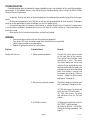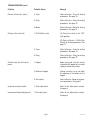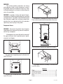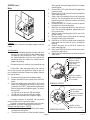
1
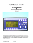
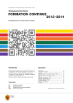
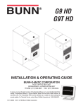
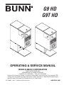
G9 HD
G9T HD
N
IO
UT RY
CA INJU
AL .
ON RD
D
RS ZA
AN
PE HA ERS CTS
JE
FINGOB ER
EP N PP G.
KE REIG HO ENIN
FO T OFE OP
OU UT
CH
OR
N
IO
UT RY
CA INJU
AL .
ON RD
D
RS ZA
AN
PE HA ERS CTS
JE
FINGOB ER
EP N PP G.
KE REIG HO ENIN
FO T OFE OP
OU UT
CH
OR
OPERATING & SERVICE MANUAL
BUNN-O-MATIC CORPORATION
POST OFFICE BOX 3227
SPRINGFIELD, ILLINOIS 62708-3227
PHONE: (217) 529-6601 FAX: (217) 529-6644
To obtain the Illustrated Parts Catalog, visit the Bunn-O-Matic website, at www.bunn.com. This is absolutely FREE,
and the quickest way to obtain the catalog. Contact Bunn-O-Matic Corporation at 1-800-286-6070 to obtain a paper
copy of the required Illustrated Parts Catalog mailed via U.S. Postal Service.
10171.0000M
04/07 © 1986 Bunn-O-Matic Corporation
www.bunn.com
CONTENTS
Introduction----------------------------------------------------- 2
Warranty-------------------------------------------------------- 2
User Notices---------------------------------------------------- 3
Electrical Requirements--------------------------------------- 3
Initial Set Up---------------------------------------------------- 3
Operating Controls--------------------------------------------- 3
Cleaning--------------------------------------------------------- 4
Coffee Grinding------------------------------------------------- 4
Adjustments---------------------------------------------------- 4
Troubleshooting------------------------------------------------ 6
Service---------------------------------------------------------- 8
Wiring Diagram------------------------------------------------ 14
INTRODUCTION
This equipment will store up-to nine pounds of whole bean coffee and grind it to a preset grind and amount into an
awaiting funnel and filter from most commercial drip coffee brewers. The equipment is only for indoor use on a sturdy
counter or shelf. Adequate space must be available above the grinder to raise the lid when adding beans. Use only with
whole bean coffee.
The grind is preset at the factory to drip specifications as set forth by the United States Department of Commerce and
adopted by the Coffee Brewing Center of the Pan American Coffee Bureau. Adjustments may be made to alter both the
amount and grind from the factory setting.
BUNN-O-MATIC COMMERCIAL PRODUCT WARRANTY
Bunn-O-Matic Corp. (“BUNN”) warrants equipment manufactured by it as follows:
1) All equipment other than as specified below: 2 years parts and 1 year labor.
2) Electronic circuit and/or control boards: parts and labor for 3 years.
3) Compressors on refrigeration equipment: 5 years parts and 1 year labor.
4) Grinding burrs on coffee grinding equipment to grind coffee to meet original factory screen sieve analysis: parts and
labor for 3 years or 30,000 pounds of coffee, whichever comes first.
These warranty periods run from the date of installation. BUNN warrants that the equipment manufactured by it will
be commercially free of defects in material and workmanship existing at the time of manufacture and appearing within the
applicable warranty period. This warranty does not apply to any equipment, component or part that was not manufactured
by BUNN or that, in BUNN’s judgment, has been affected by misuse, neglect, alteration, improper installation or operation,
improper maintenance or repair, damage or casualty. This warranty is conditioned on the Buyer 1) giving BUNN prompt
notice of any claim to be made under this warranty by telephone at (217) 529-6601 or by writing to Post Office Box 3227,
Springfield, Illinois 62708-3227; 2) if requested by BUNN, shipping the defective equipment prepaid to an authorized BUNN
service location; and 3) receiving prior authorization from BUNN that the defective equipment is under warranty.
THE FOREGOING WARRANTY IS EXCLUSIVE AND IS IN LIEU OF ANY OTHER WARRANTY, WRITTEN OR ORAL, EXPRESS
OR IMPLIED, INCLUDING, BUT NOT LIMITED TO, ANY IMPLIED WARRANTY OF EITHER MERCHANTABILITY OR FITNESS
FOR A PARTICULAR PURPOSE. The agents, dealers or employees of BUNN are not authorized to make modifications to
this warranty or to make additional warranties that are binding on BUNN. Accordingly, statements by such individuals,
whether oral or written, do not constitute warranties and should not be relied upon.
If BUNN determines in its sole discretion that the equipment does not conform to the warranty, BUNN, at its exclusive
option while the equipment is under warranty, shall either 1) provide at no charge replacement parts and/or labor (during
the applicable parts and labor warranty periods specified above) to repair the defective components, provided that this
repair is done by a BUNN Authorized Service Representative; or 2) shall replace the equipment or refund the purchase price
for the equipment.
THE BUYER’S REMEDY AGAINST BUNN FOR THE BREACH OF ANY OBLIGATION ARISING OUT OF THE SALE OF THIS
EQUIPMENT, WHETHER DERIVED FROM WARRANTY OR OTHERWISE, SHALL BE LIMITED, AT BUNN’S SOLE OPTION
AS SPECIFIED HEREIN, TO REPAIR, REPLACEMENT OR REFUND.
In no event shall BUNN be liable for any other damage or loss, including, but not limited to, lost profits, lost sales,
loss of use of equipment, claims of Buyer’s customers, cost of capital, cost of down time, cost of substitute equipment,
facilities or services, or any other special, incidental or consequential damages.
Page 10171 042707
USER NOTICES
Carefully read and follow all notices on the grinder and in this manual. They were written for your protection.
All notices on the grinder are to be kept in good condition. Replace any unreadable or damaged labels.
WARNING
Use only on a properly protected circuit
capable of the rated load.
Electrically ground the chassis.
Follow national/local electrical codes.
Do not use near combustibles.
An extension cord, when used, must be shorter
than 20 feet if 16-gage 3-conductor wire, or
shorter than 10 feet if 18-gage 3-conductor wire.
FAILURE TO COMPLY RISKS EQUIPMENT
DAMAGE, FIRE, OR SHOCK HAZARD
#37881.0000
READ THE ENTIRE OPERATING MANUAL
INCLUDING THE LIMIT OF WARRANTY AND
LIABILITY BEFORE BUYING OR USING THIS PRODUCT
PERSONAL INJURY
HAZARD.
20545-0000D 01/04 © 1990 Bunn-O-Matic Corporation
#20545.0000
KEEP FINGERS AND
FOREIGN OBJECTS
OUT OF HOPPER
OR CHUTE OPENING.
#05876.0000
ELECTRICAL REQUIREMENTS
This grinder has an attached cordset and requires 2-wire, grounded service rated 120 volts ac, 15 amp, single
phase, 60 Hz or 2 wire, grounded service rated 220-240 volts ac, 4.7 amp, single phase, 50 Hz.
INITIAL SET UP
1. Open the top lid. Clear all foreign objects and shipping materials from the hopper compartment and the
entrance to the grind chamber.
2. Fill hopper compartment with whole bean coffee. (Capacity 9 pounds). The grinder is now ready for use.
OPERATING CONTROLS
Off/On/Start Switch
OFF - (left position)
Placing the switch in this position stops the operation of the grinder.
ON - (center, resting position)
The switch will return to this position after a grind cycle has begun and
will remain in this position after grinding has ceased.
START - (right, momentary position)
Placing the switch in this position initiates a timed grind cycle.
URN
ON
O
F
F
S
T
A
R
T
CARAFE
P1300
Batch Selector Switch (Optional)
URN - Switching to this position allows the correct amount of beans to be dispensed when grinding a
large batch.
CARAFE - Switching to this position allows the correct amount of beans to be dispensed when grinding
a small batch.
Page 10171 042707
CLEANING
The use of a damp cloth rinsed in any mild, non-abrasive, liquid detergent is recommended for cleaning all
surfaces on Bunn-O-Matic equipment. Care should be taken not to scratch the windows with any abrasive material. Regular cleaning will keep your grinder looking new for years.
COFFEE GRINDING
P1301
1.
2.
3.
4.
5.
6.
STEP 1
P1302
STEP 2
P1303
STEP 3
P1304
STEP 4
P1305
STEPS 5 & 6
Visually inspect the hopper for an ample supply of whole bean coffee.
Place a paper filter into the brew funnel. The filter must not be folded-over or tilted to one side.
Insert the funnel into the funnel rails and push until it stops.
Momentarily place the switch in the “START” (right) position. The grinding action will stop automatically
after the preset amount of ground coffee is dispensed into the funnel.
Remove the funnel from the grinder and level the bed of grounds by gently shaking.
The loaded funnel is now ready for use in any commercial drip coffee brewer according to the manufacturer’s
instructions.
ADJUSTMENTS
The grind can be set from very fine to very coarse. The amount may be adjusted for use in most commercial
coffee brewers. The following procedures should be used to make adjustments. A change in the burr adjustment
will also change the amount dispensed. Any adjustment of the burrs should be followed by an adjustment of
the timer.
Burr Adjustment
1. Unplug the grinder and empty all beans from the hopper.
2. Plug-in the grinder, momentarily place the Off/On/Start switch in the
“START” (right) position, and run a few grind cycles until all of the coffee in the grind chamber is used-up.
3. Remove the upper front inspection panel.
4. Loosen the burr adjustment screw from its locked position.
5. Hand loosen the adjustment locking nut around the screw approximately one turn.
6. Place the Off/On/Start switch in the “START” (right) position and slowly
turn the adjusting screw in a clockwise direction until a metallic whine
is heard due to the rubbing of the grinding burrs. (It may be necessary
to start more than one grind cycle to obtain this sound.)
Page P581
P581
10171 041597
ADJUSTMENTS (cont.)
Burr Adjustment (cont.)
7.
8.
Make a mark with a pen on the decal to note the position of the arrow on the grind adjustment screw.
The following settings approximately correspond to the CBC recognized grinds. All are referenced from the
arrow position noted in step 7.
FINE GRIND: Rotate the adjusting screw 7 hash marks in a counterclockwise direction.
DRIP GRIND: Rotate the adjusting screw 8 hash marks in a counterclockwise direction.
REGULAR (COARSE) GRIND: Rotate the adjusting screw 12 hash marks in a counterclockwise direction.
9.
Hold the adjusting screw in its set position with a screwdriver while tightening the lock nut to a snug position by hand. Slightly loosen the adjusting screw and retighten it to its prior position. The lock nut should
now be tight against the burr housing front cover.
Timer Adjustment
NOTE: Grinders with Multi Set option (Urn/Carafe) must be adjusted in both settings.
1.
2.
3.
4.
5.
Unplug the grinder and remove the lower front inspection panel.
Determine the grind setting. (The factory setting is drip, to determine other settings, refer to the previous
section.)
Use the table below to find the approximate timer setting for the grind and amount of coffee desired.
Set the timer for the desired amount of coffee to be ground.
Verify the setting by weighing a few samples. Use the table below as an APPROXIMATE guide only.
APPROXIMATE TIMER SETTINGS IN SECONDS
WEIGHT
(OUNCES)
FINE
(7*)
DRIP
(8*)
REGULAR
(12*)
1.5
1.75
2.0
2.25
2.5
2.75
3.0
3.25
3.5
3.75
2-2/3
3
3-2/3
4
4-1/3
4-2/3
5-1/3
6
6-1/3
6-2/3
2-1/3
2-2/3
3-1/3
3-2/3
4
4-1/3
5
5-1/3
5-2/3
6-1/3
2-1/3
2-2/3
3
3-1/3
3-2/3
4
4-1/3
5
5-1/3
5-2/3
4.0
7-1/3
6-2/3
6
*Hash mark settings. Refer to Adjustment-Burr section.
Page 10171 041597
TROUBLESHOOTING
A troubleshooting guide is provided to suggest probable causes and remedies for the most likely problems
encountered. If the problem remains after exhausting the troubleshooting steps, contact the Bunn-O-Matic
Technical Service Department.
• Inspection, testing, and repair of electrical equipment should be performed only by qualified service personnel.
• All electronic components have 120 volt ac and low voltage dc potential on their terminals. Shorting of
terminals or the application of external voltages may result in board failure.
• Intermittent operation of electronic circuit boards is unlikely. Board failure will normally be permanent.
If an intermittent condition is encountered, the cause will likely be a switch contact or a loose connection at a
terminal or crimp.
• Make certain that all electrical connections are tight and isolated.
WARNING
•
•
•
•
Exercise extreme caution when servicing electrical equipment.
Turn power OFF when servicing, except when electrical tests are specified.
Follow recommended service procedures.
Replace all protective shields or safety notices.
Problem
Grinder will not start.
Probable Cause
1. Motor overload protector
2. No power or incorrect voltage
Remedy
Remove the cover plate located
on the right side of the housing.
Press the red “Reset” button. Listen
carefully for a “click”. This resets
the motor protection circuit and
indicates that an overload may have
been encountered by the motor. (An
overload can occur when something
other than coffee is inserted into
the hopper for grinding.) Refer to
Service - Motor for disassembly
procedures. See page 9.
Check the voltage at the power cord
with a voltmeter. Voltage must be:
(A) 120 volts across the black and
white wires for 120 volt models.
(B) 240 volts across the black
and red/black wires for 240 volt
models.
3. Off/On/Start switch
Page (A) Momentarily place the switch in
the “START” (right) position.
(B) Refer to Service - Off/On/Start
Switch for testing procedures. See
page 11.
10171 121597
TROUBLESHOOTING (cont.)
Problem
Grinder will not start. (cont.)
Probable Cause
Remedy
4. Timer
Refer to Service - Timer for testing
procedures. See page 13.
5. Relay
Refer to Service - Relay for testing
procedures. See page 12.
Refer to Service - Motor for testing
procedures. See page 9.
(A) Place the switch in the “OFF”
(left) position.
6. Motor
Grinder will not shut off.
1. Off/On/Start switch
2. Timer
3. Relay
Grinder starts, but will not dispense.
1. Hopper
2. Bottom of hopper
3. Shear plate
(B) Refer to Service - Off/On/Start
Switch for testing procedures. See
page 11.
Refer to Service - Timer for testing
procedures. See page 13.
Refer to Service - Relay for testing
procedures. See page 12.
Begin each grind cycle by visually
inspecting the hopper for an ample
supply of whole bean coffee.
Foreign materials must not block
the opening at the bottom of the
hopper.
Refer to Service - Motor for replacement procedures. See page 9.
Incorrect amount of coffee.
1. Timer adjustment
Refer to the Adjustments section.
See page 4.
Incorrect coffee grind dispensed.
1. Burr adjustment
Refer to the Adjustments section.
See page 4.
Page 10171 121597
SERVICE
This section provides procedures for testing
and replacing various major components used in
this grinder should service become necessary. Refer
to Troubleshooting for assistance in determining the
cause of any problem.
WARNING - Inspection, testing, and repair of electrical equipment should be performed only by qualified
service personnel. The grinder should be disconnected
from the power supply when servicing, except when
electrical tests are required and the test procedure
specifically states to plug-in the grinder.
P1306
The top lid is attached with four 6-32 screws.
These screws need only to be loosened for lid removal.
Component Access
WARNING - Disconnect the grinder from the power
supply before the removal of any panel or the replacement of any component.
All components are accessible by the removal of
the upper and lower front inspection panels, top lid,
rear panel, and hopper.
P1307
The rear panel is attached with eight 8-32 screws.
P602
The upper front inspection panel is attached with
two 6-32 screws.
P1308
The hopper/extension assembly is attached with
six 8-32 screws.
CAUTION
PERSONAL INJURY
HAZARD.
KEEP FINGERS AND
FOREIGN OBJECTS
OUT OF HOPPER
OR CHUTE OPENING.
Contents
Motor--------------------------------------------------- 9
Off/On/Start Switch-----------------------------------11
Urn/Caraffe Switch-----------------------------------11
Relay---------------------------------------------------12
Timer---------------------------------------------------13
P603
The lower front inspection panel is attached with
two 6-32 screws.
Page 10171 042707
SERVICE (cont.)
Motor
3.
4.
5.
6.
7.
BLY
E
FIN
EMPT UG
THORO
E
C
11191.0001
NOTI
F T
O H
R IS
E
C
R OV
EA E
S S R.
EM
SE
AR
CO
G
IN E
V B
OR
Y
EM E
H
HL OPPER BEFORE RAMB
YC
LEAN GRIND CH
IO
N
UT URY
CA INJ
AL
ON D.
RS ZAR S AND
S
PE HA
8.
GER ECT
R
P FINN OBJ
PPE G.
KEE EIG HO NIN
FORT OF OPE
OU TE
CHU
OR
9.
P1309
10.
Location:
The motor is located in the upper wrapper under the
hopper.
11.
Test Procedure:
1. Remove the hole plug located on the right side of the
housing. Press the red “Reset” button visible through
the opening. Listen carefully for a “click”. This resets
the motor protection circuit and may indicate that
something other than coffee was inserted into the
hopper for grinding.
2.
12.
13.
of the grinder housing through the hole in the motor
mounting plate.
Remove both 6-32 screws beneath the upper front
inspection panel.
Remove the six 10-32, hex head screws on top of the
motor mounting plate.
Slowly slide the assembly out the rear of the grinder
housing. The mounting plate will have to be raised
to gain clearance for the motor hardware and wiring
harness bushing.
Remove the four 5/16”-18 bolts and nuts to separate
the motor from the mounting plate.
Mount the new motor and tighten the four bolts and
nuts. They should be tightened approximately one
full turn past snug.
Slide the motor mounting plate into the rear of the
grinder housing.
Feed the wiring harness into the top of the housing
through the hole in the motor plate.
Reinstall the six 10-32 hex head screws through the
motor plate and the two 6-32 screws through the
housing.
Reattach the green wire to the 10-32 stud on the
motor mounting plate.
Refer to the Off/On/Start switch section when reconnecting the switch wires.
Refer to the illustration below when reconnecting the
motor wires.
WHI/ BLU to Snubber
WHI/BLU to Relay
WHI/BLK to Cordset
(120V models)
RED/BLK to Cordset
(230V models)
If the grinder remains unable to start, proceed to step
If the grinder stops operating shortly after starting,
refer to the removal and replacement steps to gain access-to the grind chamber. Remove any foreign materials
that may be found.
2.
3.
4.
5.
WHI/BLK to Snubber
GRN to Chasis Ground
YEL to Snubber
Disconnect the grinder from the power supply.
Remove the electrical access panel at the rear of the
motor.
Check the voltage across terminals L1 & L2 of the
motor with a voltmeter when the Off/On/Start switch
is placed in the “START” (right) position and released.
Connect the grinder to the power supply. The indication must be:
(a) 120 volts ac for two wire 120 volt models.
(b) 240 volts ac for two wire 240 volt models.
Disconnect the grinder from the power supply.
FRANKLIN MOTOR
WHI/BLK to Snubber
YEL to Snubber
WHI/ BLU to Snubber
WHI/BLK to Cordset
If voltage is present as described and the grinder
remains unable to start, replace the motor.
If voltage is not present as described, refer to the Wiring Diagrams, and check the grinder wiring harness.
Removal and Replacement - MOTOR
1. Remove all wires from the Off/On/Start switch, motor,
and motor mounting plate.
2. The entire wiring harness must be fed into the bottom
MARATHON MOTOR
Page WHI/BLU to Relay
GRN to Chasis Ground
P621
10171 042707
SERVICE (cont.)
Motor (cont.)
9
8
7
6
5
4
3
2
1
P1311
1.
2.
3.
4.
5.
6.
7.
8.
9.
Adjusting Screw Locknut
Adjusting Screw
Burr Housing Cap
Rotor Cup
Shear Plate
Removal and Replacement - GRIND CHAMBER
1. Refer to the illustration above and remove the
two 1/4”-20, hex head screws holding the burr
housing cap(3) to the burr housing; carefully remove the burr housing cap. Inspect the adjusting
screw(2) to see if the thrust plug is worn.
Replace if excessively worn or damaged.
2. Carefully remove rotor cup(4), shear plate(5),
and burr rotor(6) from the grinder. Inspect the
shear plate and burr(8) for wear.
Replace if excessively worn or damaged.
3. Remove and inspect stationary burr(9) for
wear.
Replace if excessively worn or damaged.
4.
5.
6.
Rotor
Spring
Burr (Rotating)
Burr (Stationary)
Inspect the grind chamber and remove any foreign materials. The burrs will not properly seat
in the chamber if any material or coffee particles
remain.
Reinstall the stationary burr, spring, burr rotor,
shear plate, rotor cup, and burr housing cap to
the burr housing.
Refer to the Adjustments section to vary the grind
dispensed.
NOTE: Burrs must be replaced as a set.
Page 10
10171 041597
SERVICE (cont.)
If continuity is present as described, the Off/On/Start
switch is operating properly.
If continuity is not present as described, replace the
switch.
Off/On/Start Switch
Removal and Replacement:
1. Remove all wires from the switch terminals.
2. Compress the clips inside the front wrapper and
gently push the switch through the opening.
3. Push the new switch into the opening and spread
the clips to hold the switch captive in the hood.
4. Refer to the illustration below when reconnecting
the wires.
URN
ON
S
T
A
R
T
O
F
F
CARAFE
P1300
Location:
The Off/On/Start switch is centered in the housing
above the upper front inspection panel.
WHI/YEL to Timer TL5
WHI/ORA to Timer TL3
Test Procedure:
1. Disconnect the grinder from the power supply.
2. Remove the black wire from the switch.
3. Check for continuity across the black wire from the
Off/On/Start switch and the left blade of the cordset
connector (see illustration below).
WHI/RED to Timer TL1
P606
Urn/Carafe Switch
CORDSET CONNECTOR
Looking Strait-on
Black
BLK to Cordset
Location:
The Urn/Carafe switch is located to the left side on
the front of the housing above the upper inspection
panel.
White
Ground
If continuity is present as described, proceed to step
4.
If continuity is not present as described, refer to the
Wiring Diagrams and check the grinder wiring harness.
4. Remove the remaining wires from the switch.
5. Check for continuity across the lower terminals
when the switch is placed in both the “ON” (center)
and “START” (right) positions.
If continuity is present as described, proceed to step
6.
If continuity is not present as described, replace the
switch.
6. Check for continuity across the upper terminals
when the switch is placed in the “START” (right)
position only.
Test Procedure:
1. Disconnect the grinder from the power supply.
2. Remove the tan, yellow and green wires from the
switch.
3. Place the switch in the “CARAFE” position; check
for continuity across the pink and the tan wire
terminals, also across the orange and the yellow
wire terminals.
If continuity is present as described in both checks,
proceed to step 4.
If continuity is not present as described in one or both
of the checks, replace the switch.
4. Place the switch in the “URN” position; check for
continuity across the orange and green wire terminals.
If continuity is present as described, the switch is
operating properly.
Page 11
10171 041597
SERVICE (cont.)
If continuity is not present as described, replace
the switch.
Removal and Replacement:
1. Remove all the wires from the switch terminals.
2. Compress the clips inside the housing and gently
push the switch through the opening.
3. Push the new switch into the opening and spead
the clips to hold the switch in the housing.
4. Refer to the illustration below when reconnecting
the wires.
3.
If voltage is present as described, reconnect the
white/red and white/green wires to the relay coil, and
proceed to step 4.
If voltage is not present as described, refer to
the Wiring Diagrams and check the grinder wiring
harness.
4.
TAN
YEL
PNK
ORA
5.
GRN
6.
P1318
Remove the white/red and white/blue wires from
the relay contacts.
Check for continuity across the relay contacts
when the Off/On/Start switch is placed in the
“START” (right) position and released. Connect
grinder to the power supply. Continuity must
be present for the approximate setting on the
timer.
Disconnect the grinder from the power supply.
If continuity is present as described, reconnect the
white/red and white/blue wires, the relay is operating
properly.
If continuity is not present as described, replace
the relay.
Relay
Removal and Replacement
1. Remove all wires from the relay terminals.
2. Remove the 6-32 screw fastening the relay to the
timer bracket.
3. Mount the new relay to the timer bracket and
tighten the screw.
4. Refer to the illustration below when reconnecting the wires.
ES
UT ATIC C
MIN -M 0 VA
-O
NN 12
BU 2026
P/N
Single set timer shown
Multi set timer (Urn/Carafe) similar
when the Off/On/Start switch is placed in the
“START” (right) position and released. Connect
grinder to the power supply. The indication must
be:
(a) 120 volts ac for two wire 120 volt models
(b) 240 volts ac for two wire 240 volt models
for the approximate setting on the timer.
Disconnect the grinder from the power supply.
P1312
WHI/BLU to Motor L1
Location:
The relay is located on the timer bracket in the
grinder base. The bracket can be removed by loosening the two 8-32 screws beneath the timer dial.
Test Procedure:
1. Disconnect the grinder from the power supply.
2. Check the voltage across the white/red and white/
green wires of the relay coil with a voltmeter
WHI/GRN to Timer L4
ES
UT ATIC C
MIN-O-M 0 VA
NN 12
BU 2026
P/N
Page 12
WHI/RED to Timer TL1
P610
10171 121597
SERVICE (cont.)
6.
Timer
Check the voltage across terminals TL1 and TL4
with a voltmeter when the Off/On/Start switch
is placed in the “START” (right) position and
released. Connect grinder to the power supply.
The indication must be:
(a) 120 volts ac for two wire 120 volt models.
(b) 240 volts ac for two wire 240 volt models.
7.
Disconnect the grinder from the power supply.
S
UTEATIC C
MIN-O-M 0 VA
NN 12
BU 2026
P/N
Single set timer shown
Multi set timer (Urn/Carafe) similar
If voltage is present as described, the timer is
operating properly. Refer to the Adjustments section
to vary the amount dispensed.
If voltage is not present as described, replace
the timer.
P1312
Location:
The timer is located on the timer bracket in the
grinder base. The bracket can be removed by loosening the two 8-32 screws beneath the timer dial(s).
Test Procedure:
1. Disconnect the grinder from the power supply.
2. Check the voltage across terminals TL1 & TL2
with a voltmeter when the “Off/On/Start switch
is placed in the “START” (right) position and
released. Connect grinder to the power supply.
The indication must be:
(a) 120 volts ac for two wire 120 volt models.
(b) 240 volts ac for two wire 240 volt models.
3. Disconnect the grinder from the power supply.
Removal and Replacement:
1. Remove all wires from the timer terminals.
2. Remove the four 6-32 screws and nuts holding
the circuit board to the timer bracket.
3. Remove the two 6-32 screws and nuts holding
the dial plate to the timer bracket.
4. Install the new dial plate and circuit board to the
timer bracket.
5. Refer to the illustration below when reconnecting
the wires.
6. Refer to the Adjustments section to vary the
amount dispensed.
If voltage is present as described, proceed to
step 4.
If voltage is not present as described, refer to
the Wiring Diagram and check the grinder wiring harness.
4.
5.
Remove the white/orange and white/yellow wires
from terminals TL3 & TL5.
Check for continuity across the white/orange and
white/yellow wires when the Off/On/Start switch
is placed in the “START” (right) position.
If continuity is present as described, reconnect
the white/orange wire to terminal TL3 and the white/
yellow wire to terminal TL5, and proceed to step 6.
If continuity is not present as described, refer
to the Wiring Diagram and check the grinder wiring
harness.
Page 13
WHI/RED to Relay N.O.
WHI/RED to
Off/On/Start Switch
2
WHI to Cordset (120 v)
RED/BLK to Cordset (240 v)
3
4
M
B IN
P/NUNN UTE
5
26 -O-M S
20
- ATIC
12
0V
AC
WHI/ORA to
Off/On/Start Switch
WHI/GRN to Relay Coil
WHI/YEL to
Off/On/Start Switch
Single set timer shown
Multi set timer (Urn/Carafe) connections are the same
P1313
10171 121597
WIRING DIAGRAM
SCHEMATICWIRINGDIAGRAMG9
GREEN
L1
BLK
N
WHI/RED
W
WHI/YEL
H
I
/
O
R
WHI/ORA
A
OPTIONAL KEY SW
120VOLTSAC
2WIRE
SINGLEPHASE
60HZ
WHI
WHI/RED
WHI/RED
WHI/GRN
K1
WHI/BLU
L1
K1 N.O.
M
WHI
L2
1 2 3 4 5
TIMER
10173-0000F 4/91 © 1987 BUNN-O-MATIC CORPORATION
SCHEMATICWIRINGDIAGRAM
G9-URN/CARAFE
GREEN
L1
BLK
N
WHI/RED
WHI
WHI/RED
WHI/YEL
WHI/ORA
WHI/RED
WHI/GRN
K1
K1 N.O.
1 2 3 4 5
TIMER
ORA
120VOLTSAC
2WIRE
SINGLEPHASE
60HZ
WHI/BLU
L1
M
WHI
L2
BRN
ORA
PIN
YEL
YEL
GRN
GRN
URN
CARAFE
MULTI-SET SW
(OPTIONAL)
TAN
10215.0000C 4/97 © 1987 BUNN-O-MATIC CORPORATION
Page 14
10171 041597
SCHEMATICWIRINGDIAGRAMG9AHD
GREEN
L1
BLK
L2
WHI/RED
RED/BLK
WHI/RED
WHI/RED
WHI/YEL
WHI/ORA
200VOLTSAC
2WIRE
SINGLEPHASE
50HZ
WHI/GRN
K1
WHI/BLU
L1
K1 N.O.
M
RED/BLK
L2
1 2 3 4 5
TIMER
10187-0000B 11/97 © 1987 BUNN-O-MATIC CORPORATION
SCHEMATICWIRINGDIAGRAMG9AHD
POWER
INDICATOR LIGHT
RED/BLK
WHI/RED
L1
BLK
GREEN
L2
WHI/RED
RED/BLK
WHI/RED
WHI/YEL
WHI/ORA
200VOLTSAC
2WIRE
SINGLEPHASE
50HZ
WHI/GRN
WHI/RED
K1
WHI/BLU
K1 N.O.
L1
M
RED/BLK
L2
1 2 3 4 5
TIMER
10187.0001B 11/97 © 1997 BUNN-O-MATIC CORPORATION
Page 15
10171 121597
WIRING DIAGRAM
SCHEMATIC WIRING DIAGRAM G9
GREEN
L1
BLK
N
WHI/RED
W
WHI/YEL
H
I
/
O
R
WHI/ORA
A
OPTIONAL KEY SW
WHI
WHI/RED
WHI/BLU
WHI/RED
WHI/GRN
K1
L1
K1 N.O.
WHI
M
L2
1 2 3 4 5
ORA
TAN
GRY
TIMER
120 VOLTS AC
2 WIRE
SINGLE PHASE
60 HZ
PNK
10388-0000B 12/88 © 1988 BUNN-O-MATIC CORPORATION
PNK
1 2 3 4
OPTIONAL BREWER
INTERFACE CONNECTOR
OPTIONAL
MULTI-SET SW
SCHEMATIC WIRING DIAGRAM G9
GREEN
L1
BLK
WHI/RED
WHI
WHI/RED
OPTIONAL KEY SW
WHI/RED
WHI/YEL
WHI/ORA
WHI/ORA
120 VOLTS AC
2 WIRE
SINGLE PHASE
60 HZ
WHI/GRN
N
K1
WHI/BLU
K1 N.O.
L1
M
WHI
L2
1 2 3 4 5
TAN
TIMER
GRY
PNK
OPTIONAL BREWER
INTERFACE CONNECTOR
1 2 3 4
10388-0001C 11/91 © 1991 BUNN-O-MATIC CORPORATION
Page 16
10171 021599