1
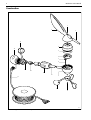
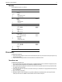
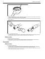
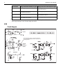
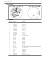
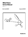
Wind Vane
Service Manual
Document number: 83170-1
15 May 2004
Short arm E22078
Long arm E22079
D7006-1
© Manual contents copyright Raymarine Ltd 2004.
Raymarine® is a registered trademark of Raymarine Holdings.
Wind Vane
Service Manual
Contents
Introduction .......................................................................................................................................................................... 3
Safety ...........................................................................................................................................................................3
Overview ......................................................................................................................................................................3
Tools & test equipment .................................................................................................................................................3
Construction ..........................................................................................................................................................................4
Parts list ........................................................................................................................................................................5
Disassembly.......................................................................................................................................................................... 5
Transducer arm .............................................................................................................................................................5
Wind vane base ............................................................................................................................................................6
Reassembly ...........................................................................................................................................................................6
Wind vane base ............................................................................................................................................................6
Transducer arm .............................................................................................................................................................7
Testing ...................................................................................................................................................................................7
PCB .......................................................................................................................................................................................8
Circuit diagram .............................................................................................................................................................8
Layout diagram ............................................................................................................................................................9
Component List ............................................................................................................................................................9
Wind Vane Service Manual
3
Introduction
Safety
WARNING: Product servicing
The wind vane must be serviced in accordance with the Raymarine instructions provided. Failure
to do so could result in poor product performance, personal injury and/or damage to the boat.
WARNING: Electrical safety
Always switch off the power supply before you work on Raymarine products.
CAUTION: Electrostatic Discharge
The wind vane contains electrostatic sensitive components. Always observe the appropriate
precautions when handling, shipping, and storing these products. Failure to do this could result in
permanent damage to the equipment.
Overview
This manual provides servicing information for the Raymarine short-arm and long-arm wind vanes, part numbers E22078
and E22079, respectively. The following information is provided:
• Tools and test equipment.
• An exploded view of the wind vane.
• A list of replaceable parts.
• Disassembly and assembly instructions.
• Functional tests.
• Wind vane PCB circuit, layout and parts.
Tools & test equipment
The following tools and test equipment are required:
• Two small Pozidriv screwdrivers.
• One small flat-blade screwdriver.
• Serviceable ST60 Wind instrument.
• 12 V power supply.
• Multimeter.
4
Wind Vane Service Manual
Construction
1
2
3
18
4
16
5
6
7
8
15
14
13
12
9
17
10
11
D6958-1
Figure 1:
New Wind Vane exploded view
Wind Vane Service Manual
5
Parts list
The New Wind Vane parts are as follows:
:
Item
Description
Part No.
A28167
1 & 11
2
3
10
Wind vane kit
comprises:
Screws
Vane
Counterbalance weight
Anemometer cups
A28168
5
Top Pod
includes:
bearing
magnet assembly
O-ring seal
6
PCB assembly
A28164
7
8
14
Transducer arm cable assembly:
either 300 mm
or
600 mm
comprises:
upper connector
cable
lower connector
4
12
9
13
Transducer arm:
either Short arm (300mm)
or
Long arm (600mm)
includes fitted:
bottom pod
locking ring
O-ring (not illustrated)
16
Wind transducer base
15
17
Cable and connector assembly:
either 30m cable
or
50m cable
comprises:
nut
cable
18
Connector cap
A28165
A28166
A28159
A28160
A28161
A28162
A28163
R28169
Disassembly
To dismantle the wind vane:
1. Unscrew the locking ring (item 13) that secures the transducer arm (item 12) to the wind vane base (item 16), then separate these two items.
2. Carry out the disassembly instructions for the transducer arm and wind vane base.
Transducer arm
To dismantle the transducer arm:
1. Remove and retain the screw (item 1) that secures the assembled wind vane (item 2) and balance weight (item3) to the
top pod (item 4) shaft, then pull the vane and balance weight from the shaft.
2. Remove and retain the screw (item 11) that secures the anemometer cups (item 10) to the bottom pod (item 9) shaft,
then pull the cups from the shaft.
3. Unscrew the top and bottom pods from one another. If necessary, use a suitable tool to engage with the holes in the top
pod, to facilitate this.
4. Remove the O-ring seal (item 5).
5. Referring to Figure 2 , insert a suitable tool (e.g. small screwdriver) into the breakout holes at the edge of the PCB
(item 6), then use the tool to GENTLY ease the PCB from its recess in the bottom pod.
6
Wind Vane Service Manual
D6959-1
Figure 2:
Easing out PCB
6. Separate the PCB from the bottom pod just sufficiently to gain access to the upper connector (item7) on the transducer
arm cable assembly, then disconnect the connector from the PCB.
7. At the lower end of the transducer arm, press in both clips to release the lower connector (item 14) from the transducer
arm (see Figure 3 ).
D6960-1
Figure 3:
Releasing lower connector
8. Carefully guide the upper connector (item 7) on the transducer arm cable assembly, out of the bottom pod, then withdraw the complete transducer arm cable assembly through the bottom of the transducer arm.
Wind vane base
To dismantle the wind vane base (item 16):
1. Using a suitable tool, remove and retain the nut (item 15) that secures the cable connector in the wind vane base.
2. Withdraw the transducer cable and connector through the bottom of the wind vane base.
Reassembly
Wind vane base
To reassemble the wind vane base:
1. Ensuring that the key on the transducer cable connector engages with the respective keyway on the wind vane base,
insert the connector through the bottom of the wind vane base into the correct position in the base.
2. Using a suitable tool, secure the connector in the base with the nut retained during disassembly. Tighten the nut until
its front edge is flush with the upper face of the connector.
Wind Vane Service Manual
7
Transducer arm
To reassemble the transducer arm:
1. Fit the transducer arm cable assembly as follows:
i. Arrange the upper connector of the transducer arm cable assembly as shown in Figure 4 .
D6962-1
Figure 4:
2.
3.
4.
5.
6.
7.
Cable/connector arrangement
ii. Feed the transducer arm cable assembly upper connector though the bottom of the arm, then up the arm and into
the bottom pod.
iii. Ensuring that the key on the lower connector of the transducer arm cable assembly is aligned with the keyway on
the arm, push the lower connector into the bottom of the arm, until both clips engage, to secure the connector in
the arm.
iv. Connect the upper connector of the transducer arm cable assembly to the appropriate connector on the PCB.
With the PCB connector adjacent to the cable entry hole on the top pod, place the PCB in its recess in the bottom pod,
ensuring that the cut-aways in the PCB engage with the respective protrusions on the lower pod.
Check the condition of the O-ring seal (item 5) and if it has been damaged, obtain a new one.
Fit the O-ring seal into the groove above the thread on the top pod.
Screw the top and bottom pods together and secure tightly, to ensure a waterproof seal. If necessary, use a suitable tool
to engage with the holes in the top pod, to facilitate this.
Ensuring that the flats on the anemometer cups and the lower pod shaft are aligned, slide the anemometer cups on to
the lower pod shaft then secure with the screw removed during disassembly.
Ensuring that the flats on the vane and the upper pod shaft are aligned, slide the vane to the upper pod shaft then
secure with the screw removed during disassembly.
Testing
To check that a wind vane is serviceable:
1. Connect the wind vane to a serviceable ST60 Wind instrument as in Figure 5 .
+12 V
0V
Red
Screen
Screen
Yellow
Blue
Green
Red
D6961-1
Figure 5:
Test connections
2. At the ST60 Wind instrument, check that the voltage between the red and black connections is 8 V dc, ±0.25 V:
3. Rotate the vane to the forward, starboard, aft and port orientations in turn and, at the instrument, check the sine and
cosine signals by measuring the voltages as follows:
8
Wind Vane Service Manual
Vane direction
Voltage between Blue & Black (sine signal) Voltage between Green & Black (cosine signal)
Pointing forward
Half the supply voltage measured at step 2.
Half the supply voltage as measured at step 2 plus at least
1 V but not more than 2 V.
Pointing to starboard
Half the supply voltage as measured at step 2 plus at
least 1 V but not more than 2 V.
Half the supply voltage measured at step 2.
Pointing aft
Half the supply voltage measured at step 2.
Half the supply voltage as measured at step 2 minus at
least 1 V but not more than 2 V.
Pointing to port
Half the supply voltage as measured at step 2 minus
at least 1 V but not more than 2 V.
Half the supply voltage measured at step 2.
4. SLOWLY rotate the anemometer cups and check that the voltage between the yellow and black connections switches
between approximately 8 V and 3.2 V, twice during each rotation.
PCB
Circuit diagram
Do NOT attempt to replace or otherwise disturb IC4.
The correct physical alignment of this component is of
critical importance.
D6956-1 (From Drawing No. 4531-002G)
Wind Vane Service Manual
9
Layout diagram
D6957-1 (From Drawing No. 4531-001B)
Component List
Reference
Part No.
Description
3015-329-C
WIND TX PCB
C2
93CKEIXXX10U
CAP CER 10uF 16V
C6
93ADHBXX10N
CAP. 10nF XR7
C7
93ADHBXX10N
CAP. 10nF XR7
C8
93CKEIXXX10U
CAP CER 10uF 16V
C9
93ADHBXX10N
CAP. 10nF XR7
C12
93ADHBXX10N
CAP. 10nF XR7
C13
93ADHBXX10N
CAP. 10nF XR7
C14
93ADHBXX10N
CAP. 10nF XR7
C15
93ADHBXX10N
CAP. 10nF XR7
D1
9200BAT54
BAT54 SCHOTTKY DIODE
D2
9200ES2B
DIODE ES2B
D3
9200ES2B
DIODE ES2B
D4
9200ES2B
DIODE ES2B
D5
9200ES2B
DIODE ES2B
D6
9200ES2B
DIODE ES2B
D7
9200ES2B
DIODE ES2B
IC1
9400TS914
QUAD OPAMP
IC4
94002SA10
DUAL AXIS HALL Do NOT attempt to replace or otherwise disturb IC4
IC5
9400TCPT1200
OPTO SURFACE MOUNT
L1
9600L1
CHIP INDUCTOR
L2
9600L1
CHIP INDUCTOR
L3
9600L1
CHIP INDUCTOR
PL1
9600MOL53398
CONNECTOR
R1
91AAAXX470R
RESISTOR 470R,1% 0.063W 0603
10
Wind Vane Service Manual
Reference
Part No.
Description
R2
91AAAXXX33K
RESISTOR 33K,0.063W,0603
R3
91AAAXXX27K
RESISTOR 27K 1% 0.063W
R4
91AAAXXX33K
RESISTOR 33K,0.063W,0603
R5
91AAAXXX27K
RESISTOR 27K 1% 0.063W
R11
91AAAXXX4K7
RESISTOR 4.7K,1% 0.063W 0603
R12
91AAAXXX4K7
RESISTOR 4.7K,1% 0.063W 0603
R13
91AAAXXX33K
RESISTOR 33K,0.063W,0603
R14
91AAAXXX27K
RESISTOR 27K 1% 0.063W
R15
91AAAXXX33K
RESISTOR 33K,0.063W,0603
R16
91AAAXXX27K
RESISTOR 27K 1% 0.063W
R17
91AAAXXX16K
RESISTOR 16K,1%,0.063W, 0603
R19
91AAAXX270R
RES. 270R, 1%, 0.063W, 0603
R23
91AAAXXX1K2
RESISTOR - 1K2 1% 0603
R24
91AAAXXX1K2
RESISTOR - 1K2 1% 0603
R25
91AAAXXX1K2
RESISTOR - 1K2 1% 0603
R26
91010R0
ZERO OHM LINK, 0603 PACKAGE
R27
91010R0
ZERO OHM LINK, 0603 PACKAGE
R28
91AAAXX270R
RES. 270R, 1%, 0.063W, 0603
TR1
9500IMZ1
DUAL TRANSISTOR ARRAY
V1
9108VC180400
TRANSIENT VOLTAGE SUPRESSOR