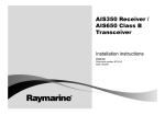
1
Shor t & long
a r m w in d v a n e
Installation instructions
English
Date: 06-2014
Document number: 87220-1-EN
© 2014 Raymarine UK Limited
Trademark and patents notice
Autohelm, hsb2, RayTech Navigator, Sail Pilot, SeaTalk, SeaTalkNG, SeaTalkHS and Sportpilot are registered
trademarks of Raymarine UK Limited. RayTalk, Seahawk, Smartpilot, Pathfinder and Raymarine are
registered trademarks of Raymarine Holdings Limited.
FLIR is a registered trademark of FLIR Systems, Inc. and/or its subsidiaries.
All other trademarks, trade names, or company names referenced herein are used for identification only
and are the property of their respective owners.
This product is protected by patents, design patents, patents pending, or design patents pending.
Fair Use Statement
You may print no more than three copies of this manual for your own use. You may not make any further
copies or distribute or use the manual in any other way including without limitation exploiting the manual
commercially or giving or selling copies to third parties.
Software updates
Check the website www.raymarine.com for the latest software releases for your product.
Product handbooks
The latest versions of all English and translated handbooks are available to download in PDF format from the website
www.raymarine.com.
Please check the website to ensure you have the latest handbooks.
Copyright ©2014 Raymarine UK Ltd. All rights reserved.
ENGLISH
Document number: 87220-1
Date: 06-2014
Contents
Chapter 1 Important information........................ 7
Chapter 10 Spares and accessories .................. 35
Certified Installation ................................................... 7
Water ingress ............................................................ 7
10.1 Wind vane spares and accessories ..................... 36
Disclaimer ................................................................. 7
EMC installation guidelines ........................................ 7
Suppression ferrites ................................................... 7
Connections to other equipment ................................. 8
Declaration of conformity............................................ 8
Product disposal ........................................................ 8
Warranty registration.................................................. 8
IMO and SOLAS........................................................ 8
Technical accuracy .................................................... 8
Chapter 2 Document and product
information........................................................... 9
2.1 Document information .......................................... 10
2.2 Further information............................................... 10
Chapter 3 Planning the installation ................... 11
3.1 Installation checklist ............................................. 12
3.2 Compatible instrument displays............................. 12
3.3 Parts supplied...................................................... 13
3.4 Tools required ...................................................... 13
3.5 Typical system ..................................................... 14
3.6 Warnings and cautions ......................................... 15
3.7 Wind vane transducer / rotavecta location
requirements ............................................................. 15
3.8 Product dimensions.............................................. 16
Chapter 4 Mounting............................................. 17
4.1 Replacing an existing wind vane ........................... 18
4.2 Mounting the junction box ..................................... 18
4.3 Surface mounting................................................. 19
Chapter 5 Cables and connections.................... 21
5.1 General cabling guidance ..................................... 22
5.2 Cable routing ....................................................... 22
5.3 Junction box connections...................................... 23
5.4 Wind vane connections ........................................ 23
Chapter 6 Operation ............................................ 25
6.1 Calibration and linearization.................................. 26
6.2 Further information............................................... 26
Chapter 7 Maintenance ....................................... 27
7.1 Routine checks .................................................... 28
7.2 Unit cleaning instructions ...................................... 28
Chapter 8 Technical support .............................. 29
8.1 Raymarine customer support ................................ 30
Chapter 9 Technical specification...................... 31
9.1 Physical specification – short arm wind vane ........... 32
9.2 Physical specification – long arm wind vane ........... 32
9.3 Conformance specification.................................... 33
5
6
Short & Long Arm Wind Vane
Chapter 1: Important information
Certified Installation
Raymarine recommends certified installation by a
Raymarine approved installer. A certified installation
qualifies for enhanced product warranty benefits.
Contact your Raymarine dealer for further details,
and refer to the separate warranty document packed
with your product.
Warning: Product installation and
operation
Disclaimer
Raymarine does not warrant that this product is
error-free or that it is compatible with products
manufactured by any person or entity other than
Raymarine.
Raymarine is not responsible for damages or injuries
caused by your use or inability to use the product,
by the interaction of the product with products
manufactured by others, or by errors in information
utilized by the product supplied by third parties.
EMC installation guidelines
Warning: Potential ignition source
Raymarine equipment and accessories conform to
the appropriate Electromagnetic Compatibility (EMC)
regulations, to minimize electromagnetic interference
between equipment and minimize the effect such
interference could have on the performance of your
system
Correct installation is required to ensure that EMC
performance is not compromised.
This product is NOT approved for use in
hazardous/flammable atmospheres. Do
NOT install in a hazardous/flammable
atmosphere (such as in an engine room
or near fuel tanks).
Note: In areas of extreme EMC interference,
some slight interference may be noticed on the
product. Where this occurs the product and the
source of the interference should be separated by
a greater distance.
This product must be installed and
operated in accordance with the
instructions provided. Failure to do so
could result in personal injury, damage
to your vessel and/or poor product
performance.
Warning: Positive ground systems
For optimum EMC performance we recommend
that wherever possible:
Do not connect this unit to a system which
has positive grounding.
• Raymarine equipment and cables connected to
it are:
Caution: Power supply protection
When installing this product ensure the
power source is adequately protected
by means of a suitably-rated fuse or
automatic circuit breaker.
Caution: Service and maintenance
This product contains no user serviceable
components. Please refer all maintenance
and repair to authorized Raymarine
dealers. Unauthorized repair may affect
your warranty.
– At least 1 m (3 ft) from any equipment
transmitting or cables carrying radio signals e.g.
VHF radios, cables and antennas. In the case
of SSB radios, the distance should be increased
to 7 ft (2 m).
– More than 2 m (7 ft) from the path of a radar
beam. A radar beam can normally be assumed
to spread 20 degrees above and below the
radiating element.
• The product is supplied from a separate battery
from that used for engine start. This is important to
prevent erratic behavior and data loss which can
occur if the engine start does not have a separate
battery.
• Raymarine specified cables are used.
Water ingress
Water ingress disclaimer
Although the waterproof rating capacity of this
product meets the stated IPX standard (refer to the
product’s Technical Specification), water intrusion
and subsequent equipment failure may occur if the
product is subjected to commercial high-pressure
washing. Raymarine will not warrant products
subjected to high-pressure washing.
• Cables are not cut or extended, unless doing so is
detailed in the installation manual.
Note: Where constraints on the installation
prevent any of the above recommendations,
always ensure the maximum possible separation
between different items of electrical equipment, to
provide the best conditions for EMC performance
throughout the installation
Suppression ferrites
Raymarine cables may be fitted with suppression
ferrites. These are important for correct EMC
performance. If a ferrite has to be removed for any
Important information
7
purpose (e.g. installation or maintenance), it must be
replaced in the original position before the product
is used.
Use only ferrites of the correct type, supplied by
Raymarine authorized dealers.
Where an installation requires multiple ferrites to be
added to a cable, additional cable clips should be
used to prevent stress on the connectors due to the
extra weight of the cable.
Connections to other equipment
Technical accuracy
To the best of our knowledge, the information in this
document was correct at the time it was produced.
However, Raymarine cannot accept liability for any
inaccuracies or omissions it may contain. In addition,
our policy of continuous product improvement may
change specifications without notice. As a result,
Raymarine cannot accept liability for any differences
between the product and this document. Please
check the Raymarine website (www.raymarine.com)
to ensure you have the most up-to-date version(s) of
the documentation for your product.
Requirement for ferrites on non-Raymarine cables
If your Raymarine equipment is to be connected
to other equipment using a cable not supplied by
Raymarine, a suppression ferrite MUST always be
attached to the cable near the Raymarine unit.
Declaration of conformity
Raymarine UK Ltd. declares that this product is
compliant with the essential requirements of EMC
directive 2004/108/EC.
The original Declaration of Conformity certificate
may be viewed on the relevant product page at
www.raymarine.com.
Product disposal
Dispose of this product in accordance with the
WEEE Directive.
The Waste Electrical and Electronic Equipment
(WEEE) Directive requires the recycling of waste
electrical and electronic equipment. Whilst the
WEEE Directive does not apply to some Raymarine
products, we support its policy and ask you to be
aware of how to dispose of this product.
Warranty registration
To register your Raymarine product ownership,
please visit www.raymarine.com and register online.
It is important that you register your product to
receive full warranty benefits. Your unit package
includes a bar code label indicating the serial number
of the unit. You will need this serial number when
registering your product online. You should retain
the label for future reference.
IMO and SOLAS
The equipment described within this document
is intended for use on leisure marine boats and
workboats NOT covered by International Maritime
Organization (IMO) and Safety of Life at Sea
(SOLAS) Carriage Regulations.
8
Short & Long Arm Wind Vane
Chapter 2: Document and product information
Chapter contents
•
•
2.1 Document information on page 10
2.2 Further information on page 10
Document and product information
9
2.1 Document information
2.2 Further information
This document contains important information
related to the installation of your Raymarine product.
For detailed operating instructions, refer to the
handbook that accompanies your display.
The document includes information to help you:
• plan your installation and ensure you have all the
necessary equipment;
• install and connect your product as part of a wider
system of connected marine electronics;
• troubleshoot problems and obtain technical
support if required.
This and other Raymarine product documents
are available to download in PDF format from
www.raymarine.com.
Applicable products
This document is applicable to the following products:
Part number
Description
E22078
Short arm wind vane
transducer
Provides both wind
speed and wind
direction data.
E22079
Long arm wind vane
transducer
Provides both wind
speed and wind
direction data.
Product documentation
The following documentation is applicable to your
product:
Description
Part number
Short & long arm wind vane Installation
instructions
Installation of a short or long arm wind vane
transducer and connection to a wider system
of marine electronics.
87220 /
88035
i40 Installation and operation instructions
Details the connection and operation of the
instrument display in conjunction with a short
or long arm wind vane transducer .
81340
i60 Installation and operation instructions
Details the connection and operation of the
instrument display in conjunction with a short
or long arm wind vane transducer .
81342
iTC-5 Installation instructions
Details the connection of a short or long arm
wind vane transducer to a wider system of
marine electronics
87138
Document illustrations
Your product may differ slightly from that shown
in the illustrations in this document, depending on
product variant and date of manufacture.
All images are provided for illustration purposes only.
10
Short & Long Arm Wind Vane
Chapter 3: Planning the installation
Chapter contents
•
•
•
•
•
•
•
•
3.1 Installation checklist on page 12
3.2 Compatible instrument displays on page 12
3.3 Parts supplied on page 13
3.4 Tools required on page 13
3.5 Typical system on page 14
3.6 Warnings and cautions on page 15
3.7 Wind vane transducer / rotavecta location requirements on page 15
3.8 Product dimensions on page 16
Planning the installation
11
3.1 Installation checklist
3.2 Compatible instrument displays
Installation includes the following activities:
The following instrument displays are compatible
with your wind transducer.
Installation Task
1
Plan your system.
2
Obtain all required equipment and tools.
3
Site all equipment.
4
Route all cables.
5
Drill cable and mounting holes.
6
Make all connections into equipment.
7
Secure all equipment in place.
8
Power on and test the system.
Schematic diagram
A schematic diagram is an essential part of planning
any installation. It is also useful for any future
additions or maintenance of the system. The
diagram should include:
• Location of all components.
• Connectors, cable types, routes and lengths.
12
1
2
3
4
5
Display
True/App
VMG
Tack
D13110-1
Description
Comments
1
ST60+ Wind
Direct connection
2
ST70
Via iTC-5 converter or
transducer pod
3
ST70+
Via iTC-5 converter or
transducer pod
4
i60 Wind
Direct connection
5
i70
Via iTC-5 converter or
transducer pod
Short & Long Arm Wind Vane
3.3 Parts supplied
3.4 Tools required
The following parts are supplied with your wind vane
transducer:
Product installation requires the following tools:
Fixings are provided for various installation
scenarios, you do not need to use all of the supplied
fixings to install your wind transducer.
Item
Description
Item
Description
Quantity
Power drill
1
Pozidrive screwdriver
1
Quantity
Short arm wind vane
assembly / Long arm
wind vane assembly
1
* Cable assembly:
1
Drill bit of appropriate size* 1
• Short arm wind vane
supplied with 30 m
(98.4 ft.)
• Long arm wind vane
supplied with 50 m
(164 ft.)
Note: * The appropriate drill bit size is dependent
on the thickness and material of the mounting
surface.
Junction box
1
7–way terminal block
1
4 mm drill bit
1
No 4x3/8” pan head
pozi screws (junction
box fixings)
6
No 10x3/4” pan head
pozi screws (base
mounting fixings)
2
5/32” grommet
2
2 x double sided
adhesive pads
1
40 mm x 4 mm
protective sleeve
2
Wind arm retaining clip
1
Document pack
1
Note: * The wind vane base connector is fitted to
the end of the cable assembly.
Planning the installation
13
3.5 Typical system
1
Standalone installation
1
2
3
Display
True/App
VMG
Tack
SeaTalkng
Display
True/App
VMG
Tack
SeaTalkng
3
4
2
5
D13111-1
1
Wind vane transducer
2
Junction box
3
Wind instrument display
12 V dc
7
8
D13113-1
iTC-5 system example
1
6
1
1
1
Wind vane transducer
2
Wind instrument display (SeaTalkng)
3
Multifunction display
4
Depth instrument display (SeaTalkng)
5
Speed instrument display (SeaTalkng)
6
12 V dc power supply
7
Depth transducer
8
Speed transducer
SeaTalkng
2
12 V
3
4
5
6
D13112-1
1
SeaTalkng instrument displays
2
12 V dc power supply
3
iTC-5 converter
4
Depth transducer
5
Speed transducer
6
Wind vane transducer
SeaTalkng system example
14
Short & Long Arm Wind Vane
3.6 Warnings and cautions
Important: Before proceeding, ensure that you
have read and understood the warnings and
cautions provided in the Chapter 1 Important
information section of this document.
3.7 Wind vane transducer / rotavecta
location requirements
When selecting a location for your wind transducer it
is important to consider a number of factors.
The transducer's location must:
• Allow reasonable access for installation and
servicing.
• Be as high as possible and away from any
equipment which may shield the transducer or
otherwise disturb the air flow.
• Provide a horizontal mounting surface. If a surface
(e.g. mast top) is otherwise suitable but not
horizontal, make up a suitable wedged packing
piece to provide the necessary horizontal surface.
• There must also be a viable route for the
transducer cable to be routed to the product it is to
be connected to (i.e. display or converter).
Compass safe distance
To prevent potential interference with the vessel's
magnetic compasses, ensure an adequate distance
is maintained from the product.
When choosing a suitable location for the product
you should aim to maintain the maximum possible
distance from any compasses. Typically this distance
should be at least 1 m (3 ft) in all directions. However
for some smaller vessels it may not be possible to
locate the product this far away from a compass. In
this situation, when choosing the installation location
for your product, ensure that the compass is not
affected by the product when it is in a powered state.
Planning the installation
15
3.8 Product dimensions
Short arm wind vane product dimensions
248 mm (9.76 in.)
272 mm (10.7 in.)
68 mm (2.7 in.)
38 mm (1.5 in.)
538.5 mm (21.2 in.)
D06495-6
Long arm wind vane product dimensions
345.5 mm (13.5 in.)
272 mm (10.7 in.)
68 mm (2.7 in.)
803.5 mm (31.6 in.)
38 mm (1.5 in.)
D06484-4
16
Short & Long Arm Wind Vane
Chapter 4: Mounting
Chapter contents
•
•
•
4.1 Replacing an existing wind vane on page 18
4.2 Mounting the junction box on page 18
4.3 Surface mounting on page 19
Mounting
17
4.1 Replacing an existing wind vane
4.2 Mounting the junction box
When replacing an existing wind vane you can either
fit the new wind vane complete, or you can connect
your new wind vane to an existing base. The wind
vane can also be connected to an older style base.
The junction box can be mounted using the supplied
screws or double sided adhesive pads.
If connecting to an older style base you must remove
the ‘O’ ring from inside the older style base before
fitting the new wind vane.
1. To connect to an existing base of the same style:
i. Unscrew the locking collar and pull the wind
vane away from its base.
ii. Ensuring correct connector orientation, insert
the wind vane assembly into the base.
iii. Slide the ‘O’ ring down the arm towards the
base.
iv. Tighten the locking collar by turning clockwise
until tight.
D13114-1
2. To connect to an existing older style base:
i. Unscrew the locking collar and pull the wind
vane away from its base.
ii. Remove the existing ‘O’ ring from the older
style base.
iii. Ensuring correct connector orientation, insert
the wind vane assembly into the base.
iv. Slide the ‘O’ ring down the arm towards the
base.
v. Tighten the locking collar by turning clockwise
until tight.
D13115-1
The junction box should be mounted below decks,
close to the cable entry point.
1
2
D13116-1
1. To mount the junction box using the fixings
screws (supplied) follow the steps below:
i. Hold the junction box against the mounting
surface at the desired location.
ii. Mark the location of the mounting holes on
the mounting surface.
iii. Drill 2 holes in the mounting surface at the
marked locations.
iv. Holding the junction box in place, secure
to the mounting surface using the supplied
screws.
2. To mount the junction box using the double sided
pads (supplied) follow the steps below:
i. Remove the backing from one side of the
double sided adhesive pads
ii. Evenly space the adhesive pads and stick to
the rear of the junction box.
iii. Remove the backing from the opposite side
of the adhesive pads.
iv. Hold the junction box against the mounting
surface at the desired location.
v. Apply firm pressure to the front of the junction
box to ensure the pads adhere the junction
box to the mounting surface.
3. Feed the necessary cables through the grommets
in the junction box.
4. Connect the relevant wires together inside the
junction box using the terminal block.
5. Place the lid onto the junction box.
6. Use the screws provided to secure the lid to the
junction box.
D13117-1
18
Short & Long Arm Wind Vane
4.3 Surface mounting
Follow the steps below to surface mount your unit on
a mast top or radar arch.
The unit must be mounted on a horizontal surface. If
the mounting surface is not horizontal, use a packing
wedge (not supplied) to make the surface horizontal.
D06868-5
The unit’s cable can be routed protruding from the
rear of the base or underneath the base as shown
below:
1
2
D06870-6
Option 1
Option 2
Cable protrudes from rear of
base.
Cable protrudes underneath
base.
1
2
3
4
2. Mark the mounting surface based on your cable
routing option:
i. Option 1 — Place the base of the unit in
the desired location, with the connection end
facing directly forwards, and mark the position
of the mounting holes.
ii. Option 2 — Use the supplied mounting
template to mark the position of the mounting
holes and the cable hole.
3. Drill holes in the mounting surface based on your
chosen cable routing option:
i. Option 1 — Drill a hole at each of the 2
mounting hole locations.
ii. Option 2 — Drill a hole at each of the 2
mounting hole locations and an 8 mm hole
for the cable routing.
4. Unreel the unit’s cable from the spindle it is
supplied on.
5. If option 2 has been chosen or you need to use
the junction box, you may need to remove the
spade terminals from the end of the cable to
feed the cable through the hole in the mounting
surface.
6. Using the provided fixings secure the unit’s base
to the mounting surface, ensuring that the cable
does not get squashed between the base and
the mounting surface.
7. Remove the protective cap from the connector in
the base, ensuring it stays attached to the base .
8. Ensuring correct connector orientation, insert the
wind vane assembly into the base.
9. Slide the ‘O’ ring down the arm towards the base.
10. Tighten the locking collar by turning clockwise
until tight.
11. When installing a short arm wind vane, use the
retaining clip to secure the arm of the wind vane.
5
D12153-2
6
D06836-4
1
Fixing screws
2
Base
3
Protective cap
4
Arm
5
Transducer head
6
Locking collar
12. Route the cable back to the display, using the
junction box if required.
13. If you had to remove the spade terminals then
new spade terminals (not supplied) must be fitted
to each wire.
14. Connect the spade terminals to the relevant
connectors on the back of the display.
Note: Do NOT remove the protective cap from the
base connector until you are ready to fit the wind
vane arm.
1. Decide on the cable routing option that suits your
installation.
Mounting
19
20
Short & Long Arm Wind Vane
Chapter 5: Cables and connections
Chapter contents
•
•
•
•
5.1
5.2
5.3
5.4
General cabling guidance on page 22
Cable routing on page 22
Junction box connections on page 23
Wind vane connections on page 23
Cables and connections
21
5.1 General cabling guidance
5.2 Cable routing
Cable types and length
Routing the cable through the deck mast
It is important to use cables of the appropriate type
and length
Follow the steps below to route cable through a deck
mast.
1. Feed the cable down the mast and out through a
suitable below-decks aperture.
2. Run the cable back to the display or converter
and connect the spade terminals to the relevant
connectors.
• Unless otherwise stated use only standard cables
of the correct type, supplied by Raymarine.
• Ensure that any non-Raymarine cables are of the
correct quality and gauge. For example, longer
power cable runs may require larger wire gauges
to minimize voltage drop along the run.
Routing cables
Routing the cable through a stepped deck
mast
Cables must be routed correctly, to maximize
performance and prolong cable life.
Follow the steps below to route cable through a
stepped deck mast.
• Do NOT bend cables excessively. Wherever
possible, ensure a minimum bend diameter of 200
mm (8 in) / minimum bend radius of 100 mm (4 in).
You will require new 1/8th spade terminals to perform
this procedure.
1. Remove the existing spade terminals from the
end of the cable.
2. Feed the cable down the mast and out through a
suitable above-decks aperture.
3. Fit a suitable cable gland to the deck.
4. Pass the cable through the gland and run it back
to the display or converter.
5. Crimp the new spade terminals (not supplied) to
the end of the cable.
6. Connect the new spade terminals to the relevant
connectors on the unit.
200 mm (8 in)
100 mm (4 in)
• Protect all cables from physical damage and
exposure to heat. Use trunking or conduit where
possible. Do NOT run cables through bilges or
doorways, or close to moving or hot objects.
• Secure cables in place using tie-wraps or lacing
twine. Coil any extra cable and tie it out of the way.
• Where a cable passes through an exposed
bulkhead or deckhead, use a suitable watertight
feed-through.
• Do NOT run cables near to engines or fluorescent
lights.
Always route data cables as far away as possible
from:
• other equipment and cables,
Making transducer connections
Although the transducer cable is fitted with spade
connectors for direct connection to the rear of the
unit, it may be necessary to remove these to facilitate
installation, e.g. if the cable has to be routed through
narrow apertures. 1/8th spade terminals will be
required (not supplied), to replace those removed.
When fitting the new spade connectors, prepare the
cables as detailed below:
1
50 mm
6 mm
• high current carrying ac and dc power lines,
• antennae.
Caution: Pulling cables
Do NOT use cords or ropes, attached
to cable connectors, to pull cables
through restricted apertures (e.g. as in
bulkheads), as this could cause damage
to cables.
Strain relief
Ensure adequate strain relief is provided. Protect
connectors from strain and ensure they will not pull
out under extreme sea conditions.
2
3 mm
D12359-1
1. Prepare the cable as shown in 1 above.
2. Fold back the wire strands and insert into the new
spade connector as shown in 2 above.
3. Ensure the wire strands do not extend beyond
the rear of the spade connector insulation.
4. Crimp the connector to the wire.
Cable shielding
Ensure that all data cables are properly shielded
that the cable shielding is intact (e.g. hasn’t been
scraped off by being squeezed through a tight area).
22
Short & Long Arm Wind Vane
5.3 Junction box connections
5.4 Wind vane connections
If you need to splice and rejoin the cable then the
supplied junction box should be used which ensures
that the connections are protected.
The wind vane should be connected as shown below.
iTC–5 connection
1
2
SPEED/TEMP
4
WIND
3
ROTA
VANE
5
COMPASS
1
DEPTH
2
3
4
5
RUDDER
D13118-1
D12037-1
1
Grey
Wind 0 V (Shield)
2
Yellow
Anemometer
(signal)
3
Blue
Item
Cable color
Signal name
1.
Red
Wind V+
Cosine wind
direction
2.
Screen
Wind 0V (shield)
3.
Green
Sine wind direction
4.
Blue
5.
Yellow
Cosine wind
direction
Anemometer
(signal)
4
Green
Sine wind direction
5
Red
Wind V+
i60 / ST60 connection
7
6
1
5
4
3
2
D12396-1
3
Grey
Wind 0 V (Shield)
4
Yellow
Anemometer
(signal)
5
Blue
Cosine wind
direction
6
Green
Sine wind direction
7
Red
Wind V+
Note: Connectors 3 to 7 are for wind vane
transducers, connectors 1 and 2 are rotavecta
connections.
Cables and connections
23
24
Short & Long Arm Wind Vane
Chapter 6: Operation
Chapter contents
•
•
6.1 Calibration and linearization on page 26
6.2 Further information on page 26
Operation
25
6.1 Calibration and linearization
6.2 Further information
In order to achieve optimum data readings from your
transducer it must be calibrated and linearized.
For detailed operating instructions, refer to the
handbook that accompanies your display.
Please refer to the Installation and operation
instructions that accompanied your compatible Wind
instrument display for calibration and linearization
procedures.
26
Short & Long Arm Wind Vane
Chapter 7: Maintenance
Chapter contents
•
•
7.1 Routine checks on page 28
7.2 Unit cleaning instructions on page 28
Maintenance
27
7.1 Routine checks
7.2 Unit cleaning instructions
The following periodic checks should be made:
The unit does not require regular cleaning. However,
if you find it necessary to clean the unit, please follow
the steps below:
1. Ensure power is switched off.
2. Wipe unit clean with a damp cloth.
3. If necessary, use a mild detergent solution to
remove grease marks.
• Examine cables for signs of damage, such as
chafing, cuts or nicks.
• Check that the cable connectors are firmly
attached and that their locking mechanisms are
properly engaged.
Note: Cable checks should be carried out with the
power supply switched off.
Wind Vane maintenance
As part of routine maintenance ensure that:
• You do NOT use Lubricants or sealants.
• The arm’s retaining clip is tight and secure.
28
Short & Long Arm Wind Vane
Chapter 8: Technical support
Chapter contents
•
8.1 Raymarine customer support on page 30
Technical support
29
8.1 Raymarine customer support
Raymarine provides a comprehensive customer
support service. You can contact customer support
through the Raymarine website, telephone and
e-mail. If you are unable to resolve a problem, please
use any of these facilities to obtain additional help.
Web support
Please visit the customer support area of our website
at:
www.raymarine.com
This contains Frequently Asked Questions, servicing
information, e-mail access to the Raymarine
Technical Support Department and details of
worldwide Raymarine agents.
Telephone and e-mail support
In the USA:
• Tel: +1 603 324 7900
• Toll Free: +1 800 539 5539
• E-mail: [email protected]
In the UK, Europe, and the Middle East:
• Tel: +44 (0)13 2924 6777
• E-mail: [email protected]
In Southeast Asia and Australia:
• Tel: +61 (0)29479 4800
• E-mail: [email protected]
Product information
If you need to request service, please have the
following information to hand:
• Product name.
• Product identity.
• Serial number.
• Software application version.
• System diagrams.
You can obtain this product information using the
menus within your product.
30
Short & Long Arm Wind Vane
Chapter 9: Technical specification
Chapter contents
•
•
•
9.1 Physical specification – short arm wind vane on page 32
9.2 Physical specification – long arm wind vane on page 32
9.3 Conformance specification on page 33
Technical specification
31
9.1 Physical specification – short arm
wind vane
Dimensions
• Height: 248 mm (9.76 in).
9.2 Physical specification – long arm
wind vane
Dimensions
• Length: 538.5 mm
(21.2 in).
• Length: 803.5 mm
(31.6 in).
• Cup rotation diameter:
272 mm (10.7 in.)
Weight
• Cup rotation diameter:
272 mm (10.7 in.)
• Boxed: 2.5 Kg (5.5 lbs)
• Wind vane assembly: 0.2
(0.4 lbs)
Weight
• Cable assembly: 1.85 Kg
(4 lbs)
• 30 m (98.4 ft.)
Cable length
32
• Boxed: 3 Kg (6.6 lbs)
• Wind vane assembly:
0.22 Kg (0.47 lbs)
• Cable assembly: 1.2 Kg
(2.6 lbs)
Cable length
• Height: 345.5 mm
(13.5 in).
• 50 m (164 ft.)
Short & Long Arm Wind Vane
9.3 Conformance specification
Conformance
• EN 60945:2002
• EMC Directive
2004/108/EC
• Australia and New
Zealand: C-Tick,
Compliance Level 2
Technical specification
33
34
Short & Long Arm Wind Vane
Chapter 10: Spares and accessories
Chapter contents
•
10.1 Wind vane spares and accessories on page 36
Spares and accessories
35
10.1 Wind vane spares and
accessories
The following spares and accessories are available
for the wind vane transducers.
Spares
Description
Part number
Short arm wind vane transducer (no
cable)
R28170
Long arm wind vane transducer (no
cable)
R28171
Wind vane short arm (300 mm)
A28159
Wind vane long arm (600 mm)
A28160
Wind vane base
A28161
30 m (98.4 ft.) cable assembly
(including base)
A28162
50 m (164 ft.) cable assembly
(including base)
A28163
Wind vane PCB assembly
A28164
300 mm (11.8 in.) Wind vane arm
cable assembly
A28165
600 mm (23.6 in.) Wind vane arm
cable assembly
A28166
Wind vane service kit (includes: vane,
counterbalance weight, anemometer
cups and screws)
A28167
Wind vane top pod kit (includes:
bearing, magnet assembly and O-ring
seal)
A28168
Connector protective cap
R28169
Accessories
Description
Part number
ST290 active wind pod
E22068
ST70 wind pod
E22108
36
Short & Long Arm Wind Vane
www.ra ym a rin e .c o m