1
Glass Front Snack Vendor
VS 411 and VSR 411
OPERATIONS MANUAL
08/2005
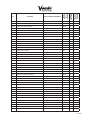
Contents
Page
Safety
S-1 - S-15
Commitment to Safety ..................................................................................S-2
Vendor Installation ........................................................................................S-3
Electrical Hazards .........................................................................................S-6
Mechanical Hazards .....................................................................................S-8
Refrigeration Hazards ...................................................................................S-9
Temperature Hazards ...................................................................................S-9
Substitutions and Modifications ....................................................................S-10
Consumer Safety Warning ............................................................................S-12
Parts, Sales, and Service Centers ................................................................S-13
Parts, Sales, and Service Centers for Latin America ....................................S-14
General Information
G-1 - G-9
Introduction ...................................................................................................G-2
Machine Specifications .................................................................................G-2
Principle Operation .......................................................................................G-3
Start Up .........................................................................................................G-3
Purchase Product .........................................................................................G-4
Installation Requirements .............................................................................G-4
Filling Operation ............................................................................................G-5
Price Label Layout ........................................................................................G-6
Routine Maintenance ....................................................................................G-7
Troubleshooting ............................................................................................G-8
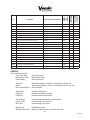
Control Board Programming
P-1 - P-18
Overview .......................................................................................................P-2
Programming Guide ......................................................................................P-2
Sales Mode ..............................................................................................P-2
Service Mode ...........................................................................................P-2
Setup/tbe Ctl ............................................................................................P-3
Set Price ..................................................................................................P-4
Machine Test............................................................................................P-5
Displaying MIS/ERROR Information ........................................................P-7
Entry Code/Password ..............................................................................P-8
Space to Sales (STS) For The Hot Buttons .............................................P-8
Display Programming ..............................................................................P-8
Machine Resets .......................................................................................P-9
Set Time Functions ..................................................................................P-10
Set MIS Access .......................................................................................P-14
Set Motor Pairing .....................................................................................P-15
Internal Diagnostics ......................................................................................P-16
Sales Mode Overview ...................................................................................P-16
Service Mode Overview ................................................................................P-17
Fault Finding
FF-1 - FF-3
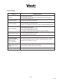
Fault Finding Table ........................................................................................FF-2
ii
08/2005
Maintenance
M-1 - M-4
Chiller Removal .............................................................................................M-2
Power Box Removal .....................................................................................M-2
Tray Removal ................................................................................................M-2
Lock Change/Replacement ...........................................................................M-2
Control Board Replacement ..........................................................................M-2
Motor Replacement .......................................................................................M-2
Vend Hopper Replacement ...........................................................................M-3
Appendix A - Configurable Settings and Defaults........................................ A-1 - A-3
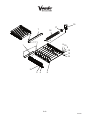
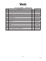
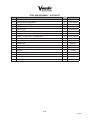
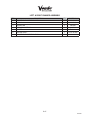
Appendix B - Parts Drawings and Descriptions ........................................... B-1 - B-36
Appendix C - Mis/History/Error Storage ........................................................ C-1 - C-4
Appendix D - Electrical Wiring Diagram ........................................................ D-1 - D-2
iii
08/2005
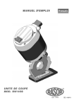
Glass Front Snack Vendor
VS 411 and VSR 411
SAFETY SECTION
S-1
08/2005
A COMMITMENT TO SAFETY
SandenVendo America, Inc. is committed to safety in every aspect of our product design.
SandenVendo America, Inc. is committed to alerting every user to the possible dangers involved
in improper handling or maintenance of our equipment. The servicing of any electrical or
mechanical device involves potential hazards, both to those servicing the equipment and to users
of the equipment. These hazards can arise because of improper maintenance techniques. The
purpose of this manual is to alert everyone servicing SandenVendo America, Inc. equipment of
potentially hazardous areas, and to provide basic safety guidelines for proper maintenance.
This manual contains various warnings that should be carefully read to minimize the risk of
personal injury to service personnel. This manual also contains service information to insure
that proper methods are followed to avoid damaging the vendor or making it unsafe. It is also
important to understand these warnings are not exhaustive. SandenVendo America, Inc. could
not possibly know, evaluate, or advise of all of the conceivable ways in which service might be
done. Nor can SandenVendo America, Inc. predict all of the possible hazardous results. The
safety precautions outlined in this manual provide the basis for an effective safety program. Use
these precautions, along with the service manual, when installing or servicing the vendor.
We strongly recommend a similar commitment to safety by every servicing organization. Only
properly-trained personnel should have access to the interior of the machine. This
will minimize the potential hazards that are inherent in electrical and mechanical devices.
SandenVendo America, Inc. has no control over the machine once it leaves the premises. It is
the owner or lessor’s responsibility to maintain the vendor in a safe condition. See Section I of
this manual for proper installation procedures and refer to the appropriate service manual for
recommended maintenance procedures. If you have any questions, please contact the Technical
Services Department of the SandenVendo America, Inc. office nearest you.
SAFETY RULES
•
•
•
•
•
•
•
•
•
Read the Safety Manual before installation or service.
Test for proper grounding before installing to reduce the risk of electrical shock and fire.
Disconnect power cord from wall outlet before servicing or clearing product jams. The
vending mechanism can trap and pinch hands.
Use only fully-trained service technicians for Power- On servicing.
Remove any product prior to moving a vendor.
Use adequate equipment when moving a vendor.
Always wear eye protection, and protect your hands, face, and body when working near the
refrigeration system.
Use only authorized replacement parts.
Be aware of inherent dangers in rocking or tipping a vending machine.
S-2
08/2005
SECTION I: VENDOR INSTALLATION
A.
Vendors are large, bulky machines of significant size and weight. Improper handling
can result in injury. When moving a vendor, carefully plan the route to be taken and the
people and equipment required to accomplish the task safely.
B.
Remove all tape, shipping sealant, and Styrofoam from the vendor. Loosen any shipping
devices used to secure interior parts during shipping. Remove the wooden shipping base
attached to the vendor base by the vendor leveling screws. Make certain the leveling
screws are in place and functional.
C.
Position the vendor 5.9 inches (15 cm) from a well-constructed wall (of a building or
otherwise) on a flat, smooth surface.
IMPORTANT: The vendor requires 5.9 inches (15 cm) of air space from the wall to
ensure proper air circulation to cool the refrigeration unit.
D.
Adjust the leveling screws to compensate for any irregularities on the floor surface. Ideally,
no adjustment will be necessary and the leveling legs will be flush with the bottom of the
vendor. A spirit level is a useful aid to level the vendor. When the outer door is open, it
will remain stationary if the vendor is properly leveled. Vendors must be level to ensure
proper operation and to maintain stability characteristics. Do not add legs to the vendor.
The leveling legs shall not raise the vendor more than 1 1/8 inch (2.5 cm) above the
ground.
E.
Check the manufacturer’s nameplate on the left or right side of the vendor’s outer door to
verify the main power supply requirements of the vendor. Be sure the main power supply
matches the requirements of the vendor. To ensure safe operation, plug the vendor only
into a properly grounded outlet.
DO NOT USE EXTENSION CORDS.
F.
Recommended voltage specs = volts required + amps of circuit.
NOTE:
Any power supply variance more than + 10% may cause the vendor to malfunction.
*
Power outlets must be properly grounded.
*
Power outlets must be properly polarized, where applicable.
Test the outlets using the following information.
(Refer to Figure 1 on Page S-4.)
S-3
08/2005
S-4
08/2005
SECTION I: VENDOR INSTALLATION (CONTINUED)
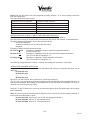
For Type 1 and Type 2 outlets, test for Grounding and Polarization as follows:
1.
With a test device (volt meter or test light), connect one probe to the receptacle’s
neutral contact and the other to the live contact. The test device should show a
reaction.
2.
Connect one probe to the receptacle’s earth contact and the other to the live
contact. The test device should show a reaction.
For Type 3 through Type 5 outlets, test for Grounding as follows:
1.
2.
With a test device (volt meter or test light), determine which of the receptacle’s
power contacts is the live contact.
A.
Connect one probe to the receptacle’s earth contact.
B.
Connect the second probe to the left (or upper) power contact. If a
reaction occurs, this is the live power contact. If a reaction does not occur,
move the second probe to the right (or lower) contact. A reaction should
occur, indicating that this is the live power contact.
Connect one probe to the receptacle’s live power contact (as determined in step
1). Connect the second probe to the other power contact (neutral). The test
device should show a reaction.
IF THE ABOVE CONDITIONS ARE NOT MET FOR THE GIVEN OUTLET
TYPE, CONTACT A LICENSED ELECTRICIAN AND HAVE THE
NECESSARY CORRECTIONS MADE.
S-5
08/2005
SECTION II: ELECTRICAL HAZARDS
GENERAL
SandenVendo America, Inc. vending machines are provided with the appropriate power
supply setting for your area. Some models are equipped with step-down transformers, as
required. This enables the vending machine to operate on different main voltages. Refer
to Section I. E. for information to determine the main power requirements. Refer to the
appropriate service manual for details of step-down transformer operations.
The power sources just mentioned are standard for both household and commercial
lighting and appliances. However, careless or improper handling of electrical circuits
can result in injury or death. Anyone installing, repairing, loading, opening, or otherwise
servicing a vending machine should be alerted to this point. Apply all of the normal
precautions observed in handling electrical circuits, such as:
•
•
•
•
•
•
A.
Refrigeration servicing to be performed by qualified personnel only.
Unplug the vendor or move power switch to off position before servicing or clearing
product jams.
Replace electrical cords if there is any evidence of fraying or other damage.
Keep all protective covers and ground wires in place.
Plug equipment into outlets that are properly grounded and polarized (where
applicable), and protected with fuses or circuit breakers.
All electrical connections must be dry and free of moisture before applying power.
Grounding Systems
SandenVendo America, Inc. vending machines are provided with the appropriate
service cord for the power supply in your area. The service cord will connect to
the matching electrical outlet. Always ensure that the outlet to be used is properly
grounded before plugging in the vendor. (See pages S-3 through S-5.)
WARNING
ALWAYS TEST TO VERIFY PROPER GROUNDING PRIOR TO
INSTALLATION TO REDUCE THE RISK OF ELECTRICAL
SHOCK AND FIRE
The electrical grounding system also includes the bonding of all metal components
within the vendor. This involves a system of bonding wires identified by green or green
and yellow marking. The system uses serrated head screws, lock washers, and star
washers to ensure the electrical connection between parts. Maintenance of vending
equipment may involve disassembly. Include the above items when reassembling, even
if the vending machine may appear to function normally without them. Omitting any
of these items can compromise a link in the grounding system. See the appropriate
service manual or kit instructions for components and assembly instructions.
S-6
08/2005
SECTION II: ELECTRICAL HAZARDS (CONTINUED)
B.
Servicing with “Power Off”
For maximum safety, unplug the service cord from the wall outlet before opening
the vendor door. This will remove power from the equipment and avoid electrical
and mechanical hazards. Service personnel should remain aware of possible
hazards from hot components even though electrical power is off. See the
appropriate sections of this manual for further information.
C.
Servicing with “Power On”
Some service situations may require access with the power on. Power on servicing
should be performed only by fully-qualified service technicians. Particular
caution is required in servicing assemblies that combine electrical power and
mechanical movement. Sudden movement (to escape mechanical action) can
result in contact with live circuits and vice versa. It is therefore doubly important
to maintain maximum clearances from both moving parts and live circuits when
servicing.
WARNING
“POWER ON” SERVICING SHOULD BE ACCOMPLISHED ONLY BY
FULLY-TRAINED PERSONNEL. SUCH SERVICE BY UNQUALIFIED
INDIVIDUALS CAN BE DANGEROUS.
Power to lighting and refrigeration system is shut off automatically by the electronic
controller when the outer door is opened.
NOTE:
For power-on servicing of the vendor’s lighting system, turn lighting power
on by accessing the Lights test function of the electronic controller (see
programming on inner door).
For power-on servicing of the vendor’s refrigeration system, turn refrigeration
power on by accessing the Compressor test function of the electronic
controller (see programming on inner door).
S-7
08/2005
SECTION III: MECHANICAL HAZARDS
A.
Servicing of Moving Parts and Assemblies
When servicing assemblies involving moving parts, use extreme caution!!
Keep fingers, hands, loose clothing, hair, tools, or any foreign material clear of
entrapment.
As noted before under the electrical hazards section, Power On servicing should
only be performed by qualified personnel. Refer to and heed the warnings noted
in the electrical hazards section. These warnings refer to the potential hazards
associated with electrical power and moving parts. Always maintain maximum
clearances from electrical and moving parts.
Always install protective covers and guards when reassembling equipment.
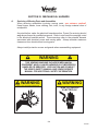
WARNING
THIS VENDING MACHINE INCLUDES MECHANICAL
EQUIPMENT WHICH CAN BE HAZARDOUS IF IMPROPERLY
HANDLED OR SERVICED. USE CAUTION AND CONSULT
THE VENDO SAFETY MANUAL AND VENDO SERVICE
MANUAL FOR ADDITIONAL SAFETY INFORMATION.
WARNING
WARNING
RISK OF ENTRAPMENT!
RISK OF SHOCK!
ELECTRICAL!
S-8
08/2005
SECTION IV: REFRIGERATION HAZARDS
GENERAL
Refrigeration systems involve both electrical power and mechanical action. These
systems may present any of the potential dangers shown in the sections on electrical
and mechanical hazards contained in this manual. See Sections II and III for further
information.
A.
Compressed Refrigerant
Refrigeration systems involve the compression and evaporation of gases. The
pressures contained represent a potential hazard if suddenly released in confined
areas. Caution is required when performing maintenance tests or repairs. All
testing of sealed refrigeration systems must be done by trained personnel who are
familiar with the systems and pressures involved.
B.
Physical Protection
The accidental release of refrigerant gases can result in physical injuries. Always
wear protective glasses and protect your hands, face, and body when working
near the refrigeration system.
WARNING
ALWAYS WEAR EYE PROTECTION AND PROTECT YOUR
HANDS, FACE, AND BODY WHEN WORKING NEAR
THE REFRIGERATION SYSTEM
SECTION V: TEMPERATURE HAZARDS
GENERAL
Maintenance personnel should be alerted to the potential hazards from hot metal
surfaces. High temperatures may be present throughout the refrigeration system even
though electrical power has been removed.
S-9
08/2005
SECTION VI: SUBSTITUTIONS AND MODIFICATIONS
GENERAL
Unauthorized changes or the substitution of unauthorized parts can compromise the
equipment designs. This can result in unsafe conditions for either the service personnel
or the equipment users. Always refer to the appropriate parts and service manual for
replacement parts and maintenance instructions. If questions arise, contact the Technical
Services Department of the SandenVendo America, Inc. office in your area.
When servicing the vending machine, always reassemble all components to their original
location and position. Maintain the correct routing for tubing, electrical wiring, etc..
Replace all clamps, brackets, and guides to their original locations. Replace all tubing,
sleeving, insulating material, and protective covers to their original condition
WARNING
VENDO EQUIPMENT HAS BEEN PROVIDED WITH APPROPRIATE PROTECTIVE
DEVICES TO PROTECT AGAINST THE POSSIBILITY OF OVERHEATING AND
FIRE AS A RESULT OF EQUIPMENT OR COMPONENT FAILURES.
SUBSTITUTION, MODIFICATION, OR BYPASSING OF SUCH PROTECTIVE
DEVICES CAN CREATE DANGEROUS CONDITIONS. PROTECTIVE CIRCUITS
SHOULD NEVER BE BYPASSED, AND FAILED PROTECTIVE DEVICES MUST
BE REPLACED ONLY WITH FACTORY-AUTHORIZED PARTS.
A.
Service Cord Replacement
SandenVendo America, Inc. vending machines are furnished with unique power
supply cords. If replacement becomes necessary, consult the appropriate parts
and service manual and order the correct replacement cord for the model of
vending machine in question. Do not use substitute replacement cords. Only
authorized service personnel with appropriate training should replace the vending
machine service cord. If a question should arise concerning which service cord to
order, contact the Technical Services Department of the SandenVendo America,
Inc. office in your area.
S-10
08/2005
SECTION VI: SUBSTITUTIONS AND MODIFICATIONS (CONTINUED)
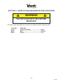
WARNING
THIS APPLIANCE MUST BE EARTHED.
IMPORTANT!
The wires in the main leads are colored in accordance with the following code:
110v/120v
Green
White
Black
220v/240v
Green and Yellow ............................. Earth
Blue ................................................... Neutral
Brown................................................ Live
S-11
08/2005
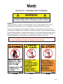
SECTION VII: CONSUMER SAFETY WARNING
WARNING
VENDOR CAN BE OVERTURNED IF SUFFICIENT FORCE IS
APPLIED AND MAY RESULT IN SERIOUS INJURY OR DEATH.
GENERAL
There have been incidents, including fatalities, when vending machines have been
vandalized by being pulled over in an attempt to obtain free product or money.
To warn of the danger involved in tipping, shaking, or rocking the vending machine, a
decal has been designed to be affixed to vending machines. (One such decal is applied
on the vending machine.) SandenVendo America, Inc. will supply sufficient decals to be
placed on all machines, on request. If you have any questions, contact the Technical
Services Department of the SandenVendo America, Inc. office in your area.
THE FOLLOWING DECAL SHOULD BE PLACED IN A POSITION
ON THE VENDOR CONTROL PANEL AT EYE LEVEL
S-12
08/2005
SECTION VIII: PARTS, SALES, & SERVICE CENTERS
OF SANDEN COMPANY
AREA
United States,
Canada
ADDRESS
SandenVendo America, Inc.
10710 Sanden Drive
Dallas, TX 75238-1335 U.S.A.
Japan
Sanden International Corporation
31-7 Taito 1-Chome
Taito-ku
Tokyo 110, Japan
Europe, Mid-East Vendo GMBH
Africa, Mid-Asia Spangerstr. 22, P.O. Box 130940
40599 Dusseldorf
Germany
Australia,
Sanden International Pty. Ltd.
New Zealand
54 Allingham St., Condell Park
N.S.W. 2200
Australia
Singapore,
Sanden International (Singapore) Pte., Ltd.
Hong Kong,
Sanden House, 25, Ang Mo Kio St. 65
Indonesia,
Singapore 569062
Phillippines, India The Republic of Singapore
Taiwan
Sanden International Taiwan Corp.
No, 21-6, Sec 1
Tun Hwa S. Rd., Taipei, Taiwan
Taiwan, ROC
Belgium
N.V. Vendo Benelux, S.A.
Industrial Research Park N.O.H.
13 Font St. Landry
1120 Brussels
Belgium
England
Vendo UK Ltd.
Vendo House
Kingsclere Road
Basingstoke, Hants RG21, 5GU
Great Britain
Italy
Vendo Italy S.p.A.
Casella Postale 9
1-15033 Casale Monferrato
Italy
Spain
Vendo Iberia, S.A.
C/ Sant Ferran No. 92
Poligono Industrial la Almeda, Sector P-1
08940 Cornella, (Barcelona), Spain
S-13
PHONE NUMBERS
Tel: (800) 344-7216 ext.
3368
Fax: (800) 541-5684
Tel: (81) 3-3835-1321
Fax: (81) 3-3833-7096
Tel: (49) 211-74-039-0
Fax: (49) 211-7488541
Tel: 61-2-9791-0999
Fax: 61-2-9791-9029
Tel:
Fax:
65-482-5500
65-482-1697
Tel: 886-2-570-6106
Fax: 886-2-577-1959
Tel: 32-2-268-2595
Fax: 32-2-268-2862
Tel: 44-1256-479309
Fax: 44-1256-844469
Tel: 39-142-335111
Fax: 39-142-5623-48
Tel: 343-474-1555
Fax: 343-474-1842
08/2005
SECTION IX: PARTS, SALES, & SERVICE CENTERS OF
SANDEN COMPANY FOR LATIN AMERICA
AREA
Mexico
Central America
Chile
Brazil
South America
ADDRESS
Vendo de Mexico
Camino Real de Toluca No. 154
Col. Bellavista
01140 Mexico D.F. Mexico
SandenVendo America, Inc.
10710 Sanden Drive
Dallas, TX 75238-1335 U.S.A.
Pelp Internacional, S.A.
4560 El Rosal
Huechuraba, Santiago, Chile
Cimaq Industria e Comercio de Maq, Ltda.
Estrada Uniao e Industria, 9.120 Itaipava
25730-730 Petropolis
Rio de Janeiro, Brazil
SandenVendo America, Inc.
10710 Sanden Drive
Dallas, TX 75238-1335 U.S.A.
S-14
PHONE NUMBERS
Tel: (525) 515-9745
Fax: (525) 277-0111
Tel: (800) 344-7216 ext.
3368
Fax: (800) 541-5684
Tel: (562) 243-9710
Fax: (562) 740-0504
Tel: (55242) 22-2666
Fax: (55242) 22-3244
Tel: (800) 344-7216 ext.
3368
Fax: (800) 541-5684
08/2005
NOTES
S-15
08/2005
Glass Front Snack Vendor
VS 411 and VSR 411
GENERAL INFORMATION
SECTION
G-1
08/2005
General information
1.0 Introduction
This service manual covers the VS411 and the VSR411 Snack Vending Machine.
This manual is designed to act as a reference for service technicians.
We recommend that you study this manual as there are many features and uses.
If you do not understand any part of this manual please contact The SandenVendo
America, Inc. Technical Service Department at (800) 344-7216 ext 3368.
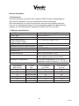
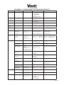
1.1 Machine specifications
Product Name
Product Type
Location Environment
Outside size inch (mm)
(Length x Width x Depth)
Weight lbs (kg)
Adjustment scope for screw inch (mm)
Voltage (v)
Frequency (Hz)
Nominal current (A)
Product capacity
Refrigeration Temperature
Tray position
(Black Color)
A
B
C
D
E
F
Glass Front Snack Vending Machine
VS-411 & VSR-411
Inside only
72 x 37 x 28 (1830 x 940 x 720)
Net weight 661.35 (300)
.79 (20)
115 +10%/-15%
60
VS-411 (0.6) & VSR-411 (8.5)
Followed by owner’s needs (note: for normal
product capacity, please see list below)
Environment Temperature ≤ 104°F (40°C),
Temperature Inside of machine ≤ 77°F (25°C)
Product
tray
4 product tray
4 product tray
8 product tray
8 product tray
8 product tray
8 product tray
# of Products
per Chute
8
10
10
12
14
18
G-2
# of Products
per Tray
32
40
80
96
112
144
08/2005
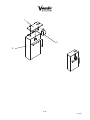
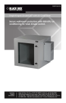
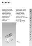
Instruction Window
LCD
Glass
Keypad
Door Lock
Coin Return Button
Coin Entry
Vend Hopper
Coin Return Door
1.2 Principle operation
When coins or bills are inserted, the identification system will identify the bills and coins;
then the amount of money will appear in the LCD window. Press the key pad to choose
the goods you want to purchase. Then machine will drive the selected products to the
vend hopper. If there is still some change left, you can continue purchasing. If you don’t
want to purchase anything more, press the coin return button to get the change. If no
other products are selected within a 30 second period, the change will be automatically
returned.
1.3 Startup
1. Open the door of the machine, connect the power, and turn on the power switch.
2. Fill coin mechanism with change.
3. Fill all the products into the trays one by one (See 1.7 Filling Operation).
4. Install the price label (See 1.8 Price Label Layout).
5. Set up the machine control system as per the customers’ requirements (See the
Programing Section of the manual).
6. Lock the door of the vending machine. The vending machine is ready for use.
G-3
08/2005
1.4 Purchase Product
$
$
1. Insert Money
C
B
A
D
1
4
7
E
2
5
8
F
3
6
9
#
0
*
2. Choose Product
3. Coin Return
4. Take Out Change
5. Remove Product
Diagram 1
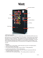
1.5 Installation Requirements
1.5.1 Ensure the machine is level, and adjust the screws on the feet as below (diagram
2). A level machine will ensure that the door automatically stays in any position
when it is open.
4
1
3
2
Diagram 2
G-4
08/2005
1.5.2 Make sure the machine has enough space in the front and at the door axis side to
let the door open enough.
1.5.3 The distance between the wall and the back of the vending machine should be
more than 15cm (5.9 inches) to ensure a good air flow, otherwise the function of
chiller will be affected and may not work properly.
1.5.4 Put the machine on flat and stable ground. Prevent water splash on the
machine and avoid leakage that may harm people after raining. Keep away from
heat source. Avoid direct sun light and put in a place where there is good air
conditioning.
1.5.5 The power supply must be 115V/60Hz and the rated supply current should be
more than 16A. The ground wire must connect with ground to prevent shock,
and to prevent electromagnetic interference caused by static electricity. All wire
connections must be made by a professional electrician.
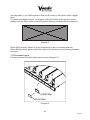
1.6 Filling Operation
Open the door to the maximum position. Lift up the tray approximately 30mm (1.18
inch), and then pull it out to the stop position. There should be only one tray in the filling
products position at a time. When pushing the tray back, it must be pushed back to the
original position as shown in (diagram 3).
3
1
2
4
Diagram 3
When filling products, don’t force them into the spiral. Products should be put in freely.
If there is not enough space for it to move, it will get jammed, and the consumer won’t
G-5
08/2005
get the product. If you find the product does not fit loosely in the spriral, select a bigger
spiral.
For plastic packaged products, we suggest folding the bottom of the product, before
putting it into the tray in order to prevent product jamming as shown below (diagram 4).
Diagram 4
When filling products, please try to put all products to lean in the same direction.
When filling products, please notice the height of the product to avoid jamming between
two trays.
1.7 Price Label Layout
Put the price label into shelf strip insert as shown (diagram 5).
A4
1.0
0
A5
1.0
0
A6
1.0
0
A7
1.0
0
A8
1.0
0
Shelf Strip
Price Label
Diagram 5
G-6
08/2005
1.8 Routine Maintenance
1.8.1 Use soft cloth dipped in detergent to clean the bill entry chute. This will help to
prevent dust from affecting the bill identification mechanism.
1.8.2 Use soft cloth dipped in detergent to clean the coin entry chute. This will help to
prevent coins from sticking on the chute affecting the normal working process.
1.8.3 Ensure the tray, vend hopper, and key pad are clean.
1.8.4 Once the power is connected, do not remove the plug, otherwise data will be lost
and it will even damage other electric components.
1.8.5 Do not place goods around the evaporator in the cabinet, as this will affect the
function of the chiller and cause problems.
1.8.6 Liquids are to be prohibited from contacting the electrical parts and the
mechanism on the Bill Validator or Coin Mechanism.
1.8.7 Use soft cloth dipped in detergent to clean the glass and the surface of the
machine.
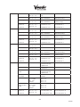
1.9 Troubleshooting
Problem
Reasons
Solution
Does not
accept bills
1. Changer out of change
2. Foreign material inside of Bill Validator
3. Money is incorrect
4. Plugs are loose
5. Bill Validator is damaged
1. Correctly fill up coins
2. Clean the Bill Validator
3. Use correct money
4. Reinstall the connector after turning off the power
5. Change to a new one
Does not
accept coins
1. Change is incorrect
2. Indicator of Coin Mechanism (CM) is
not working
3. Coin jam or dust in the CM
4. Jam on electromagnetic distribution
brake
5. Indicator of CM is designating an error
6. Water got into CM
7. CM damaged
1. False coin can not be accepted, use correct
currency
2. Check if the power and plug are loose
3. Open up the machine to clean CM
4. Use small tool to remove the jammed components
5. Check low level transducer, use Alpha to delete all
the faults by adjusting 349 address to 1
6. Take out the CM ,use dryer to dry it
7. Change to a new one
1. Coins incorrectly filled
2. Control board didn’t adjust into the
correct position for returning change
3. Coin return pole of CM got jam
4. The address of the CM is not correct
5. Label price and setting price are not
matched
6. CM is damaged
7. Coin return mechanism is in the wrong
position
1. After resetting, fill coins correctly
2. Adjust into the correct change status otherwise no
change will return or less change will return.
3. Check the part that got jammed. Check the
reposition status of each coin return pole, (press
button MODE twice, each pole returns to front
automatically)
4. Adjust each position or change
5. Reset price carefully to match
6. Change to a new one
7. Check and correct the coin return mechanism
position
1. Spiral jamming
2. Spiral didn’t return to the same position
3. Mistakingly chose the empty chute
4. Incorrect product filling
1. Cleanup and reposition it to let the motor turn one
cycle
2. Take out the spiral to adjust it to the original
position
3. Adjust the price of empty chute to “0” or the highest
price or fill the chute
4. Choose correct products for the spiral. If the
dimension of the products is smaller than 2/3 of the
spiral diameter, they will cause a jam
Incorrect
change given
Correct change
given, but no
product was
given
G-7
08/2005
Products in the
chute,
but does not
sell
1. The price of product is higher than the
inserted money
2. Vend motor failure
1. Air flow hatch got jammed
Refrigeration
Compressor has 2. The position of thermostat is not correct
no
3. Low on refrigerant
refrigerating
effect
The door can
not be locked
Products
continue to go
out
1. Continue to insert money until it is enough or more
than the product price
2. Test motor by swapping motor connection with
another motor. If that motor works, replace the
defective motor.
1. Clean it up, position the rear of the machine 15cm
(5.9 inch) from the wall.
2. Adjust the controller into the right position
3. Find professional refrigeration maintenance person
to replace or add refrigerant.
1. The machine is not leveled.
2. The distance between Lock and Lock
socket is long.
1. Level the machine, adjust the screw under the lock
one pitch lower than other three screws
2. Loosen the door lock mounting nut, adjusting it up
and down until you can close the door easily
1. Selling products mechanism has
problems
1. Check the motor position switch whether it works
normally, if it works normally, then it is the control
board’s problem, change to a new one.
G-8
08/2005
NOTES
G-9
08/2005
Glass Front Snack Vendor
VS 411 and VSR 411
PROGRAMMING SECTION
P-1
08/2005
Control Board Programming
1.0 Overview
The Vending Machine Controller (VMC) fitted to the 411VS & 411VSR is known as the MCB560. This is
similar in design and operation to the unit fitted to the MARS SERIES 2000 BRANDED VENDOR (MDB
board interface).
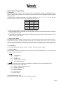
A maximum of 60 selections are made via a matrixed keypad ("A" – "F", "1" – "9", "*", "0", "#"), where a
product selection is made by pressing one letter and one numeric key.
A
D
1
4
7
*
B
E
2
5
8
0
C
F
3
6
9
#
The VMC may be programmed using one of the following methods
1) Manual programming is performed with the door open using the mode switch (located on the VMC)
and the selection switches.
2) Automated programming is performed by uploading configuration and/or price information from the
DEX/UCS hard wired interface.
1.1 Programming Guide
All programming is performed using the selection keypad. The board provides two interface modes - sales and service.
Sales mode is accesed by pressing and holding the door switch for 5 seconds when the door is open. The service
mode is accessed by pressing the mode switch on the VMC (the door must remain open while in service mode). Once
in service mode the "#" key is used to scroll through the service modes. The available service modes are listed below.
1.1.1 Sales Mode
Once in Sales Mode, total sales per machine, per shelf, or per spiral can be viewed.
1.1.2 Service Mode
In Servie Mode, press the number key to scroll through each mode as indicated below. For an overview of
the Service Mode, see page P-17.
1.1.3
1.1.4
1.1.5
1.1.6
1.1.7
Setup/tube Ctl
Set Price
Machine Test
Mis/history/errors Display
Entry Code/password
Additionally, Engineer service modes are accessible by entering the correct 4 digit password. The
additional service modes are listed below.
1.1.8 Space To Sales (Sts) Programming
1.1.9 Display Programming
1.1.10 Machine Resets
1.1.11 Set Time Functions
1.1.12 Set Mis Access
1.1.13 Motor Pairing
The default password is “3142”.
Appendix 1 lists all VMC parameters, and their default settings.
P-2
08/2005
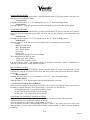
1.1.3 Setup/tube Ctl (Service Mode 1)
This mode is first accessed when the VMC mode switch is pressed.
This service mode is used to perform the following actions:
Configure the machine
Dispense coins
Select the type of coin mech used
Display the coin tube inventory
Setup the overpay feature
Set/clear the vend detector present flag
Each of these options is set by repeated presses of the same button.
Button
A
B
D, E,
1, 2
7
8
*
0
Option
Cash Handling
Change Handling
Coin dispense (MDB only)
Coin tube inventory display
Single/multi price
Set overpay value
Vend detect sensor fitted
BUTTON “A”, CASH HANDLING
Pressing button "A" will display the present mode of cash handling. Repeated presses of the button scrolls
through the different types of cash handling.
CASH HANDLING
Force Vend
Force Bill/Coin
Change Machine
DESCRIPTION
No escrow return unless a selected product is sold out.
If a bill is stacked or a non tubed coin is accepted, then a selection must be
made.
Bills are always stacked. Escrow Return always returns the credit.
Neutral
Except that the first bill is held in escrow, the mode is the same as “Change
Machine”
No Change
Change is never paid out. The machine operates with a bill acceptor only or
with a tubeless coin mech.
BUTTON “B”, CHANGE HANDLING
Pressing button "B" will display the present mode of Change Handling (Multi/Normal Vend). Continued
presses of the button, toggles between the different types of change handling.
CHANGE HANDLING
MODE
Normal Vend
Multivend
DESCRIPTION
Change is paid out after the VMC detects the delivery of product (if the Vend
Detect beam is used) or after the motor leaves home (no Vend Detection
used)
If the remaining credit (after a vend) is >= to the minimum Vend price, the
credit will not automatically be returned at the end of the vend. A customer
can add additional credit, buy another product, or retrieve the credit. The
credit is automaticly returned after 20 seconds.
P-3
08/2005
BUTTONS “D”, “E”, “1”, and “2”, COIN DISPENSE
The VMC recognises the selections "D", "E", "1", and "2" as dispense switches for a 3 or 4 tube MDB coin
mech.
SWITCH
DESCRIPTION
Dispenses coins from the tube associated with the 1st/lowest value coin
Dispenses coins from the tube associated with the 2nd coin
Dispenses coins from the tube associated with the 3rd coin
Dispenses coins from the tube associated with the 4tht/highest value
2
tubed coin
If the tube inventory mode is activated (via button "7"), these switches are still active.
If an Executive mech is used, then these switches have no function.
D
E
1
BUTTON “7”, COIN TUBE INVENTORY DISPLAY
Pressing button "7" will cause the display to show the last known value of the coin mech tube inventory
("Inv xxx.xx"). Depositing coins will increase the value and dispensing coins will decrease the value. This
status is only available with MDB coin mechs (when an Executive mech is attached, the display will show
"Inv 000.00").
BUTTON "8", SINGLE/MULTI PRICE SELECTION
Pressing button "8" will display the present configuration of the machine (single vs.multi price). Continued
presses of the button toggles between the two different modes.
DISPLAYED MODE
DESCRIPTION
Single Price
All items are sold at the price assigned to selection A1. Note, the prices of the
other selections A2 – F0 are not cleared or reset to the price of selection A1.
Multi Price
All items are sold at the prices specified for each selection.
BUTTON “*”, INC/DEC THE OVERPAY VALUE
When button "*" is first pressed, the machine will display: Overpay xx.xx
Where xx.xx is the max overpay amount. While the above message is displayed, pressing and holding
selection switch "*" will increase the amount of overpay. Pressing and holding the switch a second time will
decrease the amount.
BUTTON "0", VEND DETECT IS PRESENT
Pressing the button "0" will display the present configuration of the machine (Vend Detect Present, Yes vs.
No). Continued presses of the button toggles between the two different modes.
DISPLAYED MODE
DESCRIPTION
Vend Detect Yes
The Vend Detect hardware is present in the machine.
Vend Detect No
The Vend Detect hardware is not present in the machine.
The standard machine does not have vend detect technology fitted.
1.1.4 Set Price (Service Mode 2)
Pressing the "#" button once while in the service mode accesses this function. The display will show "Set
Price". There are two options within this service mode, Viewing Prices or Setting Prices.
Viewing Prices
When the display shows "Set Price", the pressing of an alpha button ("A"-"F"), sets
the VMC into price viewing mode. The display will show
View A_ XXX.XX (Assuming "A" was pressed)
View A1 XX.XX (Assuming "1" was pressed)
Where XX.XX is the price currently set.
P-4
08/2005
Setting Prices
If the display is showing “Set Price", or "View XX.XX", the pressing of a numeric button ("0"-"9") sets the
VMC into price setting mode. The display will show
Set __ 000.0x (Where x is the numeric pressed)
The pressing of numeric buttons will introduce numbers to the right hand side, and the existing numbers
will be shifted left. When the required price is displayed the pressing of an alpha button will freeze the price.
The alpha character is interpreted as the first key in the spiral identification (e.g. "A1"). If the price is set to
60p and "A" pressed the display will show
Set A_ 0.60
Pressing a numeric key will assign this price to a selection. The price is confirmed by pressing the “#” key
and the machine then goes to the next service mode. If the "*" button is pressed, this assigns the price to
the entire shelf (e.g. Set C* 0.50, will assign a price of 0.50 to all selections on tray C).
If another selection button sequence (e.g. "A3", "B4", "F7") is entered, the VMC will assign the displayed
price to that selection.
If a numeric button is pressed when the VMC is expecting an alpha key, the VMC will assume that the price
is being changed, and allow numeric values to be entered.
If two alpha buttons are pressed (e.g. AA), the VMC will return to View mode.
Notes on Prices
The maximum price available is 65000 times the scaling factor when using MDB interface. When using the
Exec interface the maximum price is 250 base units. When in PRICE HOLDING/PRICE DISPLAY mode,
the range of price lines is 1 to 10.
When neither a coin mech or debit card reader is present prices can only be set in increments of 0.05.
When either a coin mech and/or debit card reader is present, prices can be set in increments of the lowest
scaling factor.
If a price is entered that is NOT an increment of the lowest scaling factor the VMC will round down the price.
Pre-configured (Reset) price is 650.00. If you accidently press an incorrect number when setting the price,
continue pressing the “0” key until the digit spaces can be reset by you to the correct price.
1.1.5 Machine Test (Service Mode 3).
It is possible to test a range of machine functions. Some require additional hardware to be used. The
functions that can be tested are
Vend Motors
Vend Detector
Keypad Buttons
Touch Interface
DEX Interface
Pressing the "#" button twice while in the service mode accesses this function. The display will show
"Machine Test". The button functions are as follows:
A – Test Motor, increment letter
D – Test Motor, run motor
1 – Activate Switch Test
4 – Activate DEX Test
7 – Motor Scan Start/Continue
* - Stop Test
B – Test Motor, increment number
E – Activate Beam Test
2 – Activate Touch Test
5 – N/A
8 – Motor Scan Skip/Continue
0 – Stop Test
P-5
08/2005
Test Vend Motor
While in Machine Test mode, pressing buttons "A", "B" or "D" will display "Test Motor A1", and the machine
will enter the test motor mode. Button "A" is used to increment the alpha character, and button "B" increments
the numerical value. Pressing button "D" runs the motor.
When button "D" is pressed the VMC will attempt to run the selected motor. The possible messages during
the motor test are:
A1 Running Indicates the motor is running
A1 Low Current Indicates the motor failed due to low current
A1 High Current Indicates that a high level of current was detected
A1 Stuck Home Indicates that the motor never left home
A1 Time Out Indicates that the motor did not return to home
A1 Motor Ok Indicates the motor completed the test vend successfully
The motor test mode is exited by hitting the mode switch or buttons "*" or "0".
Test Vend Detect.
This has not been implemented on the initial machine production. The information below is therefore only
a proposed implementation.
Pressing the "E" will display "Vend Detect Test". A second press of "E" activates the vend detect test. While
the test mode is active the display will show "Beam Ok"
when the detector is in steady state, and then will display "Beam Error" if the detector is disturbed.
The Vend Detect test mode is exited by hitting the mode switch or buttons "*" or "0".
Keypad Test
While the machine is in test mode, pressing button "1" will display "Switch Test". A second press of "1"
activates the test. While the mode is active, the display will show any button which is pressed. Exiting the
test occurs if no button is pressed for 30 seconds.
DEX/UCS Test
While the machine is in test mode, pressing "4" will display "DEX/UCS Test". Pressing "4" a second time
activates the DEX/UCS test mode. While the mode is active, the VMC transmits a test pattern to the DEX/
UCS port. This test message is verified by connecting a loop back cable from the DEX/UCS port to the Exec
port. Possible messages during the test are:
DEX/UCS Test Message when "4" is pressed for the first time
Insert Loop Back Message when VMC is waiting for the loop back to be connected
DEX/UCS Test Passed Message when test passes
DEX/UCS Test Failed Message when test fails
The DEX/UCS test mode is exited by hitting the mode switch or buttons "*" or "0".
Motor Scan Test
While the machine is in test mode, pressing "7" will display "Motor Scan Test". Pressing "7" a second time
activates the Motor Scan test. The VMC will then run each motor in turn and confirms the motors return to
the home position. The VMC will attempt to run all motors. If a motor fault is detected, the test will stop and
the bad motor identified and the problem displayed. Pressing "7" will retest the faulty motor, and pressing
"8" will resume the test on the next motor. Possible messages during the Motor Scan test are
A1 Running Indicates the motor is running
A1 Low Current Indicates the motor failed due to low current
A1 High Current Indicates that a high level of current was detected
A1 Stuck Home Indicates that the motor never left home
A1 Time Out Indicates that the motor did not return to home
A1 Motor Ok Indicates the motor completed the test vend successfully
The motor scan test mode is exited by hitting the mode switch or buttons "*" or "0".
P-6
08/2005
1.1.6 Displaying Mis/error Information (Service Mode 4)
The Display MIS/Error/History Mode is entered when the "#" button is pressed three times. Upon entering
the mode, the display will show "MIS Display". The selection button actions are :
(A) Dec thru Reset. MIS
(D) Dec thru Hist. MIS
(1) Dec thru Event log
(4) Dec thru Error log
(7) Cycles thru Reset type
(*) n/a
(B) Inc thru Reset. MIS
(E) Inc thru Hist. MIS
(2) Inc thru Event log
(5) Inc thru Error log
(8) Displays time/Performs Reset
(0) n/a
MIS DISPLAY
Buttons "A", "B", "D", and "E" are used to view the MIS information. The MIS information is reported in the
DEX/UCS format. The DEX/UCS codes are described in appendix C.
EVENT HISTORY DISPLAY
Buttons "1" and "2" are used to view the Door History, and Exact Change history. Button "8" is used to
display the time/date when the event occurred (the time/date is displayed until another button is pressed).
Door History can not be reset; the display shows the last 2 occurrences of the door being opened. The
"Sold Out" and "Exact Change" events can be reset. If there have not been any events since the last reset,
"None" will be displayed.
Note, that the door has to be closed for 30 seconds before an additional event is logged. The Sold Out
feature only applies to those machines fitted with a vend detector and ‘Hot Buttons’.
Door history is displayed as:
Door Opened Last When the door was last opened.
Door Opened Prev When the door was previously opened.
The Exact Change information is displayed as:
Exact Change Det Indicates that the machine was in the Exact Change State
When button "8" is pressed, the time and date is displayed as:
hh:mm dd/mm/yy dd
Where hh:mm is the time when the event occurred.
Where dd/mm/yy is the date when the event occurred.
Where dd is the duration in hours, for Exact Change.
Pressing button "8" again, takes you back to the event message.
ERROR LOG DISPLAY
Buttons "4" and "5" are used to view the error log. Button "8" is used to display the time/date when the event
occurred (the time/date is displayed until another button depression). The error log can store 20 events (the
last event to occur is the 1st displayed). If the log is empty (due to a reset), "No Errors" is displayed.
The possible error messages are:
Coin Mech
When an MDB coin mech has reported an error
Bill Acceptor
When an MDB bill acc. has reported an error
Card Reader
When an MDB reader has reported an error
Selection x
When selection button "x" (A – F, 1 – 0, *) is bad (e.g. button is closed for > 30 sec)
Motor xx
When motor "xx" (A1 – F8) has gone bad (ran OK during motor scan, but failed
during a vend.)
Door Opened When the door has been left opened > 60min
Touch
When there’s a problem with Touch
DEX
When there’s a problem with DEX
Fraud Detect
When a fraud attempt has been detected (e.g. reported by a card reader, etc.)
Chute Fraud
When a fraud at the chute has been detected
P-7
08/2005
Bill Fraud
When a bill acceptor fraud has been detected (e.g. bill pull)
Battery
When the RAM is corrupted due to the battery
SW Mismatch When the SW rev’s mismatch (uP and Flash)
When button "8" is pressed, the time date is displayed as:
hh:mm dd/mm/yy
Where hh:mm is the time.
Where dd/mm/yy is the date when the event occurred.
Pressing button "8" again, takes you back to the event message.
RESETTING THE MIS/HISTORY/ERROR LOGS
Button "7"cycles through the different types of resets:
Reset MIS
Resets Interval/Resetable fields
Reset Event Log
Resets the Event History log
Reset Error Log
Resets the Error log
Button "8" performs the reset (the switch must be held for 2 seconds).
Note that errors are not auto cleared from the log (e.g. if an error associated with button "4" has been
posted, it will not automatically be removed when button "4" is repaired).
1.1.7 Entry Code/password (Service Mode 5)
The Entry Code Mode is entered when the "#" button is pressed four times. Upon entering the Entry Code
Mode, the display will show "Entry Code".
In order to enter the STS Programming mode or the modes above (modes 7 – 13), an
entry code must be keyed in. If the correct entry code is not keyed in, then a press of the mode switch (or
"#" button) will cause the system to enter normal operation mode. The entry code is entered by pressing
selection buttons "3", "1", "4", and "2", in sequence, followed by a press of the "#" button in order to proceed
to the Space to Sales Programming mode.
Once the correct entry code has been keyed in, it will not need to be keyed in again unless the door is
closed or a five minute service time out has occurred.
1.1.8 Space To Sales (STS) For The Hot Buttons (Service Mode 6)
The STS programming mode is entered when the door is opened and the "#" button is depressed five times.
Upon entering the mode, the display will show "STS Programming". The STS for the 3 Hot buttons can be
viewed, cleared, and modified (motors can be both added and removed).
Note: This feature has not been implemented in the current version of this machine.
Therefore no functionality has been implemented.
1.1.9 Display Programming (Service Mode 7)
The Display Programming Mode is entered when the "#" button is pressed six times. Upon entering the
mode, the display will show "Display Setup".
The selection button actions are:
(A) Selects English or Alt Lang
(D) Dec thru Msg List
(1) Moves cursor left
(4) Dec value at cursor pos.
(7) Insert space
(*) Selects Display Config
(B) Set to English
(E) Inc thru Msg List
(2) Moves cursor right
(5) Inc value at cursor pos.
(8) Delete char at cursor
(0) Selects options for Config
Button “A” selects between the standard English messages and the alternate (programmable/loadable)
messages. The standard English messages can not be modified, only the alternate language messages
can be changed. Note that the alternate messages are loaded via DEX.
P-8
08/2005
Button "B" copies the English messages into the alternate message area. Note, that this button must be
pressed twice (at least 1 second apart, but not more than 5 seconds apart).
Buttons "D", "E", "1", "2", "4", "5", "7" and "8" are used to change the alternate messages.
Buttons "*" and "0" are used to control the information displayed to the user. Button "*" cycles through
5 different parameters, while button "0" cycles through the options associated with the parameters. The
parameters and their options are below:
Append Time to the User Message
Display Time No/12H/24H (no, 12 or 24 hour format)
Append the Block Time to the User Message
Blocker Time No/12H/24H (no, 12 or 24 hour format)
Append Discount Message to the User Message
Discount Yes/No
Display Exact Change State (Append message, etc.)
Exact Chg No/Some/Full
Append Reason to the Out of Order Message
Err Codes Yes/No
Beep for Each Key Depression
Beep Key Yes/No
After a machine reset, the default settings are:
Display Time No
Blocker Time 24H
Discount Yes
Exact Chg Some
Err Codes Yes
Beep Key Yes
1.1.10 Machine Resets (Service Mode 8)
The VMC allows 3 types of Machine Resets (in addition to the MIS interval reset, the error log reset, and
the history event log reset).
Configuration Reset
Total Machine Reset
MIS Historical Reset
The Machine Reset mode is entered when the "#" button is pressed seven times.
Upon entering the mode, the display will show "Machine Reset".
The button functions are given below:
(A) N/A
(D) Moves to Previous Menu
(1) N/A
(4) Decrements the Value
(7) Executes Reset
(*) N/A
(B) N/A
(E) Moves to the Next Menu
(2) N/A
(5) Increments the Value
(8) Executes Reset
(0) N/A
P-9
08/2005
CONFIGURATION RESET
Once the display shows "Machine Resets", pressing selection button "E" will move control to the next menu
level, where the machine will display:
Config Reset N
Pressing selection button "4" or "5" will change the "N" to a "Y". Once the display shows:
Config Reset Y
Pressing buttons "7" or "8" will cause the machine’s configuration to be reset to the default values.
TOTAL MACHINE RESET
Once the display shows "Machine Resets", pressing selection button "E" (move to the next menu) twice or
button "D" (move to the previous menu) twice, will move control to the menu level, where the machine will
display:
Total Reset N
Pressing selection buttons "4" or "5" will change the "N" to a "Y". Once the display shows:
Total Reset Y
Pressing buttons "7" or "8" will cause a total machine reset. The following items will be reset:
Credit
Machine’s configuration
MIS – Resetable data
MIS – Historical data
Error Logs
History Logs
Messages (Language will be set to English)
The following items will NOT be reset:
VMC’s serial umber (CB101)
VMC’s model number (CB102)
It is recommended, that a "Total Machine Reset" be performed, whenever a board is installed into a
machine, or when there is a major software upgrade.
MIS HISTORICAL RESET
Once the display shows "Machine Resets", pressing selection button "E" (move to the next menu) 3 times
or button "D" (move to the previous menu) once, will move control to the menu level, where the machine
will display:
MIS Hist Reset N
Pressing selection button "4" or "5" will change the "N" to a "Y". Once the display shows:
MIS Mis Reset Y
Pressing buttons "7" or "8" will cause the Historical MIS information to be reset.
1.1.11 Set Time Functions (Service Mode 9)
The Time Function programming mode is entered when the "#" button is pressed nine times. Upon entering
the mode, the display will show "Time Programming". In this mode, the operator can:
Set the Machine’s Time (3 screens/lines used for set-up)
Set the Discount (9 screens/lines used for set-up)
Set Blocker 0 - 9 (8 screens/lines used for set-up)
ACCESSING THE DIFFERENT SCREENS & FIELDS
The VMC’s time related settings are configured via 12 Top menus/lines and 92 sub menus/lines.
The top menus/lines are accessed by buttons "A" and "B".
The sub menus/lines are accessed by using buttons "D" and "E".
Once the desired menu/line is being displayed, buttons "1" and "2" are used to move the cursor to the
desired position. Once the cursor is at the desired location, selection buttons "7" and "8" are used to change
the setting.
P-10
08/2005
Note that at any time (while in the Time Programming mode), buttons "*" & "0" can be used to restore the
previous configuration.
The button functions are given below:
(A) Move to Previous Top Menu
(D) Moves to Previous Sub Menu
(1) Moves the Cursor Left
(4) Decrements the Value
(7) N/A
(*) Restore
(B) Move to Next Top Menu
(E) Moves to the Next Sub Menu
(2) Moves the Cursor Right
(5) Increments the Value
(8) N/A
(0) Restore
SETTING THE SELECTIONS TO WHICH THE TIME FUNCTIONS APPLY
(The following sections apply to the set-up of both the Discount and Blocker Menu’s)
The method for entering the selections that are effected by the Blocker and Discount, is described below.
Through 3 different screens/lines, each of the selections can be:
Viewed & Unassigned
Cleared (all selections can be cleared with one action)
Assigned
Examples of each screen/line are shown below:
B1 View Sel A3 A5
Provides the capability to view the selections assigned to Blocker 1
(shown to be A3, A5).
B2 Clear Sel N
Provides the capability to clear all of the selections assigned to Blocker 2
(The "N" must first be changed to "Y").
D1 Assign Sel N
Provides the capability to assign selections to Discount 1
(The "N" must first be changed to "Y").
The following 3 pages describe “Viewing”, “Clearing” and “Assigning” selections in more detail.
VIEWING THE ASSIGNED SELECTIONS
Using the "D" and "E" keys, the screens/lines associated with viewing the assigned selections can be
displayed.
D1 View Sel xnyn
B0 View Sel xnyn
......
B9 View Sel xnyn
Where D1 is for the Discount, B0 is for Blocker 0, and B9 is for Blocker 9.
The "xn" and "yn" is the beginning of the list of selections that are assigned to the associated feature. If no
selections are assigned, then nothing will be displayed in the last four fields of the display. The cursor is
under the 1st entry in the list (e.g. A5B2).
Using the "1" and "2" buttons, the cursor can be moved through the whole list (assuming the list is greater
than 2 selections).
Note: the cursor can not be moved beyond the beginning or the end of the list. As an example, pressing "2"
twice, could cause the display to show:
B1 View Sel A1A2 Assuming A1, A2, B1, B2, are assigned to Blocker 1.
B1 View Sel A2B1 After the "2" key is pressed once.
B1 View Sel B1B2 After the "2" key is pressed twice.
P-11
08/2005
While the cursor is under a particular selection, that selection can be deleted from the list by using the “4”
or “5” buttons. Pressing either button a second time will reinstate the selection. Once a selection is deleted
and the cursor is moved, the selection can not be reinstated. Below is an example of deleting a selection.
B1 View Sel B1B2 Assuming B1, B2 are assigned to Blocker 1
B1 View Sel __B2 After the "5" button is pressed
B1 View Sel B1B2 After the "5" button is pressed again
B1 View Sel B2 After the "2" button is pressed
B1 View Sel __ After the "5" button is pressed
B1 View Sel B1 After the "1" button is pressed
(The "B2" selection can not longer be reinstated)
CLEARING ALL THE ASSIGNED SELECTIONS
Using the "D" and "E" buttons, the screens/lines associated with clearing all of the assigned selections can
be displayed.
D1 Clear Sel N
B0 Clear Sel N
.....
B9 Clear Sel N
Where D1 is for the Discount, B0 is for Blocker 0, and B9 is for Blocker 9.
The "N" in the above lines, can be changed to a "Y" via buttons "4" or "5". If buttons "7" or "8" are pressed
while there’s a "Y", all selections assigned to a feature will be cleared.
B1 Clear Sel Y Hitting keys "7" or "8" will clear all assigned selections
ASSIGNING THE SELECTIONS
Using the "D" and "E" buttons, the screens/lines associated with assigning selections can be displayed.
D1 Assign Sel N
B0 Assign Sel N
.....
B9 Assign Sel N
Where D1 is for the Discount, B0 is for Blocker 0, and B9 is for Blocker 9.
The "N" in the above lines, can be changed to a "Y" via buttons "4" or "5". If keys "7" or "8" are pressed while
there’s a "Y", the VMC will enter the mode where selections are assigned to a feature. To exit this mode, an
alpha button (i.e. A, B, C, D, E, or F) must be pressed twice.
The following example shows the information displayed as selections are assigned to Blocker 1:
B1 Assign Sel Y Hitting keys "7" or "8" will enter the mode where selections are assigned.
B1 Assign Sel __ Displayed after the "7" or "8" is hit.
B1 Assign Sel A3 Displayed after the selection "A3" is entered.
B1 Assign Sel B3 Displayed after the selection "B3" is entered.
B1 Assign Sel C* Displayed after "C*" is entered (Causes all selections on shelf "C" to be assigned).
B1 Assign Sel N Displayed after an alpha key is hit twice (e.g. "AA").
SET TIME
When the display shows "Set Date/Time", pressing selection button "E", moves control to the screen used
for setting the machine’s date:
Date dd/mm/yy
Using buttons "1" and "2", the cursor can be moved between the day, month, and year fields. While in a
field, buttons "4" and "5" can be used to change the value. Pressing selection button "E" again, moves
control to the screen used for setting the machine’s time:
Time hh:mm
Using buttons "1" and "2", the cursor can be moved between the hour and minute fields. While in a field,
buttons "4" and "5" can be used to change the value. Note that the 24-hour clock is used here.
With the display showing the time, pressing button "E" again, moves control to the screen used for setting
the type of Daylight Saving Time:
P-12
08/2005
DST Europe
Using buttons "4" and "5", the value/type can be set to:
None
N. America
Europe
Australia
SET DISCOUNT
With the display showing "Set Date/Time" (or while the machine is in a sub menu of Set Date/Time), hitting
button "B" moves control to the screens used for setting the parameters associated with the Discount. ("Set
Discounts" is displayed).
When the display shows "Set Discounts", hitting button "E", moves control to the 1st screen used for setting
up the machine’s discount feature. Repeatedly hitting button "E" takes the operator through all of the
screens listed below:
D1 Active Y
"Y" indicates that the feature is enabled. "N" is disabled
D1 Amount xxx.xx
Indicates the amount of the discount.
D1 Start hh:mm
Indicates the time when the discount is active (hh:mm) .
D1 Start mtwtfss
Indicates the day(s) when the discount is active, (UPPER CASE indicates
that the discount will be turned on for that day).
D1 Stop hh:mm
Indicates the time when the discount is deactivated (hh:mm).
D1 Stop mtwtfss
Indicates the day(s) when the discount is deactivated (UPPER CASE) indicates
that the discount will be turned off for that day).
The following 3 items are discussed in more detail in section ‘Assigning the Selections’
D1 Clear Sel N If the "N" is changed to "Y", and keys "7" or "8" are hit, all selections will be cleared.
D1 Assign Sel N Provides the capability to assign selections (the "N" must be changed to "Y", and
keys "7 or "8" must 1st be pressed). Use "AA" to exit.
In the above screens/lines (and also in the blocker section that follows), the cursor can be moved between
the different fields using buttons "1" and "2" (e.g. between hour and minute, or between the days of the
week). Once in the field, the values can be changed via buttons "4" and "5" ("Y" to "N" : xxx.xx = 000.00
- 650.00 : hh = 00 – 23 : mm = 00 – 59 : m = "m’ or "M" : t = "t" or "T", etc).
SET BLOCKER 0 - 9
With the display showing "Set Discounts" (or while the machine is in a sub menu of Set Discounts), hitting
button "B" again, moves control to the screens used for setting the parameters associated with Blocker 0
("Set Blocker 0" is displayed).
When the display shows "Set Blocker 0", hitting button "E", moves control to the 1st screen used for setting
up the machine’s Blocker 0 feature. Repeatedly hitting button "E" takes the operator through all of the
screens listed below:
B0 Active Y
"Y" indicates that the feature is enabled. "N" is disabled
B0 Start hh:mm Indicates the time when the blocker is active (hh:mm)
B0 Start mtwtfss Indicates the day(s) when the blocker is active (UPPER CASE) indicates that the
blocker will be turned on for that day).
B0 Stop hh:mm Indicates the time when the blocker is deactivated (hh:mm).
B0 Stop mtwtfss Indicates the day(s) when the blocker is deactivated (UPPER CASE) indicates
that the blocker will be turned off for that day).
B0 View Sel xnyn Provides the capability to view the assigned selections, and to unassign individual
selections.
B0 Clear Sel N
If the "N" is changed to "Y", and buttons "7" or "8" are hit, all selections will be
cleared.
B0 Assign Sel N Provides the capability to assign selections (the "N" must be changed to
"Y", and buttons "7" or "8" must 1st be pressed). Use "AA" to exit.
P-13
08/2005
With the display showing "Set Blocker 0" (or while the machine is in a sub menu of Set Blocker 0), hitting
button "B" again, moves control to the screens used for setting the parameters associated with Blocker 1.
("Set Blocker 1" is displayed). Repeatedly hitting switch "B" takes the machine through all of the Blockers
(0 – 9). For whatever Blocker is selected (0 – 9), hitting button "E", moves control to the 1st screen used for
setting up the Blocker.
1.1.12 Set Mis Access (Service Mode 10)
The "Set MIS Access" programming mode is entered when the door is opened and the "#" button is
pressed ten times. Upon entering the mode, the display will show "Set MIS Access".
In this mode, the operator can:
Restrict access to the Optics communications
Restrict access to the Door Closed DEX comm.
Restrict access to the Door Closed MIS display
Change the Optics password
Change the password for the Door Closed MIS retrieval
Note that at any time (while in the this programming mode), buttons "*" & "0" can be used to restore the
previous configuration.
The button functions are given below:
(B) Ind. if Optics req’s a
(A) Controls Optics Access
password
(D) Controls DEX Access
(E) En. Door Closed MIS access
(1) Used to enter password
(2) Used to enter password
(4) Used to enter password
(5) N/A
(7) N/A
(8) N/A
(*)Assoc’d w/Optic’s password
(0) Assoc’d w/MIS password
LIMITING ACCESS FOR THE DEX COMM (W/DOOR CLOSED)
With the display showing "Set MIS Access", pressing button "D" will move control to the mode where the
access to the DEX communication (with the door closed), is set. The first time button "D" is pressed, the
display will show the present setting; additional presses will change the setting to one of the other options.
DEX Audit Only
Indicates that MIS audit info can be retrieved from the VMC, but the VMC can not
be configured via DEX.
DEX Audit/Config Indicates that the MIS audit info can be retrieved from the VMC, plus the VMC can
be configured via DEX.
DEX Disabled
Indicates that the DEX comm (when the door is closed) is disabled.
LIMITING ACCESS FOR MIS DISPLAY (W/DOOR CLOSED)
With the display showing "Set MIS Access", pressing button "E" will move control to the mode where the
access to the MIS information (via the display - with the door closed), is set. The first time button "E" is
pressed, the display will show the present setting; additional presses will change the setting to one of the
other options.
Closed Dr MIS Y
Indicates that MIS audit info can be retrieved from the VMC.
Closed Dr MIS N
Indicates that the MIS audit info can not be displayed when the door is closed.
ENTERING THE PASSWORD FOR DOOR CLOSED MIS DISPLAY
With the display showing "Set MIS Access", pressing button "0" will move control to the mode where the
Data Retrieval password (required to display the MIS information when the door is closed), is displayed and
changed. The first time button "0" is pressed, the display will show the present password (e.g. the default
is "4132"). An additional press will put the machine into the mode for changing the password. While in this
mode, buttons "1" – "4" are used to enter the new password (e.g. button "1" is used to enter a "1", etc.),
while all other switches exit the mode.
P-14
08/2005
CD Password 2314
Indicates the present password.
CD Password _ _ _ _ Indicates that the next 4 button presses, will be used as the new password.
As the keys are entered, they are displayed
1.1.13 Set Motor Pairing (MODE 11)
The "Set Motor Pairing" programming mode is entered when the door is opened and the "#" button is
pressed eleven times. Upon entering the mode, the display will show "Set Mtr Pairing". Motor pairing is
used when extremely large items need to be vended. On the initial release of machines this functionality is
not supported. In this mode, the operator can:
Add motors to the pairing list
Remove motors from the pairing list
Note that at any time (while in the this programming mode), switch "0" can be used to restore the previous
configuration.
The button functions are given below:
(A) N/A
(D) Moves to Previous Screen
(1) Moves the Cursor Left
(4) Decrements the Value
(7) Executes Clears, etc.
(*) Wild Card
(B) N/A
(E) Moves to the Next Screen
(2) Moves the Cursor Right
(5) Increments the Value
(8) Executes Clears, etc.
(0) Restore
Note that when pairing two motors (e.g. A3 and A4 – only adjacent motors can be paired), only the odd
motor is referenced (e.g. "A3") - the even motor is assumed. As an example: if "A3" is specified as being
paired, then it is assumed that it is being paired with "A4".
VIEWING THE ASSIGNED SELECTIONS
Using the "D" and "E" buttons, the screen/line associated with viewing the paired motors can be
displayed.
Paired Mtr xnyn
The "xn" and "yn" is the beginning of the list of paired motors. If no motors are paired, then nothing will be
displayed in the last four fields of the display. The cursor is under the 1st entry in the list (e.g. A5B1).
Using the "1" and "2" buttons, the cursor can be moved through the whole list (assuming the list is greater
than 2 selections). Note, the cursor can not be moved beyond the beginning or the end of the list. As an
example, hitting the "2" twice, could cause the display to show:
Paired Mtr A1A3 Assuming A1/A2, A3/A4, B1/B2, are paired
Paired Mtr A3B1 After the "2" key is hit once
Paired Mtr B1B3 After the "2" key is hit twice
While the cursor is under a particular motor, that motor can be deleted from the list by using the "4" or "5"
buttons. Hitting either button a second time will restore the selection. Once a motor is deleted from the list
and the cursor is moved, the motor can not be restated. Below is an example of removing a motor from the
pairing list.
Paired Mtr B1B3 Assuming B1/ B2, B3/B4 are paired
Paired Mtr __B3 After the "5" key is hit
Paired Mtr B1B3 After the "5" key is hit again
Paired Mtr B3
After the "2" key is hit
Paired Mtr __
After the "5" key is hit
Paired Mtr B1
After the "1" key is hit (the "B2" motor can not longer be restated)
P-15
08/2005
CLEARING ALL THE ASSIGNED SELECTIONS
Using buttons "D" and "E", the screen/line associated with clearing all pairing, can be displayed.
Clear Pairing N
The "N" in the above lines, can be changed to a "Y" via buttons "4" or "5". If buttons "7" or "8" are hit while
there’s a "Y", all pairings will be cleared.
Clear Pairing Y Hitting buttons "7" or "8" will clear all assigned selections
ASSIGNING THE SELECTIONS
Using buttons "D" and "E", the screen/line associated with pairing motors, can be displayed.
Assign Pairs N
The "N" in the above lines, can be changed to a "Y" via buttons "4" or "5". If buttons "7" or "8" are hit while
there’s a "Y", the VMC will enter the mode where motors are paired. To exit this mode, an alpha button must
be pressed twice. The following example shows the information displayed as motors are paired:
Assign Pairs Y Hitting buttons "7" or "8" will enter the mode where motors are paired.
Assign Pairs __ Displayed after the "7" or "8" is hit
Assign Pairs A3 Displayed after the selection "A3" is entered (pairs A3 & A4)
Assign Pairs B3 Displayed after the selection "B3" is entered (pairs B3 & B4)
Assign Pairs C* Displayed after "C*" is entered (causes all selections on shelf "C" to be paired).
Assign Pairs N Displayed after an alpha button is hit twice (e.g. "AA"). While entering pairs, the
even buttons (e.g. 2, 4, ...) are disabled.
1.2 Internal Diagnostics
During power up, the VMC performs a Check Sum on the flash. If the check sum is incorrect, the display will
go blank and all operation will be stopped (i.e. the uP will not jump into the flash code space).
SALES MODE OVERVIEW:
Programming Guide - Sales Mode
Activate Sales mode by pressing door switch and holding for 5 seconds
Mode
#1 Total Sales
Set With
~
A
B
Display
TOT SALES ####
A*
###
B*
###
Comments
Displays total machine sales
Displays total sales for shelf A
Displays total sales for shelf B
C
D
E
F
1
2
3
4
5
6
7
8
0
C*
###
D*
###
E*
###
F*
###
(A-F)1
###
(A-F)2
###
(A-F)3
###
(A-F)4
###
(A-F)5
###
(A-F)6
###
(A-F)7
###
(A-F)8
###
Coin Mech
Displays total sales for shelf C
Displays total sales for shelf D
Displays total sales for shelf E
Displays total sales for shelf F
Displays total sales for SPIRAL (A-F)1
Displays total sales for SPIRAL (A-F)2
Displays total sales for SPIRAL (A-F)3
Displays total sales for SPIRAL (A-F)4
Displays total sales for SPIRAL (A-F)5
Displays total sales for SPIRAL (A-F)6
Displays total sales for SPIRAL (A-F)7
Displays total sales for SPIRAL (A-F)8
No effect
P-16
08/2005
SERVICE MODE OVERVIEW:
Programming Guide - Service Mode
Activate programming mode with mode switch on control board. Toggle between modes using the ‘#’ key
Mode
Set With
Sub Mode
Mode
Set With
Sub mode
#1 Setup/Tube Ctl
A
Cash Handling
A
Selects English or Alt Language
B
Change Handling
#7 Display
Programming
B
Copies English to Alt Language
D
Coin Dispense - Lowest tube
D
Decrement thru Message List
E
Coin Dispense - 2nd tube
E
Increment thru Message List
1
Coin Dispense - 3rd tube
1
Move Cursor Left
2
Coin Dispense - 4th tube
2
Move Cursor Right
7
Coin Tube Inventory Display
4
Decrement Value at Cursor
8
Single/Multi Price Setting
5
Increment Value at Cursor
*
Set Overpay Value
7
Insert Space
0
Vend Detect Sensor Fitted
8
Delete Character
A-F
Press Letter & Number
*
Selects Display Configuration
To Show Price of Selection
0
Select Options for Configuration
D
Move to Previous Menu
E
Move to Next Menu
#2 Set Price
#3 Machine Test
#4 MIS/History/
Error Display
0-9
Press numbers to enter price
A-F,1-9
Press Selection to set price
A
Motor Test, Letter Increment
1
Decrement Value
B
Motor Test, Number Increment
2
Increment Value
D
Motor Test, Run
7,8
Executes Reset
E
Beam Test (not yet implemented)
A
Move to Previous Top Menu
1
Key Test (Press ‘1’ to activate)
B
Move to Next Top Menu
2
Touch Test
D
Move to Previous Sub Menu
4
DEX Test
E
Move to Next Sub Menu
5
Exec/IRDA Test
1
Move Cursor Left
7
Motor Scan Test
2
Move Cursor Right
8
Motor Scan Skip/Continue
4
Decrement Value
A
Decrement thru Reset
5
Increment Value
B
Increment thru Reset
*,2
Restore
D
Decrement thru Hist
A
Controls Optics Access
E
Increment thru Hist
B
Indicate Optics Password
1
Decrement thru Event Log
D
DEX Access
2
Increment thru Event Log
E
Enable Door Closed Access
4
Decrement thru Error Log
1,2,4
Use to enter Password
5
Increment thru Error Log
*
Associated with Optics Password
7
Cycles thru Reset type
0
Associated with MIS Password
8
Displays time/Performs Reset
D
Previous Screen
#5 Entry Code/Password
#8 Machine
Resets
#9 Set Time
Functions
#10 Set MIS
Access
#11 Motor Pairing
E
Next Screen
Enables access to programming modes 6-12
Key in password
1
Move Cursor Left
#6 Space to Sales
Programming
2
Move Cursor Right
4
Decrement Value
Not Implemented
P-17
5
Increment Value
7,8
Executes Clears, Etc
*
Wild Card
0
Restore
08/2005
NOTES
P-18
08/2005
Glass Front Snack Vendor
VS 411 and VSR 411
FAULT FINDING SECTION
FF-1
08/2005
Fault Finding
Problem
Possible Solution
No power
• Check supply connection
• Check that IEC power connector is connected to front of power box
• Check fuses on power box
Keypad not working
• Check keypad harness connections
No coins accepted
• Check message on coin mechanism
• Ensure coin mechanism connected to only one interface (MDB or EXEC)
Poor vend reliability
• Check spiral size is correct
• Check end of spiral position is correct
• Are products being loaded correctly?
• Use spacer boards and product pushers to improve reliability
All prices are the same
• Check multi-price/single-price setting
• Check all prices are set correctly
No change paid
• Check that sufficient coins are in coin mechanism
“Use Exact Change”
message showing with
sufficient change
in coin mechanism
• Check that all the prices are set correctly, including those not used (ie,
spiral A5 to A8, B5 to B8, C5 to C8)
Larger value coins not
accepted when low on
change
• Check that the overpay value is set correctly.
Door not closing properly
• Check that the floor is level, and that the feet are adjusted correctly.
FF-2
08/2005
NOTES
FF-3
08/2005
NOTES
FF-4
08/2005
Glass Front Snack Vendor
VS 411 and VSR 411
MAINTENANCE SECTION
M-1
08/2005
Maintenance
It is important to ensure that the chiller vents are cleaned whenever a service engineer visits a machine.
This function is easily performed by removing the front chiller cover panel inside the machine, and cleaning
the floor vent and chiller grill.
1.0 Chiller removal
The chiller is a self enclosed unit which can be easily removed and exchanged. To remove the chiller:
1. Disconnect machine from power supply (either disconnect mains plug or internal IEC power
connector).
2. Disconnect IEC chiller connector from power box.
3. Remove the 4 screws retaining the chiller cover panel, and remove panel.
4. Loosen screws on left and right side chiller retaining brackets. The brackets can then be lifted and
removed.
5. The chiller unit can now be slid forward and removed from the machine.
6. Re-fitting of the chiller is the reverse of this process.
NOTE : The chiller unit is heavy and precautions must be taken when lifting or moving the unit.
1.1 Power box removal
The Power Box contains the following electrical components. Lighting Ballast, Mains Filter, Transformer,
Interlock Switch, Mains and Chiller IEC Sockets, Fuses.
To Remove the Power Box
1. Disconnect both IEC power cables from the front of the Power Box.
2. Remove the four retaining screws fron the Power Box.
3. The Power Box should be slid forward using the handle and removed from the machine. Two harnesses
at the rear of the Power Box need to be diconnected to remove the Power Box entirely from the
machine.
4. Re-fitting the Power Box is the reverse of this process. Take care to avoid trapping the two internal
harnesses when inserting the Power Box into the machine.
1.2 Tray removal
To remove the tray, first disconnect the relevant tray power cable from the connection panel to the right of
the trays. The cable should be pulled through and placed on top of the tray. Pull the tray towards you as
performed when loading the tray. At the trays maximum position lift the front edge of the tray to 45 degrees
above horizontal and pull the tray towards you. As it comes forward be careful to support
the back of the tray.
NOTE: Trays can be heavy and you are advised to first remove all products from the spirals.
1.3 Lock Change/replacement
It is possible to replace the barrel lock for most standard lock types. To do this simply unlock the door, pull
the T-handle to its furthest extent and use a tool to release the lock pip from the T-handle (on the outside of
the T-handle barrel). To replace the T-handle assembly, remove the nuts from the inside of the door.
1.4 Control board replacement
The control board is held in place with 4 PCB mounting posts. All the harneses which connect to the
board are unique and keyed to ease identification. Please see the Electrical Wiring Diagram for further
guidance.
1.5 Motor Replacement
All motors are identical and can be used in any spiral (with the exception of the double product spiral
motor which vends every 180 degrees). To replace a motor, first remove the tray as described previously.
Disconnect the motor harness at the rear of the motor. The motor assembly and spiral can be lifted from the
tray. The spiral mounting clip can be removed from the motor housing by compressing the clips at the rear
M-2
08/2005
and pushing the mounting clip forward through the motor housing. When replacing the spiral ensure that
the end of the spiral is in the appropriate position for the product being vended.
1.6 Vend Hopper Replacement
The vend hopper and vend flap is a single unit which can be replaced. To remove the hopper.
1. Open machine main door.
2. Remove the 2 screws at each end of the hopper which attach the hopper bracket to the door
(total of 4 screws to remove).
3. The hopper will now lift away from the door.
4. Replacing the vend hopper is the reverse of this process.
5. To adjust the vend flap height/alignment loosen the bolts at each end of the hopper which support the
hopper deflectors. The hopper deflectors and vend flap can then be raised or lowered independently of
the hopper itself.
M-3
08/2005
NOTES
M-4
08/2005
APPENDIX A - CONFIGURABLE SETTINGS AND DEFAULTS
PARAMETER
SUB PARAMETER
SET VIA
POSSIBLE SETTING
DEFAULT
Cash Handling
Mode 2, SW A
= Force Vend
or Force Bill/Coin
or Change Machine
or Neutral
or No Change Machine
Force Bill/Coin
Change
Handling
Mode 2, SW B
= Norm Vend
or Multivend
Norm Vend
Mech Type
Mode 2, SW 5
= Executive
or Price Holding
Executive
Single/Multi
Price
Mode 2, SW 8
= Single Price
or Multi Price
Multi Price
Overpay
Amount
Mode 2, SW *
= 0.00 - 650.00
0.00
Vend Detect
Present
Mode 2, SW 0
= No
or Yes
No
Prices
Selection A1
Selection A2
…
Selection F8
Mode 3,
SW A - F, 1 - 0, *
SW A1, A2, …F7,
F8
Sel A1 = 0.00 - 650.00
Sel A2 = 0.00 - 650.00
…
Sel F8 = 0.00 - 650.00
Sel A1 = 650.00
Sel A2 = 650.00
…
Sel F8 = 650.00
Space to Sales
Hot Sel 1
Hot Sel 2
Hot Sel 3
Mode 7,
Hot Buttons
SW A - F, 1 - 0, *
SW A1, A2, …F7,
F8
Hot Sel 1 = 0, 1, to 60 motors
Hot Sel 2 = 0, 1, to 60 motors
Hot Sel 3 = 0, 1, to 60 motors
Hot Sel 1 = assigned to none
Hot Sel 2 = assigned to none
Hot Sel 3 = assigned to none
Messages
At Lang Select
Mode 8, SW A
= English
or Alternate Language
English
Copy English Msg to
Alt Msg Space
Mode 8, SW B,
SW B
N/A
The Alt Msg = English
Change Alt Msg
Mode 8,
SW D, E selects the
message
SW 1, 2 ,4, 5, 7, 8
changes the message
Msg 2 = a - a, A - Z
….
Msg 220 = a - z, A - Z
Enjoy one of our find Snacks!
Append Block Time
to User Msg
Mode 8, SW *, 0
= No
or Time (12)
or Time (24)
Time (24)
Append Time to
User Msg
Mode 8, SW *, 0
= None
or Time (12)
or Time (24)
None
Display Fault for Out
of Order
Mode 8, SW *, 0
= Yes
or No
Yes
Display Exact
Change State
Mode 8, SW *, 0
= No
or Some
or Full
Some (ind Exact Change if
there’s almost 100% need for
exact change
Append Discount
Msg to the User Msg
Mode 8, SW *, 0
= Yes
or No
Yes
Beep for Each
Keystroke
Mode 8, SW *, 0
= Yes
or No
Yes
Time
Mode 11,
SW A - F, 1 - 9, 0, *
00:00 - 23:59
00:00
Date
Mode 11,
SW A - F, 1 - 9, 0, *
1/1/00 - 31/12/99
1/1/00
Daylight Savings
Mode 11,
SW A - F, 1 - 9, 0, *
= None
or N. Amer
or Euro (Europe)
or Aust (Australia)
Euro
Time
A-1
08/2005
Blocker
Blocker 1 - 9
Discount
MIS Access
Motor Pairing
Enabled
Mode 11,
SW A - F, 1 - 9, 0, *
= Yes
or No
No
On Time/Day
Mode 11,
SW A - F, 1 - 9, 0, *
00:00 - 23:59
mtwtfss - MTWTFSS
00:00
MTWTFSS (all days)
Off Time/Day
Mode 11,
SW A - F, 1 - 9, 0, *
00:00 - 23:59
mtwtfss - MTWTFSS
00:00
mtwtfss (no days)
Selection A1
Selection A2
…
Selection F0
Mode 11,
SW A - F, 1 - 9, 0, *
SW A1, A2, …F7,
F8
Sel A1 Effected = Y/N
Sel A2 Effected = Y/N
…
Sel F8 Effected = Y/N
Sel A1 Effected = Y
Sel A2 Effected = Y
…
Sel F8 Effected = Y
Enabled
Mode 11,
SW A - F, 1 - 9, 0, *
= Yes
or No
No
Amount
Mode 11,
SW A - F, 1 - 9, 0, *
0.00 - 650.00
650.0
On Time/Day
Mode 11,
SW A - F, 1 - 9, 0, *
00:00 - 23:59
mtwtfss - MTWTFSS
00:00
MTWTFSS (all days)
Off Time/Day
Mode 11,
SW A - F, 1 - 9, 0, *
00:00 - 23:59
mtwtfss - MTWTFSS
00:00
mtwtfss (no days)
Selection A1
Selection A2
…
Selection F0
Mode 11,
SW A - F, 1 - 9, 0, *
SW A1, A2, …F7,
F8
Sel A1 Effected = Y/N
Sel A2 Effected = Y/N
…
Sel F8 Effected = Y/N
Sel A1 Effected = Y
Sel A2 Effected = Y
…
Sel F8 Effected = Y
Optics Comm
Mode 12, SW A
= Disabled
or Transmit to MIS only
or Up/Down load
Transmit to MIS only
Password for Optics
Mode 12, SW B
= Required
or Not Required
Required
Dex with Door
Closed
Mode 12, SW D
= Disabled
or Transmit to MIS only
or Up/Down load
Transmit to MIS only
MIS Display with
Door Closed
Mode 12, SW E
= Disabled
or Enabled
Enabled
Password for Optics
Mode 12,
SW * for select
SW 1 - 4 for
password
Digit 1 = 1 - 4
Digit 2 = 1 - 4
Digit 3 = 1 - 4
Digit 4 = 1 - 4
1212
Password for MIS
Display with Door
Closed
Mode 12,
SW * for select
SW 1 - 4 for
password
Digit 1 = 1 - 4
Digit 2 = 1 - 4
Digit 3 = 1 - 4
Digit 4 = 1 - 4
4132
Selection A1
Selection A3
…
Selection F9
Mode 13,
SW A - F, 1 - 9, 0, *
SW A1, A3, …F5,
F7
Sel A1 & A2 paired = Y/N
Sel A3 & A4 paired = Y/N
…
Sel F7 & F8 paired = Y/N
Sel A1 & A2 paired = N
Sel A3 & A4 paired = N
…
Sel F7 & F8 paired = N
A-2
08/2005
NOTES
A-3
08/2005
APPENDIX B - PARTS DRAWINGS AND DESCRIPTIONS
DESCRIPTION
Door Assembly
Foot Roller Assembly
Lamp Assembly
SandenVendo America, Inc. Hopper Assembly
Keypad Assembly
Coin Entry & Return Mechanism
Lock Assembly
Cash Box Assembly
Cabinet Assembly
Eight Product Tray Assembly
Chewing Gum Product Tray Assembly
Four Product Tray Assembly
Left & Right Runner Assembly
Power Box Assembly
Refrigeration Assembly
Harnesses
Optional Parts
B-1
PAGES
2-3
4-5
6-7
8-9
10-11
12-13
14-15
16-17
18-19
20-21
22-23
24-25
26-27
28-29
30-31
32-33
34-35
08/2005
B-2
08/2005
69
9
8
3
4
1
6
7
5
10
19
70
55
20
53
54
14
20
52
57
50
51
68
2
48
19
18
17
16
15
58
14
45
20
61
62
14
59
13
44
14
20
12
64
11
47
46
42
21
12
41
22
27
25
23
32
14
29
40
14
26
30
31
14
35
37
19
19
20
33
DOOR ASSEMBLY
ITEM
QTY
PART NO.
ITEM
QTY
PART NO.
1
COIN INFORMATION WINDOW
1
T100201
42
MOUNTING CLIP, VMC
1
1128198
2
RETAINING PLATE, COIN
INFORMATION WINDOW
1
411C.210005
43
MOUNTING PLATE, VMC
1
411C.210010
3
PANEL, COIN MECH
1
411C.213000
44
RETAINING PLATE, INSTRUCTION
WINDOW
1
411C.210003
4
SELF TAPPING SCREW - M4X8
4
45
INSTRUCTION WINDOW
1
411C.210002
1
46
KEYPAD ASSEMBLY ( SEE PGS 10-11)
1
411C.440000
47
COIN ENTRY & RETURN MECHANISM
(SEE PGS 12-13)
1
411C.241000
48
MOUNTING BRACKET, VALIDATOR
EXTENSION
1
411CN.210020
49
COVER, VALIDATOR
1
411CN.210022
50
INSULATION SPACER, VMC
4
411C.210009
5
DESCRIPTION
MOUNTING PLATE, FRONT
411C.242002
6
SELF TAPPING SCREW - M4X8
2
7
CASHBOX TUB ASSEMBLY
1
411C.243000
8
NAMEPLATE
1
411C.210019
9
RIVET 4X8
2
V802257
DESCRIPTION
10
CASHBOX WELD ASSEMBLY
1
411C.244000
FOOT ROLLER ASSEMBLY
(SEE PGS 4-5)
51
DOOR SWITCH
1
1DM1
11
1
411C.214000
52
DOOR WELD ASSEMBLY
1
411C.211000
12
SELF TAPPING SCREW - M5X10
7
V802258
53
LOCK
2
13
SCREW M4X16
2
GB818-2000
54
DOOR ASSEMBLY
1
411C.200000
14
SELF TAPPING SCREW - M4X8
40
V802018
55
INSULATION SPACER, VMC
3
411C.210009
15
MOUNTING BRACKET, DOOR SWITCH
ACTUATOR
1
411CN.210015
56
WASHER M6
3
V802266
16
DOOR SWITCH ACTUATOR
1
411C.210016
17
RETAINING PLATE, DOOR SWITCH
ACTUATOR
1
411C.210014
18
SPRING WASHER M4
2
GB93-87
19
WASHER M4
40
V802259
20
NUT M4
32
V802260
21
COIN FLAP
1
411C.242003
22
HOUSING, COIN RETURN
1
T100101
23
RETAINING BRACKET, COIN RETURN
HOUSING
1
411C.210017
24
SELF TAPPING SCREW M5X8
4
V802261
25
VENDING HOPPER ASSEMBLY
(SEE PGS 8-9)
1
411C.230000
26
GLASS
1
411C.212002
27
SEAL
1
411C.212001
28
RETAINING PLATE, GLASS - BOTTOM
1
411C.210001
29
LCD MOUNTING PLATE
1
T10301
30
LCD ASSEMBLY
1
411C.210018
31
SPRING WASHER M4
4
GB93-87
32
RETAINING PLATE, GLASS - LHS/RHS
2
411C.210007
33
LAMP BRACKET ASSEMBLY
(SEE PGS 6-7)
1
411C.421000
34
DOOR SEAL
1
411C.210006
35
DOOR BAFFLE
1
411CN.210021
36
LOCK HANDLE (SEE PGS 14-15)
1
411C.512000
37
SCREW M6X20
2
V802263
38
SPRING WASHER M6
2
V802264
39
NUT M6
2
V802265
40
COVER, VMC
1
411C.210011
41
VMC
4
1128197
B-3
08/2005
1
2
3
4
5
6
B-4
08/2005
FOOT ROLLER ASSEMBLY
ITEM
DESCRIPTION
QTY
PART NO.
FOOT ROLLER ASSEMBLY
1
411C.214000
1
ROLLER MOUNTING SHAFT
1
411C.214002
2
ROLLER
1
411C.214003
3
ROLLER BRACKET
1
411C.214001
4
WASHER M6
1
V802267
5
SPRING WASHER M6
1
V802264
6
NUT M6
1
V802265
B-5
08/2005
6
2
1
3
4
B-6
5
08/2005
LAMP ASSEMBLY
ITEM
DESCRIPTION
QTY
PART NO.
1
LAMP MOUNTING BRACKET
1
411C421001
2
STARTER
1
411C421003
3
LHS LAMP SOCKET
1
411C421004
4
LAMP (PHILLIPS TDL 18W/33 COOL WHITE)
1
411C421005
5
TRANSPARENT TUBE PROTECTOR
1
411C421002
6
RHS LAMP SOCKET
1
411C421006
B-7
08/2005
24
14
7.8.9
19
12
14
6
4.5.6
1
10
18
3
17
89
25
23
4.5.6
13
7
20
15
21
15
15 11
16
3
B-8
1
22
89
7
2
08/2005
VEND HOPPER ASSEMBLY
ITEM
DESCRIPTION
QTY
PART NO.
VEND HOPPER ASSEMBLY
1
411C.230000
1
PIVOT PIN
2
411C.233004
2
RIGHT CRANK
1
411C.233002
3
LINK ROD
2
411C.233003
4
SCREW M4X1O
11
V802268
5
SPRING WASHER M4
11
V802262
6
OPEN WASHER M6
18
V802267
7
NUT M6
6
V802265
8
WASHER M6
6
V802267
9
SPRING WASHER M6
6
V802264
10
FRONT FLAP PIVOT ROD
1
411C.230004
11
THEFT PROTECTION FLAP
1
411C.230007
12
PRODUCT GUIDE - LHS
1
411C.230001
13
PRODUCT GUIDE - RHS
1
411C.230008
14
SELF TAP SCREW M4X8
3
V802018
15
CIRCLIP
8
GB896
16
LINK ROD ASSEMBLY PIVOT PIN
2
411C.230003
17
DOOR FLAP ASSEMBLY
1
411C.232000
18
TOP FRONT EDGE SEALING PLATE
1
411C.230006
19
DEFLECTOR BRACKET
1
411C.230010
20
VEND HOPPER
1
411C.231000
21
BUFFER PAD
1
411C.230012
22
HOPPER MOUNTING BRACKET - RHS
1
411C.230001
23
LEFT CRANK
1
411C.233001
24
HOPPER MOUNTING BRACKET - LHS
1
411C.230002
25
THEFT PROTECTION FLAP PIVOT ROD
1
411C.230005
B-9
08/2005
3
C
B
A
F
2
1
4
E
D
1
4
3
2
7
6
5
9
8
7
5
#
0
*
6
B-10
08/2005
KEYPAD ASSEMBLY
ITEM
DESCRIPTION
QTY
PART NO.
6
411C.441003
1
BUTTON SUPPORT PANEL
2
INNER BUTTON
1
411C.441004-21
3
BUTTON LENS
18
411C.441001
4
KEYPAD FRONT MID
1
411C.440001
5
MEMBRANE PAD
1
411C.440002
6
MEMBRANE BACKING PLATE
1
411C.440003
7
SELF DRILL SCREW M0X6
6
V802269
B-11
08/2005
12
11
4
2
6
5
7
8
10
9
1
3
B-12
08/2005
COIN ENTRY & RETURN MECHANISM
ITEM
DESCRIPTION
QTY
PART NO.
1
COIN CHUTE BODY
1
411C.241008
2
COIN CHUTE COVER
1
411C.241009
3
SCREW ST M4.2X9.5
4
GB845-85
4
RIVET M4X12
2
GB12618-90
5
RETAINING WASHER
2
411C.241002
6
WASHER M5
2
GB96-85
7
PIVOT BRACKET
1
411C.241007
8
SPRING
1
411C.241001
9
OPERATING LEVER
1
411C.241004
10
FRONT PANEL MOUNTING PLATE
1
411C.241006
11
BUTTON FRONT PANEL
1
411C.241007
12
OPERATING BUTTON
1
411C.241005
B-13
08/2005
8
7
6
3
2
5
4
10
11
13
12
1
9
B-14
08/2005
LOCK ASSEMBLY
ITEM
DESCRIPTION
QTY
PART NO.
LOCK ASSEMBLY
1
411C.512000
1
LOCK BARREL
1
411C.512007
2
PIN
1
411C.512003
3
THREADED SHAFT
1
411C.512006
4
T-HANDLE
1
411C.512001
5
SPRING
1
411C.512004
6
T-FLANGE
1
411C.512002
7
CIRCLIP M9
2
GB896-86
8
HEXAGONAL WASHER
1
411C.512005
9
KEY
3
411C.512008
10
HOLDER
1
411C.511002
11
NUT ASSEMBLY
1
411C.511003
12
SPRING
1
411C.511004
13
COVER
1
411C.511001
B-15
08/2005
1
3
2
B-16
08/2005
CASH BOX ASSEMBLY
ITEM
QTY
PART NO.
1
CASH BOX LID
DESCRIPTION
1
411C.244002
2
CASH BOX BODY
1
411C.244003
3
LOCK
1
B-17
08/2005
B-18
08/2005
5
6
30
2
1
4
3
2
27
8
7
2
11
8 10
9
26
28
25
24
29
12
13
12
14
23
22
17
18
13
14
13
21
19
15
20
2
16
CABINET ASSEMBLY
ITEM
DESCRIPTION
QTY
PART NO.
1
COVER PLATE
1
411C.000004
2
SELF TAPPING SCREW M5X10
35
V802270
3
RUNNER ASSEMBLY - RHS (SEE PGS 26-27)
6
411C.123000
4
RUNNER ASSEMBLY - LHS (SEE PGS 26-27)
6
411C.122000
5
TRAY SUB ASSEMBLY - 8 PRODUCT (SEE PGS 20-21)
4
411CN.321000
6
TRAY SUB ASSEMBLY - 4 PRODUCT (SEE PGS 24-25)
2
411CN.323000
7
ANTI-THEFT PANEL - LHS
1
411C.120002
8
SPRING WASHER M5
2
V802266
9
SCREW M5X8
2
V802271
10
LOCK RETAINING WASHER
2
411C.110033
11
SLAM NUT (SEE PGS 14-15)
1
411C.511000
12
WASHER M8
20
V802272
13
SPRING WASHER M8
20
V802273
14
SCREW M8X12
4
V802274
15
HARNESS BRACKET
1
SQ-B
16
POWER HARNESS BACKING PLATE
1
411C.110003
17
WASHER M6
2
V802267
18
NUT M6
1
V802265
19
CABINET WELD ASSEMBLY
1
411C.111000
20
FOOT ASSEMBLY - LHS BACK
1
411C.135000
21
SCREW M8X20
16
V802275
22
FOOT ASSEMBLY - LHS BACK
1
411C.135000
23
SUPPORT PLATE - DECORATION PANEL
4
411C.150001
24
FOOT ASSEMBLY - LHS FRONT
1
411C.133000
25
FOOT ASSEMBLY - LHS FRONT
1
411C.132000
26
SCREW M10X110
2
V802276
27
COUNTERWEIGHT
5
411CN.000003
28
POWER BOX ASSEMBLY (SEE PGS 28-29)
1
411CN.430000
29
NUT M8
16
V802277
30 WASHER M5
19
V802266
B-19
08/2005
13
11
10
7 8
12
9
6
14
1
15
16
17
18
19
2
3
5
4
B-20
08/2005
TRAY SUB ASSEMBLY - 8 PRODUCT
ITEM
DESCRIPTION
QTY
PART NO.
1
TRAY BASE
8
411C.321010
2
PRICE LABEL INSERT
8
411C.321003
3
SPIRAL LABEL INSERT
8
411C.321002
4
SHELF STRIP
2
411C.321001
5
WELDED TRAY ASSEMBLY - 8 PRODUCT
1
411C.321100
6
PUSHER
8
T100502
7
BARGE BOARD Z-BAR
32
411C.321005
8
Z BAR PLATE
32
T101001
9
BARGE BOARD CLIP
32
411C.321008
10
BARGE BOARD - LHS
8
411C.321004
11
SPIRAL - PITCH 40.5mm - 10 PRODUCTS
SPIRAL - PITCH 33mm - 12 PRODUCTS
SPIRAL - PITCH 29.5mm - 14 PRODUCTS
SPIRAL - PITCH 22.5mm - 18 PRODUCTS
8
8
8
8
411C.310006
411C.310004
411C.310010
411C.310005
12
SPIRAL HOLDER - SMALL
8
T1005402
13
MOTOR & SPIRAL ASSEMBLY
8
411C.310000
14
NYLON BUNCH M3X120
1
411C.460012
15
WASHER M6
2
V802267
16
SPRING WASHER M6
2
V802264
17
NUT M6
2
V802265
18
ROLLER
2
T100901
19
ROLLER SHAFT
2
411C.321202
B-21
08/2005
15
17
7
16
8
6
9
1
10
11
12
13
14
2
3
5
4
B-22
08/2005
TRAY SUB ASSEMBLY - CHEWING GUM
ITEM
DESCRIPTION
QTY
PART NO.
1
TRAY BASE
8
411C.321010
2
PRICE LABEL INSERT
8
411C.321003
3
SPIRAL LABEL INSERT
8
411C.321002
4
SHELF STRIP
2
411C.321001
5
WELDED TRAY ASSEMBLY - 8 PRODUCT
1
411C.321100
6
PUSHER
8
T100502
7
ISOLATION BOARD
8
411C.321012
8
SCREW M4X8
8
GB819.1-2000
9
NYLON BUNCH M3X120
1
411C.460012
10
WASHER M6
2
V802276
11
SPRING WASHER M6
2
V802264
12
NUT M6
2
V802265
13
ROLLER
2
T100901
14
ROLLER SHAFT
2
411C.321202
15
MOTOR & SPIRAL ASSEMBLY
8
411C.310000
16
SPIRAL - PITCH 22.5mm - 18 PRODUCTS
8
411C.310005
17
SPIRAL HOLDER
8
T100402
B-23
08/2005
8
15
7
1
16
2
9
17
10
11
12
13
3
14
4
5
6
B-24
08/2005
TRAY SUB ASSEMBLY - 4 PRODUCT
ITEM
DESCRIPTION
QTY
PART NO.
1
SPIRAL RUNNER
8
411C.323001
2
SPACER BOARD ASSEMBLY
4
411C.323200
3
PRICE LABEL INSERT
8
411C.321003
4
SPIRAL LABEL INSERT
8
411C.321002
5
SHELF STRIP
2
411C.321001
6
WELDED TRAY ASSEMBLY - 4 PRODUCT
1
411C.323100
7
SPIRAL - PITCH 51mm - 8 PRODUCTS
4
411C.310003
SPIRAL - PITCH 41mm - 10 PRODUCTS
4
411C.310009
8
SPIRAL HOLDER - LARGE
4
T100401
9
NYLON BUNCH 3X129
1
411C.460012
10
WASHER M6
2
V802267
11
SPRING WASHER M6
2
V802264
12
NUT M6
2
V802265
13
ROLLER
2
T100901
14
ROLLER SHAFT
2
411C.321202
15
MOTOR & SPIRAL ASSEMBLY
4
411C.310000
16
RIVET 2.5X4
1
V802278
17
SPRING
1
411C.323201
B-25
08/2005
1
2
3
4
5
6
7
B-26
08/2005
LEFT & RIGHT RUNNER ASSEMBLY
ITEM
DESCRIPTION
QTY
PART NO.
1
RUNNER SUB ASSEMBLY - LHS
1
411C.122100
2
NUT M6
1
V802265
3
WASHER M6
1
V802267
4
SPRING WASHER M6
1
V802264
5
ROLLER
1
T100901
6
ROLLER SHAFT
1
411C.321202
7
RUNNER SUB ASSEMBLY - RHS
1
411C.123100
B-27
08/2005
2
19
1
3
8
17
4
16
5.6.7.
18
9
15
10
14
13
11
12
B-28
08/2005
POWER BOX ASSEMBLY
ITEM
DESCRIPTION
QTY
PART NO.
1
AC TRANSFORMER
1
2-30-1982
2
BALLAST
1
E142246B
3
SELF TAPPING SCREW M4X8
10
4
BALLAST
1
E142246B
5
NUT M3
4
V802279
6
SPRING WASHER M3
4
V802280
7
WASHER M3
4
V802281
8
POWER PLUG
4
GB6170-86
9
LOCK
2
411C.430011
10
DOOR SWITCH
1
XTD 22AZ1
11
FUSE
1
12
FUSE HOLDER
1
B0341RD
13
WASHER M6
6
V802267
14
NUT M6
2
V802265
15
POWER BOX METAL CLOSURE
1
411CN.431000
16
VMC POWER SOCKET
1
AMP 1-480705-0
17
LAMP POWER SOCKET
1
AMP 1-480700-0
18
SCREW M3X12
4
V802282
19
POWER SUPPLY COVER
1
411CN.431004
B-29
08/2005
11
14
15
16
1
17
18
13
3
1
5
4
2
19
9
7
20
21
8
22
1
6
10
11
12
32
23
24
25
26
27
28
31
29
30
B-30
08/2005
REFRIGERATION ASSEMBLY
ITEM DESCRIPTION
QTY
CHILLER
PART NO.
411C.610000
1
SCREW M4X8
3
V802119
2
EVAPORATOR MOTOR COVER
1
411C.610003
3
EVAPORATOR FAN MOUNTING BRACKET
1
411C.610002
4
ANTI-VIBRATION BUSHING
1
411C.615000
5
EVAPORATOR MOTOR
1
411C.615001
6
SCREW M3X12
2
V802283
7
THERMOSTAT MOUNTING BRACKET
1
411C.610001
8
EVAPORATOR MOTOR CAPACITOR
1
411C.615002
9
THERMOSTAT
1
411C.615003
10 THERMOSTAT POSITION WASHER
1
411C.615004
11 SCREW M4X10
4
V802025
12 THERMOSTAT KNOB
1
13 DIVIDER PLATE
1
411C.610010
14 EVAPORATOR FAN
1
411C.610009
15 ANTI-VIBRATION WASHER
1
411C.615006
16 BEARING COVER
1
411C.610004
17 EVAPORATOR
1
411C.610014
18 EVAPORATOR COVER ASSY
1
411C.611000
19 HEX NUT M6
11
V802265
20 SPRING WASHER M6
6
V802264
21 WASHER M6
2
V802267
22 CHILLER FAN MOTOR
1
411C.615007
23 DRAINAGE TUBE
1
411C.615008
24 CONDENSATE PAN
1
411C.615009
25 COMPRESSOR
1
NF11
26 NUT M8
4
V802277
27 SPRING WASHER M8
4
V802273
28 WASHER M8
4
V802272
29 CHILLER BASE PLATE
1
411C.612000
30 CHILLER HARNESS
1
411C.615011
31 CONDENSER
1
411C.610013
32 CONDENSER FAN
1
411C.615013
B-31
08/2005
8
9
1
10
11
3
4
5
2
6
7
B-32
08/2005
HARNESSES
ITEM
DESCRIPTION
QTY
PART NO.
1
IrDA HARNESS
1
411C.460006
2
MAIN HARNESS - TRAY MOTOR
2
411C.460002
3
LCD HARNESS
3
411C.460007
4
KEYPAD HARNESS
4
411C.460005
5
MAIN POWER CABLE
5
411C.460001
6
TRAY - 8 PRODUCTS HARNESS
6
411C.460004
7
TRAY - 4 PRODUCTS HARNESS
7
411C.460003
8
DOOR SWITCH HARNESS
8
411C.460008
9
MDB HARNESS
9
411C.460011
10
LIGHT HARNESS
10
411C.460010
11
LIGHT POWER HARNESS
11
411C.460009
B-33
08/2005
2
5
1
3
4
B-34
08/2005
OPTIONAL PARTS
ITEM
DESCRIPTION
QTY
PART NO.
1
LOCK RETAINING PANEL
1
411C.110029
2
RETAINING PANEL
2
411C.110030
3
DECORATION PANEL - R
1
411C.150004
4
DECORATION PANEL - F
1
411C.150002
5
DECORATION PANEL - L
1
411C.150003
B-35
08/2005
NOTES
B-36
08/2005
DATA FORMAT OR EXAMPLE
ID101
Machine (VMC) serial number
MEI 043920103132
MIS
X
ID102
Machine (VMC) model number
MSV660
MIS
X
ID103
Software revision
0103 (for rev 1.03)
MIS
X
ID104
Machine location
Xxxxxxxxxx
MIS
X
ID106
Machine asset number
xxxxxxxxxxxx
MIS
X
ID501
Today’s date
YYMMDD
MIS
X
ID502
Machine’s time
HHMM
MIS
X
CB101
VMC serial number
ME1 043920106132
MIS
CB102
VMC model number
MCB560
MIS
CB103
Software revision
0103 (for rev 1.03)
MIS
SD101
Security access key in use
000000000000
MIS
EA301
Number of audit (elect) reads
MIS-H
X
EA701
Number of power cycles
MIS-R
X
EA702
Number of power cycles
MIS-H
X
CA101
Coin mech ID number
MIS
CA102
Coin mech model number
MIS
CA103
Coin mech SW rev
MIS
BA101
Bill acceptor ID number
MIS
BA102
Bill acceptor model number
MIS
BA103
Bill acceptor SW rev
MIS
DA101
Debit card reader ID number
MIS
DA102
Debit card reader model number
MIS
DA103
Debit card reader SW rev
MIS
VA101
Value of paid sales
MIS-H
X
VA102
Number of all paid vends
MIS-H
X
VA103
Value of paid vends
MIS-R
X
VA104
Number of all paid vends
MIS-R
X
VA202
Number of test vends
MIS-H
X
VA204
Number of test vends
MIS-R
X
CA201
Value of cash sales
MIS-H
X
CA202
Number of cash sales
MIS-H
X
CA203
Value of cash sales
MIS-R
X
CA204
Number of cash sales
MIS-R
X
CA301
Value of cash in
MIS-R
X
CA302
Value of cash to cash box
MIS-R
X
CA303
Value of cash to tubes
MIS-R
X
CA304
Value of bills stacked
MIS-R
X
CA305
Value of cash in
MIS-H
X
CA306
Value of cash to cash box
MIS-H
X
CA307
Value of cash to tubes
MIS-H
X
C-1
AVAILABLE
W/DOOR
CLOSED
CONTENTS
HISTORY
DISPLAYED
ID
INFO
GROUP
(MIS,
ERROR)
APPENDIX C - MIS HISTORY ERROR STORAGE
X
08/2005
CA308
Value of bills stacked
MIS-H
X
CA401
Value coins paid out (chg + manual)
MIS-R
X
CA402
Value coins paid out (manual)
MIS-R
X
CA403
Value coins paid out (chg + manual)
MIS-H
X
CA404
Value of coins paid out (manual)
MIS-H
X
CA701
Value of discount (Disc = price - paid)
MIS-R
X
CA702
Value of discount (Disc = price - paid)
MIS-H
X
CA801
Value of overpay (amount stolen)
MIS-R
X
CA802
Value of overpay
MIS-H
X
CA901
Value of vends during exact chg
MIS-R
X
CA902
Value of vends during exact chg
MIS-H
X
CA1001
Value of cash manually added
MIS-R
X
CA1002
Value of cash manually added
MIS-H
X
CA1501
Value of tube contents
MIS
DA201
Value of debit card sales
MIS-H
X
DA202
Number of debit card sales
MIS-H
X
DA203
Value of debit card sales
MIS-R
X
DA204
Number of debit card sales
MIS-R
X
TA201
Value of token vends (amount saved)
MIS-H
X
TA202
Number of tokens vends
MIS-H
X
TA203
Value of token vends
MIS-R
X
TA204
Number of tokens vends
MIS-R
X
PA101
Product number (Ax,Bx,Cx,Dx,Ex,Fx)
MIS
PA201
Number of paid sales of (PA101)
MIS-H
X
PA202
Value of sales of (PA101)
MIS-H
X
PA203
Number of paid sales of (PA101)
MIS-R
X
PA204
Value of sales of (PA101)
MIS-R
X
PA101
Product number (A1,A2, -F7,F8)
MIS
PA102
Normal vend price of (PA101)
MIS
PA201
Number of paid sales of (PA101)
MIS-H
X
PA202
Value of sales of (PA101)
MIS-H
X
PA203
Number of paid sales of (PA101)
MIS-R
X
PA204
Value of sales of (PA101)
MIS-R
X
EA201
Event ID
EA203
Number of times the MIS was reset
EA101
Event ID
DOOR HIST 1
HIST
X
EA102
Date when door was last opened
YYMMDD
HIST
X
MIS RESET
AVAILABLE
W/DOOR
CLOSED
DATA FORMAT OR EXAMPLE
HISTORY
DISPLAYED
CONTENTS
INFO
GROUP
(MIS,
ERROR)
ID
X
X
MIS-H
MIS-H
C-2
08/2005
EA103
Timw when door was last opened
EA101
EA102
HHMM
HIST
X
Event ID
DOOR HIST 2
HIST
X
Date when door was last opened
YYMMDD
HIST
X
EA103
Timw when door was last opened
HHMM
HIST
X
EA101
Event ID
EXACT CHG
HIST
X
EA102
Date when exact change 1st occurred
YYMMDD
HIST
X
EA103
Time when exact change 1st occurred
HHMM
HIST
X
EA104
Total duration of exact change cond.
In Minutes
HIST
X
EA101
Event ID (up to 16)
ERROR
ERROR
X
EA102
Date when the error occurred
YYMMDD
ERROR
X
EA103
Time when the error occurred
HHMM
ERROR
X
EA106
Type of error (see below for codes)
2-4 code + sub code
ERROR
X
MA501
Setting ID
e.g. STS, MONEY, MSG
CONF
MA502
Setting associated with (MA501)
CONF
MA503
Setting associated with (MA501)
CONF
MA504
Setting associated with (MA501)
CONF
MA505
Setting associated with (MA501)
CONF
AVAILABLE
W/DOOR
CLOSED
DATA FORMAT OR EXAMPLE
HISTORY
DISPLAYED
CONTENTS
INFO
GROUP
(MIS,
ERROR)
ID
ERRORS
The possible errors are:
Coin Mech Error
Bill Acceptor Error
Card Reader
Coin Mech issue
Bill Acceptor issue
Debit Card issue
Selection
Motor
Door Opened Error
Selection problem (+2 digits to indicate the selection #)
Vend motor problem (+2 char. to indicate the motor; e.g. A4)
Door left open
Touch Error
DEX Error
IrDA Error
Problems with Touch
Problems with DEX interface
Problems with IrDA interface
Fraud Detect
Chute Fraud
Bill Fraud
Fraud attempt detected (e.g. card reader)
Fraud attempt via the chute
Fraud attempt via bill pull
Batter Error
SW Mismatch Error
RAM/Battery issue
Mismatch between the uP and the Flash SW
C-3
08/2005
NOTES
C-4
08/2005
08/2005
Power
CONNECTS TO
POWERBOX ‘DJ2’
Compressor
°C
Thermostat
4
Starting
Relay
C
Thermal
Protector
MDB
Irda HARNESS
4
DOOR
SW
DEX
LAB USE
ONLY
BLOCKER
MACHINE
LIGHT
TOUCH
P2
Condenser
Fan
MOTORS
Evaporator
Fan
Irda
SERIAL DISP
P3A
P13 INTERFACE
P5
4
P8
4
P12
14
13
12
11
10
4
P2
4
4
P3
10
11
12
13
14
15
16
17
JA.9(RedYellow)
JB.9(GreenYellow)
JC.9(YellowBlack)
JD.9(BlueWhite)
JE.9(GreenWhite)
JF.9(GreyWhite)
JA.1(Red)
JA.2(Green)
JA.3(Yellow)
JA.4(Blue)
JA.5(Purple)
JA.6(Orange)
JA.7(Grey)
JA.8(White)
J1.
VEND
DETECT
4
4
10
P4
4
P9
4
P14
4
KeyPad
Harness
4
4
4
4
JA
J
J2
JD3.1(Yellow)
JD2.1(Green)
JD1.1(Red)
JD4.1(Blue)
J1.4
J1.6
P7
EXEC
HOT
BUTTONS
POWER
IN
LCD
PARALLEL DISP
P
JD6.1(Orange)
JD3.1(Yellow)
JD2.1(Green)
JD1.1(Red)
JD5.1(Purple)
JD4.1(Blue)
JD8.1(White)
JD7.1(Grey)
JD8.2(RedYellow)
JD4.2(RedYellow)
C
J2.8(White)
Main Harness
4
10
P2
10
4
16
15
14
13
12
11
10
4
Door Switch Loom
MDB
4
4
4
10
12
14
16
18
20
22
24
26
10
D-1
11
13
15
17
19
21
23
25
4
P2.13(Orange)
P2.10(Yellow)
P2.9(Green)
P2.8(Red)
P2.12(Purple)
P2.11(Blue)
P2.15(White)
P2.14(Grey)
P2.1(RedYellow
J1.4(Blue)
JD8
CHILLER DJ2
JD7
JD3
JS3
JS4
JS2
E
E
SM
FU2.4A
JD6
4
JD3.2(RedYellow)
JD7.2(RedYellow)
JC
FU1.10A
J1.2(Green)
JD2
JS
MAINS
POWER DJ
JB
4
8 Product Tray
JD4
J1.9(RedYellow)
J1.3(Yellow)
JD4.2(RedYellow)
4 Product Tray
J2.9(RedYellow)
J2.7(Grey)
JD8.2(RedYellow)
J2.6(Orange)
J1.1(Green)
J2.5(Purple)
LB2
FILTER
FILTER
LB
JD5
JD
JD6.2(RedYellow)
JA.6(Orange)
JA.3(Yellow)
JA.2(Green)
JA.1(Red)
JA.5(Purple)
JA.4(Blue)
JA.8(White)
JA.7(Grey)
P2.2(GreenYellow)
JB.6(Orange)
JB.3(Yellow)
JB.2(Green)
JB.1(Red)
JB.5(Purple)
JB.4(Blue)
JB.8(White)
JB.7(Grey)
P2.3(YellowBlack)
JD2.2(RedYellow)
Lighting
Power Harness
J3
J
4
J4-1
J4
JD2
Lighting Tube
Harness
JD
JF
4
411C.460000 ELECTRICAL SYSTEM - FSQ
J3-1
4
JD3
JE
4
MASTERFOOD DEIMOS ELECTRICAL CIRCUIT
ZL
J1-1
BALLAST
24VAC
JD4
4
JD
TRANSFORMER
J2.4(Blue)
JD5.2(RedYellow)
J2.3(Yellow)
JD4.2(RedYellow)
J2.2(Green)
JD3.2(RedYellow)
J2.1(Red)
JD2.2(RedYellow)
JC.6(Orange)
JC.3(Yellow)
JC.2(Green)
JC.1(Red)
JC.5(Purple)
JC.4(Blue)
JC.8(White)
JC.7(Grey)
P2.4(BlueWhite)
JD.6(Orange)
JD.3(Yellow)
JD.2(Green)
JD.1(Red)
JD.5(Purple)
JD.4(Blue)
JD.8(White)
JD.7(Grey)
P2.5(GreenWhite)
JE.6(Orange)
JE.3(Yellow)
JE.2(Green)
JE.1(Red)
JE.5(Purple)
JE.4(Blue)
JE.8(White)
JE.7(Grey)
P2.6(GreYWhite)
APPENDIX D - ELECTRICAL WIRING DIAGRAM
NOTES
D-2
08/2005