1
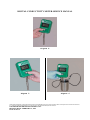
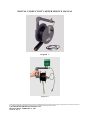
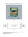
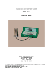
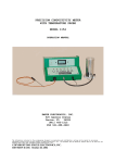
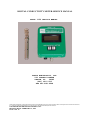
DIGITAL CONDUCTIVITY METER SERVICE MANUAL
MODEL 1152 SERVICE MANUAL
EMCEE ELECTRONICS, INC.
520 CYPRESS AVENUE
VENICE, FL
34285
(941) 485-1515
FAX 941-488-4648
The information contained in the accompanying document is proprietary and confidential, and may not be copied in any manner whatsoever without prior written consent of Emcee Electronics,
Inc. The document and the material therein may not be used for any purpose other than that intended by Emcee Electronics, Inc.
COPYRIGHT 2002 EMCEE ELECTRONICS, INC.
REVISION DATE: FEBRUARY 23, 1996
PAGE 1 OF 14
DIGITAL CONDUCTIVITY METER SERVICE MANUAL
TABLE OF CONTENTS
PAGE
1.0
GENERAL DESCRIPTION . . . . . . . . . . . . . . . . . 3
2.0
TEST EQUIPMENT REQUIREMENTS . . . . . . . . . . . . . 3
3.0
PRELIMINARY CALIBRATION CHECK . . . . . . . . . . . . 3
4.0
BATTERY REPLACEMENT . . . . . . . . . . . . . . . . . 4
5.0
CIRCUIT DESCRIPTION . . . . . . . . . . . . . . . . . 4
6.0
TROUBLE SHOOTING CHART
7.0
CALIBRATION . . . . . . . . . . . . . . . . . . . . . 6
8.0
TEST PROCEDURE
9.0
PARTS LIST
10.0
. . . . . . . . . . . . . . . 6
. . . . . . . . . . . . . . . . . . . 7
. . . . . . . . . . . . . . . . . . . . . 8
ILLUSTRATIONS
FIGURE
FIGURE
FIGURE
FIGURE
FIGURE
FIGURE
FIGURE
FIGURE
FIGURE
FIGURE
FIGURE
FIGURE
1
2
3
4
5
6
7
8
9
10
11
12
METER AND PROBE . . . .
PROBE ATTACHMENT . . . .
PROBE CALIBRATION NO. .
OPERATING POSITION . . .
CALIBRATION MODE . . . .
MEASURE MODE . . . . . .
ACCESSORY CABLE REEL . .
REEL - METER ATTACHMENT
METER INTERNAL VIEW . .
PC BOARD ASSEMBLY . . .
CALIBRATION ACCESSORY .
SCHEMATIC DIAGRAM . . .
.
.
.
.
.
.
.
.
.
.
.
.
.
.
.
.
.
.
.
.
.
.
.
.
.
.
.
.
.
.
.
.
.
.
.
.
.
.
.
.
.
.
.
.
.
.
.
.
.
.
.
.
.
.
.
.
.
.
.
.
.
.
.
.
.
.
.
.
.
.
.
.
.
.
.
.
.
.
.
.
.
.
.
.
.
.
.
.
.
.
.
.
.
.
.
.
. 9
. 9
. 9
.10
.10
.10
.11
.11
.12
.13
.13
.13
SERVICE AND WARRANTY POLICY
See Service & Warranty Manual
The information contained in the accompanying document is proprietary and confidential, and may not be copied in any manner whatsoever without prior written consent of Emcee Electronics,
Inc. The document and the material therein may not be used for any purpose other than that intended by Emcee Electronics, Inc.
COPYRIGHT 2002 EMCEE ELECTRONICS, INC.
REVISION DATE: FEBRUARY 23, 1996
PAGE 2 OF 14
DIGITAL CONDUCTIVITY METER SERVICE MANUAL
1.0
GENERAL DESCRIPTION
1.1 The Emcee Digital Conductivity Meter model 1152 as shown in Figure 1 is
a hand held, battery operated, instrument for determining the conductivity of
fuel samples. Technically, the instrument is a high range ohmmeter capable
of reading between 500 megohms (2000 CU) and infinity (0 CU).
1.2 The controls as shown in Figure 1 consist of a pushbutton switch marked
M (measure) and a pushbutton switch marked C (calibrate).
1.3 Figure 2 shows the instrument with the probe attached and ready for fuel
test.
1.4 Figure 6 shows the instrument in operation with the probe in a fuel
sample.
1.5 The Accessory Cable Kit is shown in Figure 7 and 8. With this reel the
instrument can be used to test fuel in a large storage tank.
1.6 Figure 10 shows the instrument with the back removed, and the plug in
pre-amp and analog to digital PC boards removed.
1.7
2.0
2.1
Figure 11 shows the CU Substitution Box for complete calibration.
TEST EQUIPMENT REQUIREMENTS
CU Substitution Box
2.2
Digital Voltmeter, 10 megohm impedance 0-1 volt +/- .001 0-20 volt
+/- .01.
3.0
3.1
PRELIMINARY CALIBRATION CHECK
Attach probe to bottom connector on the conductivity meter.
3.2 Depress measure switch (marked M). The display should indicate 000 +/001 after 3 seconds. If the display does not indicate 000 +/- 001 remove the
probe and recheck for zero. If the meter will zero without the probe but not
with the probe, the probe should be rinsed with isopropyl alcohol and allowed
to air dry before retesting. If the meter will not zero without probe,
proceed to calibration procedure.
3.3 Depress calibration switch (marked C). The display should
indicate the number on the probe (Figure 3) times 10 +/- 005.
Example:
Probe No. = 42
Display
= 415 – 425
The information contained in the accompanying document is proprietary and confidential, and may not be copied in any manner whatsoever without prior written consent of Emcee Electronics,
Inc. The document and the material therein may not be used for any purpose other than that intended by Emcee Electronics, Inc.
COPYRIGHT 2002 EMCEE ELECTRONICS, INC.
REVISION DATE: FEBRUARY 23, 1996
PAGE 3 OF 14
DIGITAL CONDUCTIVITY METER SERVICE MANUAL
4.0
BATTERY REPLACEMENT
4.1 The model 1152 Conductivity Meter has an internal battery checking
circuit. If batteries are weak the meter will read for a short time and shut
itself off. If batteries are very low the unit will not turn on.
4.2 When battery replacement is indicated remove the 4 screws holding the
back plate exposing the battery housing at the top of the meter.
4.3 Remove the 2 screws on the battery housing and set housing cover to one
side (Figure 10).
4.4 Observe the polarity markings and insert three new batteries as shown in
Figure 10. Battery replacement must be (3) 6 volt Alkaline Nema 1414A Emcee
P/N 152-90-5341. Any other battery replacement will invalidate the CSA and
UL Intrinsically Safe Rating.
4.5
5.0
Replace back panel, check zero and calibration.
CIRCUIT DESCRIPTION
5.1 Power Supply The model 1152 Digital Conductivity Meter uses (3) A-554 6
volt batteries as a single 18 volt power source. Depressing either the
measure or calibrate switches provides power to op amp 1 via D(1) or D(2).
Op amp 1A compares the battery voltage to a positive output at 6 volt zener
reference (ZD-1) and provides a positive output at pin 1 if the battery
voltage is above 13 volts. This insures adequate voltage for good regulation
via VR-1. VR-1 provides a +10 volt (pin 1) and a +5 volt (pin 2) output in
reference to pin 4. The +5 volt (pin 2) output in reference to pin 4. The
+5 volt output is buffered with op amp 1B. The 0 level reference voltage is
developed using the output on op amp 1B pin 7. From this reference point we
now have a +5 volt source and a -5 volt source.
The 0 reference voltage is not attached to the case. Resistors R-15 and R-16
make up a voltage divider to provide a -1 volt source which is tied to the
case. The -1 volt becomes the bias voltage for the fuel probe.
5.2 CALIBRATE REFERENCE - The calibrate voltage is supplied by Q-1 and is
adjustable from 0 to -1 volt. Q-1 is biased on in a saturation mode via R-14
when the calibrate switch is depressed. The collector output is divided by
R-21 and R-20 and the adjustable voltage is passed on to the pre-amp. When
the measure switch is depressed R-13 reverse biases Q-1 and turns Q-1 off.
This action guarantees a 0 volt potential to the pre-amp calibrate input.
The information contained in the accompanying document is proprietary and confidential, and may not be copied in any manner whatsoever without prior written consent of Emcee Electronics,
Inc. The document and the material therein may not be used for any purpose other than that intended by Emcee Electronics, Inc.
COPYRIGHT 2002 EMCEE ELECTRONICS, INC.
REVISION DATE: FEBRUARY 23, 1996
PAGE 4 OF 14
DIGITAL CONDUCTIVITY METER SERVICE MANUAL
5.3 Pre-Amp PC Board - P/N 152-04-0000 The pre-amp board is a separate plugin PC board. Due to the extreme high impedance of the circuit, this board is
very sensitive to humidity. After manufacture, this board is coated with a
conformal coating to reduce outside humidity effects. Since this coating
cannot be removed, the components on this board should not be replaced. Any
failure of the pre-amp board requires a new board assembly. The operation of
this board, however, is to develop a current from the -1 volt bias through
the fuel sample to the op amp pin 2. Pin 2 is maintained at 0 volts via the
positive feedback through R3. With no fuel between the probe electrodes the
pre-amp output should be zero. This is adjusted with zero adjust
potentiometer R-19. During the calibrate period the negative voltage from R20 provides the bias source to the pre-amp and a calibrate reference can be
set.
5.4 A-D Converter PC Board - P/N 152-05-0000 The A-D converter assembly is
a plug-in PC board. The converter is basically a 0 - 1.999 volt., 3 digit
voltmeter. The reference voltage for setting the A-D gain is adjusted by
setting R-18 for approximately 1.0 volts. The final adjustment for this
potentiometer, however, is dependent on R-3 tolerance and variations in the
probe constant. The pre-amp output is fed to the A-D converter which has an
automatic zero adjustment, therefore, any output from the amp can be directly
monitored. The A-D converter directly drives the liquid crystal display
located on the display PC board. The A-D board can be factory repaired.
5.5 Display PC Board P/N 152-03-0000 The display board includes the power
regulator, reference voltage supply, calibration adjustment controls, liquid
crystal display, measure and calibrate switches, and the interconnects for
the A-D and the pre-amp boards. The display board can be factory repaired.
The information contained in the accompanying document is proprietary and confidential, and may not be copied in any manner whatsoever without prior written consent of Emcee Electronics,
Inc. The document and the material therein may not be used for any purpose other than that intended by Emcee Electronics, Inc.
COPYRIGHT 2002 EMCEE ELECTRONICS, INC.
REVISION DATE: FEBRUARY 23, 1996
PAGE 5 OF 14
DIGITAL CONDUCTIVITY METER SERVICE MANUAL
6.0
TROUBLE SHOOTING CHART
MALFUNCTION
Meter does not zero
PROBABLE CAUSE
CORRECTIVE ACTION
Contaminated Probe
Clean thoroughly
with isopropyl
alcohol and air dry
Needs zero adjustment
Adjust zero as per 7.2.
Meter reads above or
below calibration
number during CAL
check
Needs CAL adjustment
Check Pre-amp output
as per 7.0
CU reading erroneous
when CAL check is okay
Contaminated or
damaged probe.
Clean probe with
isopropyl alcohol
and air dry
Inspect probe for
physical damage.
Check electrical
characteristics as
per 7.0
No Display Indication
Lack of supply
voltage
Check connection and/or
replace batteries
MEASURE/CAL switch
defective
Replace Display PC Bd.
P/N 152-03-0000
A-D Converter
defective
Replace A-D PC Bd.
P/N 152-05-0000
+/- 5 Supply In-op
Replace Display PC Bd.
P/N 152-03-0000
7.0 CALIBRATION
7.1 With the back panel removed set R-18 (case hole marked CAL) to
approximately mid scale. The exact setting is not important at this time,
however, the voltage at A-15 should be approximately 1.0 volts above the zero
reference (A-14).
7.2 Remove the probe if attached and depress the measure switch (M).
R-19 (case hole marked ZERO) for a display of 000 +/- 1.
Adjust
The information contained in the accompanying document is proprietary and confidential, and may not be copied in any manner whatsoever without prior written consent of Emcee Electronics,
Inc. The document and the material therein may not be used for any purpose other than that intended by Emcee Electronics, Inc.
COPYRIGHT 2002 EMCEE ELECTRONICS, INC.
REVISION DATE: FEBRUARY 23, 1996
PAGE 6 OF 14
DIGITAL CONDUCTIVITY METER SERVICE MANUAL
7.3 Attach the CU substitution box directly to the conductivity meter using
the 500 CU position.
7.4 Depress the measure switch (M) and adjust R-18 (CAL) for a display
reading of 500 +/- 1.
7.5 Remove the substitution box and repeat the zero adjustment (7.2) if
necessary. If zero adjustment is necessary repeat 7.3 and 7.4 after
readjusting zero.
7.6 Attach the CU substitution box to the conductivity meter using the 100
CU position.
7.7 Depress the measure switch (M) and read the display for linearity.
display should read 100 +/- 1. If the display is outside of tolerance
recheck zero and 500 CU positions.
The
7.8 Remove the plug from the unmarked hole in the case (between the ZERO and
CAL holes) to access R-20 (CAL reference).
7.9 Depress the calibrate switch (C) and adjust R-20 (Cal reference voltage)
for a display or 400 +/- 1.
7.10 Replace the plug removed in step 7.8 (no additional adjustment of R-20
is necessary).
7.11 The instrument is now electrically standardized and should read ZERO =
000 +/- 001, CAL = 400 +/- 001, 500 CU BOX = 500 +/- 001 and 100 CU BOX = 100
+/- 001.
7.12 The meter is then adjusted to the probe for proper fuel measurements.
Identify the probe constant by locating the number stamped on the probe (Fig.
3). Multiply that number by 10 and adjust R-18 (CAL) for that number.
Example:
Probe No. = 42 x 10 = 420
CAL adjust to 420 +/- 001
7.13 The meter is now properly calibrated for fuel measurements.
section 8.0 for operating procedure.
8.0
8.1
Refer to
TEST PROCEDURE
Attach probe to bottom connector on the conductivity meter.
8.2 Depress measure switch (M) with probe OUT of fuel sample. Reading
should be 000 +/- 001 in approximately 3 seconds (Figure 4). If reading is
outside limits remove probe and recheck zero by depressing measure switch.
8.2.2 If zero reading is outside of limits with probe removed, perform
calibration procedure outline in section 7.0.
The information contained in the accompanying document is proprietary and confidential, and may not be copied in any manner whatsoever without prior written consent of Emcee Electronics,
Inc. The document and the material therein may not be used for any purpose other than that intended by Emcee Electronics, Inc.
COPYRIGHT 2002 EMCEE ELECTRONICS, INC.
REVISION DATE: FEBRUARY 23, 1996
PAGE 7 OF 14
DIGITAL CONDUCTIVITY METER SERVICE MANUAL
8.3 Depress Calibrate switch (C) with probe OUT of fuel sample. After 3
seconds reading should be 10 times the probe calibration number +/- 005
(Figure 5).
Example:
Probe No. = 40
Meter Reading = 400 +/- 5 or 395 to 405
8.4 Insert probe in fuel to upper holes and depress measure switch. Report
reading after 3 seconds for stabilization. Due to the polarization of the
fuel sample the apparent reading will continue to change. Only the reading 3
seconds after depressing the measure switch is correct.
9.0
PARTS LIST
Batteries
(3 required)
152-90-5341
Display PC Board
152-03-0000
Pre-Amp PC Board
152-04-0000
A-D Converter PC Board
152-05-0000
Probe
152-09-0000
The information contained in the accompanying document is proprietary and confidential, and may not be copied in any manner whatsoever without prior written consent of Emcee Electronics,
Inc. The document and the material therein may not be used for any purpose other than that intended by Emcee Electronics, Inc.
COPYRIGHT 2002 EMCEE ELECTRONICS, INC.
REVISION DATE: FEBRUARY 23, 1996
PAGE 8 OF 14
DIGITAL CONDUCTIVITY METER SERVICE MANUAL
Figure 1
Figure 2
Figure 3
The information contained in the accompanying document is proprietary and confidential, and may not be copied in any manner whatsoever without prior written consent of Emcee Electronics,
Inc. The document and the material therein may not be used for any purpose other than that intended by Emcee Electronics, Inc.
COPYRIGHT 2002 EMCEE ELECTRONICS, INC.
REVISION DATE: FEBRUARY 23, 1996
PAGE 9 OF 14
DIGITAL CONDUCTIVITY METER SERVICE MANUAL
Figure 4
Figure 5
Figure 6
The information contained in the accompanying document is proprietary and confidential, and may not be copied in any manner whatsoever without prior written consent of Emcee Electronics,
Inc. The document and the material therein may not be used for any purpose other than that intended by Emcee Electronics, Inc.
COPYRIGHT 2002 EMCEE ELECTRONICS, INC.
REVISION DATE: FEBRUARY 23, 1996
PAGE 10 OF 14
DIGITAL CONDUCTIVITY METER SERVICE MANUAL
Figure 7
Figure 8
The information contained in the accompanying document is proprietary and confidential, and may not be copied in any manner whatsoever without prior written consent of Emcee Electronics,
Inc. The document and the material therein may not be used for any purpose other than that intended by Emcee Electronics, Inc.
COPYRIGHT 2002 EMCEE ELECTRONICS, INC.
REVISION DATE: FEBRUARY 23, 1996
PAGE 11 OF 14
DIGITAL CONDUCTIVITY METER SERVICE MANUAL
Figure 9
The information contained in the accompanying document is proprietary and confidential, and may not be copied in any manner whatsoever without prior written consent of Emcee Electronics,
Inc. The document and the material therein may not be used for any purpose other than that intended by Emcee Electronics, Inc.
COPYRIGHT 2002 EMCEE ELECTRONICS, INC.
REVISION DATE: FEBRUARY 23, 1996
PAGE 12 OF 14
DIGITAL CONDUCTIVITY METER SERVICE MANUAL
Figure 10
Figure 11
The information contained in the accompanying document is proprietary and confidential, and may not be copied in any manner whatsoever without prior written consent of Emcee Electronics,
Inc. The document and the material therein may not be used for any purpose other than that intended by Emcee Electronics, Inc.
COPYRIGHT 2002 EMCEE ELECTRONICS, INC.
REVISION DATE: FEBRUARY 23, 1996
PAGE 13 OF 14
DIGITAL CONDUCTIVITY METER SERVICE MANUAL
Figure 12
The information contained in the accompanying document is proprietary and confidential, and may not be copied in any manner whatsoever without prior written consent of Emcee Electronics,
Inc. The document and the material therein may not be used for any purpose other than that intended by Emcee Electronics, Inc.
COPYRIGHT 2002 EMCEE ELECTRONICS, INC.
REVISION DATE: FEBRUARY 23, 1996
PAGE 14 OF 14