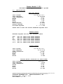
1
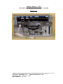
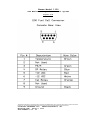
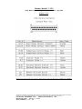
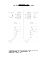
Emcee Model 1150
SDA Monitor & Injection Control System
OPERATION MANUAL
The information contained in the accompanying document is proprietary and confidential, and may not be copied in any manner whatsoever without consent of Emcee
Electronics, Inc. The document and the material therein may not be used for any purpose other that that intended by Emcee Electronics, Inc.
COPYRIGHT SEPTEMBER 2000
EMCEE ELECTRONICS, INC
REVISION DATE
March 4, 2003
PAGE NUMBER 1 of 24
Emcee Model 1150
SDA Monitor & Injection Control System
TABLE OF CONTENTS
1.0
Introduction
2.0
Specifications
3.0
Installation
4.0
Operating Controls
5.0
Operation
6.0
Calibration
7.0
Additive Tank Filling Procedure
8.0
Diagrams
Fig.
Fig.
Fig.
Fig.
Fig.
Fig.
Fig.
Fig.
Fig.
Fig.
Fig.
Fig.
Fig.
Fig.
8.01
8.02
8.03
8.04
8.05
8.06
8.07
8.08
8.09
8.10
8.11
8.12
8.13
8.14
Single Channel Injector
System Overview
Options Package
Console Module Back Panel Connections
Wiring of Fuel Cell Jack
Wiring of Control/Alarm Jack
Wiring of Turbine Jack & Voltage/Current Jumpers
Wiring of 4-20 mA Jack
Console Adjustment Locations
Wiring of Barrier Box
Wiring of Fuel Cell Junction Box (Pre-Amp)
Wiring of Fuel Cell Junction Box (Motor)
Wiring of Injector Control System
Optional Injector Package
Service & Warranty Policy
See Emcee Electronics, Inc Service and Warranty Manual
Additional Data Sheets:
Micropump 200 Installation & Service
Flow Switch, Model V-6
Injector Pump Installation & Service
1150 Software Guide
The information contained in the accompanying document is proprietary and confidential, and may not be copied in any manner whatsoever without consent of Emcee
Electronics, Inc. The document and the material therein may not be used for any purpose other that that intended by Emcee Electronics, Inc.
COPYRIGHT SEPTEMBER 2000
EMCEE ELECTRONICS, INC
REVISION DATE
March 4, 2003
PAGE NUMBER 2 of 24
Emcee Model 1150
SDA Monitor & Injection Control System
1.0
INTRODUCTION
1.1
FUEL CONDUCTIVITY MEASUREMENTS: The ability of a fuel to
dissipate electrical charges generated during pumping and filtering
operations is controlled by it's electrical conductivity. If the
conductivity is sufficiently high, charges dissipate fast enough to
prevent their accumulation and dangerously high voltage potentials
are avoided downstream. Anti-static additives are used to increase
the electrical conductivity of low conductivity products such as
jet and diesel fuels that are loaded at high pumping rates. Since
fuel conductivity depends largely on both the concentration of
anti-static additive and the temperature of the fuel, there is a
need for continuous monitoring of fuel conductivity while it is
being pumped to insure it's within the pre-set limits.
1.2
HOW IT WORKS: A side stream of fuel is taken downstream of
the additive injector and passed through the fuel cell. Two
stainless steel plates located in the fuel stream have a constant
voltage applied. The resulting current is converted by the PreAmplifier into a voltage that is transmitted to the console. The
computer converts the voltage into Picosiemens/meter. The console
is continuously checking for fuel flow and when flow is detected it
starts a proportional injection of the additive mixture. The
proportional ratio is changed by the computer when the requested
conductivity and the actual conductivity are different.
1.3
SAFETY: The 1150 Injection Control System will automatically
adjust the injector frequency to maintain a requested conductivity
level. The instrument can also be used to shut down the system
pumps and /or actuate an alarm if the fuel conductivity goes
outside of preset limits. The fuel cell module is rated by
Underwriters Laboratories (US & Canada) and Kema (Europe) as being
instrinsically safe for use in a hazardous environment. The fuel
cell is also certified by Underwriters Laboratories (UL) for a
working pressure of 150 psig for use with jet fuel, gasoline, and
kerosene. The injector pump and the sidestream pump are UL rated
as explosion proof. These approvals and certifications apply only
when the system is installed as described in this manual with
components purchased from Emcee Electronics, Inc. or their
authorized distributors
1.4
CONTINUOUS IN-LINE MEASUREMENTS: This feature of the 1150
STATICON eliminates the need for hand sampling. Data including
date, time, temperature, and conductivity is automatically saved on
the computer hard drive for each load delivered. A printed report
can be provided for any time period.
1.5
CALIBRATION: The instrument contains an internal electrical
calibration standard. Accurate calibration of the zero and gain
adjustments are conveniently made by screwdriver adjustments at the
control unit. Alarm limits, requested conductivity level and other
parameters are set using both default switches and Keyboard entry.
The information contained in the accompanying document is proprietary and confidential, and may not be copied in any manner whatsoever without consent of Emcee
Electronics, Inc. The document and the material therein may not be used for any purpose other that that intended by Emcee Electronics, Inc.
COPYRIGHT SEPTEMBER 2000
EMCEE ELECTRONICS, INC
REVISION DATE
March 4, 2003
PAGE NUMBER 3 of 24
Emcee Model 1150
SDA Monitor & Injection Control System
2.0
SPECIFICATIONS
FUEL CELL MODULE
INPUT VOLTAGE
INPUT FREQUENCY
POWER CONSUMPTION
HEIGHT
WIDTH
DEPTH
WEIGHT
PROOF PRESSURE
WORKING PRESSURE
FLOW RATE REQUIRED
115 OR 230 V.A.C.
50 OR 60 HZ
225 W.
24 IN.
18 IN.
8 IN.
70 LBS.
750 PSIG
150 PSIG
.3 - 1.0 L MIN
SAMPLE PUMP IN FUEL CELL MODULE GENERATES REQUIRED FLOW
BARRIER MODULE
BARRIERS REQUIRED FOR FUEL CELL INTRINSIC SAFETY
TEMP
OP
CAL
PS/M
-15 V
+15 V
MTL
MTL
MTL
MTL
MTL
MTL
764+
715+
715+
715+
715715+
SHUNT
SHUNT
SHUNT
SHUNT
SHUNT
SHUNT
DIODE
DIODE
DIODE
DIODE
DIODE
DIODE
SAFETY
SAFETY
SAFETY
SAFETY
SAFETY
SAFETY
BARRIER
BARRIER
BARRIER
BARRIER
BARRIER
BARRIER
CONSOLE MODULE
INPUT VOLTAGE
INPUT FREQUENCY
POWER CONSUMPTION
HEIGHT
WIDTH
DEPTH
WEIGHT
115 OR 230 V.A.C.
50 OR 60 HZ
150 W.
10.5 IN.
17 IN.
13 IN.
50 LBS.
INJECTOR MODULE (INCLUDING 165 GALLON TANK)
INPUT VOLTAGE
INPUT FREQUENCY
POWER CONSUMPTION
HEIGHT
WIDTH
DEPTH
WEIGHT
115 V.A.C.
60 HZ
150 W.
36 IN.
60 IN.
60 IN.
350 LBS.
The information contained in the accompanying document is proprietary and confidential, and may not be copied in any manner whatsoever without consent of Emcee
Electronics, Inc. The document and the material therein may not be used for any purpose other that that intended by Emcee Electronics, Inc.
COPYRIGHT SEPTEMBER 2000
EMCEE ELECTRONICS, INC
REVISION DATE
March 4, 2003
PAGE NUMBER 4 of 24
Emcee Model 1150
SDA Monitor & Injection Control System
3.0
INSTALLATION
3.1
CONSOLE AND BARRIER INSTALLATION:
3.1.1
The 1150 console should be located in the office or control
building used for monitoring output data and local alarms. The
console is a standard equipment rack and can be located on a bench
or other support. The console includes a computer monitor that
will display the requested and actual conductivities, temperature,
gallons dispensed, injection quantity as well as the adjustments
for calibration and limit settings.
3.1.2
The console can be powered by either a 115 or 230 volt AC
supply. A selector switch is located on the rear of each supply to
select the voltage option.
3.1.3
The barrier box should also be installed near the console.
A 6 ft. cable is provided to connect the console and the barrier
box. The barrier box should be wall mounted where the input cable
can reach the console and the output can be connected to the fuel
cell area. The installation requires a dedicated conduit from the
barrier box to the upper junction box on the fuel cell module.
3.1.4
The Electrical Interface connection locations made to the
rear of the console system are shown in Figure 8.04.
3.1.5
The Turbine or Pipeline Flow-meter connection is shown in
Figures 8.02 & 8.07. This will typically be available from the
product delivery system and must be a pulse train with increments
of 1.0 gallons. The jumpers shown allow for either a voltage or
current signal interface.
3.1.6
When No Turbine pulse train providing flow data is
available an external contact closure must be provided to activate
the monitor function. Closing of this contact shown in Fig. 8.06
will start the internal data recorder and turn on the conductivity
display. Actual injection control will need turbine input data for
proper operation.
3.2
INJECTOR SYSTEM & FUEL CELL MODULE INSTALLATION:
3.2.1
The injector system includes the additive tank, injector
pump, fuel cell module , base support system, electrical
connections, and plumbing connections. The fuel cell module
includes the side-stream pump, sample relaxation chamber, a sidestream flow switch, the fuel cell and electrical junction boxes.
3.2.2
Locate the injector system near the pipeline or tank to be
monitored and controlled. The distance between the fuel cell
module and the item being monitored is not critical; however, the
volume of the sampling piping will delay the reading due to the
sample flow rate limitation. The injection line should be routed
up-stream to allow proper mixing of the additive with the product
The information contained in the accompanying document is proprietary and confidential, and may not be copied in any manner whatsoever without consent of Emcee
Electronics, Inc. The document and the material therein may not be used for any purpose other that that intended by Emcee Electronics, Inc.
COPYRIGHT SEPTEMBER 2000
EMCEE ELECTRONICS, INC
REVISION DATE
March 4, 2003
PAGE NUMBER 5 of 24
Emcee Model 1150
SDA Monitor & Injection Control System
before reaching the monitor sample point.
injection line is not critical.
The length of the
3.2.3
The monitor sample line (input & output) should be a 1/4 to
3/8 stainless steel tubing. The taps for these lines should draw a
sample that represents the fuel being delivered.
3.2.4
The sample pump and the injection pump are powered by a
115V 60 Hz. AC source. Figures 8.12 & 8.13 detail the explosion
proof wiring connections.
3.2.5
An earth grounding connection should be made to the fuel
cell module. This earth connection may be made via the supporting
frame or a separate wire attached to the fuel cell module rear
panel from a ground rod.
3.2.6
The fuel cell intrinsically safe wiring is made with a
seven conductor cable. The routing for this cable should be a
separate dedicated conduit. Cable lengths not exceeding 1000 ft.
should be run with #22 gauge Alpha 1177 cable. Length requirements
of 1000 - 2000 ft. require 18 gauge Alpha 1898/7 cable. The cable
is pulled through the conduit installed between the barrier box and
the junction box located on the upper left side of the fuel cell
module. The color coding for the terminal connections is shown in
Figures 8.10 & 8.11.
3.3
REMOTE ALARM AND CONTROL CONNECTIONS: The Staticon is
completely operational as a monitor system without additional
connections being made, however the use of remote signal and
control can prevent dispensing product which is out of the pre-set
conductivity limits.
3.4
REMOTE DATA: Two 4 – 20 mA outputs are provided on the rear
of the injector control board for sending temperature and
conductivity data to a remote meter, recorder, or computer system.
4.0
OPERATING CONTROLS
4.1
System Power Switch:
The System Power switch controls the
power to all components of the console system.
4.2
Auto/Manual Switch:
The additive concentration is
controlled with a proportional injection technique. In order to
accomplish this task flow data is fed to the injection controller
board and the injector pump is pulsed each time a specific quantity
of fuel is delivered. The Auto/Manual switch located on the
injection controller front panel is used to select a pre-set
gallons per injection in the Manual mode or a computer controlled
gallons per injection in the Auto mode. The normal position for
this switch is Auto.
4.3
Zero Switch:
The Zero switch is part of the calibration
procedure and when depressed will allow you to check the fuel cell
pre-amp output for zero reference.
The information contained in the accompanying document is proprietary and confidential, and may not be copied in any manner whatsoever without consent of Emcee
Electronics, Inc. The document and the material therein may not be used for any purpose other that that intended by Emcee Electronics, Inc.
COPYRIGHT SEPTEMBER 2000
EMCEE ELECTRONICS, INC
REVISION DATE
March 4, 2003
PAGE NUMBER 6 of 24
Emcee Model 1150
SDA Monitor & Injection Control System
4.4
Calibrate Switch:
The Calibrate switch is part of the
calibration procedure and when depressed will simulate a specific
conductivity value to verify the system gain adjustment.
4.5
PUMP Switch:
The Pump switch can be used to check the
conductivity of the fuel in the fuel cell loop. Pressing the
switch will turn on the side stream pump and activate the LCD
Display of the fuel conductivity. The display reads the current
conductivity in PS/M.
4.6
Monitor, Keyboard and Trackball:
The optional monitor,
keyboard and trackball can be used to check files, change
configuration, and generally operate the onboard computer. If
these options are not used the same functions can be completed via
an external computer using either a serial cable or modem
connection.
4.7
Default Value Switches:
Default values include the manual
mode gallons per injection rate and the requested conductivity
value. These switches are located on the rear of the Injector
control board and are identified in Figure 8.04.
5.0
OPERATION
5.1
When all of the cables are connected to the proper terminals
the following selections should be made.
5.1.1
Turn the System Power Switch to ON.
5.1.2
Set the Auto/Manual Switch to the Auto position.
5.2
After the Computer completes the normal boot process it will
automatically load and run the additive injection program. All
injection control and record maintenance is automatically initiated
when flow is detected in the pipeline.
5.3
The program is continuously scanning the injector control
module to detect any pipeline fuel flow. The fuel flow is measured
by the turbines in the distribution system and any turbine pulsetrain will start the injection system. When using the turbine
emulator described in 3.1.6 the gpm is a preset number not relative
to actual flow. This prevents true injection per unit measure
control but can be used with a simple flow switch to activate the
console CPU. Attachment of the turbine emulator is shown in Fig.
8.15.
5.4
When flow is detected the monitor screen will start reporting
the current fuel conditions. The screen will indicate the
requested conductivity, the actual conductivity, the fuel
temperature, the gallons per minute flow rate, the total gallons
loaded for the current load, and the number of injections used for
this load.
5.5
The injection ratio is initially started at the same ratio
the previous load required. As the new fuel load progresses the
The information contained in the accompanying document is proprietary and confidential, and may not be copied in any manner whatsoever without consent of Emcee
Electronics, Inc. The document and the material therein may not be used for any purpose other that that intended by Emcee Electronics, Inc.
COPYRIGHT SEPTEMBER 2000
EMCEE ELECTRONICS, INC
REVISION DATE
March 4, 2003
PAGE NUMBER 7 of 24
Emcee Model 1150
SDA Monitor & Injection Control System
computer will modify the injection ratio (Gallons of fuel per
injection pulse) as necessary to bring the actual conductivity to
match the requested conductivity.
5.6
The screen report will continue until the fuel flow returns
to zero. At that time a file will be written to the hard disk with
a detailed report of the measured parameters taken at approximately
one minute intervals. A summary report is also generated that
provides an average of the load conductivity and temperature. The
summary also indicates the date, time, fuel quantity, number of
injections and injection ratio.
5.7
Alarm contacts can be used to shut down the pipe-line flow
when the fuel conductivity does not meet pre-set low and high
limits. The configuration file can be edited to adjust the
conductivity limits and time limits to prevent false alarms. The
software configuration will be covered in the calibration and
adjustment section of this manual.
5.8
5.8.1
Operator Control Functions
Staticon File Monitoring
5.8.1.1
The injector control module will continue to operate as
normal if you minimize the program while you check file or change
configuration settings. It is still recommended however that
changes to the configuration file be made when no fuel is being
loaded. Any changes will not be completed until the program is
restarted.
5.8.1.2
After minimizing the Staticon Injector program select the
Staticon Files program. This program allows you to review all
previous fuel loading in either summary (load average and totals)or
detail (records taken at intervals during loading) format.
5.8.1.3
Selection of item 1. displays the most recent fuel load
in summary format and list the number of loads completed during
this calendar month. Pressing <Enter> will display the previous
load in summary format. To return to the main menu enter an S for
stop. To see more detail for the load enter a D for detail.
5.8.1.4
When the summary format is selected the screen displays
the date and time of loading, total gallons, total additive
injections, average conductivity, and average temperature.
5.8.1.5
When the detail format is selected the screen will
display the date and time the record was saved. The record
includes the gallons loaded, conductivity, temperature, injections,
and mode selections at that time. Pressing the enter progresses
through each record available for that load. To return to the
summary format, enter a S for stop.
The information contained in the accompanying document is proprietary and confidential, and may not be copied in any manner whatsoever without consent of Emcee
Electronics, Inc. The document and the material therein may not be used for any purpose other that that intended by Emcee Electronics, Inc.
COPYRIGHT SEPTEMBER 2000
EMCEE ELECTRONICS, INC
REVISION DATE
March 4, 2003
PAGE NUMBER 8 of 24
Emcee Model 1150
SDA Monitor & Injection Control System
5.8.1.6
Selection of item 2 from the main menu will allow you to
look at data from previous months. After entering the year and
selecting the month the load files will be presented in summary and
detail mode as described in previous section. Detail files are
automatically erased after 1 year and summary files after 2 years.
5.8.2
Staticon Configuration Editor
5.8.2.1
After minimizing the Staticon Injector program select the
Staticon Configuration program. This program allows you to enter
the company name, the product type, upper and lower shutdown
limits, and use of a printer for hard copy summary records.
5.8.2.2
(Company Name)
Selecting this option allows you to
change the name on the screen display and the internal report.
5.8.2.3
(Product Description)
Selecting this option allows
you to change the name such as Jet-A or Diesel on the screen
display and the internal report.
5.8.2.4
(High Conductivity Limit)
Selecting this option
allows you to set an upper conductivity limit for the fuel being
delivered. If the actual conductivity exceeds the high limit the
alarm relay will activate. This relay has two sets of contacts and
can be used to operate an alarm or shut down the fuel delivery
system. High conductivity problems are very rare and would
indicate a problem with the injection system or a very strong
additive blend.
5.8.2.5
(Low Conductivity Limit)
Selecting this option allows
you to set a low conductivity limit for the fuel being delivered.
If the actual conductivity is below the low limit the alarm relay
will activate. Low conductivity problems indicate a problem with
the injection system (typically an empty additive tank) or a very
weak additive blend.
5.8.2.6
(Printer Option)
When the printer option is “yes” the
parallel port will send out a summary report at the end of each
load.
The information contained in the accompanying document is proprietary and confidential, and may not be copied in any manner whatsoever without consent of Emcee
Electronics, Inc. The document and the material therein may not be used for any purpose other that that intended by Emcee Electronics, Inc.
COPYRIGHT SEPTEMBER 2000
EMCEE ELECTRONICS, INC
REVISION DATE
March 4, 2003
PAGE NUMBER 9 of 24
Emcee Model 1150
SDA Monitor & Injection Control System
6.0
CALIBRATION
6.1
The electrical and fuel conductivity calibration has been
pre-set at the factory and adjustment should not be necessary
unless a major component is replaced.
6.2
The routine calibration check recommended is simply comparing
the 1150 readings with a recently calibrated portable instrument
such as the Model 1152. This is done by drawing a fuel sample from
the same source as the fuel cell module. Check the conductivity of
the sample using the portable instrument before the temperature is
allowed to change. The comparison results should meet the ASTM D2624 precision.
6.3
Electrical Zero and Gain adjustments can be evaluated at any
time by pressing the Zero and Calibrate switches located on the
console front panel.
6.3.1
Depress the Zero switch and hold it for 30 seconds to
verify the pre-amp zero calibration. Acceptable readings are +/30 due to charges on the fuel surface. A more exact zero
adjustment requires removal of the pre-amp board and is not
normally required.
6.3.2
Depress the Calibrate switch and hold it for 30 seconds to
verify the Gain adjustment. A calibration number is stamped on the
fuel cell when factory fuel tests are made.
If the amplifier gain
is correct that number will appear on the monitor +/-10%.
6.4
Variations of the additive mix concentration and temperature
extremes may require a change in the injector pump calibration.
There are two knobs on the injector, the top being a manual pulse
selector. The selection of this knob should always be fully
counter clockwise; this position allows the controller board to
control the pump operation. The bottom knob sets the stroke length
for each pump injection cycle. This knob should only be turned
while the pump is running and only when it is determined that the
gallons per injection is not correct. Typically a gallons per
injection between 5 and 25 provide good blending and the stroke
length of 50 to 70% should be used if possible.
6.5
The Controller Board adjustments are shown in Fig. 8.09. The
adjustments are located behind the removable panel on the front of
the Injector Control Assembly. Adjustment of these controls
requires several pieces of test equipment and the procedure is
described in our 1150 Calibration Manual.
The information contained in the accompanying document is proprietary and confidential, and may not be copied in any manner whatsoever without consent of Emcee
Electronics, Inc. The document and the material therein may not be used for any purpose other that that intended by Emcee Electronics, Inc.
COPYRIGHT SEPTEMBER 2000
EMCEE ELECTRONICS, INC
REVISION DATE
March 4, 2003
PAGE NUMBER 10 of 24
Emcee Model 1150
SDA Monitor & Injection Control System
7.0
Additive Tank Filling Procedure
7.1
A 5% blend of Stadis 450 in Jet-A is a typical cocktail
mixture for this additive. In order to get the best mixing we
recommend the Stadis 450 be poured into a Layer of Jet-A followed
by additional Jet-A to mix the components.
7.2
With an empty tank open the tank fill valve to allow Jet-A to
enter the tank. Measure the level with a yardstick and fill to
approximately 10 inches. (21 inches will be approximately 100
Gallons)
7.3
Shut off the Jet-A valve and pour 5 Gallons of Stadis 450
into the additive port.
7.4
Open the Jet-A Valve and allow the tank to fill to the 21
inch level. Shut off the tank fill valve and open the valve to the
Fuel Cell Module for conductivity monitoring.
The information contained in the accompanying document is proprietary and confidential, and may not be copied in any manner whatsoever without consent of Emcee
Electronics, Inc. The document and the material therein may not be used for any purpose other that that intended by Emcee Electronics, Inc.
COPYRIGHT SEPTEMBER 2000
EMCEE ELECTRONICS, INC
REVISION DATE
March 4, 2003
PAGE NUMBER 11 of 24
Emcee Model 1150
SDA Monitor & Injection Control System
8.0
Diagrams
Figure 8.01
The information contained in the accompanying document is proprietary and confidential, and may not be copied in any manner whatsoever without consent of Emcee
Electronics, Inc. The document and the material therein may not be used for any purpose other that that intended by Emcee Electronics, Inc.
COPYRIGHT SEPTEMBER 2000
EMCEE ELECTRONICS, INC
REVISION DATE
March 4, 2003
PAGE NUMBER 12 of 24
Emcee Model 1150
SDA Monitor & Injection Control System
Figure 8.02
The information contained in the accompanying document is proprietary and confidential, and may not be copied in any manner whatsoever without consent of Emcee
Electronics, Inc. The document and the material therein may not be used for any purpose other that that intended by Emcee Electronics, Inc.
COPYRIGHT SEPTEMBER 2000
EMCEE ELECTRONICS, INC
REVISION DATE
March 4, 2003
PAGE NUMBER 13 of 24
Emcee Model 1150
SDA Monitor & Injection Control System
Figure 8.03
The information contained in the accompanying document is proprietary and confidential, and may not be copied in any manner whatsoever without consent of Emcee
Electronics, Inc. The document and the material therein may not be used for any purpose other that that intended by Emcee Electronics, Inc.
COPYRIGHT SEPTEMBER 2000
EMCEE ELECTRONICS, INC
REVISION DATE
March 4, 2003
PAGE NUMBER 14 of 24
Emcee Model 1150
SDA Monitor & Injection Control System
Figure 8.04
The information contained in the accompanying document is proprietary and confidential, and may not be copied in any manner whatsoever without consent of Emcee
Electronics, Inc. The document and the material therein may not be used for any purpose other that that intended by Emcee Electronics, Inc.
COPYRIGHT SEPTEMBER 2000
EMCEE ELECTRONICS, INC
REVISION DATE
March 4, 2003
PAGE NUMBER 15 of 24
Emcee Model 1150
SDA Monitor & Injection Control System
Figure 8.05
The information contained in the accompanying document is proprietary and confidential, and may not be copied in any manner whatsoever without consent of Emcee
Electronics, Inc. The document and the material therein may not be used for any purpose other that that intended by Emcee Electronics, Inc.
COPYRIGHT SEPTEMBER 2000
EMCEE ELECTRONICS, INC
REVISION DATE
March 4, 2003
PAGE NUMBER 16 of 24
Emcee Model 1150
SDA Monitor & Injection Control System
Figure 8.06
The information contained in the accompanying document is proprietary and confidential, and may not be copied in any manner whatsoever without consent of Emcee
Electronics, Inc. The document and the material therein may not be used for any purpose other that that intended by Emcee Electronics, Inc.
COPYRIGHT SEPTEMBER 2000
EMCEE ELECTRONICS, INC
REVISION DATE
March 4, 2003
PAGE NUMBER 17 of 24
Emcee Model 1150
SDA Monitor & Injection Control System
Figure 8.07
The information contained in the accompanying document is proprietary and confidential, and may not be copied in any manner whatsoever without consent of Emcee
Electronics, Inc. The document and the material therein may not be used for any purpose other that that intended by Emcee Electronics, Inc.
COPYRIGHT SEPTEMBER 2000
EMCEE ELECTRONICS, INC
REVISION DATE
March 4, 2003
PAGE NUMBER 18 of 24
Emcee Model 1150
SDA Monitor & Injection Control System
Figure 8.08
The information contained in the accompanying document is proprietary and confidential, and may not be copied in any manner whatsoever without consent of Emcee
Electronics, Inc. The document and the material therein may not be used for any purpose other that that intended by Emcee Electronics, Inc.
COPYRIGHT SEPTEMBER 2000
EMCEE ELECTRONICS, INC
REVISION DATE
March 4, 2003
PAGE NUMBER 19 of 24
Emcee Model 1150
SDA Monitor & Injection Control System
Figure 8.09
Figure 8.10
The information contained in the accompanying document is proprietary and confidential, and may not be copied in any manner whatsoever without consent of Emcee
Electronics, Inc. The document and the material therein may not be used for any purpose other that that intended by Emcee Electronics, Inc.
COPYRIGHT SEPTEMBER 2000
EMCEE ELECTRONICS, INC
REVISION DATE
March 4, 2003
PAGE NUMBER 20 of 24
Emcee Model 1150
SDA Monitor & Injection Control System
Figure 8.11
The information contained in the accompanying document is proprietary and confidential, and may not be copied in any manner whatsoever without consent of Emcee
Electronics, Inc. The document and the material therein may not be used for any purpose other that that intended by Emcee Electronics, Inc.
COPYRIGHT SEPTEMBER 2000
EMCEE ELECTRONICS, INC
REVISION DATE
March 4, 2003
PAGE NUMBER 21 of 24
Emcee Model 1150
SDA Monitor & Injection Control System
Figure 8.12
The information contained in the accompanying document is proprietary and confidential, and may not be copied in any manner whatsoever without consent of Emcee
Electronics, Inc. The document and the material therein may not be used for any purpose other that that intended by Emcee Electronics, Inc.
COPYRIGHT SEPTEMBER 2000
EMCEE ELECTRONICS, INC
REVISION DATE
March 4, 2003
PAGE NUMBER 22 of 24
Emcee Model 1150
SDA Monitor & Injection Control System
Figure 8.13
The information contained in the accompanying document is proprietary and confidential, and may not be copied in any manner whatsoever without consent of Emcee
Electronics, Inc. The document and the material therein may not be used for any purpose other that that intended by Emcee Electronics, Inc.
COPYRIGHT SEPTEMBER 2000
EMCEE ELECTRONICS, INC
REVISION DATE
March 4, 2003
PAGE NUMBER 23 of 24
Emcee Model 1150
SDA Monitor & Injection Control System
Figure 8.14
The information contained in the accompanying document is proprietary and confidential, and may not be copied in any manner whatsoever without consent of Emcee
Electronics, Inc. The document and the material therein may not be used for any purpose other that that intended by Emcee Electronics, Inc.
COPYRIGHT SEPTEMBER 2000
EMCEE ELECTRONICS, INC
REVISION DATE
March 4, 2003
PAGE NUMBER 24 of 24