1
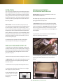
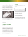
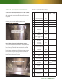
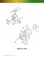
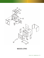
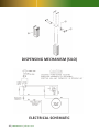
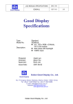
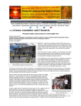
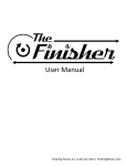
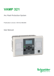
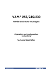
Plate Heater
Service Manual
Models CPH2 & CPH3
888-892-2213 | alluserv.com
Plate Heater
Service Manual
Models CPH2 & CPH3
Table of Contents
Introduction . . . . . . . . . . . . . . . . . . . . . . . . . . . . . . . . . . . . . . . . . . . . . . . . . . .2
Freight Claims . . . . . . . . . . . . . . . . . . . . . . . . . . . . . . . . . . . . . . . . . . . . . . . . . .3
Electrical Information . . . . . . . . . . . . . . . . . . . . . . . . . . . . . . . . . . . . . . . . . . .3
Operation . . . . . . . . . . . . . . . . . . . . . . . . . . . . . . . . . . . . . . . . . . . . . . . . . . . . .4
Installation & Start-up . . . . . . . . . . . . . . . . . . . . . . . . . . . . . . . . . . . . . . . . . . .4
Spring Adjustment . . . . . . . . . . . . . . . . . . . . . . . . . . . . . . . . . . . . . . . . . . . . . .5
Cleaning . . . . . . . . . . . . . . . . . . . . . . . . . . . . . . . . . . . . . . . . . . . . . . . . . . . . . .5
Troubleshooting . . . . . . . . . . . . . . . . . . . . . . . . . . . . . . . . . . . . . . . . . . . . . . . .6
Service Access Information . . . . . . . . . . . . . . . . . . . . . . . . . . . . . . . . . . . . . .7
Replacement Parts List . . . . . . . . . . . . . . . . . . . . . . . . . . . . . . . . . . . . . . . . . .7
Replacement Parts Diagram CPH2 . . . . . . . . . . . . . . . . . . . . . . . . . . . . . . . .8
Replacement Parts Diagram CPH3 . . . . . . . . . . . . . . . . . . . . . . . . . . . . . . . .9
Replacement Parts Diagram Dispensing Mechanism . . . . . . . . . . . . . . .10
Electrical Schematic . . . . . . . . . . . . . . . . . . . . . . . . . . . . . . . . . . . . . . . . . . .10
Warranty . . . . . . . . . . . . . . . . . . . . . . . . . . . . . . . . . . . . . . . . . . . . . . . . . . . . .11
2 | 888-892-2213 | alluserv.com
IntroductIon
This manual contains installation instructions, operational instructions, replacement parts lists, wiring schematics and
troubleshooting information. It should
be retained for future reference. Should
you have any questions concerning this
equipment call 888-892-2213.
Important: FOR yOuR SAFETy, READ AnD
FOLLOW ALL InSTRuCTIOnS, WARnIngS,
CAuTIOnS AnD OPERATIOnAL InSTRuCTIOnS.
FreIght damage claIms
Alluserv cannot assume responsibility for loss or damage
suffered in transit. The carrier assumes full responsibility
of delivery in good order when shipment is accepted and
signed for by you the customer.
This equipment was carefully inspected and packed prior
to leaving the factory. Alluserv cannot assume responsibility for damage or loss incurred in transit. At the time of
delivery, visible damage or loss must be noted on the
freight bill or express receipt and signed by the carrier’s
agent. Failure to adequately describe such external evidence of loss or damage may result in the carrier refusing
to honor a damage claim. The form required to file such a
claim will be supplied by the carrier. It is your responsibility, the customer, to file the claim.
Concealed loss or damage means loss or damage that
does not become apparent until the merchandise has
been unpacked. The contents may be damaged in transit
due to rough handling even though the carton may not
show external damage. When the damage is discovered
during the unpacking of the product, make a written request for inspection by the carrier within fifteen (15) days
of the delivery date. The carrier will provide you with the
proper form. It is very important to keep all cartons, packing materials and skids for the agent’s inspection. DO
nOT RETuRn DAMAgED MERCHAnDISE TO
ALLuSERV. FILE yOuR CLAIM WITH THE CARRIER.
WarnIngs:
1. Installation of this equipment should be performed only by persons qualified or licensed to install electrical equipment.
2. Adjustments and service work should be performed only by a qualified service technician. Service is available thru Alluserv Authorized Parts &
Service network.
3. This equipment is intended for commercial use
only. not for household use.
4. use of other than genuine Alluserv replacement
parts during the warranty period will invalidate the
equipment warranty. To maintain the equipment
warranty, all service work must be performed by an
Alluserv authorized service agent.
5. never use corrosive cleaners. use only cleaners
approved for stainless steel.
6. To prevent an electrical shock hazard, prior to
performing service and internal cleaning of the unit,
the main power switch(s) must be turned to the
“Off” position and the unit unplugged from the
electrical source.
7. This unit must not be allowed to run continuously. This will cause the hi-limit thermostat to
cycle and shut down electrical power to the heating
element. The unit MuST be turned off at night.
electrIcal InFormatIon
For all models
Voltage: . . . . . .208/240 Volts Single Phase 60 cycle
total amperage: . . . . . . . . . . . . . . . . . . . . . . .16.3
nema plug conFIguratIon: . . . . . . . . . . .6-20P
total heater Wattage: . . . . . . . . . . . . . . . . .3200
WarnIng: THE unIT IS EquIPPED WITH
A gROunDED POWER CORD AnD PLug MuST
bE COnnECTED TO A PROPERLy gROunDED
RECEPTACLE AnD A DEDICATED CIRCuIT
bREAkER RATED 20 AMPS.
alluserv.com | 888-892-2213 |
3
operatIon
The unit comes equipped with an adjustable thermostat
that is adjustable from 175 to 215˚ F. Once the temperature inside the cabinet is reached the preset thermostat
setting, the thermostat will cycle on and off to maintain
the preset temperature. The motor and fan will operate
continuously as long as the lighted “On-Off” switch is in
the “On” position.
Important: The internal cabinet temperature will
vary. Once the internal temperature has stabilized, the internal temperature will be at the preset setting (175 to
215˚ F.) at the thermostat sensing disc. However, internal
temperatures will vary within the heated compartment.
From a cold start, two (2) hours is recommended to heat
the plates to the proper temperature. If warm plates are
inserted for heating, allow one and one half (1 ½) hours
for the subsequent cycles.
sprIng adjustment
dIspensIng mechanIsm
Important: SPRIng ADjuSTMEnT IS nOT COVERED unDER WARRAnTy!
The dispensing springs are preset for Alluserv bases. If
spring adjustments are required:
1. cautIon: Turn the unit off, open the lids and allow
for the internal temperature of the cabinet to cool down
to room temperature. cautIon: The bases will remain
hot for a long period of time. To remove them use heat
resistant gloves or a suction lifter. use insulated gloves to
remove plates.
2. Open the lids, remove the lift out divider located between the dispensing mechanisms.
To maintain proper operation, the lids must be kept
closed except when inserting or removing plates.
InstallatIon and start-up
1. Carefully remove all external packaging material and
carefully roll the unit off of the wooden skid. If damage is
discovered, retain all packing materials and immediately
file a concealed shipping damage claim with the transportation company.
2. Remove all tape and protective coatings from the unit.
3. Important: Lift out the self leveling dispenser mechanisms and remove the corrugated packing materials
from the cabinet.
3. Lift the dispensing mechanism out of the dispenser by
grasping the handles located on each side of the dispenser.
4. Connect the unit to a proper electrical power source.
5. Load the unit with plates. Since plates vary in height
and weight, the quantity will vary.
6. Close the lids and turn the
“On-Off” switch “On”. When
the switch is on, the switch
will light up.
4 | 888-892-2213 | alluserv.com
4. Place the dispensing mechanism upright on the floor
5. Place ten (10) each bases into the silo. Adjust spring by
reconnecting or disconnecting springs. Important, to
maintain even dispensing of the bases, there must be an
even amount of springs connected on each side of the
dispensing mechanism. If bases or plates come up too
high, remove an even amount of springs on each side of
the dispenser mechanism. If more tension is required,
connect springs or add new springs as needed.
cleanIng
cautIon: Prior to cleaning, turn the “On-Off” switch to
the “Off” position and unplug the unit from the electrical
power source.
danger: nEVER SPRAy WASH OR uSE ExCESSIVE
WATER DuRIng CLEAnIng. THIS COuLD SHORT
OuT ELECTRICAL COMPOnEnTS, CAuSE An ELECTRICAL SHOCk HAzARD AnD DAMAgE THE unIT.
exterIor cleanIng:
Clean using a mild, non-chlorinated cleaner approved for
stainless steel. Wipe dry with a soft cloth.
Periodically check the casters for proper operation and remove mop strings and other obstructions.
6. To confirm the adjustment, insert a full complement of
bases and adjust accordingly. Important: The bases
will come up to within 2 to 3 inches of the top of the silo.
InterIor cleanIng:
Open lids and remove the dispensing mechanism. Clean
the dispensing mechanism and interior of the unit using a
mild, non-chlorinated cleaner. Wipe dry with a soft cloth.
7. Once springs have been adjusted, remove all of the
bases from the dispensing mechanism and place it back
into the dispenser.
thermostat adjustment
Important: Thermostat adjustment is not covered
under warranty.
cautIon: Prior to making any adjustments, turn both
“On-Off” switches to the “Off” position and unplug unit
from electrical power source. units have an adjustable
thermostat with a range of 175 to 215˚ F. To adjust the
thermostat, once switches have been turned off and the
unit has been unplugged, remove the back panel by removing two (2) screws at the top (See “Service Access”
section of this manual). Locate the “Plate” side adjustable
thermostat and turn the pointer to a higher or lower temperature. Install back panel, plug unit into electrical
power source and continue with the operation.
alluserv.com | 888-892-2213 |
5
troubleshootIng
cautIon: Prior to performing any service repair, turn the “On-Off” switch to the “Off” position and unplug the unit from
the electrical power source!
complaInt
problem
solutIon
A
unit does not heat but the fan operates
1. Open Hi-Limit thermostat.
2. Loose wiring.
3. Defective heating element.
1. Reset Hi-Limit or replace if faulty
2. Repair loose wiring
3. Replace defective heating element
b
unit heats but fan does not blow
1. Defective motor.
2. jammed or loose fan blade.
3. Loose wiring
1. Replace motor.
2. Replace or tighten fan blade.
3. Repair loose wiring
C
unit does not operate and light does not
come on
1. no electrical power to unit
2. Faulty power switch.
3. Loose wiring
1. Make sure that unit is plugged in.
Check power at receptacle.
2. Replace “On-Off” switch.
3. Repair loose wiring
D
base temperature too low
1. Lids left open.
2. Cycle time too short.
3. Loose fan blade.
1. Close lids
2. Allow proper cycle time
3. Tighten or replace fan blade.
E
base temperature too high
Faulty operating thermostat
Replace operating thermostat
F
Cabinet not easy to roll/move
1. Debris on wheel of axel
2. no lubrication
1. Remove debris
2. Lubricate/grease casters
g
bases do not dispense properly
1. Faulty springs
2. not enough springs
3. Faulty bushings
4. Debris on guide rods
1. Replace springs
2. Add springs as needed
3. Replace bushings
4. Clean out debris
6 | 888-892-2213 | alluserv.com
serVIce access InFormatIon
access to the motor, thermostats and “on-off” switch:
cautIon: Prior to performing any service, turn the “OnOff” switch “Off” and unplug the unit from the electrical
receptacle.
To access these components, remove the back panel by
removing two (2) screws at the top of the panel.
motor, blower wheel and heating element access:
To access the blower wheel and motor, remove the back
panel by removing two (2) screws at the top of the panel
(see above). Open the lids and remove the lift out filler
panel located between the dispensing mechanisms. Lift
the dispensing mechanisms out of the unit. next remove
the internal access panel that guards the fan blade and
heating element. This will provide access to the motor,
blower wheel and heating element.
replacement parts
No
Description
Part
Number
CBH2
Qty.
CBH3
Qty.
1
Lid Assembly (End)
5036
2
2
2
Lid Assembly (Center)
5037
__
1
3
Hinge
5055
4
6
4
Switch Guard
5056
1
1
5
Lid Handle
5049
2
3
6
Push/Pull Handle
5038
1
1
7
Cord-10 Ft.
_______
1
1
8
Plug 20 Amp (NEMA 620P)
5042
1
1
9
On/Off Switch
5043
1
1
10
Motor 208/240 V 3200
RPM
5033
1
1
11
Thermostat Adjustable
175 to 215 F
5048
1
1
12
Thermostat
Hi-Limit (350 F)
5045
1
1
13
Heating Element
208/240 V.3200 Watt
5039
1
1
14
Blower Wheel
5034
1
1
15
Caster-Swivel
No Brake
5031
2
2
16
Caster-Swivel With
Brake
5032
2
2
17a
Spring - Standard
5051
20
30
17b
Spring Heavy Duty
5052
As
Needed
As Needed
18
Bushing Dispenser
5050
8
12
19
Dispensing Mechanism
Complete
5057
2
3
20
Corner Bumpers
5053
4
4
alluserv.com | 888-892-2213 |
7
MoDel CPH2
8 | 888-892-2213 | alluserv.com
MoDel CPH3
alluserv.com | 888-892-2213 |
9
DisPeNsiNg MeCHaNisM (silo)
eleCtriCal sCHeMatiC
10 | 888-892-2213 | alluserv.com
alluserV, llc Warranty
standard one year labor/
tWo year parts lImIted Warranty
Alluserv provides a one (1) year labor limited warranty
that its products will be free from defects in materials and
workmanship under normal use and that the equipment
will perform in accordance with the equipment specifications for twelve (12) months from date of shipment. This
warranty is non-transferable and applies only to the original purchaser (the customer) who purchased the Alluserv
product(s). Alluserv’s warranty does not apply to products
or labor supplied by third parties and installed in our
products.
On equipment shipped in the united States, labor is warranted for twelve (12) months and parts are warranted for
twenty four (24) months from the date of shipment.
Warranty limits and exclusions:
This Expressed Limited Warranty does not apply to; shipping damage, improper storage of the equipment prior to
and after installation, misuse of the equipment (use of
the equipment for purposes for which the equipment was
not designed), abuse, improper voltages, electrical power
spikes, improper environmental conditions, improper installations, normal wear, alterations to the equipment not
approved by Alluserv, improper cleaning, failure to maintain the equipment in accordance with Alluserv’s preventative maintenance requirements, acts of god or
terrorism or other causes beyond the control of Alluserv.
no claims can be made under this warranty agreement
for direct, special, incidental, or consequential damages,
including but not limited to spoilage of products for any
reason, or system failure. Preventative maintenance and
adjustments are not covered under warranty, include, but
are not limited to, cleaning of refrigeration coils, lubrication of casters, spring adjustments and thermostat adjustments. Warranty repairs will be performed during
regular working hours. Overtime premiums will be
charged back to the customer.
All warranty calls must be pre-approved by Alluserv. To
place a warranty call for service, contact Alluserv’s service
department and provide the following information:
1. Facility name and address including floor, room number, etc.
2. Facility contact person(s). Provide contact’s business
phone number, cell phone number and, if applicable, a
back-up persons phone numbers
3. Hours that the equipment will be available for service
4. Model number
5. Serial number
6. Manufacture date, if applicable. This date is located on
the rating tag.
7. Important: A detailed description of the issue/failure
To place a parts only warranty request provide the following information:
1. Facility name and shipping address
2. Contact person for receipt of the part along with their
phone number
3. Model number
4. Serial number
5. Description of the issue
6. Alluserv’s part number
This warranty is exclusive and in lieu of all other warranties whether oral, written, expressed, implied or statutory, including the implied warranties of merchantability
and fitness.
Alluserv’s warranty is limited to repair or replacement at
Alluserv’s discretion.
alluserv.com | 888-892-2213 |
11
alluserV, llc
901 West 14th Street, Suite 200
Washington, MO 63090
888-892-2213
alluserv.com
Literature # 2060
10/2010