1
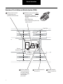
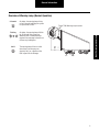
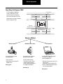
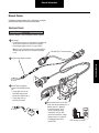
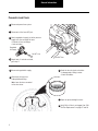
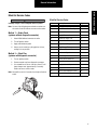
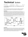
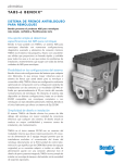
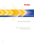
®
Spicer TIMS™ (Tire Inflation and Monitor System) for Trailers
More time on the road®
Troubleshooting Guide
and Service Manual
AXTS0025
January 2007
General Information
Warnings and Cautions
The descriptions and specifications contained in this service
publication are current at the time of printing.
Dana Corporation reserves the right to discontinue or modify
its models and/or procedures and to change specifications at
any time without notice.
Any reference to brand name in this publication is made as an
example of the types of tools and materials recommended for
use and should not be considered an endorsement. Equivalents may be used.
IMPORTANT NOTICE
This symbol is used throughout this
manual to call attention to procedures
where carelessness or failure to follow
specific instructions may result in
personal injury and/or component
damage.
Departure from the instructions, choice
of tools, materials and recommended
parts mentioned in this publication
may jeopardize the personal safety
of the service technician or vehicle
operator.
WARNING: Failure to follow indicated
procedures creates a high risk of personal
injury to the servicing technician.
CAUTION: Failure to follow indicated
procedures may cause component
damage or malfunction.
IMPORTANT: Highly recommended
procedures for proper service of this unit.
Note: Additional service information not
covered in the service procedures.
Tip: Helpful removal and installation
procedures to aid in the service of this unit.
Always use genuine Dana Spicer replacement parts.
Every effort has been made to ensure the accuracy of all information in this guide. However, Dana Commercial Vehicle
Systems Division makes no expressed or implied warranty
or representation based on the enclosed information.
Any errors or omissions may be reported to:
Marketing Services
Dana Commercial Vehicle Systems Division
P.O. Box 4097
Kalamazoo, MI. 49003
Table of Contents
Overview of Tire Inflation and Monitor System (TIMS) .
Overview of Warning Lamp (Normal Operation) . . . . .
Three Ways To Diagnose TIMS . . . . . . . . . . . . . . . . . .
Manual Checks . . . . . . . . . . . . . . . . . . . . . . . . . . .
Blink Out Service Codes . . . . . . . . . . . . . . . . . . . .
PC Diagnostics . . . . . . . . . . . . . . . . . . . . . . . . . . .
Replacement Procedures
1
2
3
4
6
7
Service Codes
Code 11 - Leaking Tire . . . . . . . . . . . . . . . . . . . . . . . . . 8
Code 12 - Tire Pressure Low Reading . . . . . . . . . . . . . 9
Code 14 - Line Leak . . . . . . . . . . . . . . . . . . . . . . . . . . 12
Code 15 - Supply Pressure Low . . . . . . . . . . . . . . . . . 13
Code 16 - Maximum Inflate Time . . . . . . . . . . . . . . . . 15
Code 17 - System Vent Failure . . . . . . . . . . . . . . . . . . 17
Code 21 - Target Out of Range . . . . . . . . . . . . . . . . . . 20
Code 41 - ECU Memory Failure . . . . . . . . . . . . . . . . . 23
Code 43 - No Target Pressure Programmed . . . . . . . 24
Code 44 - No Sensor Signal . . . . . . . . . . . . . . . . . . . . 25
Code 45 - Low Voltage . . . . . . . . . . . . . . . . . . . . . . . . 27
Code 55 - End of Service Code List . . . . . . . . . . . . . . 28
Code 62 - Lamp Shorted . . . . . . . . . . . . . . . . . . . . . . 29
Code 63 - Supply Solenoid Open . . . . . . . . . . . . . . . . 30
Code 64 - Supply Solenoid Shorted . . . . . . . . . . . . . . 31
Code 65 - Control Solenoid Open Circuit . . . . . . . . . . 32
Code 66 - Control Solenoid Shorted . . . . . . . . . . . . . . 33
Tire / Tire Hose . . . . . . . . . . . . . . . . . . . . . . . . . . . . . .35
Hubcap . . . . . . . . . . . . . . . . . . . . . . . . . . . . . . . . . . . .37
Rotary Joint
Drive-In Style . . . . . . . . . . . . . . . . . . . . . . . . . . . .38
Push-In Style . . . . . . . . . . . . . . . . . . . . . . . . . . . .39
Spindle Plug . . . . . . . . . . . . . . . . . . . . . . . . . . . . . . . .41
Axle Hose . . . . . . . . . . . . . . . . . . . . . . . . . . . . . . . . . . .42
Axle Vent Installation . . . . . . . . . . . . . . . . . . . . . . . . . .43
Pneumatic Control Unit (PCU) . . . . . . . . . . . . . . . . . . .45
Electronic Control Unit (ECU)
TIMS . . . . . . . . . . . . . . . . . . . . . . . . . . . . . . . . . . .47
Bendix TABS6 ECU . . . . . . . . . . . . . . . . . . . . . . . .47
Pressure Sensor . . . . . . . . . . . . . . . . . . . . . . . . . . . . .49
Wire Harness
TIMS . . . . . . . . . . . . . . . . . . . . . . . . . . . . . . . . . . .51
Bendix TABS6 ECU . . . . . . . . . . . . . . . . . . . . . . . .53
Service Procedures
Setting Tire Pressure Target . . . . . . . . . . . . . . . . . . . .55
System Learn Method . . . . . . . . . . . . . . . . . . . . .55
Service Tool Method . . . . . . . . . . . . . . . . . . . . . . .56
PCU Air Filter Replacement
Injection Molded Body . . . . . . . . . . . . . . . . . . . . .57
Aluminum Body . . . . . . . . . . . . . . . . . . . . . . . . . .58
Wire Harness
Electrical Schematic . . . . . . . . . . . . . . . . . . . . . . . . . . .59
i
Table of Contents
General Information
General Information
Overview of Tire Inflation and Monitor System (TIMS)
1 Air flows from the air tank
through the pressure
protection valve to the PCU.
2 ECU/PCU controls system without
constant pressure.
• Automatically inflates tires.
• Rechecks tire pressure every 10
minutes.
• Stores data history.
• Turns on Warning Lamp when tires
significantly low.
Check Valve
Rotary Seal
Air
Tank
ECU
PCU
Pressure
Protection Valve
Only
Continuously
Pressurized Line
3 Air flows through air
lines and rotary seals
only when checking
or inflating tires. Axle
tubes are never
pressurized.
1
4 Check valves prevent tire
pressure loss.
5 Axle tube vented to
prevent any pressure
buildup.
General Information
Overview of Warning Lamp (Normal Operation)
2 Seconds
Flashing
Typical TIMS Warning Lamp Location
At startup, the warning lamp will blink
for 45 seconds if the system has
detected a fault. Troubleshooting is
required. See next page to choose one
of three ways to diagnose.
Overview of Warning Lamp
Solid
At startup, the warning lamp will stay
on for 2 seconds indicating the system
has passed the self test.
The warning lamp will turn on solid
when there is low tire pressure
(typically 10%), or a significent line
leak. Inspect tires for damage.
2
General Information
Three Ways To Diagnose TIMS
The Tire Inflation and Monitor
System (TIMS) does not use
continuous pressure; therefore,
leaks cannot be heard at all times.
Check Valves
Rotary Seals
Choose from one of the 3 methods
below to diagnose TIMS.
Air
Tank
ECU
PCU
Pressure
Protection Valve
Only Continuously
Pressurized Line
Choose a Method
Manual Checks
Blink Out Service Codes
Use simple checks to locate
possible problems.
Use warning lamp flashes to
determine service codes.
• Verify electrical.
• Hook up pressure to allow for
audible check.
• Follow troubleshooting
flowcharts for each service
code to pinpoint problem.
• Follow service procedures to
fix diagnosed problems.
Go to page 4.
PC Diagnostics
Use PC and free Dana Diagnostic
Tool (DDT) available on
www.roadranger.com.
• Retrieve historical data, faults, and
tire pressures.
• Pressurize system to detect leaks.
• Access troubleshooting flowcharts
and service procedures.
Go to page 6.
Go to page 7.
3
General Information
Manual Checks
To diagnose trouble without a PC or blink codes, complete
both Electrical Check and Pneumatic Leak Check.
Electrical Check
CAUTION
A battery charger is not an adequate source of power.
1 At startup:
• If warning lamp turns on, then electrical components
are OK. Go to Pneumatic Leak Check on page 5.
• If warning lamp does not turn on, go to step 2.
Note: On newly installed systems or replaced ECUs,
warning lamp will remain on until pressure target
is set.
5-Pin ABS Pass-Thru Connectors
2 Remove lamp bullet connector.
Manual Checks
To Lamp
3 Verify lamp by applying
power to male bullet connector.
• If lamp does not turn on,
check bulb and ground
connection. Repeat step 1.
• If lamp does turn on,
continue with step 4.
To Lamp
4 Remove wire harness from ECU.
Verify wire harness between pin 3
(power) and pin 7 (ground).
• If no power exists, verify
1
12
2
11
trailer is powered, check
3
10
4
9
connections at 5-pin ABS
5
8
pass-thru connectors, and/or
6
7
replace harness as required.
• If adequate power exists,
ECU Harness Connector
replace ECU.
4
General Information
Pneumatic Leak Check
1 Disconnect power from system.
2 Disconnect air line from OUT port.
3 Attach regulated air supply (set to tire pressure
target) to air line and check for leaks:
• External air lines and fittings.
• Axle vent tubes.
IN
OU
Regulated
Air Supply
T
Air OUT Line
4 Repair leaks. If no leaks are found,
go to step 5.
5 Disconnect regulated air supply.
Air OUT Line
7 Check tire hose for check valve leaks:
• Submerge end of fitting in water.
• Check for bubbles.
6 Disconnect tire hose from
hubcap bulkhead fitting.
Note: Leave tire hose connected
to tire valve stems.
8 Repair or replace leaking tire hoses.
9 Verify PCU air filter is not clogged. See “PCU
Air Filter Replacement” on pages 57 and 58.
5
General Information
Blink Out Service Codes
Blink Out Service Codes
Blink Out Service Codes
CAUTION
A battery charger is not an adequate source of power.
Code
Description
Page
Note: Use one of the following two methods to activate service codes. Code 55 indicates no more service codes.
11
Leaking Tire
8
12
Tire Pressure Low Reading
9
Method 1 — Brake Check
(systems without diagnostic connector)
14
Line Leak
12
15
Supply Pressure Low
13
1.
Attach J560 bulkhead connector to trailer.
16
Maximum Inflate Time
15
2.
Turn off ignition switch.
17
System Vent Failure
17
3.
Apply and hold brake pedal.
21
Target Out of Range
20
4.
Access service codes by cycling ignition 3 times,
ending in the on position.
41
ECU Memory Failure
23
43
No Target Pressure Programmed
24
44
No Sensor Signal
25
45
Low Voltage
27
Method 2 — Short Pins
(systems with diagnostic connector)
1.
Turn on ignition switch.
55
End of Service Code List
28
2.
Remove weather cap from diagnostic connector.
62
Lamp Shorted
29
3.
Use screwdriver or coin to short pins A and E until
lamp changes state (approximately 5 seconds).
Release to access service codes.
63
Supply Solenoid Open
30
64
Supply Solenoid Shorted
31
65
Control Solenoid Open Circuit
32
66
Control Solenoid Shorted
33
Note: Lamp will turn on for 5 seconds, then begin to flash out
codes.
F
B
A
E
D
C
6
General Information
PC Diagnostics
To use this program, an RP1210A compatible interface box
and cables are needed to connect the PC to the vehicle.
CAUTION
A battery charger is not an adequate source of power.
Visit www.roadranger.com for free download of Dana Diagnostic Tool (DDT).
PC diagnostics are easy to use and provide the quickest
diagnostic capabilities.
•
Retrieve historical data, faults and tire pressures.
•
Pressurize system to detect leaks.
•
Access troubleshooting flowcharts and service
procedures.
For these types of interface boxes to work with the Dana
Diagnostic Tool program, you must install a "RP1210 driver"
program provided by the manufacturer of the interface box.
If you do not have this program, it can normally be obtained
from the manufacturer's web site. Please contact the
manufacturer of your interface box if you have any questions
regarding this process.
Connect to diagnostic
connector.
Attach computer to RP1210A
communications box.
Download free Dana Diagnostic
Tool from roadranger.com.
Note: Program requires
Windows 98 or newer.
Follow on-screen
instructions.
7
Service Codes
Code 11 - Leaking Tire
Summary
Code 11 is set when the system repeatedly
inflates a low tire. This is typically caused by
a slow leak in a tire, wheel assembly, or tire
hose. If the trailer is left unpowered for an
extended period of time, tire will leak down.
Inspect tires for damage or slow leaks. Check
tire hoses for loose fittings at valve stems.
Leaking tire or
loose tire hose?
Yes
Repair as required.
Clear leaking tire counter and retest
system for proper operation. *
No
Code 11
Test for check valve leaks:
Disconnect power from trailer.
Disconnect control line at OUT port of PCU.
Place end of control line in a cup of water
and watch for bubbles.
Air leaking from
control line?
Manually check each tire to determine if
any one tire is lower than the other tires.
No
Yes
Locate leaking check valve:
Leave tire hoses connected to tire valve stems.
Remove tire hoses one at a time from hubcap fitting.
Place hose fitting in a cup of water and watch for bubbles.
Check low tire and wheel assembly for leakage
and or damage. Repair as necessary.
Clear leaking tire counter and retest
system for proper operation. *
Air
leaking from tire hose
assembly?
No
Repeat on remaining wheel
ends until leak is found.
Yes
Repair or replace tire hose assembly.
Clear leaking tire counter and retest
system for proper operation. *
* To clear the leaking tire service code:
If using a diagnostic tool, follow the instructions provided with the tool.
If not using a diagnostic tool:
- Short pins E and A on the diagnostic connector for greater than 10 seconds.
OR
- Apply constant brake signal (step on brake) and cycle the ignition 5 times,
ending in the on position.
8
Service Codes
Code 12 - Tire Pressure Low Reading
Summary
Code 12 is set when the system reads tire
pressure more than 10% (typical) low. The
most likely cause is a low tire. A secondary
cause may be a significant control line leak.
Inspect for damaged tires. See Pressure
Check below.
Check tire hoses for leaking fittings at
valve stems. See Leak Check Tips below.
Damaged tires or
loose fittings?
Yes
No
Repair as required.
Clear historical codes and retest
system for proper operation.
Remove power. Manually check each
tire for low pressure.
Is tire
pressure low?
Yes
Locate leaking check valve:
Leave tire hoses connected to tire valve stems.
Remove tire hoses one at a time from hubcap fitting.
Place hose fitting in a cup of water and watch for
bubbles.
No
Connect power and air source to trailer.
Inspect lines, fittings, axle components for
large leaks. See Leak Check Tips below.
Air
leaking from tire hose
assembly?
No
Repeat on remaining wheel ends
until leak is found.
Yes
Repair or replace tire hose assembly.
Clear historical codes and retest
system for proper operation.
A
Leak Check Tips
External Lines and Fittings:
Diagnose with a soap and water solution sprayed
on them while the system is pressurized.
Pressure Check
Use the Diagnostic Tool to initiate a pressure check and hold.
If not using the Diagnostic Tool:
- Reduce the tire pressure of one tire by 5 psi.
- Allow the system to re-inflate the tire.
- Check for leaks during the inflation.
9
Internal Axle Components:
Dip axle vent tubes in a container of water.
Inspect for bubbles.
Note: The presence of bubbles indicates an internal
air leak from a failed connection, rotary joint, etc.
Service Codes
Code 12 - Tire Pressure Low Reading (cont’d.)
A
Are there leaks?
Yes
Repair as required.
Clear historical codes and retest
system for proper operation.
Repair as required.
Clear historical codes and retest
system for proper operation.
No
Check for blockage:
PCU filter
Supply line (including pressure protection valve)
from the air source to the IN port on PCU.
Is the line or filter blocked?
Yes
No
Verify the wire harness is plugged into
the pressure sensor on the PCU.
Code 12
Remove power from trailer.
Disconnect TIMS wiring harness at ECU and pressure sensor.
Inspect wire harness for obvious corrosion or damage.
Check for open circuits between any of the
following pairs of terminals:
Is the integrated
controller a Bendix
TABS6?
Yes
Bendix TABS6 ECU
Harness Connector
13
7
1
Pressure Sensor
Harness Connector
A
B
C
No
Check for open circuits between any of the
following pairs of terminals:
Dana ECU Harness
Connector
2
1
6
Pressure Sensor
Harness Connector
A
B
C
Are any
measurements
open?
Yes
Repair or
replace wiring
as required.
Clear historical codes
and retest system for
proper operation.
No
B
10
Service Codes
Code 12 - Tire Pressure Low Reading (cont’d.)
B
Check for short circuits between any of the
following pairs of terminals:
Pressure Sensor
Harness Connector
B
C
A
Pressure Sensor
Harness Connector
A
B
C
Are any
measurements
shorted?
Yes
Repair or replace
wiring as required.
Clear historical codes and retest
system for proper operation.
No
Replace pressure sensor and
retest for proper operation.
Does fault occur again?
No
Complete
Yes
Check air line plumbing lengths per
installation guide AXIG-0025.
Are the control line
lengths as specified?
No
Replumb as required to
specifications.
Yes
Replace PCU.
Does fault occur again?
Yes
Replace ECU and set tire pressure target. See
“Setting Tire Pressure Target.”
Retest system for proper operation.
11
No
Complete
Clear historical codes and retest
system for proper operation.
Service Codes
Code 14 - Line Leak
If service code 12 is active,
troubleshoot it first.
Code 14
Summary
Code 14 is set when the system detects a
significant drop in control line pressure. This
is typically caused by a control line leak
between the PCU and wheel end, including
the rotary joint. A secondary cause may be
a very low tire.
Connect power and air.
Pressurize the air lines. See Pressure Check below.
Inspect lines, fittings and axle components for
leakage. See Leak Check Tips below.
Leakage?
Yes
Repair as required.
Clear historical codes and retest
system for proper operation.
Yes
Repair as required.
Clear historical codes and retest
system for proper operation.
Replace PCU.
Clear historical codes and retest
system for proper operation.
No
Check for crushed or
kinked control lines.
Restriction?
No
Check PCU for leakage at
exhaust port while inflating.
Leakage?
Yes
No
Clear historical codes and retest
system for proper operation.
Leak Check Tips
External Lines and Fittings:
Diagnose with a soap and water solution sprayed
on them while the system is pressurized.
Pressure Check
Use the Diagnostic Tool to initiate a pressure check and hold.
If not using the Diagnostic Tool:
- Reduce the tire pressure of one tire by 5 psi.
- Allow the system to re-inflate the tire.
- Check for leaks during the inflation.
Internal Axle Components:
Dip axle vent tubes in a container of water.
Inspect for bubbles.
Note: The presence of bubbles indicates an internal
air leak from a failed connection, rotary joint, etc.
12
Service Codes
Code 15 - Supply Pressure Low
Summary
Code 15 is set when the system is powered
and has not sensed adequate supply pressure
for an extended period of time. See the lists
below for other possible causes.
If service code 44 is active,
troubleshoot it first.
Verify that air supply pressure at PCU is
greater than the tire target pressure. See
Pressure Check and Leak Check Tip below.
Adequate supply pressure?
No
Repair as required.
Clear historical codes and retest
system for proper operation.
Yes
Check for audible
leakage at the PCU vent.
Are there leaks?
Yes
Replace PCU.
Clear historical codes and retest
system for proper operation.
No
Verify the wire harness is plugged into the
pressure sensor on the PCU.
Remove power from trailer.
Disconnect TIMS wiring harness at ECU and pressure sensor.
Inspect wire harness for obvious corrosion or damage.
A
Pressure Check
Use the Diagnostic Tool to initiate a pressure check and hold.
If not using the Diagnostic Tool:
- Reduce the tire pressure of one tire by 5 psi.
- Allow the system to re-inflate the tire.
- Check for leaks during the inflation.
13
Leak Check Tip
External Lines and Fittings:
Diagnose with a soap and water solution sprayed
on them while the system is pressurized.
Service Codes
Code 15 - Supply Pressure Low (cont’d.)
A
Check for open circuits between any of the
following pairs of terminals:
Is the integrated
controller a Bendix
TABS6?
Yes
Bendix TABS6 ECU
Harness Connector
13
7
1
Pressure Sensor
Harness Connector
A
B
C
No
Dana ECU Harness
Connector
2
1
6
Pressure Sensor
Harness Connector
A
B
C
Are any
measurements
open?
Yes
Repair or
replace wiring
as required.
Clear historical codes
and retest system for
proper operation.
Repair or
replace wiring
as required.
Clear historical codes
and retest system for
proper operation.
Code 15
Check for open circuits between any of the
following pairs of terminals:
No
Check for short circuits between any of the
following pairs of terminals:
Pressure Sensor
Harness Connector
B
C
A
Pressure Sensor
Harness Connector
A
B
C
Are any
measurements
shorted?
Yes
No
Replace pressure sensor and
retest for proper operation.
Does fault occur again?
No
Complete
Yes
Replace ECU and set tire pressure target. See
“Setting Tire Pressure Target.”
Retest system for proper operation.
14
Service Codes
Code 16 - Maximum Inflate Time
Summary
Code 16 is set when the system has inflated
for an extended period of time without
successfully reaching target pressure. The
system will continue to attempt to maintain
tire pressure after this code is set. The most
likely cause is a leaking tire or air line.
If service code 12 is
active, troubleshoot it first.
Connect power and air.
Pressurize the air lines. See Pressure Check below.
Inspect lines, fittings and axle components for
leakage. See Leak Check Tips below.
Leakage?
Yes
Repair as necessary.
Clear historical codes and retest
system for proper operation.
No
Check for crushed or kinked control lines.
Restriction?
Yes
Repair as necessary.
Clear historical codes and retest
system for proper operation.
No
Check PCU for leakage at
exhaust port while inflating.
Leakage?
Yes
Replace PCU.
Clear historical codes and retest
system for proper operation.
No
Verify the wire harness is plugged into
the pressure sensor on the PCU.
A
Pressure Check
Use the Diagnostic Tool to initiate a pressure check and hold.
If not using the Diagnostic Tool:
- Reduce the tire pressure of one tire by 5 psi.
- Allow the system to re-inflate the tire.
- Check for leaks during the inflation.
15
Leak Check Tips
External Lines and Fittings:
Diagnose with a soap and water solution sprayed
on them while the system is pressurized.
Internal Axle Components:
Dip axle vent tubes in a container of water.
Inspect for bubbles.
Note: The presence of bubbles indicates an internal
air leak from a failed connection, rotary joint, etc.
Service Codes
Code 16 - Maximum Inflate Time (cont’d.)
A
Remove power from trailer.
Disconnect TIMS wiring harness at ECU and pressure sensor.
Inspect wire harness for obvious corrosion or damage.
Check for open circuits between any of the
following pairs of terminals:
Is the integrated
controller a Bendix
TABS6?
Yes
Bendix TABS6 ECU
Harness Connector
13
7
1
Pressure Sensor
Harness Connector
A
B
C
No
Check for open circuits between any of the
following pairs of terminals:
Dana ECU Harness
Connector
2
1
6
Pressure Sensor
Harness Connector
A
B
C
Are any
measurements
open?
Yes
Repair or
replace wiring
as required.
Clear historical codes
and retest system for
proper operation.
Repair or
replace wiring
as required.
Clear historical codes
and retest system for
proper operation.
No
Check for short circuits between any of the
following pairs of terminals:
Code 16
Pressure Sensor
Harness Connector
B
C
A
Pressure Sensor
Harness Connector
A
B
C
Are any
measurements
shorted?
Yes
No
Replace pressure sensor and
retest for proper operation.
Does fault
occur again?
No
Complete
Yes
Replace ECU and set tire pressure target. See
“Setting Tire Pressure Target.”
Retest system for proper operation.
16
Service Codes
Code 17 - System Vent Failure
Summary
Code 17 is set when the system detects
that the control lines did not depressurize
(vent) correctly. This is typically caused by
a contaminated or faulty check valve in a
tire hose.
To verify PCU exhaust is not blocked:
Connect air and power.
Listen for burst of air at PCU exhaust when system vents.
System will vent either when the pressure check completes OR
when power is removed.
Audible vent?
Note: This code can result from incorrect
ECU/wiring harness combination. To verify
compatibility, check Illustrated Parts List
AXIP0025.
Inspect PCU exhaust for
contamination, undercoating,
paint, ice, etc.
No
Yes
Contaminates
found?
No
Yes
Test for check valve leaks:
Disconnect power from trailer.
Disconnect control line at OUT port of PCU and place end
of control line in a cup of water and watch for bubbles.
Clean as necessary.
Clear historical codes and retest
system for proper operation.
Air leaking from
control line?
A
No
Yes
Locate leaking check valve:
Leave tire hoses connected to tire valve stems.
Remove tire hoses one at a time from hubcap fitting.
Place hose fitting in a cup of water and watch for bubbles.
Air
leaking from tire hose
assembly?
Yes
Repair or replace tire
hose assembly.
Clear historical codes and retest
system for proper operation.
17
No
Repeat on remaining wheel
ends until leak is found.
Service Codes
Code 17 - System Vent Failure (cont’d.)
Code 17
A
Verify the wire harness is plugged into
the pressure sensor on the PCU.
Remove power from trailer.
Disconnect TIMS wiring harness at ECU and pressure sensor.
Inspect wire harness for obvious corrosion or damage.
Check for open circuits between any of the
following pairs of terminals:
Is the integrated
controller a Bendix
TABS6?
Yes
Bendix TABS6 ECU
Harness Connector
13
7
1
Pressure Sensor
Harness Connector
A
B
C
No
Check for open circuits between any of the
following pairs of terminals:
Dana ECU Harness
Connector
2
1
6
Pressure Sensor
Harness Connector
A
B
C
Are any
measurements
open?
Yes
Repair or
replace wiring
as required.
Clear historical codes
and retest system for
proper operation.
Repair or
replace wiring
as required.
Clear historical codes
and retest system for
proper operation.
No
Check for short circuits between any of the
following pairs of terminals:
Pressure Sensor
Harness Connector
B
C
A
Pressure Sensor
Harness Connector
A
B
C
Are any
measurements
shorted?
Yes
No
B
18
Service Codes
Code 17 - System Vent Failure (cont’d.)
B
Replace pressure sensor and
retest for proper operation.
Does fault
occur again?
No
Complete
Yes
Check air line plumbing lengths
per installation guide AXIG-0025.
Are the control line
lengths as specified?
No
Replumb as necessary
to specifications.
Yes
Clear historical codes and retest
system for proper operation.
Replace PCU.
Does fault
occur again?
No
Yes
Replace ECU and set tire pressure target. See
“Setting Tire Pressure Target.”
19
Complete
Clear historical codes and retest
system for proper operation.
Service Codes
Code 21 - Target Out of Range
Summary
Code 21 is set when the Target Learn Method
is used and the system senses tire pressure(s)
out of the acceptable target range (typically 80125 psi). “See Setting Tire Pressure Target.”
Verify tire pressures are within acceptable target range
[typically 80-125 psi]. See Pressure Check below .
Yes
Repair as required and inflate to
desired tire pressure target.
Follow the “Setting Tire Pressure
Target” procedure to set tire target
pressure in ECU.
Yes
Repair as required and inflate to
desired tire pressure target.
Follow the “Setting Tire Pressure
Target” procedure to set tire target
pressure in ECU.
Repair or replace damaged or
restricted lines as required.
Follow the “Setting Tire Pressure
Target” procedure to set tire target
pressure in ECU.
Code 21
Is any tire
below minimum target pressure of
80 psi?
Note: The system will read the pressure of the
lowest tire; one or more tire pressures below
the minimum target will set this code.
No
Are all tires
above maximum target pressure
of 125 psi?
No
Check control lines blockage,
restrictions, or kinks.
Verify the wire harness is plugged into
the pressure sensor on the PCU.
Remove power from trailer.
Disconnect TIMS wiring harness at ECU and pressure sensor.
Inspect wire harness for obvious corrosion or damage.
A
Pressure Check
Use the Diagnostic Tool to initiate a pressure check and hold.
If not using the Diagnostic Tool:
- Reduce the tire pressure of one tire by 5 psi.
- Allow the system to re-inflate the tire.
- Check for leaks during the inflation.
20
Service Codes
Code 21 - Target Out of Range (cont’d.)
A
Check for open circuits between any of the
following pairs of terminals:
Is the integrated
controller a Bendix
TABS6?
Yes
Bendix TABS6 ECU
Harness Connector
13
7
1
Pressure Sensor
Harness Connector
A
B
C
No
Check for open circuits between any of the
following pairs of terminals:
Dana ECU Harness
Connector
2
1
6
Pressure Sensor
Harness Connector
A
B
C
Are any
measurements
open?
Yes
Repair or
replace wiring
as required.
Clear historical codes
and retest system for
proper operation.
Repair or
replace wiring
as required.
Clear historical codes
and retest system for
proper operation.
No
Check for short circuits between any of the
following pairs of terminals:
Pressure Sensor
Harness Connector
B
C
A
Pressure Sensor
Harness Connector
A
B
C
Are any
measurements
shorted?
Yes
No
Replace pressure sensor and
retest for proper operation.
Does fault occur again?
Yes
B
21
No
Complete
Service Codes
Code 21 - Target Out of Range (cont’d.)
B
Replace PCU and retest for proper operation.
Does fault occur again?
No
Complete
Code 21
Yes
Replace ECU and set tire pressure target. See
“Setting Tire Pressure Target.”
Complete
22
Service Codes
Code 41 - ECU Memory Failure
Summary
Code 41 is set when the ECU memory has
been corrupted. The ECU may have reset to
its defaults and lost historical data and/or its
tire pressure target.
If service code 43 is active, reset
tire pressure target. See “Setting
Tire Pressure Target.”
Retest system for proper operation.
Does fault
reoccur?
No
Yes
Replace ECU and set tire pressure target. See
“Setting Tire Pressure Target.”
Retest system for proper operation.
23
Complete
Service Codes
Code 43 - No Target Pressure Programmed
If other service codes are active,
troubleshoot them first.
Summary
Code 43 is set when no tire pressure target
has been set in the ECU. The tire pressure
target can be set using a diagnostic tool, or
through the Target Learn Method. See
“Setting Tire Pressure Target.”
Replace ECU and set tire pressure target. See
“Setting Tire Pressure Target.”
Codes 41, 43
24
Service Codes
Code 44 - No Sensor Signal
Summary
Code 44 is set when the ECU does not detect
a pressure sensor signal. The most likely
cause is a disconnected pressure sensor or
faulty wiring.
Verify the wire harness is plugged into
the pressure sensor on the PCU.
Remove power from trailer.
Disconnect TIMS wiring harness at ECU and pressure sensor.
Inspect wire harness for obvious corrosion or damage.
Check for open circuits between any of the
following pairs of terminals:
Is the integrated
controller a Bendix
TABS6?
Yes
Bendix TABS6 ECU
Harness Connector
13
7
1
Pressure Sensor
Harness Connector
A
B
C
No
Check for open circuits between any of the
following pairs of terminals:
Dana ECU Harness
Connector
2
1
6
Pressure Sensor
Harness Connector
A
B
C
Are any
measurements
open?
Yes
No
Check for short circuits between any of the
following pairs of terminals:
Pressure Sensor
Harness Connector
B
C
A
Pressure Sensor
Harness Connector
A
B
C
A
25
Repair or
replace wiring
as required.
Clear historical codes
and retest system for
proper operation.
Service Codes
Code 44 - No Sensor Signal (cont’d.)
Are any
measurements
shorted?
Code 44
A
Yes
Repair or replace
wiring as required.
Clear historical codes and retest
system for proper operation.
No
Replace pressure sensor and
retest for proper operation.
Does fault occur
again?
No
Complete
Yes
Replace ECU and set tire pressure target. See
“Setting Tire Pressure Target.”
Retest system for proper operation.
26
Service Codes
Code 45 - Low Voltage
CAUTION
A battery charger is not an adequate source of power.
Summary
Code 45 is set when the ECU senses the
voltage is too low to properly turn the PCU
solenoids on.
Verify trailer is properly
powered (minimum 9 volts).
Remove power from trailer.
Disconnect TIMS wiring harness at ECU.
Inspect wire harness for obvious corrosion or damage.
Apply power to trailer.
Measure voltage between ECU harness
connector pin 3 (power) and pin 7 (ground).
Is the voltage
> 9 volts?
Yes
No
Check connections at ABS 5-pin pass-through
connectors and/or replace harness as required.
27
Replace ECU and set tire pressure target.
See “Setting Tire Pressure Target.”
Service Codes
Code 55 - End of Service Code List
Summary
Code 55 indicates the end of the service code
list when blinking out the codes. If only a 55
is blinked out, there are no active codes.
Codes 45, 55
28
Service Codes
Code 62 - Lamp Shorted
Summary
Code 62 is set when the system detects a
short in the warning lamp circuit. This is
typically the result of faulty lamp wiring.
Disconnect lamp wire at bullet connector
on TIMS harness near ABS connector.
Cycle power and check service codes
with diagnostic tool.
Is
service code 62
still active?
No
Repair or replace damaged
bullet-to-lamp wiring or
lamp as required.
Clear historical codes and retest
system for proper operation.
Yes
Is the integrated
controller a Bendix
TABS6?
Yes
Disconnect harness from ECU.
Check for short circuit between
terminal 2 and ground.
No
Disconnect power from trailer.
Disconnect harness from ECU.
Check for short circuit between
terminal 10 and ground.
Is the
circuit shorted?
Yes
No
Replace ECU and set tire pressure target. See
“Setting Tire Pressure Target.”
Retest system for proper operation.
29
Repair or replace
damaged harness
as required.
Clear historical codes
and retest system for
proper operation.
Service Codes
Code 63 - Supply Solenoid Open
Summary
Code 63 is set when an open in the PCU
supply solenoid or associated wiring is
detected. This is typically the result of an
unplugged solenoid connector or faulty wiring.
Verify PCU solenoid connector is properly connected.
Disconnect power from trailer.
Disconnect harness from PCU solenoids.
Check for open circuit at PCU solenoids,
terminals A and B.
Is the
solenoid
open?
Yes
Clear historical codes and retest
system for proper operation.
Replace PCU.
No
Remove power from trailer.
Disconnect TIMS wiring harness at ECU and PCU.
Inspect wire harness for obvious corrosion or damage.
Codes 62, 63
Check for open circuit between the following terminals:
Is the integrated
controller a Bendix
TABS6?
Yes
Disconnect harness
from ECU and PCU.
Bendix TABS6 ECU
Harness Connector
15
4
PCU
Harness Connector
A
B
No
Check for open circuits between any of the
following pairs of terminals:
Dana ECU Harness
Connector
8
3
PCU Harness
Connector
A
B
Is either
measurement
open?
Yes
Repair or replace
damaged harness
as required.
Clear historical codes
and retest system for
proper operation.
No
Replace ECU and set tire pressure target. See
“Setting Tire Pressure Target.”
Retest system for proper operation.
30
Service Codes
Code 64 - Supply Solenoid Shorted
Disconnect wiring harness at PCU solenoids connector.
Cycle power and check service codes.
Note: This will result in service codes 63 and 65 (open circuit),
which should be ignored.
Is service
code 64 (short circuit) still
active?
No
Summary
Code 64 is set when a short in the PCU supply
solenoid or associated wiring is detected. This
is typically the result of damaged wiring or
connectors.
Replace PCU.
Clear historical codes and retest
system for proper operation.
Repair or replace damaged
harness as required.
Clear historical codes and retest
system for proper operation.
Yes
Disconnect power from trailer.
Disconnect harness from ECU.
Check the wire harness for short circuit between PCU
solenoid connector terminals A and B.
Is
the harness
shorted?
No
Replace ECU and set tire pressure target. See
“Setting Tire Pressure Target.”
Retest system for proper operation.
31
Yes
Service Codes
Code 65 - Control Solenoid Open Circuit
Verify PCU solenoid connector is properly connected
Codes 64, 65
Summary
Code 65 is set when an open in the PCU
control solenoid or associated wiring is
detected. This is typically the result of an
unplugged solenoid connector or faulty wiring.
Disconnect power from trailer.
Disconnect harness from PCU solenoids.
Check for open circuit at PCU solenoids,
terminals A and B.
Is the solenoid open?
Yes
Clear historical codes and retest
system for proper operation.
Replace PCU.
No
Remove power from trailer.
Disconnect TIMS wiring harness at ECU and PCU.
Inspect wire harness for obvious corrosion or damage.
Check for open circuit between the following terminals:
Is the integrated
controller a Bendix
TABS6?
Yes
Disconnect harness
from ECU and PCU.
Bendix TABS6 ECU
Harness Connector
4
10
PCU
Harness Connector
B
C
No
Check for open circuits between any of the
following pairs of terminals:
Dana ECU Harness
Connector
3
11
PCU Harness
Connector
B
C
Is either
measurement
open?
Yes
Repair or replace
damaged harness
as required.
Clear historical codes
and retest system for
proper operation.
No
Replace ECU and set tire pressure target. See
“Setting Tire Pressure Target.”
Retest system for proper operation.
32
Service Codes
Code 66 - Control Solenoid Shorted
Disconnect wiring harness at PCU solenoids connector.
Cycle power and check service codes.
Note: This will result in service codes 63 and 65 (open circuit),
which should be ignored.
Is service
code 66 (short circuit) still
active?
No
Summary
Code 66 is set when a short in the PCU control
solenoid or associated wiring is detected. This
is typically the result of damaged wiring or
connectors.
Replace PCU.
Clear historical codes and retest
system for proper operation.
Repair or replace damaged
harness as required.
Clear historical codes and retest
system for proper operation.
Yes
Disconnect power from trailer.
Disconnect harness from ECU.
Check wire harness for short circuit between PCU
solenoid connector terminals B and C.
Is the
harness shorted?
No
Replace ECU and set tire pressure target. See
“Setting Tire Pressure Target.”
Retest system for proper operation.
33
Yes
Service Codes
This page intentionally left blank.
Code 66
34
Replacement Procedures
Tire / Tire Hose
Removal
Installation
Disconnect power from trailer during tire removal to eliminate
potential faults if the system attempts to check tire pressures
while the tire hoses are detached.
1.
Disconnect tire hose T from bulkhead fitting at hubcap.
2.
Disconnect tire hose from valve stems.
Note: There will be no tire pressure air loss since a check
valve is located in the tire hoses.
35
3.
Cover (plug) the hubcap fitting to prevent contamination from entering the system.
4.
Observe and record the orientation of the wheel to
the hub before removal of the wheel (see below).
5.
Remove wheel.
1.
Reinstall the wheel. Take care not to damage the
hubcap fitting. Make sure the wheel is properly oriented to the hub as recorded in Removal step 4.
2.
Reinstall inner tire hose at valve system if previously
removed. Tighten with fingers.
3.
Reinstall outer tire hose and finger-tighten.
4.
Tighten the inverted flare nut finger tight. Tighten
with a wrench an additional 1/4 turn.
5.
Power up trailer and check hoses for leaks.
CAUTION
Do not over tighten. Using pliers to tighten the tire hoses to
the valve stem or T assembly may damage the gasket causing a leak. Ensure tire hoses are NOT stretched or rubbing
on the wheel or hub.
Clock A
Clock B
Clock C
5-Hole Wheel Installation
(17.5" or 22.5" Wheel)
5-Hole Wheel Installation
(19.5" or 24.5" Wheel)
2-Hole Wheel Installation
(any size Wheel)
Replacement Procedures
Check Valve at Valve Stem
90˚ Fitting for Super Singles
Check
Valve
OR
Outer Wheel Hose
Assembly
T Fitting
For Duals
Inner Wheel Hose
Assembly
Check
Valve
Tire / Tire Hose
Check Valve at T Fitting
90˚ Fitting for Super Singles
Check
Valve
OR
Check
Valve
Outer Wheel Hose
Assembly
T Fitting
For Duals
Inner Wheel Hose
Assembly
36
Replacement Procedures
Hubcap
Removal
Installation
When a service event occurs that requires the removal of the
hub, care must be taken to avoid damaging the TIMS rotary
joint assembly:
•
•
On P series wheel ends (axles with same size inner
and outer bearings), the hub may be removed with
the rotary joint in place. Follow service procedure for
tire removal. Remove the jam nut from the rotary
joint's bulkhead adapter and remove the hubcap.
Remove the hub in the standard manner.
On all other types of wheel ends, the rotary joint
must be removed for the hub and bearings to clear
the TIMS rotary joint assembly. Follow service procedure for tire removal, then follow “Rotary Joint Push-In Style” on page 39.
Bulkhead
Adapter
37
Place hubcap gasket over rotary joint’s exit tube and
bulkhead adapter.
2.
Lubricate O-ring on the rotary joint’s bulkhead
adapter.
3.
From the inside, insert the bulkhead adapter through
the hole in the hubcap marked “Air.” Attach the jam
nut and hand-tighten.
CAUTION
Wheel must be properly “clocked” to hubcap to prevent
hoses rubbing on the wheel. Failure to do so may result in
hose failure.
4.
Spindle
Jam Nut
Hubcap
1.
Rotary Joint
Assembly
Braided Hose
Align the hubcap and gasket and install the 6 bolts.
Torque to the values listed in the chart per manufacturers’ recommendations.
Hub Material
Bolt Grade
Bolt Size
Torque
Iron
5
5/16-18
16-19 lbs. ft.
Iron
8
5/16-18
22-27 lbs. ft.
Aluminum
5&8
5/16-18
10-12 lbs. ft.
5.
Torque the bulkhead adapter jam nut to 25 lbs. ft.
6.
Refill hubcap with proper lubricant.
7.
Refer to tire hose installation to complete reassembly. See “Tire / Tire Hose” on page 35.
8.
Power up trailer and check for leaks.
Replacement Procedures
Removal
Installation
See “Tire / Tire Hose” on page 35 and “Hubcap” on page 37
for tire hose T and hubcap removal procedures.
1.
2.
Position a chisel at the parting line of the rotary
joint’s flange and the end of the spindle. Strike with
hammer to separate and repeat on the opposite
sides, alternating to evenly remove joint from spindle
bore.
1.
Screw braided hose fitting into back of rotary joint
and seal using paste-type sealer on threads.
2.
Orient rotary joint with TOP marking at top of spindle.
3.
Align driver so that recesses fit over rotary joint fittings and flexible hose, and carefully drive joint into
spindle bore. Ensure that joint is driven in squarely
and that it bottoms in bore so that outer flange is
flush with end of spindle.
Unscrew the braided line fitting from the back of the
rotary joint to complete removal.
Braided
Hose
Rotary Joint
Assembly
Chisel
Rotary Joint
Assembly
Spindle
Driver
38
Rotary Joint-Drive-In Style
Rotary Joint - Drive-In Style
Replacement Procedures
Rotary Joint - Push-In Style
Removal
1.
Remove the jam nut from the rotary joint's bulkhead
adapter and remove the hubcap.
2.
Place two screwdrivers 180 degrees apart with the
blades under the lip of the rubber collar and over the
metal lip of the rotary joint's body.
Installation
1.
Assemble Rubber Collar
a.
See AXIG-0025 for part number information.
b.
Install appropriate rubber collar over flexible
tube from outboard side of rotary joint, aligning
Top Notch on collar with flat on joint.
CAUTION
Make sure the label and part number face out.
Insert Screwdrivers
Under Rubber Collar Lip
Note: Before installing rotary joint assemblies, install hubs
and drums according to manufacturer's specifications.
After installing rotary joint assemblies, a hubcap spacer
may be required if using Pro-Torque nuts.
Top Notch
Flat
T
3.
OP
Push the screwdrivers toward the trailer, prying the
rotary joint assembly out of the spindle bore. The
rotary joint will then be held in place only by the
clamp on the braided hose assembly.
Top Notch
Flat
Pry Rotary Joint
Assembly Out of Spindle
4.
39
Cut the clamp and remove the rotary joint assembly
from the braided hose.
Replacement Procedures
2.
Clamp Axle Hose
a.
Install stepless ear clamp onto end of axle hose.
b.
Push barbed end of rotary joint into end of axle
hose until hose bottoms on the rotary joint
body.
c.
b.
Orient the flat on the rotary joint body (located
near the clamp) to the flat in the hole of the
spindle plug and push the rotary joint assembly
into the axle.
c.
The assembly is seated when the outer lip of the
rubber collar is almost flush with the end of the
spindle.
Use crimping tool (Oetiker® pliers) to squeeze
ear clamp, fastening hose to rotary joint.
TOP
Press ONLY here when
inserting axle end.
Spindle
Cut Clamp
and Remove
4.
Rotary Joint
Assembly
a.
CAUTION
Push only on face of rotary joint where it meets the rubber
collar. Do not use a hammer. Do not push on the brass air
tube.
3.
Verify Proper Installation
Using fingers only, pull firmly straight out on
brass tube at the center of the rotary joint. A
properly installed and seated rotary joint will not
pull out.
Grasp brass colored
tube at center as
illustrated.
Push Assembly Into Axle
a.
Apply lubricant to inside of axle spindle to
ensure proper installation.
Pull firmly straight out to
verify proper installation.
40
Rotary Joint-Push-In Style
Braided
Hose
Cutting Tool
Replacement Procedures
Spindle Plug
Note: Spindle plug is only used with Push-In Style rotary
joints.
Note: The driver regulates the correct installation depth.
4.
Removal
1.
Remove old spindle plug.
Installation
1.
Route the end of the axle hose assembly through the
center of the spindle plug assembly.
2.
With the breather hole of the spindle plug assembly
located in the 12 o’clock position, place the plug
assembly at the spindle end.
3.
Route the braided hose assembly through the slot in
the end of the plug driver and press the plug into the
spindle until the driver bottoms out.
D22 Spindle
5.
Refer to these sections to complete assembly of
wheel end:
•
“Rotary Joint - Push-In Style” on page 39
•
“Hubcap” on page 37
•
“Tire / Tire Hose” on page 35
Power system, pressurize, and check for leaks.
Braided
Hose
D22-Style
Spindle
Spindle Plug
with Small Hole and "Flat"
at 12 O'Clock Position
Plug
Driver Handle
Plug
Driver
P22 Spindle
Spindle Plug
with Small Hole and "Flat"
at 12 O'Clock Position
Plug
Driver Handle
Plug
Driver
41
P22-Style
Spindle
Braided
Hose
Replacement Procedures
Axle Hose
Refer to these sections first:
•
“Tire / Tire Hose” on page 35
•
“Hubcap” on page 37
•
“Rotary Joint - Push-In Style” on page 39
Installation
1.
In the 1/4" pipe hole located in the top of the axle
tube, route the small covered end of the metal
braided hose into the axle.
2.
Make sure the hose is going toward the correct
wheel end and continue feeding the metallic covered
hose into the trailer axle until the small end of the
hose exits the spindle end.
3.
Thread the large adapter end of the axle hose assembly into the axle and tighten to 30 lbs. ft. (27.1 N•m).
4.
Remove protective coverings from end of axle hose
assembly and blow air through it to remove any
debris.
Removal
1.
If internal hose needs to be replaced, remove air fittings from connection on the top of the axle then
remove the hose assembly from the axle.
Axle Hose
Braided
Hose
42
Replacement Procedures
Axle Vent Installation
1.
Locate 1/4" pipe-threaded hole in axle and verify 3/8"
NTA fitting is installed.
2.
Install 45-degree or straight 1/4" NPT male to NTA
fitting.
Note: Do not allow vent hose to dip below NTA fitting on axle.
6.
Note: Use appropriate sealant on threads.
3.
Install vent hose in NPT male.
4.
Route and fasten hose to top of slider assembly.
5.
Loop hose downward in “candy cane” fashion:
Secure hose:
•
Use frame clips, zip-ties or similar device.
•
Fasten open end of hose to main vent line.
•
Verify hose opening points down with no
obstructions.
CAUTION
Do not kink vent hose.
•
Downward leg should drop 10-12".
•
Opening should point down.
•
Hose should have enough slack to prevent damage during suspension travel.
CAUTION
Failure to properly install axle vent hoses may result in
wheel end pressurization and/or water contamination
toward the ground.
Correct Hose Routing
Fasten securely.
Make sure vent
hose opening drops
10-12" below
loop and points
downward.
Incorrect Hose Routing
Make sure slack in
hose allows for
suspension travel.
Do not point
vent hose upward,
which allows
foreign matter
to enter.
Do not let hose:
• Dip below NTA
fitting on axle.
• Extend above
slider assembly.
43
Replacement Procedures
Axle Vent Installation
This page intentionally left blank.
44
Replacement Procedures
Pneumatic Control Unit (PCU)
Note: When replacing Aluminum Body PCU with Injection
Molded Body PCU, a new mounting bracket, part number 676644, is required.
Installation
1.
Install pressure sensor into PCU using paste-type
thread sealant.
Removal
•
Injection Molded Body: Torque to 100 lbs. in.
1.
Disconnect trailer power.
•
Aluminum Body: Torque to 230 lbs. in.
2.
Drain air tank.
WARNING
Drain off supply air tank before removing any fittings.
3.
Disconnect solenoid connector.
4.
Remove plastic PCU cover.
Note: Aluminum Body does not have plastic PCU cover.
45
2.
Aluminum Body Only: Install air line fitting using
paste-type thread sealant.
3.
Install PCU to bracket. Torque to 110 lbs. in.
4.
Connect pressure sensor connector.
5.
Install plastic PCU cover.
Note: Aluminum Body does not have plastic PCU cover.
6.
Connect solenoid connector.
7.
Connect air IN line.
5.
Disconnect pressure sensor connector.
8.
Connect air OUT line.
6.
Disconnect air IN line and mark hose.
9.
7.
Disconnect air OUT line and mark hose.
Test for air leaks at air IN and air OUT locations by
using soapy water.
8.
Unbolt PCU (2 bolts) from bracket.
Note: Air will not leak at OUT location unless system is pressurized.
Replacement Procedures
Injection Molded Body
Pressure Sensor Connector
Pressure Sensor
Pneumatic Control Unit
(PCU)
Air OUT
PCU Cover
Air IN
Mounting Bolt
Solenoid Connector
Aluminum Body
Pressure Sensor Connector
Pressure Sensor
Mounting Bolt
T
OU
Air OUT Fitting
IN
Solenoid Connector
Air IN Fitting
46
Replacement Procedures
Electronic Control Unit (ECU)
CAUTION
When replacing early model ECU part number 676474, the
pressure sensor part numbers 673221 or 676505 (black
connector) must be replaced with pressure sensor part
number 676495 (tan connector).
TIMS - Removal
1.
Disconnect trailer power.
2.
Injection Molded Body Only:
Unbolt PCU (2 bolts) from bracket.
3.
Disconnect ECU connector.
4.
Unbolt ECU (2 bolts) from bracket.
TIMS - Installation
47
1.
Install replacement ECU and torque to 60 lbs. in.
2.
Connect ECU connector.
3.
Injection Molded Body Only:
Reinstall PCU. Torque to 100 lbs. in.
4.
Set tire pressure target. See “Setting Tire Pressure
Target” on page 55.
Bendix TABS6 ECU - Removal
1.
See Bendix Service Manual for instructions on
removing TABS6 ECU.
Bendix TABS6 ECU - Installation
1.
See Bendix Service Manual for instructions on
installing TABS6 ECU.
2.
Set tire pressure target. See “Setting Tire Pressure
Target” on page 55.
Replacement Procedures
Injection Molded Body
ECU
Mounting Bolt
ECU Connector
Electronic Control Unit
(ECU)-TIMS
Mounting Bolt
Aluminum Body
T
OU
Mounting Bolt
IN
ECU
ECU Connector
48
Replacement Procedures
Pressure Sensor
Removal
Installation
1.
Disconnect trailer power.
2.
Drain supply tank.
1.
Apply paste-type thread sealant on replacement
pressure sensor and install.
•
Injection Molded Body: Torque sensor to
100 lbs. in.
•
Aluminum Body: Torque sensor to 230 lbs. in.
WARNING
Drain off supply air tank before removing any fittings.
3.
49
Injection Molded Body Only:
a.
Disconnect solenoid connector.
b.
Remove plastic PCU cover.
4.
Disconnect pressure sensor connector.
5.
Remove old pressure sensor from PCU.
WARNING
Do not use thread sealant tape.
2.
Connect pressure sensor connector.
3.
Injection Molded Body Only:
a.
Install plastic PCU cover.
b.
Connect solenoid connector.
4.
Power up trailer.
5.
Verify warning lamp operation.
Replacement Procedures
Pressure Sensor
Injected Molded Body
Pressure Sensor Connector
Pressure Sensor
PCU Cover
Solenoid Connector
Aluminum Body
Pressure Sensor Connector
Pressure Sensor
T
OU
IN
50
Replacement Procedures
Wire Harness - TIMS
CAUTION
Installation
When replacing early model wire harnesses part numbers
676271, 676272 and 676471 (which do not have an overmolded ECU connector), the ECU must also be replaced.
1.
Connect 5-pin ABS connector.
2.
Connect 5-pin power supply connector.
3.
Connect ECU connector.
Removal
4.
Connect pressure sensor connector.
1.
Disconnect trailer power.
5.
Install plastic PCU cover.
2.
Disconnect 5-pin ABS connector.
3.
Disconnect 5-pin power supply connector.
6.
Connect solenoid connector.
4.
Disconnect ECU connector.
7.
Connect lamp wire bullet connector.
5.
Disconnect solenoid connector.
8.
Bolt diagnostic connector to bracket.
6.
Remove plastic PCU cover.
9.
Secure harness as required (on slider applications,
allow for slider operation).
Note: Aluminum Body does not have plastic PCU cover.
7.
Disconnect pressure sensor connector.
8.
Disconnect lamp wire bullet connector.
9.
Unbolt diagnostic connector from bracket.
10. Cut tie wrap.
51
Note: Aluminum Body does not have plastic PCU cover.
10. Verify warning lamp operation.
Replacement Procedures
Injection Molded Body
Lamp Wire
Bullet Connector
Power Supply
Connector
ABS Connector
Wire Harness-TIMS
Pressure Sensor Connector
PCU Cover
Diagnostic Connector
Solenoid Connector
ECU Connector
Aluminum Body
Lamp Wire Bullet Connector
Power Supply
Connector
ABS Connector
Pressure Sensor
Connector
Diagnostic Connector
T
OU
IN
Solenoid Connector
ECU Connector
52
Replacement Procedures
Wire Harness - Bendix TABS6 ECU
Removal
Installation
1.
Disconnect trailer power.
1.
Connect pressure sensor connector.
2.
Disconnect solenoid connector.
2.
Install plastic PCU cover.
3.
Remove plastic PCU cover.
3.
Connect solenoid connector.
4.
Disconnect pressure sensor connector.
4.
Install rest of harness per Bendix recommendations.
5.
Remove rest of harness per Bendix
recommendations.
5.
Secure harness as required (on slider applications,
allow for slider operation).
Pressure Sensor Connector
Pressure Sensor
PCU Cover
Solenoid Connector
53
Replacement Procedures
This page intentionally left blank.
Wire Harness - Bendix
TABS6 ECU
54
Service Procedures
Setting Tire Pressure Target
After replacing the ECU, use one of the following two methods
to set the cold temperature tire pressure target before using
the trailer:
•
•
For system without diagnostic connector.
System Learn Method — All tire pressures are set
and the system reads the tire pressure target.
Service Tool Method — A PC-based or handheld
service tool is used to download the tire pressure
target over the data link.
4.
Note: The trailer warning lamp will stay on at power-up to
indicate the target pressure has not been set.
5.
System Learn Method
1.
Apply 12-volt power to the trailer at SAE J560 connector.
2.
Pressurize brake supply tank:
6.
b.
Cycle ignition 7 times, ending in the on position.
c.
When warning lamp flashes rapidly, turn ignition switch off and on 1 more time.
Verify Learn Mode is active. Warning lamp should:
•
Stay on for 2 seconds twice.
•
Flash once every 10 seconds.
Wait for system to pressurize air lines and stabilize.
Once target pressure is established, verify tire pressure is correct by counting warning lamp flashes.
Example: For 102 psi
•
ECU P/N 676351 = minimum 110 psi
•
All other ECU = Cold temperature target pressure +5 psi or 90 psi, whichever is greater.
•
Lamp stays on for 5 seconds
•
Lamp flashes one time (for 1) then pauses
•
Lamp flashes 10 times (10 flashes = 0) then
pauses
•
Lamp flashes 2 times (for 2)
Enter Learn Mode:
For system with diagnostic connector.
a.
Remove weather cap from diagnostic connector.
b.
Identify pins A and E by the interconnecting slot
in shell.
c.
Use screwdriver or coin to short pins A and E:
• 1 second on
• 1 second off
• 3 times
F
Short Pins A and E
and Release 3 Times
to Enter Learn Mode
55
Activate brake power.
Note: System reads tire pressure and stores target pressure.
Note: All tires must be set at target pressure.
3.
a.
B
A
E
D
C
Note: If value flashed is lower than target pressure, verify all
tires are set at target pressure and no line leaks are
present.
7.
Listen for air leaks while system is pressurized
(approximately 2 minutes) following the attempted
target learn.
8.
If line leak is detected:
•
Correct leak.
•
Set all tires to target pressure.
•
Repeat steps.
Service Procedures
Service Tool Method
Several faults may cause the system not to learn the target.
The following is a list of the most common occurrences.
Note: When using a PC or other supported service tool connected to the diagnostic port, follow the instructions
included with service tool.
Condition
Possible Causes
Lamp does not turn on
during power-up.
• Poor electrical connection
1.
Apply 12-volt power to the trailer at SAE J560 connector.
2.
Attach service tool to ECU. Refer to service tool
instructions.
• Burned out lamp
3.
Enter cold temperature tire pressure target into ECU.
System remains in Learn
Mode.
Verify supply tank pressure is
target pressure +5 psi or 90
psi, whichever is greater.
4.
Remove power from the trailer.
5.
Reapply power and verify proper operation:
Lamp remains lit after
Learn Mode.
A fault has occurred. Refer to
Blink Out Service Codes or PC
Diagnostics.
System reads slightly low
tire pressure.
Verify no air leaks are present
in system.
• Power below 9 volts
6.
•
Select manual operation mode.
•
Select pressure check and hold. Service tool
checks for leaks in system.
Watch for drop in manifold pressure and listen for
audible leaks.
Note: If leak is found, take corrective actions.
7.
Clear all historical service codes if necessary.
56
Setting Tire Pressure
Target
Troubleshooting Learn Mode
Service Procedures
PCU Air Filter Replacement - Injection Molded Body
The system provides an integral air filter to prevent contamination. Use of the system with a contaminated filter will
increase inflation times and reduce the life of the product. A
contaminated air filter may also cause the system to store a
service code. To reduce the effects from contamination, regular maintenance is recommended every 12 months or any
time the PCU is serviced.
Removal
Installation
1.
Clean the filter and reinstall on the filter cover.
2.
Locate the O-ring and lubricate lightly. Reinstall on
the filter cover.
3.
Inspect the filter cavity for contamination and clean
as required.
4.
Use a coin or screwdriver to rotate the filter cover,
screen, and O-ring clockwise and reinstall it into the
PCU.
CAUTION
Air pressure on filter cover.
1.
Drain air tank.
WARNING
Drain off supply air tank before removing any hoses or filter
cover.
2.
Locate the filter cover on the bottom of the PCU.
3.
Use a coin or screwdriver to rotate the filter assembly counter-clockwise and disengage it from the
PCU.
Injection Molded PCU
Air Filter
O-Ring
Filter Cover
57
Service Procedures
PCU Air Filter Replacement - Aluminum Body
The system provides an integral air filter (located in the inlet
of the PCU) to prevent contamination. Use of the system with
a contaminated filter will increase inflation times and reduce
the life of the product. A contaminated air filter may also
cause the system to store a service code. To reduce the
effects from contamination, regular maintenance is recommended every 12 months or any time the PCU is serviced.
Installation
1.
Inspect the inlet for contamination and clean as
required.
2.
Install a new filter into the PCU.
3.
Reattach the fittings and air line to the PCU.
Removal
1.
Drain air tank.
PCU Air Filter
Replacement
WARNING
Drain off supply air tank before removing any fittings.
2.
Disconnect the air line from the PCU inlet and
remove the fitting.
3.
Use a screwdriver or similar tool to remove the filter
from the inlet of the PCU.
Pressure Sensor
Manifold
ECU
Aluminum
Body PCU
Air Line
Filter
Air IN Line
58
Wire Harness
Wire Harness
Note: All connector views are shown looking into the harness connector unless otherwise noted.
E
C
D
A
B
B
C
D
E
A
Power
Power
Ground
Ground
A
E
B
C
D
E
From
SAE J560
B
A
C
D
To
ABS ECU
Female
Bullet
Connector
OEM Supplied
Trailer-Mounted
Warning Lamp
Ground
A
Supply
B
Signal
C
Supply Solenoid
A
Switched Ignition
B
Control Solenoid
C
B
CA
Pressure
Sensor
A
B
C
Manifold
Solenoids
1
2
1
2
3
4
5
6
12
11
10
9
8
7
3
SAE J1587 (+)
SAE J1587 (+)
5
SAE J1587 (-)
SAE J1587 (-)
6
Pressure Sensor Signal
7
Ground
8
9
Supply Solenoid
Spare Input
Warning Lamp
4
10
ECU
Connector
Pressure Sensor Supply
Pressure Sensor Ground
Switched Ignition
11
12
Control Solenoid
Fault Output
Power
Ground
Optional
A
B
C
D
E
F
Optional
B
A
E
C
D
F
Diagnostic
Connector
218U X 001
*Note: Older systems have pressure sensor (Pin A) spliced to harness ground (ECU Pin 7) and
not connected to ECU Pin 2.
59
This page intentionally left blank.
Spicer® TIMS™ (Tire Inflation and Monitor System) for Trailers
Copyright Eaton and Dana Corporation,
2007. EATON AND DANA CORPORATION
hereby grants its customers, vendors, or
distributors permission to freely copy,
reproduce and/or distribute this document
in printed format. THIS INFORMATION IS
NOT INTENDED FOR SALE OR RESALE,
AND THIS NOTICE MUST REMAIN
ON ALL COPIES.
For spec’ing or service assistance, call 1-800-826-HELP (4357) 24 hours a day, 7 days a week (Mexico:
001-800-826-4357), for more time on the road. Or visit our web site at www.roadranger.com.
Roadranger: Eaton, Dana and other trusted partners providing the best
products and services in the industry, ensuring more time on the road.
©2007 Eaton Corporation and Dana Corporation
All rights reserved. Printed in USA · AXTS0025
Dana Corporation • Commercial Vehicle Systems • P.O. Box 4097 • Kalamazoo, MI 49003 • U.S.A. • www.roadranger.com