1
Spicer TPCS
®
(Tire Pressure Control System)
Troubleshooting Guide
AXTS0020
April 2007
General Information
Warnings and Cautions
The descriptions and specifications contained in this service
publication are current at the time of printing.
Dana reserves the right to discontinue or modify its models
and/or procedures and to change specifications at any time
without notice.
Any reference to brand name in this publication is made as an
example of the types of tools and materials recommended for
use and should not be considered an endorsement. Equivalents may be used.
IMPORTANT NOTICE
This symbol is used throughout this
manual to call attention to procedures
where carelessness or failure to follow
specific instructions may result in
personal injury and/or component
damage.
Departure from the instructions, choice
of tools, materials and recommended
parts mentioned in this publication
may jeopardize the personal safety
of the service technician or vehicle
operator.
WARNING: Failure to follow indicated
procedures creates a high risk of personal
injury to the servicing technician.
CAUTION: Failure to follow indicated
procedures may cause component
damage or malfunction.
IMPORTANT: Highly recommended
procedures for proper service of this unit.
Note: Additional service information not
covered in the service procedures.
Tip: Helpful removal and installation
procedures to aid in the service of this unit.
Always use genuine Spicer replacement parts.
Every effort has been made to ensure the accuracy of all information in this guide. However, Dana Commercial Vehicle
Systems Division makes no expressed or implied warranty
or representation based on the enclosed information.
Any errors or omissions may be reported to:
Marketing Services
Dana Commercial Vehicle Systems Division
P.O. Box 4097
Kalamazoo, MI. 49003
Table of Contents
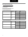
Service Procedures
Tire Pressure Control System 1
Key Features . . . . . . . . . . . . . . . . . . . . . . . . . . . . . . . . . 1
Component Description . . . . . . . . . . . . . . . . . . . . . . . . 2
Simplified System Schematic . . . . . . . . . . . . . . . . . . . . 4
Operator Instructions
Driver Display Module (DDM) . . . . . . . . . . . . . . . . . . . 5
Operator Control Panel (OCP) . . . . . . . . . . . . . . . . . . . 8
OCP Programming Chart . . . . . . . . . . . . . . . . . . . . . . 12
Diagnostics
Diagnostics . . . . . . . . . . . . . . . . . . . . . . . . . . . . . . . . 13
Troubleshooting Tips . . . . . . . . . . . . . . . . . . . . . . . . . 16
Service Code Summary . . . . . . . . . . . . . . . . . . . . . . . 17
Final System Checkout . . . . . . . . . . . . . . . . . . . . . . . .55
Pneumatic Control Unit - Cleaning and Inspection . . .57
Solenoid Assembly and Cartridge . . . . . . . . . . . . . . . .59
Service Guidelines . . . . . . . . . . . . . . . . . . . . . . . . . . . .61
Joint Compounds and Fittings . . . . . . . . . . . . . . . . . . .61
Air Filter Change . . . . . . . . . . . . . . . . . . . . . . . . . . . . .62
Troubleshooting Wheel End Seals . . . . . . . . . . . . . . . .63
Hose and Supply Tank Selection Chart . . . . . . . . . . . .65
Wire Harness
Connector Illustrations . . . . . . . . . . . . . . . . . . . . . . . .67
Electrical Schematic . . . . . . . . . . . . . . . . . . . . . . . . . . .68
Configuration Connections . . . . . . . . . . . . . . . . . . . . .70
Service Codes
Group: 1C! (Code 17) . . . . . . . . . . . . . . . . . . . . . . . . .
Group: 3C! (Codes 18, 76, 77) . . . . . . . . . . . . . . . . . .
Group: 4C! (Code 15) . . . . . . . . . . . . . . . . . . . . . . . . .
Group: 5C! (Codes 33, 34) . . . . . . . . . . . . . . . . . . . . .
Group: 12C! (Codes 51, 52, 53, 54, 55, 56) . . . . . . . .
Group: 1P! (Codes 11, 12, 13, 16, 22) . . . . . . . . . . . .
Group: 2P! (Code 14) . . . . . . . . . . . . . . . . . . . . . . . . .
Group: 3P! (Code 21) . . . . . . . . . . . . . . . . . . . . . . . . .
Group: 4P! (Codes 23, 24, 25) . . . . . . . . . . . . . . . . . .
Group: 5P! (Codes 26, 27, 28) . . . . . . . . . . . . . . . . . .
Group: 7P! (Codes 31, 32) . . . . . . . . . . . . . . . . . . . . .
Group: 8P! (Code 35) . . . . . . . . . . . . . . . . . . . . . . . . .
Group: 9P! (Codes 36, 37, 38) . . . . . . . . . . . . . . . . . .
Group: 10P! (Codes 41, 42, 43) . . . . . . . . . . . . . . . . .
Group: 11P! (Codes 44, 45, 46) . . . . . . . . . . . . . . . . .
Group: 12P! (Codes 61, 62, 63, 64, 65, 66) . . . . . . . .
Code: No Code . . . . . . . . . . . . . . . . . . . . . . . . . . . . . .
19
21
23
25
27
29
31
33
35
37
39
41
43
45
47
49
51
i
Table of Contents
General Information
General Information
Tire Pressure Control System
Spicer Tire Pressure Control System features driver control of
tire air pressure through:
•
Simple push button operation.
•
Independent Front, Rear, and Trailer operation.
•
Electronic braking priority for air system.
•
Vehicle speed sensing and response capability.
•
Self-diagnostics.
Key Features
Depressurized Control Lines
The only time the system is pressurized is when changing tire
pressures or during pressure checks. Wheel valves isolate the
tires from the rest of the system.
Electronic Braking Priority
A pressure switch, installed in the supply tank, controls the
TPCS’s use of air. This optimizes and protects the brake system’s primary tank pressures during system operation.
Self-Diagnostic and Auto Shut-Down
The Spicer TPCS provides self-diagnosis during operation. If
the system detects a problem, it will display a service code on
the driver interface to alert the driver. If necessary, it will close
the wheel valves and shut down.
1
Diagnostic Capability
The Spicer TPCS provides for easy troubleshooting using PCbased or industry standard tools. PC-supported diagnostics
improve troubleshooting, reduce maintenance time, provide
manual control of TPCS test sequences, and give historical
and active service code data.
Speed / Pressure Control and Warning
If truck speed exceeds the maximum allowable speed for a
given setting, a warning is activated by TPCS to alert the
driver. If speed is not reduced, the system automatically
inflates the tires to the appropriate pressure.
Manual Tire Inflation / Deflation
A valve stem has been included on each wheel valve and may
be used for manual inflation, deflation or measurement of tire
pressures.
Run Flat Operation
The TPCS normally checks tire pressures at intervals of 15
minutes. If possible tire damage is detected, the system will
activate Auto RUN FLAT. RUN FLAT reduces the pressure
check interval to 15 seconds, helping to assure that the tire
will remain inflated despite minor tire damage.
General Information
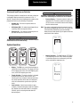
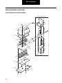
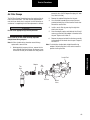
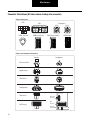
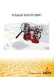
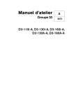
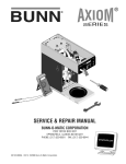
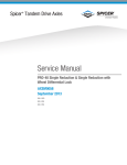
Component Description
Tire Pressure Control System Components
Driver Display Module (DDM)
OR
mph
kph
Tire
bar
Pres
psi
sure
Cont
rol
L /U
SELE
Component Description
Wheel
Valve
CT
HWY
OFF
HWY
EMER
RUN
FLA
T
Operator Control Panel (OCP)
Speed Sensor
(or Alternate Speed Inputs)
Pressure
Switch
Trailer
Connector
Pneumatic Control Unit
(shown with optional 3rd channel)
Electronic
Control Unit
2
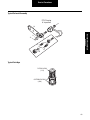
General Information
Wheel Valve
Vehicle Speed
All axles use a Wheel Valve (WV) at each end. Dual wheels are
typically connected through one WV to provide tire pressure
balance, although individual wheel valves for each tire may be
installed. When the system is idle, the wheel valve isolates the
tire(s), ensuring fail-safe operation. A standard valve stem is
included on the WV for manual inflation / deflation / pressure
checking.
Speed is read from the vehicle data link or a separate speed
sensor.
Electronic Control Unit (ECU)
The Electronic Control Unit (ECU) is the control center for the
entire Tire Pressure Control System. The ECU receives commands from the driver through the Driver Display Module
(DDM) or Operator Control Panel (OCP) and transmits and
monitors appropriate signals throughout the system.
Driver Interface
Options are available for the TPCS driver interface. The Driver
Display Module (DDM) includes two rocker switches and a
multi-function display. The Operator Control Panel (OCP) uses
a six-button keypad and graphic display.
Pneumatic Control Unit (PCU)
The Pneumatic Control Unit (PCU) is a solenoid controlled
manifold that controls the air system. It also contains the
Pressure Sensor (transducer) which reads tire pressures.
3
Pressure Switch
The Pressure Switch (PS) acts as an electronic brake priority
switch. It prevents the Tire Pressure Control System from
using air from the supply tank until the brake system is fully
charged. The PS also ensures that enough pressure exists for
the system to operate properly.
Air Lines
The Tire Pressure Control System uses a dedicated pneumatic
system plumbed from the vehicle’s existing supply tank.
Wiring
A wiring harness (Dana or OEM supplied) provides for electrical signals between appropriate components.
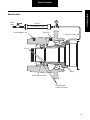
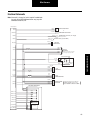
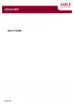
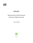
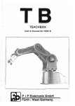
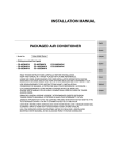
General Information
Simplified System Schematic
Tire
Tire
Wheel
Valve
Rotary
Joint
Compressor
Rotary
Joint
Wheel
Valve
User
Interface
Speed Sensor
Air Dryer
To Primary
and Secondary
Tanks
Pressure
Switch
Supply Tank
Electronic
Control Unit
Pneumatic
Control
Unit
PCU
Sensor
Simplified System
Schematic
Trailer
Connector
Seal
Assembly
Wheel
Valve
Seal
Assembly
Tire
Wheel
Valve
Tire
Seal
Assembly
Wheel
Valve
Tire
Seal
Assembly
Wheel
Valve
Tire
System Key
Pneumatic
Electrical
4
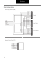
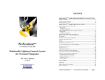
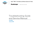
Operator Instructions
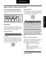
Operator Instructions - Driver Display Module (DDM)
TPCS may be equipped with one of two driver interface
devices: a Driver Display Module (DDM) or an Operator Control Panel (OCP). The Driver Display Module (DDM) is illustrated below and the following section explains the features
and use.
Check Tire Condition
This signal reports that one or more tires may be at a significantly lower pressure than the others and could indicate that a
tire is not holding pressure. Stop the vehicle immediately in a
safe place and identify the extent of tire damage.
Warning Icons
IMPORTANT
TPCS includes two distinct warnings to report possible tire
problems and inappropriate vehicle operation. You must take
immediate action to either reduce vehicle speed or check tire
condition whenever these warnings are displayed.
Reduce Vehicle Speed
CAUTION
Failure to respond may result in overheated tires and
possible tire failure.
This signal reports that the vehicle speed is too fast for the
pressure selected. You must either reduce speed or select a
higher pressure by pressing the appropriate key. Continued
operation in this mode will result in the system automatically
selecting a more appropriate pressure setting.
5
Tires can still go flat! Although the Tire Pressure Control
System is designed to identify under-inflated tires and fill
these tires to the desired operating pressure, you can still
expect that tires will occasionally be punctured or otherwise damaged during normal use and no longer retain air
reliably. A daily walk-around inspection of the vehicle at the
start of the day, including a manual check of the tires, is
still an important responsibility of the vehicle operator. Tire
damage is more apparent after the vehicle has been idle
overnight and will be more difficult to detect visually once
the TPCS equipped vehicle is in operation. Although observation of excessive inflation periods through the driver
interface can help identify a tire problem, you should have
damaged tires replaced prior to placing the vehicle in operation.
Operator Instructions
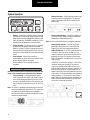
TPCS displays both the selected terrain and load, and may be
configured to display numerical tire pressures in PSI, if
desired. Tire pressures for the following terrain modes can be
programmed and may be selected by the operator:
•
Highway (Hy) - For travel on paved surfaces at
higher speeds.
•
Off Highway (OH) - For reduced speed operation on
secondary roads and unpaved surfaces.
•
Emergency (E) - For selection of extremely low tire
pressures to help free a stuck vehicle.
CAUTION
Operating a loaded vehicle at unloaded tire pressures may
result in tire overheating and reduced tire life or blowout.
•
Pressure Display - If the terrain switch is held in the
up position for >5 seconds, numerical tire pressures
(in PSI) for each channel will alternate in the display
with the selected mode.
Note: The system is designed to allow tire pressure increase
due to heat buildup during vehicle use. This system will
not automatically deflate these pressure buildups—
lower pressure mode selection by the operator must be
selected to initiate a deflate.
CAUTION
The Emergency selection is for extreme conditions only and
should not be used for normal driving.
System Operation
•
•
Display - The DDM uses a multi-function display to
indicate the current selections. The display will show
HY for highway pressures, OH for off-highway pressures, and E for emergency pressures.
•
Terrain Selection - The terrain selection is changed
by depressing the terrain rocker switch, up to
increase pressures and down to decrease pressures.
Any switch operation which does not change pressures will command the system to do a pressure
check.
•
Load Selection - Vehicle load selection is represented by a horizontal bar graph under the mode display. Depress the load rocker switch to change the
selection, up for increasing load and down for
decreasing load.
Channel Indicators - The DDM indicates FRT, RR or
TLR respectively for front, rear or trailer axle groups.
If a channel indicator is on continuously, that channel has achieved the target pressure.
6
Driver Display Module
Terrain and Load Pressure Selection
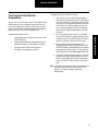
Operator Instructions
•
Service Code Indication - The DDM will not display
service codes directly but will exhibit two dashes if
service is required. (Accessing the service codes will
require a diagnostic tool).
Note: See the Service Codes Section to diagnose and repair.
•
RUN FLAT Indicator - If the TPC System determines
that a tire or tires may not be holding air, it may
reduce the pressure check interval to minimize the
possibility of air loss from the tire by switching to
RUN FLAT operation. (See RUN FLAT in the Key Features section).
If RUN FLAT is activated, the DDM will alternate the
display of the terrain setting and RF and the CHECK
TIRE indicator will be illuminated.
CHECKTIRE
7
Tire Pressure Control System
Programming
Spicer's Tire Pressure Control System is fully programmable,
allowing the technician to program tire pressures for each
channel (axle group) and maximum speeds for each terrain
mode. If equipped with the Driver Display Module (DDM),
programming must be done with a diagnostic tool.
Programmable settings include:
•
Individual pressure settings for the front, rear, and
trailer axle groups.
•
Loaded and unloaded axle group programming for
highway, off-highway, and emergency conditions.
•
Over speed warning threshold for highway,
off-highway and emergency conditions.
Operator Instructions
Operator Instructions - Operator Control Panel (OCP)
TPCS may be equipped with one of two driver interface
devices: a Driver Display Module (DDM) or an Operator Control Panel (OCP). The Operator Control Panel (OCP) is illustrated below and the following section explains the features
and use.
Check Tire Condition
This signal reports that one or more tires may be at a significantly lower pressure than the others and could indicate that a
tire is not holding pressure. Stop the vehicle immediately in a
safe place and identify the extent of tire damage.
bar
L /U
psi
HWY
SELECT
OFF HWY
EMER
RUN FLAT
Warning Icons
TPCS includes two distinct warnings to report possible tire
problems and inappropriate vehicle operation. You must take
immediate action to either reduce vehicle speed or check tire
condition whenever these warnings are displayed.
Reduce Vehicle Speed
CAUTION
Failure to respond may result in overheated tires and possible tire failure.
This signal reports that the vehicle speed is too fast for the
pressure selected. You must either reduce speed or select a
higher pressure by pressing the appropriate key. Continued
operation in this mode will result in the system automatically
selecting a more appropriate pressure setting.
mph
kph
IMPORTANT
Tires can still go flat! Although the Tire Pressure Control
System is designed to identify under-inflated tires and fill
these tires to the desired operating pressure, you can still
expect that tires will occasionally be punctured or otherwise damaged during normal use and no longer retain air
reliably. A daily walk-around inspection of the vehicle at the
start of the day, including a manual check of the tires, is
still an important responsibility of the vehicle operator. Tire
damage is more apparent after the vehicle has been idle
overnight and will be more difficult to detect visually once
the TPCS equipped vehicle is in operation. Although observation of excessive inflation periods through the driver
interface can help identify a tire problem, you should have
damaged tires replaced prior to placing the vehicle in operation.
Terrain and Load Pressure Selection
TPCS displays both the selected terrain and load, and may be
configured to display numerical tire pressures in PSI, if
desired. Tire pressures for the following terrain modes can be
programmed and may be selected by the operator:
•
HWY - For travel on paved surfaces at higher
speeds.
•
OFF HWY - For reduced speed operation on
secondary roads and unpaved surfaces.
•
EMER - For selection of extremely low tire pressures
to help free a stuck vehicle.
CAUTION
The EMER key is for extreme conditions only and should not
be used for normal driving.
8
Operator Control Panel
mph
kph
Operator Instructions
System Operation
•
mph
kph
bar
psi
Channel Indicators - The OCP display includes rings
inside the tires of the truck graphic. The pressure
shown in the display reflects the channel with the
lighted rings.
SELECT
Tire Pressure Control
mph
kph
L /U
•
•
•
HWY
OFF HWY
EMER
bar
RUN FLAT
Display - The OCP uses a graphic display to indicate
the selection for both terrain mode and vehicle load.
Above the selector keys labeled HWY (highway), OFF
HWY (off-highway), and EMER (emergency), an illuminated arrow designates the current selection.
Terrain Selection - The terrain selection is changed
by depressing the desired mode on the keypad.
When the system is actively changing tire pressure,
the arrow above the target mode will flash. Pressing
the key for a current mode will command a pressure
check.
•
•
Metric/English Indicator - The OCP may be programmed to display pressure in metric (BAR) or
English (PSI) units (see Programming section).
•
RUN FLAT Indicator - If the TPC System determines
that a tire or tires may not be holding air, it may
reduce the pressure check interval to minimize the
possibility of air loss from the tire by switching to
RUN FLAT operation. (See RUN FLAT in the Key Features section).
Load Selection - Vehicle load selection is
represented by an arrow above the rear wheels in the
graphic display. Depress the keypad
button labeled L/U to change from loaded to
unloaded.
If RUN FLAT is activated, an asterisk (*) will be illuminated in the display of the OCP. This asterisk
matches the symbol on the RUN FLAT key and it
indicates that the RUN FLAT feature is selected. The
OCP also allows the driver to select RUN FLAT, by
depressing that key, to manually reduce the pressure
check interval. This may be desirable when operating
under conditions (i.e. sharp rocks or construction
debris) where tire punctures may be anticipated. The
RUN FLAT feature will automatically de-select after
10 minutes, but may be re-selected.
Operating a loaded vehicle at unloaded tire pressures may
result in tire overheating and reduced tire life or blowout.
Pressure Display - If the keypad button labeled
Select is pressed after vehicle start, numerical pressures will be displayed sequentially for each active
channel. Subsequent actuation of the Select key will
lock the display on individual channels, or turn it off
again.
Note: The system is designed to allow tire pressure increase
due to heat buildup during vehicle use. This system will
not automatically deflate these pressure buildups—
lower pressure mode selection by the operator must be
selected to initiate a deflate.
mph
kph
bar
9
psi
Service Code Indication - The OCP will display service codes using a number and letter combination
followed by an exclamation point (!).
Note: See the Service Codes Section to diagnose and repair.
CAUTION
•
psi
mph
kph
bar
L/U
psi
HWY
SELECT
OFF HWY
EMER
RUN FLAT
Operator Instructions
Tire Pressure Control System
Programming
To program the system, follow these steps:
Enter the Tire Pressure Control System programming sequence by pressing the SELECT and L/U buttons at the same time. A flashing bar or PSI verifies
that you are in the programming mode and also indicates that the first selection, English or metric values, is ready for programming. Refer to "Operator
Control Panel Programming Sequence" for sample
procedure.
2.
Press the up/down arrows (on the L/U and EMER
keys) to select options or change settings (pressure
or speed) and press the SELECT button to record a
selection in memory and move to the next step.
3.
Press the SELECT button repeatedly to move
through the program steps, one step for each time
the SELECT button is pressed. Refer to the programming reference chart for specific Tire Pressure Control System pressure and speed programming steps.
4.
To complete the programming sequence, or exit the
programming mode, continue to press the SELECT
button to step through to the end of the procedure,
or press the SELECT and L/U buttons at the same
time.
Spicer's Tire Pressure Control System is fully programmable,
allowing the technician to program tire pressures for each
channel (axle group) and maximum speeds for each terrain
mode. The system allows programming directly through the
Operator Control Panel, or with a diagnostic tool.
Programmable settings include:
•
Individual pressure settings for the front, rear, and
trailer axle groups.
•
Loaded and unloaded axle group programming for
highway, off-highway, and emergency conditions.
•
Over speed warning threshold for highway,
off-highway and emergency conditions.
Note: If no buttons are pressed for more than one minute, the
Operator Control Panel will end the programming
sequence, saving any changes made during
programming.
10
Operator Control Panel
1.
Operator Instructions
Operator Control Panel Programming Sequence
Example for Step 1 Programming (see OCP Programming Chart)
Tire Pressure Control
+
SELECT
L /U
mph
kph
bar
Press at the same
time to enter
programming
down
arrow
psi
Flashing "bar" or "psi"
indicates you have
entered programming
up
arrow
Tire Pressure Control
or
L /U
EMER
SELECT
mph
kph
bar
Toggle
between metric
and English
Press to record a selection
in memory and move to
the next step
psi
Make selection
+
SELECT
L /U
Press at the same
time to exit
programming
down
arrow
Example for Step 7 Programming (see OCP Programming Chart)
+
+
SELECT
L /U
Enter programming
+
L /U
SELECT
Exit programming
11
SELECT
+
SELECT
+
SELECT
++
SELECT
+
SELECT
Press SELECT six times to go to step 7
up
arrow
or
SELECT
L/U
EMER
Press to set highway
unloaded drive pressure
Operator Instructions
OCP Programming Chart
Step Setting
Metric
SpeedTerrain Arrows
English
Indicator
Indicator
Loaded OCP Channel Indicator
Arrow
HWY OFF HWY EMER
Front
1
Metric / English
2
Highway Over Speed
3
Highway Loaded Front Pressure
On
On
4
Highway Loaded Rear Pressure
On
On
5*
Highway Loaded Trailer Pressure
On
On
6
Highway Unloaded Front Pressure
On
7
Highway Unloaded Rear Pressure
On
8*
Highway Unloaded Trailer
Pressure
On
9
Off-Highway Over Speed
10
Rear
Trailer
On
On
On
On
On
On
On
On
On
On
Off-Highway Loaded Front
Pressure
On
On
11
Off-Highway Loaded Rear
Pressure
On
On
12*
Off-Highway Loaded Trailer
Pressure
On
13
Off-Highway Unloaded Front
Pressure
On
14
Off-Highway Unloaded Rear
Pressure
On
15*
Off-Highway Unloaded Trailer
Pressure
On
16
Emergency Over Speed
17
Emergency Loaded Front Pressure
On
On
18
Emergency Loaded Rear Pressure
On
On
19*
Emergency Loaded Trailer
Pressure
On
On
20
Emergency Unloaded Front
Pressure
On
21
Emergency Unloaded Rear
Pressure
On
22*
Emergency Unloaded Trailer
Pressure
On
On
On
OCP Programming Chart
On
On
On
On
On
On
On
On
On
On
On
On
On
On
* 3 Channel Only
12
Diagnostics
Diagnostics
This section covers the equipment and procedures used to
find and correct Tire Pressure Control System problems.
Service Codes
Test Equipment
The Service Codes are described in the Troubleshooting
section. Some service codes also identify the component that
is associated with the problem. A list of possible causes is
shown in order of most likely occurrence.
Tire Pressure Control System troubleshooting can be
performed at three levels:
1.
PC diagnostics.
2.
Handheld tester.
3.
Operator Control Panel service codes (if vehicle is
equipped with an OCP).
Regardless of the testing equipment used, the troubleshooting procedures will be based upon the diagnostic service
codes. Diagnostic tools offer the advantages of computeraided testing without interpreting service codes.
Tire Pressure Control System Diagnostics
The onboard system diagnostics are an important feature of
Spicer’s Tire Pressure Control System. This section describes
the use of service codes to identify Tire Pressure Control
System operating problems.
The Tire Pressure Control System uses a code to identify service issues. The codes can be extracted from the ECU memory using a diagnostic service tool equipped with the
appropriate software. In addition, systems equipped with an
Operator Control Panel (OCP) will report codes directly on the
display. Refer to the service code chart for more detailed
information on service codes.
Historical Service Codes
Any time a fault occurs the system will log a fault in memory
of the ECU. If the system becomes inoperative, the Driver Display Module (DDM) will report two dashes (- -) or an actual
service code will be displayed on the Operator Control Panel.
(Only the most recent code is displayed by the
Operator Control Panel). Historical codes are stored in
memory. Historical codes can only be accessed by a
diagnostic tool. Historical codes are automatically cleared
after 50 ECU resets with no active faults.
13
Test Modes
Diagnostic tools allow the system to be placed in several
diagnostic modes:
Info - Display ECU information and configuration.
Codes - Active and historic codes are listed as reported by the
ECU.
Monitor (Normal) - TPCS operates normally, while status of
system components is observed.
Test - The following operations can be performed on each
channel (axle group):
•
Check & Hold - System checks and
displays the pressures, then holds pressure in air
lines (quick test of control line and seal integrity).
•
Deflate - System "manually" deflates (test the
deflation signal).
•
Inflate - System "manually" inflates (test for large
leaks).
•
Hold - Pressure is held in control lines (test for small
leaks).
Setup - Allows the technician to modify parameters such as
target tire pressures, etc.
Diagnostics
PC Diagnostics
CAUTION
A battery charger is not an adequate source of power.
Visit www.dana.com for free download of Dana Diagnostic
Tool (DDT).
PC diagnostics are easy to use and provide the quickest
diagnostic capabilities.
•
Retrieve historical data, faults and tire pressures.
•
Pressurize system to detect leaks.
•
Access troubleshooting flowcharts and service
procedures.
For these types of interface boxes to work with the Dana
Diagnostic Tool program, you must install a "RP1210 driver"
program provided by the manufacturer of the interface box.
If you do not have this program, it can normally be obtained
from the manufacturer's web site. Please contact the
manufacturer of your interface box if you have any questions
regarding this process.
Connect to diagnostic
connector.
Attach computer to RP1210A
communications box.
Download free Dana Diagnostic
Tool from dana.com.
Note: Program requires
Windows 98 or newer.
Follow on-screen
instructions.
14
Diagnostics
To use this program, an RP1210A compatible interface box
and cables are needed to connect the PC to the vehicle.
Diagnostics
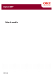
Handheld Tester
Multimeter
A Prolink handheld tester may be used to read and clear
service codes and to obtain a short description of failures. The
tester can initiate test sequences for controller outputs and
can also read system parameters when equipped with the
Dana program card.
Based upon system schematics and aided by component
specific service codes, a multimeter can be used to check
sensor and solenoid resistances and to find wiring harness
faults. The multimeter can be used to check the Tire Pressure
Control System wiring and components for:
MICRO PROCESSOR SYSTEMS INC.
KENT-MOORE
Pro-Link
15
7
8
9
4
5
6
1
2
3
0
ENTER
FUNC
•
Continuity
•
Ground
•
Broken wires
•
Open circuits
•
Shorted circuits
•
Incorrect battery voltage
Diagnostics
Troubleshooting Tips
This checklist outlines some general hints and guidelines that
will be helpful in tracking down and correcting operating
problems.
Operator Control Panel only displays one active code.
Only the most recent service code displays on the Operator
Control Panel. In troubleshooting, be alert for related codes.
Use of a diagnostic tool offers the advantages of spotting multiple active codes as well as retrieving historical codes.
Disconnect the Electronic Control Unit connector with ignition off.
To avoid setting electrical service codes, make sure that the
ignition is off before unplugging the wire harness connection
at the Electronic Control Unit module.
Reconnect the connector before switching on the ignition.
System is not continually pressurized.
When troubleshooting P! service code faults, keep in mind
that the air system is only pressurized as needed (for example, in the inflate mode). This means that such procedures as
checking for leaks require the system to be in an active,
pressurized state. This can be accomplished most easily by
using a diagnostic tool.
Basic vehicle air and power systems are not covered in this
guide.
The Tire Pressure Control System requires air pressure and
electrical power supply from the base vehicle systems.
Diagnosis and service of these systems is outside the scope
of this manual.
Some faults will halt inflate or deflate sequences.
Upon sensing some service codes, the Tire Pressure Control
System will immediately go to the "maintain" mode. This may
cause mode arrows to stop flashing before the system has
actually attained the pressures for the indicated mode.
16
Troubleshooting Tips
A cleared code alone does not indicate a corrected
problem.
A code is set by a specific fault condition and may be cleared
by switching the ignition off. It's possible to clear a code (i.e.,
remove it from the driver interface) only to have it display
again when the fault condition reoccurs. To ensure that a
problem is fixed, you must run the system through the same
operating modes that caused the problem and verify that the
service code does not appear.
C! Service Codes are often connection problems.
The most likely cause of component faults will be damaged
wires or connections. As a first step in troubleshooting all C!
service codes, switch off vehicle ignition, then disconnect
applicable connectors and inspect for damage. (Switching off
the ignition is required before disconnecting the harness at
the Electronic Control Unit, but is also a recommended practice before all other electrical system disconnections.) Clean
or repair all suspicious connections before proceeding.
Diagnostics
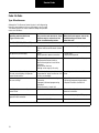
Service Code Summary
Group Code
System Status
Description
1C!
17
No Operation
Power - battery voltage out of range at the ECU
3C!
18
Normal Operation
Speed Signal - no speed detected during multiple ignition cycles
76
Normal Operation
J1587 Speed Message - not receiving expected messages on J1708 data link
77
Normal Operation
J1939 Speed Message - not receiving expected messages on data link
4C!
15
Inflate Only
Display Control Communications - ECU not receiving communications from user
interface
5C!
33
No Operation
PCU Sensor - signal voltage too high
34
No Operation
PCU Sensor - connector unplugged; signal voltage too low
51
No Operation
PCU Solenoid, Front - connector unplugged; faulty wiring or solenoid
52
No Operation
PCU Solenoid, Rear - connector unplugged; faulty wiring or solenoid
53
No Operation
PCU Solenoid, Trailer - connector unplugged; faulty wiring or solenoid
54
No Operation
PCU Supply Solenoid - connector unplugged; faulty wiring or solenoid
55
No Operation
PCU Deflate Solenoid - connector unplugged; faulty wiring or solenoid
56
No Operation
PCU Control Solenoid - connector unplugged; faulty wiring or solenoid
11
No Deflation
Deflate Signal, Front - could not generate a vacuum in control lines
12
No Deflation
Deflate Signal, Rear - could not generate a vacuum in control lines
13
No Deflation
Deflate Signal, Trailer - could not generate a vacuum in control lines
16
Normal Operation
Deflate Signal - could not generate a vacuum in one or more channel's control lines
22
Inflate Only
Deflate Signal, PCU - could not generate a vacuum in pneumatic control unit
2P!
14
Inflate Only
Deflate Trend - tire pressure did not decrease properly during deflate
3P!
21
Inflate Only
Vacuum - unintentional vacuum in PCU
4P!
23
Pressure Check Only Between Modes, Front - inflated or deflated too slowly
24
Pressure Check Only Between Modes, Rear - inflated or deflated too slowly
25
Pressure Check Only Between Modes, Trailer - inflated or deflated too slowly
26
Pressure Check Only Low Pressure, Front - open line or large seal leak
27
Pressure Check Only Low Pressure, Rear - open line or large seal leak
28
Pressure Check Only Low Pressure, Trailer - open line or large seal leak
31
Pressure Check Only Pressure Switch - failed closed or wiring shorted
32
Pressure Check Only Low Air Supply - pressure switch did not close
8P!
35
Pressure Check Only Atmospheric - PCU sensor reading out of range
9P!
36
Channel Inoperative
Inflate Trend, Front - tire pressure decreased during an inflate
37
Channel Inoperative
Inflate Trend, Rear - tire pressure decreased during an inflate
38
Channel Inoperative
Inflate Trend, Trailer - tire pressure decreased during an inflate
12C!
1P!
5P!
7P!
17
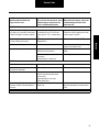
Diagnostics
Group Code
System Status
Description
10P!
41
Inflate Only
Tire Leak, Front - not passing tire pressure confirm check (multiple attempts)
42
Inflate Only
Tire Leak, Rear - not passing tire pressure confirm check (multiple attempts)
43
Inflate Only
Tire Leak, Trailer - not passing tire pressure confirm check (multiple attempts)
44
Pressure Check Only Tire Leak, Front - tire pressure imbalance or line leak
45
Pressure Check Only Tire Leak, Rear - tire pressure imbalance or line leak
46
Pressure Check Only Tire Leak, Trailer - tire pressure imbalance or line leak
61
Normal Operation
Sluggish Shut Off, Front - lost minor pressure during wheel valve shut off
62
Normal Operation
Sluggish Shut Off, Rear - lost minor pressure during wheel valve shut off
63
Normal Operation
Sluggish Shut Off, Trailer - lost minor pressure during wheel valve shut off
64
Normal Operation
Shut Off Failure, Front - cannot close wheel valve(s) and vent lines
65
Normal Operation
Shut Off Failure, Rear - cannot close wheel valve(s) and vent lines
66
Normal Operation
Shut Off Failure, Trailer - cannot close wheel valve(s) and vent lines
11P!
12P!
-
Reserved (47, 48)
57
Spare #1 - connector unplugged; faulty wiring or component
58
Spare #2 - connector unplugged; faulty wiring or component
67-68
Reserved (67, 68)
71-75
Reserved (71-75)
78
Reserved (78)
Service Code Summary
47-48
18
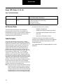
Service Codes
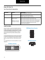
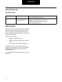
Group: 1C! (Code 17)
Type: Power
System Mode
Condition
Possible Causes
(Listed in Likely Order of Occurrence)
No Operation
Power out of range
- Low battery voltage.
- Poor ground connection to Electronic Control Unit.
- Poor switched ignition connection to Electronic Control Unit.
- High vehicle electrical system voltage.
- Faulty Electronic Control Unit.
Code Description
Group 1C! (17) indicates a power fault and sets when the system power is outside the acceptable range of 9 to 32 volts.
The fault could be caused by low battery power or some other
problem with the basic vehicle electrical system.
If the vehicle power system checks out satisfactorily, other
possible causes include bad Electronic Control Unit (ECU)
connections, or a faulty Electronic Control Unit.
In inspecting circuits and connections for a Code 1C! fault,
pay particular attention to a bad ground connection that could
be causing the fault.
See "Troubleshooting Tips" for general guidelines on system
diagnostics.
ECU Harness Connector
A B C D E
A B C D E
A B C D E
19
F G H J K
F G H J K
F G H J K
3
2
1
Service Codes
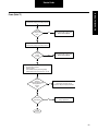
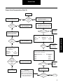
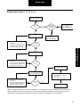
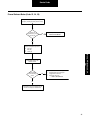
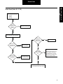
Group: 1C! (Code 17)
Power (Code 17)
With ignition switched on and engine running,
measure battery voltage across battery terminals.
Is voltage
reading > 32
volts?
Yes
Base vehicle power is out of range.
Refer to Service Manual
No
With ignition switched on but engine not running,
measure battery voltage across battery terminals.
Is voltage
reading
< 9 volts?
Yes
Base vehicle power is out of range.
Refer to Service Manual
No
Switch off ignition.
Disconnect ECU connector.
Switch on ignition.
Check SWACC circuit by measuring voltage
between ECU harness connector pins K1 and K2.
Does
measured
voltage match battery voltage
reading obtained in
previous
step?
No
Inspect for failure in SWACC circuit including
vehicle power panel and/or ground
connections. Repair or replace as indicated.
Yes
Is code 1C!
fault cleared?
No
Inspect wire sockets and ECU pins.
If okay, replace ECU.
Yes
Complete
20
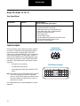
Service Codes
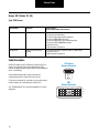
Group: 3C! (Codes 18, 76, 77)
Type: Speed Signal
System Mode
Condition
Possible Causes
(Listed in Likely Order of Occurrence)
Normal Operation
No speed signal
- ECU power cycled 50 times without vehicle being moved.
- Sensor disconnected or loose plug.
- Either speed sensor wire is open (broken wire).
- Either speed sensor wire is shorted to ground
(bare wire is touching the frame).
- Faulty speed sensor.
- Sensor actuation failure.
- Tang drive broken/disconnected on mechanical sensor.
- Gap not adjusted correctly on pole sensor.
- Sensor wires shorted together.
Code Description
Group 3C! indicates a faulty speed sensor signal. In general,
the system is configured to accept speed signals from any
one of several sources (analog or digital; J1708/J1587,
J1939). In this standard configuration, a loss of speed signal
fault is indicated by code 18. In some specific instances, a
vehicle may be configured to only accept speed from a specific data link. In these cases, codes 76 (SAE J1708/J1587)
and code 77 (SAE J1939) may be used to indicate a speed
signal fault.
•
A wiring or sensor connection.
•
A misadjusted or faulty sensor.
•
A missing data link speed signal. (J1939 or J1708/
J1587)
Note: These codes will occur if ECU power has been cycled 50
times and no speed signal is received. Fifty power
cycles can occur after 25 engine starts without moving
the vehicle, however the code will clear as soon as a
speed signal is received.
See "Troubleshooting Tips" for general guidelines on system
diagnostics.
21
Speed Sensor
Harness Connector
A
B
ECU Harness Connector
A B C D E
F G H J K
A B C D E
F G H J K
F G H J K
A B C D E
3
2
1
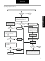
Service Codes
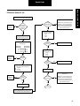
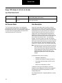
Speed Signal (Codes 18, 76, 77)
This fault is set when ECU power has been cycled 50 times without sensing any speed input. Move vehicle at greater than 5 mph.
Did fault clear?
Yes
Complete
No
Group: 3C! (Codes 18, 76,
77)
Determine type of speed sensor input:
Digital (TTL signal from engine ECU or speedometer)
Analog (pole sensor or VR type)
Data Link (SAE J1708/1587 or SAE J1939)
Check adjustment on threaded
pencil speed sensor or drive tang on
mechanical speed sensor.
Analog
Sensor type?
Data Link
Use industry standard tools to verify
data link signal is OK.
Digital
Sensor problem?
Yes
Repair as necessary.
No
Switch off ignition.
Disconnect speed sensor and ECU from harness.
Check for shorts on ECU connector:
- F2 to F3
- F2 to K2
- F3 to K2
Was a short found?
Yes
Switch off ignition.
Disconnect speed input from signal
source and ECU from harness.
Check for shorts on ECU connector
F1 to K2.
Check continuity of ECU
connector F1 to speed input.
Repair harness
as necessary.
Repair and verify speed signal source.
No
Move vehicle at
greater than 5 mph.
Check for opens:
Short speed sensor harness connector A
and B together.
Measure continuity between F2 and F3 on
ECU connector.
Was circuit open?
No
Replace speed sensor.
Yes
Did active
code clear?
Repair harness
as necessary.
Yes
Complete
No
Replace ECU.
Note: ECUs are not a typical cause of problems. If an ECU
is replace, the system should be carefully rechecked to
make sure the problem has been fixed and does not reoccur.
22
Service Codes
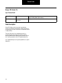
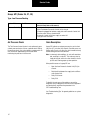
Group: 4C! (Code 15)
Type: Display Control Communications
System Mode
Condition
Possible Causes
(Listed in Likely Order of Occurrence)
Inflate Only
Blank Display
- No power to Driver Interface.
- No ground connection to Driver Interface.
- System voltage out of range (9-19 volts DC).
Inflate Only
Operator Control Panel
displays logo only
- No power or ground to ECU.
- Driver Interface to Electronic Control Unit lines open.
- Driver Interface to Electronic Control Unit lines shorted to ground.
- Driver Interface to Electronic Control Unit lines shorted to power.
- Driver Interface to Electronic Control Unit lines shorted together.
- Faulty Driver Display Module/Operator Control Panel.
- Faulty Electronic Control Unit.
DDM displays dash dash
(nothing else on display)
Code Description
Group 4C! indicates a communication problem between the
Electronic Control Unit (ECU) and the driver interface (either
the Driver Display Module or Operator Control Panel). Code
4C! will only be observable on a diagnostic tool as code 15. It
will not show on the Operator Control Panel. Instead, the
Operator Control Panel may be blank (indicating a power
problem).
All of the troubleshooting steps for code 4C! involve checking
the condition of Electronic Control Unit and driver interface
circuits. If no circuit problems are found, Code 4C! indicates
either a faulty driver interface or a faulty Electronic Control
Unit.
See "Troubleshooting Tips" for general guidelines on system
diagnostics.
A B C D E
23
F G H J K
F G H J K
F G H J K
5
6
4
7
3
8
2
9
1
10
OCP Harness Connector
5 6
ECU Harness Connector
A B C D E
A B C D E
DDM Display Harness Connector
3
2
1
8 9 10
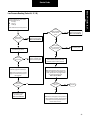
Service Codes
Display Control Communications (Code 15)
Turn on ignition.
With vehicle running, measure battery
voltage across battery terminals.
Is voltage
reading > 19
volts?
Yes
Yes
Is
driver interface
completely
blank?
Base vehicle power is out of range.
Refer to Service Manual
No
Switch ignition off.
Disconnect ECU connector.
Disconnect driver interface connector.
Switch ignition on.
Verify adequate voltage (9-32 Vdc) between
power (ECU harness connector pin K1) and
ground (ECU harness connector pin K2).
No
With ignition switched on but engine
not running, measure battery
voltage across battery terminals.
Inspect fuses/
repair harness
to power ECU.
No
Is voltage within range?
Yes
Check continuity between:
Yes
Base vehicle power is out of range.
Refer to Service Manual
No
DDM Display
Harness Pin
6
7
Is there
continuity?
Disconnect driver interface.
With ignition on, measure
voltage between:
DDM Display
Harness Pins
4 and 5
or
or
Inspect and repair
faulty
communications
circuit in harness.
No
Yes
Check for communication circuits shorted to ground, power or
shorted to each other. Check between:
OCP
Harness Pins
5 and 6
Does
measured
voltage match
battery voltage reading
obtained
in previous
step?
OCP
Harness Pin
9
10
Group: 4C! (Code 15)
Is voltage
reading < 9
volts?
ECU
and
Harness Pin
K3
J3
DDM Display Harness Pins
6 and 4
7 and 4
7 and 5
6 and 5
6 and 7
No
or
OCP Harness Pins
9 and 6
10 and 6
9 and 5
10 and 5
9 and 10
Repair harness power or ground
connections to driver interface.
Is any circuit shorted?
Yes
Inspect and
repair faulty
wire or
connection.
Yes
Complete
No
Yes
Replace driver interface.
Replace driver interface.
Switch on ignition.
Replace ECU.
Note: ECUs are not a typical cause of
problems. If an ECU is replaced, the
system should be carefully rechecked
to make sure the problem has been
fixed and does not reoccur.
No
Is driver
interface functioning
correctly?
24
Service Codes
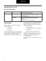
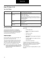
Group: 5C! (Codes 33, 34)
Type: PCU Sensor
System Mode
Condition
Possible Causes
(Listed in Likely Order of Occurrence)
No operation
No PCU sensor reading
- PCU Sensor electrically disconnected.
- PCU Sensor signal wire open.
- PCU Sensor signal wire shorted to ground.
- PCU Sensor XDCR VREF wire open.
- PCU Sensor XDCR VREF wire shorted to ground.
- PCU Sensor XDCR COMMON wire open.
- Faulty PCU Sensor.
- Faulty Electronic Control Unit.
No operation
High pressure transducer
reading
- PCU Sensor signal wire shorted to VBATT or XDCR VREF.
- Faulty PCU Sensor.
- Faulty Electronic Control Unit.
Code Description
Group 5C! displays when the Electronic Control Unit (ECU)
receives an unusually high or low reading from the PCU
Sensor. A diagnostic tool will specify 33 for a high reading and
34 for a low reading.
PCU Sensor
Harness Connector
A
B
C
Initial troubleshooting steps involve checking for a
shorted-to-ground or an open PCU Sensor circuit.
If the circuits check out OK, secondary causes could involve a
faulty transducer or a faulty Electronic Control Unit.
See "Troubleshooting Tips" for general guidelines on system
diagnostics.
ECU
Harness Connector
A B C D E
A B C D E
A B C D E
25
F G H J K
F G H J K
F G H J K
3
2
1
Service Codes
With ignition off, inspect socket connections at
ECU connector and at PCU sensor 3-way.
Replace ECU.
Repair
conditions as
necessary.
Are
connections
mechanically and
electrically
sound?
No
Disconnect the ECU connector
and the PCU sensor connector.
Check continuity between the
following points:
Is there
continuity?
PCU Sensor
Harness Pin
C
B
A
No
ECU Harness
Connector Pin
H1
H2
H3
No
Note: ECUs are not a typical cause of
problems. If an ECU is replaced, the
system should be carefully rechecked
to make sure the problem has been
fixed and does not reoccur.
Yes
Check harness inside PCU
cover for continuity:
A to A
B to B
C to C
Yes
Inspect and
repair faulty
harness.
Is voltage
between 4.9 and
5.1V?
No
Repair mini-harness inside cover.
Yes
Repair mini-harness inside cover.
Yes
Check harness inside
PCU cover for shorts:
A to B
B to C
C to A
Is there
continuity?
Yes
Check for short circuits between each
pair of PCU sensor harness pins:
A and B
B and C
C and A
Are any
shorted?
No
Replace PCU sensor.
Replace ECU.
Inspect and
repair faulty
harness.
No
Are any
shorted?
Is the active
fault cleared?
Yes
No
Note: ECUs are not a typical cause of
problems. If an ECU is replaced, the
system should be carefully rechecked
to make sure the problem has been
fixed and does not reoccur.
Yes
Reconnect ECU connector.
Complete
Check voltage between PCU sensor harness
pin B and ground with ignition switch on.
26
Group: 5C! (Codes 33, 34)
PCU Sensor (Codes 33, 34)
Service Codes
Group: 12C! (Codes 51, 52, 53, 54, 55, 56)
Type: PCU Solenoids
•
Front (51)
•
Rear (52)
•
Trailer (53)
•
Supply (54)
•
Deflate (55)
•
Control (56)
System Mode
Condition
Possible Causes
(Listed in Likely Order of Occurrence)
No operation
Pneumatic Control Unit
solenoid failed electrical
diagnostic test
- Connector unplugged or faulty wiring.
- Solenoid wire open.
- Solenoid wire shorted to ground.
- Solenoid wire shorted to power.
- Faulty solenoid.
- Faulty Electronic Control Unit.
Code Description
Group 12C! indicates an electrical fault in the Pneumatic
Control Unit (PCU). Codes 51 through 56 specifically
designate which solenoid in the PCU is faulty. System
operation is disabled when this fault is detected.
PCU Connector
E
D
C
F
G
H
B
A
K
The system shuts down in a fail-safe mode and turns off
power to the solenoids.
The troubleshooting tree first tests internal solenoid circuitry.
Resistance outside the specified range of 7 to 25 ohms
indicates a defective solenoid. Successive steps check
continuity of the wire harness circuits between the Pneumatic
Control Unit and the Electronic Control Unit (ECU). If the
problem can be traced to a faulty circuit or connector, make
the necessary repairs. If the troubleshooting routine leads to a
problem with the solenoid itself, the Pneumatic Control Unit
must be repaired or replaced. If both the solenoid and the
circuitry check out, the Electronic Control Unit is faulty.
See "Troubleshooting Tips" for general guidelines on system
diagnostics.
PCU Harness
Connector
A
K
C
D
E
H
G
F
ECU
Harness Connector
A B C D E
A B C D E
A B C D E
27
B
F G H J K
F G H J K
F G H J K
3
2
1
Service Codes
PCU Solenoids (Codes 51, 52, 53, 54, 55, 56)
Code 12C! Indicates one or more solenoid faults. Use service tool to determine the
specific solenoid. When the troubleshooting instructions refer to connector test
points, use chart select the pin test point for use with the particular fault code you
are diagnosing.
Any
Code
Any
Code
Front
(51)
Rear
(52)
Trailer
(53)
H
F
G
E
K
K2
K2
D1
D2
E1
Supply
(54)
Deflate
(55)
Control
(56)
A
C
B
D
K2
B1
B2
B3
A
Are any pins
shorted to
ground?
Yes
Repair or replace
connections,
coils or PCU.
No
Disconnect ECU harness
connectors.
Check continuity of harness pins
shown in chart for given fault
code: PCU harness connector to
ECU harness connector.
Switch off ignition.
Disconnect harness at
PCU 10-way connector.
Measure solenoid coil resistance on PCU 10-way connector.
Front (51): F – G
Rear (52): F – E
Trailer (53): A – K
Supply (54): H – C
Deflate (55): H – B
Control (56): F – D
Are circuits
continuous?
No
Yes
Yes
Measure at PCU harness connector.
Verify continuity between:
- A and F
- A and H.
Verify no continuity between any combination
of pins B, C, D, E, G, K on PCU harness
connector and K2 on ECU harness connector.
(Do not use multi-meter’s continuity “beep
mode,” as most meters will falsely identify the
7-25 ohm coils as shorted.)
Check for shorts between PCU connector
pins B, C, D, G, E, K and vehicle ground.
(Do not use multi-meter’s continuity “beep
mode,” as most meters will falsely identify
the 7-25 ohm coils as shorted.)
Are
connections
OK?
Are all
resistance
measurements
7-25 ohms?
No
Repair or replace
harness.
Repair or replace
connections, coils or PCU.
No
Repair or replace
harness.
Yes
A
Replace ECU.
Note: ECUs are not a typical cause of problems. If an
ECU is replaced, the system should be carefully
rechecked to make sure the problem has been fixed
and does not reoccur.
28
Group: 12C! (Codes 51,
52, 53, 54, 55, 56)
Solenoid/
Code
PCU Harness
Connector
ECU Harness
Connector
Service Codes
Group: 1P! (Codes 11, 12, 13, 16, 22)
Type: No Deflate Signal
System Mode
Condition
Possible Causes
(Listed in Likely Order of Occurrence)
Inflate Only
Inadequate vacuum in the
Pneumatic Control Unit
- Plugged or restricted Pneumatic Control Unit vent line.
- Faulty Pneumatic Control Unit.
Inflate Only
No sustained vacuum in
control lines
- Line leaks.
- Air seals, oil lip seals.
Code Description
Group 1P! indicates inadequate vacuum in the Pneumatic
Control Unit (PCU) prior to channel selection, or failure to
sustain a vacuum in the control lines following channel
selection. These codes will be set when the nominal vacuum
of 26" Hg drops to 17" Hg. Codes can be generated by one
channel, multiple channels or a combination of channels.
When a deflate is requested, the system first shuts off all the
channel control lines and generates a vacuum in the Pneumatic Control Unit alone. A failure to generate this vacuum
will result in Diagnostic Code 22.
Once the vacuum has been established in the Pneumatic
Control Unit, the individual channel control line(s) are opened
and a vacuum is routed to them. If a vacuum is not sustained
in the control lines, a 1P! fault is logged as follows:
11 - Front Channel
12 - Rear Channel
13 - Trailer Channel
16 - Individual channels OK but a combination of
channels results in low vacuum.
Note: If a vacuum loss occurs during an attempt to deflate
two or more channels at the same time, the system will
halt the deflate and re-attempt it one channel at a time.
This will result in a Code 16 being stored in the ECU.
29
Group1P! can be caused by:
•
Line leak.
•
Air seal or oil lip seal leaks.
•
Plugged or restricted Pneumatic Control Unit vent
line.
•
Faulty Pneumatic Control Unit.
To identify the root cause of the problem, connect the
diagnostic tool (see Diagnostic Section for test equipment
and descriptions) and follow the procedure in the 1P!
Troubleshooting Tree.
See "Troubleshooting Tips" for general guidelines on system
diagnostics.
Service Codes
No Deflate Signal (Codes 11, 12, 13, 16, 22)
Using the diagnostic tool, test
vacuum in isolated PCU.
Is the vacuum
< 6" Hg?
No
Yes
No
Replace PCU and recheck
system.
Refer to Service Manual
Yes
Initiate deflate mode on the steer
channel. Record the reading.
Initiate pressure check and hold on
steer channel.
Check all air lines and fittings for leaks
as well as exhaust port of wheel valves.
Make repairs to faulty components.
Is the PCU
vent line plugged or
restricted?
Repair PCU restriction and
recheck system.
Refer to Service Manual
Is the vacuum
> 20" Hg?
No
Group: 1P! (Codes 11, 12,
13, 16, 22)
Yes
Initiate deflate mode on the drive
channel. Record the reading.
Initiate pressure check and hold on
drive channel.
Check all air lines and fittings for leaks
as well as exhaust port of wheel valves.
Make repairs to faulty components.
Is the vacuum
> 20" Hg?
No
Problem is a cumulative effect
of individual channel leaks.
Yes
Initiate deflate mode on the trailer
channel. Record the reading.
Initiate pressure check and hold on
trailer channel.
Check all air lines and fittings for leaks
as well as exhaust port of wheel valves.
Make repairs to faulty components.
No
Is the vacuum
> 20" Hg?
Initiate inflate pressure hold on channel
with the lowest vacuum reading.
Check for leaks.
Make repairs to faulty components.
Yes
Verify by initiating deflate
mode on repaired channels.
Note: Line leakages occasionally occur which are unidirectional; i.e., they might occur under vacuum and not pressure (or vice-versa).
Inability to determine the cause of vacuum loss on an individual channel may dictate replacement of air lines and/or fittings on that
channel. Be sure all replaced air lines and fittings are identical in all respects, including length, to the parts replaced.
30
Service Codes
Group: 2P! (Code 14)
Type: Deflate Trend
System Mode
Condition
Possible Causes
(Listed in Likely Order of Occurrence)
Inflate Only
Pressure increased or failed - Plugged or restricted control lines.
to drop appropriately
- Plugged or restricted Pneumatic Unit vent line.
- Plugged or restricted wheel valve exhaust port.
- Faulty Pneumatic Control Unit.
Code Description
Group 2P! is the result of a deflate that did not occur properly.
The system measures tire pressure before and after each
deflate. If the pressure readings indicate that the pressure
either increased or failed to drop properly, the system shuts
down the deflate sequence.
Group 2P! can be caused by:
•
Plugged or restricted control lines.
•
Plugged or restricted Pneumatic Control Unit vent
line.
•
Contaminated or faulty Pneumatic Control Unit.
To identify the root cause of the problem, connect the
diagnostic tool (see Diagnostics Section for test equipment
and descriptions) and follow the procedure in the 2P!
Troubleshooting Tree.
See "Troubleshooting Tips" for general guidelines on system
diagnostics.
31
Service Codes
Group: 2P! (Code 14)
Deflate Trend (Code 14)
Use diagnostic tool to manually
deflate the tires on each channel.
All tires on each
channel deflate?
No
Check for conditions preventing vacuum reaching tires:
Restrictions in valve stems (valve cores, filters, rubber, etc.)
Restricted PCU vent line
Loss of vacuum on channel (see 1P! flowchart)
Inoperative or restricted wheel valve
Yes
Replace or clean PCU.
Caution: Verify clean (no oil), dry air system on vehicle. This
condition can be caused by contamination in PCU. Reference
PCU Cleaning and Inspection for cleaning procedure.
Verify repair by monitoring
system deflate.
32
Service Codes
Group: 3P! (Code 21)
Type: Vacuum Fault
System Mode
Condition
Possible Causes
(Listed in Likely Order of Occurrence)
Inflate Only
Inappropriate vacuum
generation
- Faulty or contaminated Pneumatic Control Unit.
Code Description
Group 3P! displays when the system is generating a
vacuum at a time when the Electronic Control Unit (ECU) is
not requesting a vacuum. Creation of an unexpected vacuum
is highly unlikely.
The most likely cause of an unexpected vacuum is a
contaminated or faulty Pneumatic Control Unit (PCU).
Verify the problem before replacing the Pneumatic Control
Unit. See the procedure in the 3P! Troubleshooting Tree.
See "Troubleshooting Tips" for general guidelines on system
diagnostics.
33
Service Codes
Vacuum Fault (Code 21)
Verify the problem.
Replace or clean PCU.
Group: 3P! (Code 21)
Caution: Verify clean (no oil), dry air system on vehicle. This
condition can be caused by contamination in PCU. Reference
PCU Cleaning and Inspection for cleaning procedure.
Verify the repair.
34
Service Codes
Group: 4P! (Codes 23, 24, 25)
Type: Channel Between Modes
System Mode
Condition
Possible Causes
(Listed in Likely Order of Occurrence)
Pressure Check Only
Slow Inflate
- Faulty compressor.
- Restricted flow at wheel valve air filters or tire valve stems.
- Crimped or plugged lines.
Slow Deflate
- Restricted flow at wheel valve air filters or tire valve stems.
- Plugged or restricted Pneumatic Control Unit vent port.
- Leaking lines.
- Plugged or restricted wheel valve exhaust port.
Code Description
Group 4P! displays if any channel inflates or deflates too
slowly as shown below:
•
23 - Front Channel
•
24 - Rear Channel
•
25 - Trailer Channel
The maximum allotted time for each channel is 40 minutes for
an inflate, or 20 minutes for a deflate. The most likely cause is
a faulty compressor or similar problem resulting in
inadequate air supply to the Tire Pressure Control System.
If the system air supply is functioning properly, code group
4P! may indicate that a leak or restriction exists in an air
passage. The components that may contain a restricted or
leaking air passage include:
•
Wheel valve air filters.
•
Pneumatic Control Unit (PCU) vent port restriction.
•
Air supply lines.
•
Wheel valve exhaust port (deflate mode only).
To identify the root cause of the problem, connect the
diagnostic tool (see Diagnostics Section for test equipment
and descriptions) and follow the procedure in the
4P! Troubleshooting Tree.
See "Troubleshooting Tips" for general guidelines on system
diagnostics.
35
Service Codes
Channel Between Modes (Codes 23, 24, 25)
Verify Tire Pressure Control System air system
capacity by checking air system pressure buildup.
Does the air
system build up to at
least 125 psi?
No
Repair air system and retest system.
Refer to Service Manual
Yes
Using the diagnostic tool, check
faults to identify the faulty channel:
Front (23)
Rear (24)
Trailer (25)
Group: 4P! (Codes 23, 24,
25)
Initiate deflate mode on the
identified channel.
Are the wheel
valves deflating
slowly?
Yes
On the tire or axles that deflate slowly, check for:
Restricted wheel valve exhaust port
Clogged wheel valve filters
Plugged tire valve stem
Refer to Service Manual
No
Initiate inflate mode on the identified channel
and check for crimped or restricted lines.
36
Service Codes
Group: 5P! (Codes 26, 27, 28)
Type: Low Pressure Reading
System Mode
Condition
Possible Causes
(Listed in Likely Order of Occurrence)
Pressure Check Only
Extreme pressure loss
- Leaking axle seals.
- Open line between Pneumatic Control Unit to channel.
- Crimped or plugged line between supply tank and Pneumatic Control Unit.
- Pressure switch failure, shorted closed.
- Pneumatic Control Unit failure, supply or control off.
- Faulty pressure transducer.
Air Pressure Check
Code Description
The Tire Pressure Control System is not continuously pressurized; pressure checks occur on a periodic basis. During
tire pressure checks, the system delivers compressed air to
each channel for approximately two seconds while
monitoring the pressure in that channel.
Group 5P! indicates an extreme pressure loss on the front
(26), rear (27), or trailer (28) channels. Possible causes are
leaking axle air seals or an open line, which would be clearly
audible during pressure measurements.
Note: In extremely cold conditions, air seals will sometimes
leak, resulting in a code 5P!. This code may clear by
simply driving the vehicle for a few minutes to "warm
up" the seals allowing proper system operation.
Other possible causes of a group 5P! are:
•
Open line from Pneumatic Control Unit (PCU) to
channel.
•
Restricted line between the supply tank and Pneumatic Control Unit.
•
Faulty PCU Sensor.
•
Faulty PCU.
To identify the root cause of the problem, connect the
diagnostic tool (see Diagnostics Section for test equipment
and descriptions) and follow the procedure in the
5P! Troubleshooting Tree.
See "Troubleshooting Tips" for general guidelines on system
diagnostics.
37
Service Codes
Group: 5P! (Codes 26, 27,
28)
Low Pressure Reading (Codes 26, 27, 28)
Using the diagnostic tool, check faults to
identify the faulty channel:
Front (26)
Rear (27)
Trailer (28)
Initiate inflate mode for the faulty channel.
Is there a
restricted line between
the wet tank and
PCU?
Is there extreme
pressure loss?
Yes
Identify cause of air loss,
repair and recheck system.
Refer to Service Manual
No
Yes
No
After a pressure
check, is the pressure
reading <5 psi?
Use the diagnostic tool to pressurize
and hold the faulty channel.
Identify cause of air loss,
repair and recheck system.
Refer to Service Manual
Yes
Replace PCU sensor
and recheck system.
No
Does pressure
drop quickly?
Yes
Locate leak (check axle
vents for air leakage also),
repair and recheck system.
Check harness and PCU for open supply or
control solenoids. See Group 12C! PCU
Solenoids, Codes 54 or 56 for procedure.
No
Replace PCU and recheck system.
Verify that the pressure switch opens
when the supply tank is below 80 psi.
Note: Primary and secondary air brake
gauges do not reflect actual pressure in
the supply tank.
Does the
pressure switch
open?
No
Replace pressure switch
and recheck system.
Refer to Service Manual
Yes
Note: While replacing the PCU, pay particular
attention to possible air line contamination (e.g.,
oil, water, particles) which may suggest further
air system maintenance needs.
Refer to Service Manual
Does fault
reoccur?
No
Complete
Yes
Replace ECU and recheck system.
Note: ECUs are not a typical cause of problems. If
an ECU is replaced, the system should be carefully
rechecked to make sure the problem has been
fixed and does not reoccur.
38
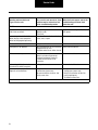
Service Codes
Group: 7P! (Codes 31, 32)
Type: Low Air Supply
System Mode
Condition
Possible Causes
(Listed in Likely Order of Occurrence)
Pressure check only
Pressure switch won’t
close (32)
- Compressor governor cut-out set too low.
- Air dryer needs service.
- Pressure switch unplugged.
- Open or broken line from supply tank to Pneumatic Control Unit.
- Crimped or plugged line from supply tank to Pneumatic Control Unit.
- Faulty pressure switch.
- Faulty compressor.
Supply Tank pressure too
low (32)
- Governor cut-in too low.
- Faulty compressor.
- Leaking lines.
Pressure switch failed
closed (31)
- Wiring to pressure switch shorted together.
- Faulty pressure switch.
Air Pressure Check
The Tire Pressure Control System is not continuously
pressurized; pressure checks occur on a periodic basis.
During tire pressure checks, the system delivers compressed
air to each channel for approximately two seconds while
monitoring the pressure in that channel.
The components that can cause the pressure switch to remain
open include:
•
Air dryer needs service.
•
Pressure switch unplugged or damaged wire
harness.
•
Faulty pressure switch.
•
Faulty compressor.
Code Description
•
Open or broken line from supply tank to Pneumatic
Control Unit.
Group 7P! displays if the system air pressure supply is too
low to perform a valid tire pressure check.
•
Crimped or plugged line from supply tank to Pneumatic Control Unit.
•
Faulty Electronic Control Unit.
This may occur because the pressure switch will not close
(inadequate air supply, code 32) or because the pressure
switch or its wiring is shorted, allowing the actual supply
pressure to be lower than anticipated by the system.
Note: To assure a nominal compressor output, code 32 will
not be set unless the pressure switch does not close for
a preset period while the vehicle is being driven at a
speed of over 20 mph.
39
To identify the root cause of the problem, connect the
diagnostic tool (see Diagnostics Section for test equipment
and descriptions) and follow the procedure in the 7P!
Troubleshooting Tree.
See "Troubleshooting Tips" for general guidelines on system
diagnostics.
Service Codes
Low Air Supply (Codes 31, 32)
Use diagnostic tool to determine type of fault.
Pressure
switch failed. Open or
closed?
Open
Is the governor
cutout pressure set
at 120-125 psig?
Verify wiring:
Switch off ignition.
Disconnect ECU harness connector and
supply tank pressure switch connector.
Check for shorts between ECU harness
connector pins G3 and K2.
Yes
No
Is the pressure
switch plugged in?
Repair harness
and retest.
Yes
Is there a
short?
Yes
No
Using the diagnostic tool, verify
pressure switch operation.
No
Replace pressure
switch and retest.
Does the
pressure switch
close above 110
psi?
No
Group: 7P! (Codes 31, 32)
Closed
Reset governor cutout
pressure and retest system.
Refer to Service Manual
Plug in pressure switch
and retest system.
Refer to Service Manual
Verify wiring:
Switch off ignition.
Disconnect ECU harness connector and
supply tank pressure switch connector.
Verify continuity between ECU harness
connector pin G3 and pressure switch
harness connector PRESS SW wire.
Verify other press switch wire is grounded.
Yes
Verify air system capacity by checking
supply tank pressure buildup time.
Are
connections
OK?
Repair vehicle air supply
system and retest.
Refer to Service Manual
No
Does the
supply tank build
up pressure?
Yes
No
Repair
harness and
retest.
Yes
Replace pressure switch
and retest system.
Refer to Service Manual
Service code is not active. Reverify
flowchart steps and wait for fault to reoccur.
40
Service Codes
Group: 8P! (Code 35)
Type: Atmospheric
System Mode
Condition
Possible Causes
(Listed in Likely Order of Occurrence)
Pressure check only
Pneumatic Control Unit
pressure out of range
- Faulty PCU Sensor.
- Faulty Pneumatic Control Unit.
- Faulty Electronic Control Unit.
Air Pressure Check
Code Description
The Tire Pressure Control System is not continuously
pressurized; pressure checks occur on a periodic basis.
During tire pressure checks, the system delivers compressed
air to each channel for approximately two seconds while
monitoring the pressure in that channel.
When the system measures tire pressures it also uses the
pressure sensor in the PCU to read atmospheric pressure.
Group 8P! displays if the atmospheric pressure reading is out
of range.
The components that can cause a group 8P! to be set include:
•
Faulty PCU Sensor or wiring.
•
Faulty Pneumatic Control Unit.
•
Faulty Electronic Control Unit (ECU).
To identify the root cause of the problem, connect the
diagnostic tool (see Diagnostics Section for test equipment
and descriptions) and follow the procedure in the 8P!
Troubleshooting Tree.
See "Troubleshooting Tips" for general guidelines on system
diagnostics.
41
Service Codes
Atmospheric (Code 35)
Using the diagnostic tool, read
the atmospheric pressure.
Is the reading
between 8 and 20
psia?
No
Is any audible air
flowing through the
PCU?
Yes
Yes
Service code is not active.
Reverify flowchart steps
and wait for fault to reoccur.
See service code No Code
for audible air leak in PCU.
No
See service code 5C! PCU sensor
and follow troubleshooting chart.
Group: 8P! (Code 35)
42
Service Codes
Group: 9P! (Codes 36, 37, 38)
Type: Inflate Trend
System Mode
Condition
Possible Causes
(Listed in Likely Order of Occurrence)
Channel inoperative
Loss of channel pressure in
inflate mode
- Damaged or leaking tire.
- Leaking lines.
- Leaking seals.
- Leaking wheel valve.
- Faulty Pneumatic Control Unit.
- Faulty Electronic Control Unit.
Code Description
Group 9P! displays when system pressure is dropping while
in inflate mode. This can occur when air is leaking from the
tire(s) or the system more quickly than the compressor can
replace it. The air leak that is causing a code 9P! is often audible. Codes 36, 37 and 38 designate the condition on the front,
rear or trailer channel respectively.
The air leak can be located either before or after the wheel
valve location. The components located before the wheel
valve that may cause a group 9P! include:
43
•
Leaking control lines between the PCU and the wheel
ends.
•
Leaking axle air seals.
•
Leaking wheel valve inlet lines or exhaust port.
Components located after the wheel valve that may cause a
code 9P! include:
•
Tire damage.
•
Rim leaks.
•
Valve stem leaks.
•
Leaking air lines from the wheel valve.
•
Faulty wheel valve.
To identify the root cause of the problem, connect the
diagnostic tool (see Diagnostics Section for test equipment
and descriptions) and follow the procedure in the 9P!
Troubleshooting Tree.
See "Troubleshooting Tips" for general guidelines on system
diagnostics.
Service Codes
Group: 9P! (Codes 36, 37,
38)
Inflate Trend (Codes 36, 37, 38)
Using the diagnostic tool, check
faults to identify the faulty channel:
Front (36)
Rear (37)
Trailer (38)
Is there a
damaged tire on
the identified
channel?
Yes
Repair tire and retest system.
No
Initiate inflate mode on the faulty channel.
Are there any
leaks in the
channel’s control
lines or seals?
Is there a leaking
hose between a tire
and wheel valve?
Yes
Yes
Repair leak and retest.
Replace the hose and
retest the system.
No
Replace PCU and retest.
No
Is air leaking
out the PCU vent
port?
Is a wheel valve
leaking through the
valve exhaust?
Yes
Yes
Replace the wheel valve
and retest the system.
Note: While replacing the PCU, pay
particular attention to possible air
line contamination (e.g., oil, water,
particles) which may suggest further
air system maintenance needs.
No
No
Service code is not active. Reverify
flowchart steps and wait for fault to reoccur.
44
Service Codes
Group: 10P! (Codes 41, 42, 43)
Type: Tire Leak (Confirm)
System Mode
Condition
Possible Causes
(Listed in Likely Order of Occurrence)
Inflate only
Channel confirmation
failure
- Damaged or leaking tire.
- Leaking line between wheel valve and tire.
- Air passage restriction.
- Wheel Valve shut off failure.
Air Pressure Check
The Tire Pressure Control System is not continuously
pressurized; pressure checks occur on a periodic basis.
During tire pressure checks, the system delivers compressed
air to each channel for approximately two seconds while
monitoring the pressure in that channel.
Code Description
Group 10P! code indicates that the system is unable to
confirm that tires on a given channel are able to sustain the
target pressure when the channel is depressurized. After any
change of pressure on a given channel, the Tire Pressure
Control System will return to that channel to confirm, or
"double-check" the new pressure before returning to the
periodic check interval. If the pressure is not the same, or
more than the last reading, the system will inflate again, and
then reconfirm that channel. After 7 - 10 confirmation
attempts, the system will log a 10P! code, and complete
operations on any remaining channel. It will then illuminate
the "check tires" warning (or code 10P! on the OCP), and the
appropriate channel indicator and continuously pressurize the
subject channel to inflate the tire(s) and sustain the tire
pressure. In this manner, the system will determine whether
the failure to confirm was due to tire or air line leakages
(codes 41, 42, and 43 on front, rear, and trailer respectively)
or failure of the wheel valve to properly close.
Note: Leaks from the tire(s) may be noted after the truck has
been idle overnight, as the tire(s) lose(s) air when the
truck is off and the system inoperative. By observing
the time required to achieve normal tire pressures after
starting the vehicle, many tire punctures can be identified well before the tire incurs non-repairable damage.
45
A confirmation failure can be caused by:
•
Damaged or leaking tire(s).
•
Leaking air line between the wheel valve and tire.
•
Air passage restriction between the PCU and the
wheel valve.
•
Wheel valve contamination or failure.
To identify the root cause of the problem, connect the
diagnostic tool (see Diagnostics Section for test equipment
and descriptions) and follow the procedure in the 10P!
Troubleshooting Tree.
See "Troubleshooting Tips" for general guidelines on system
diagnostics.
Service Codes
Tire Leak (Confirm) (Codes 41, 42, 43)
Stop vehicle and connect the
diagnostic tool to the system.
Group: 10P! (Codes 41,
42, 43)
Identify affected channels:
Front (41)
Rear (42)
Trailer (43)
Tire or air line leak
Spray soap solution on tires, bead area,
wheel valve and wheel valve hose.
Repair all leaks and perform checkout test.
46
Service Codes
Group: 11P! (Codes 44, 45, 46)
Type: Tire Leak (Imbalance)
System Mode
Condition
Possible Causes
(Listed in Likely Order of Occurrence)
Channel only checks
pressure
Tire pressure lower on one
tire than others on same
channel
- Minor tire leakage at start-up (leaked down overnight).
- Severe tire damage or leaks.
- Leaking lines.
- Contaminated wheel valve filters.
- Restricted tire valve stem.
- Leaking seals.
- Leaking wheel valve.
- Crimped or restricted control lines.
Air Pressure Check
The Tire Pressure Control System is not continuously
pressurized; pressure checks occur on a periodic basis.
During tire pressure checks, the system delivers compressed
air to each channel for approximately two seconds while
monitoring the pressure in that channel.
Using a tire pressure gauge to manually compare tire pressures on the indicated channel will allow you to identify the
specific tire involved. Very slow leaks may require that you
allow the vehicle sit overnight for sufficient air loss to occur.
To identify the root cause of the problem, connect the
diagnostic tool (see Diagnostics Section for test equipment
and descriptions) and follow the procedure in the 11P!
Troubleshooting Tree.
Code Description
Group 11P! indicates that pressure imbalance may exist
between the tires on the front (44), rear (45), or trailer (46)
channel after the system has achieved the target pressure.
This code can be caused by:
47
•
Damaged tire(s) - (tires will continue to lose air after
the vehicle is shut off).
•
Leaking air lines between the wheel valve and tire (tires will continue to lose air after the vehicle is shut
off).
•
Plugged or contaminated wheel valve filter(s) - one
tire of an axle group will deflate slower than others
and 11P! will be set after completion of the deflate
sequence due to one tire being higher in pressure.
•
Leaking air lines between the PCU and wheel valve tires may not exhibit actual imbalance; air line leaks
between PCU and wheel valve resulted in pneumatic
signature which imitated the fault.
See "Troubleshooting Tips" for general guidelines on system
diagnostics.
Service Codes
Tire Leak (Imbalance) (Codes 44, 45, 46)
Use diagnostic tool to verify proper vehicle configuration selection.
Using the diagnostic tool, identify the faulty channel:
Front (44)
Rear (45)
Trailer (46)
Manually check the tire pressures at
the wheel valves on the faulty channel.
Are any wheel
readings low?
Yes
No
Yes
Group: 11P! (Codes 44,
45, 46)
Check for a blocked wheel valve
exhaust or plugged wheel valve filter.
Make repairs to faulty components and
recheck the system.
Refer to Service Manual
Check the following:
Tire Damage
Wheel valve filter
Air line leaks
Wheel seal air leaks
Wheel valve leaks
Repair faulty components and recheck the system.
Refer to Service Manual
Are any wheel
readings high?
No
Place the channel into the inflate mode and check for audible leaks.
Place channel in
normal mode.
Make repairs to faulty
components and recheck system.
Refer to Service Manual
Yes
Is there
an audible leak?
(Also check axle
vents.)
Does wheel
valve close?
No
Place the channel into the hold mode and
check for leaks using a soap solution if
necessary to locate the source of the leak.
Yes
Check the system for
kinked lines. Repair
faulty components and
recheck the system.
Refer to Service
Manual
No
Is leak found?
No
Replace the wheel valve
and recheck system.
Refer to Service Manual
Yes
Make repairs to faulty components and recheck system.
Refer to Service Manual
48
Service Codes
Group: 12P! (Codes 61, 62, 63, 64, 65, 66)
Type: Wheel Valve Shut Off
System Mode
Condition
Possible Causes
(Listed in Likely Order of Occurrence)
Normal Operation
Loss of pressure during
shut off
- Wheel Valve shut off failure.
- Air passage restriction.
Air Pressure Check
Code Description
The Tire Pressure Control System is not continuously
pressurized; pressure checks occur on a periodic basis.
During tire pressure checks, the system delivers compressed
air to each channel for approximately two seconds while
monitoring the pressure in that channel.
Group 12P! code indicates that the system is unable to
confirm that tires on a given channel are able to sustain the
target pressure when the channel is depressurized. After any
change of pressure on a given channel, the Tire Pressure
Control System will return to that channel to confirm, or
"double-check" the new pressure before returning to the
periodic check interval. If the pressure is not the same, or
more than the last reading, the system will inflate again, and
then reconfirm that channel. After 7 - 10 confirmation
attempts, the system will log a 12P! code, and complete
operations on any remaining channel. The system will classify
the loss of air due to wheel valve closure as minor (codes 61,
62, and 63 on front, rear, and trailer respectively) or major
(codes 64, 65, and 66 on front, rear, and trailer respectively).
Note: Leaks from the tire(s) may be noted after the truck has
been idle overnight, as the tire(s) lose(s) air when the
truck is off and the system inoperative. By observing
the time required to achieve normal tire pressures after
starting the vehicle, many tire punctures can be
identified well before the tire incurs non-repairable
damage.
A confirmation failure can be caused by:
•
Damaged or leaking tire(s).
•
Leaking air line between the wheel valve and tire.
•
Air passage restriction between the PCU and the
wheel valve.
•
Wheel valve contamination or failure.
To identify the root cause of the problem, connect the
diagnostic tool (see Diagnostics Section for test equipment
and descriptions) and follow the procedure in the 10P!
Troubleshooting Tree.
See "Troubleshooting Tips" for general guidelines on system
diagnostics.
49
Service Codes
Group: 12P! (Codes 61,
62, 63, 64, 65, 66)
Wheel Valve Shut Off
(Codes 61, 62, 63, 64, 65, 66)
Stop vehicle and connect the
diagnostic tool to the system.
Which codes
are identified?
Codes 64, 65, 66
Codes:
Front (64)
Rear (65)
Trailer (66)
Wheel valve closure (major)
Codes 61, 62, 63
Codes:
Front (61)
Rear (62)
Trailer (63)
Wheel valve closure (minor)
Check airflow and look for restrictions
between the wheel valve and PCU.
Replace wheel valve and
perform checkout test.
No
Were
restrictions
found?
Yes
Repair restrictions and
perform checkout test.
50
Service Codes
Code: No Code
Type: Miscellaneous
Although the Tire Pressure Control System is self-diagnosing,
there are some problems that may not trigger a service code.
The following chart lists these conditions along with possible
causes and solutions:
Condition
Operating problems that do not
trigger a service code.
Possible Causes*
Since a service code was not set, these
conditions may be universal and not
call for a troubleshooting routine.
Service
Where fault codes appear, refer to the
troubleshooting procedures listed
under that code.
DRIVER INTERFACE (DDM or OCP)
Intermittent Driver Interface operation.
Intermittent ground or power connection Follow troubleshooting for 4C! group.
to Driver Interface or Electronic Control
Unit.
No operation (blank display).
- Fuses.
- Faulty ground or power connection.
- Check fuses.
- Repair power/ground.
Blank Driver Interface.
- No power to Driver Interface.
- Bad ground to Driver Interface.
- Bad switched ignition line to Driver
Interface.
- Faulty Driver Interface.
- Voltage out of range (9-18 volts).
Follow troubleshooting for 4C! group.
Operator Control Panel display is always
dim and no backlighting on Operator
Control Panel buttons.
Lamp 2 wire is disconnected. It should
be grounded for "bright" and tied to +12V
for "dim" and backlight.
See wiring schematic or Installation
Guide.
System loses programmed tire
pressure settings.
- Intermittent connection at config
connector.
- Improperly followed programming
procedure.
- Faulty Electronic Control Unit.
- See wiring schematic.
- Reference programming procedure.
- Replace Electronic Control Unit.
No display of pressures on Operator
Control Panel.
Operator Control Panel is in Quiet Mode. Refer to "Select Key" in section 3 of
Operator Instructions.
No display of pressures and no
apparent inflate or deflate.
Pressure switch not closed.
Follow troubleshooting for 7P! group.
ECU left in DIAGNOSTIC mode.
Move vehicle > 5mph.
* Possible causes are listed in order of likely occurrence.
51
Service Codes
Condition
Operating problems that do not
trigger a service code.
Possible Causes*
Since a service code was not set, these
conditions may be universal and not
call for a troubleshooting routine.
Service
Where fault codes appear, refer to the
troubleshooting procedures listed
under that code.
Display shows tires at higher pressure
than target, yet system does not attempt
to deflate. No apparent inflate or deflate.
Tire pressure rises due to temperature
are not bled off by the Tire Pressure
Control System. This is normal operation.
System will only initiate a deflate if a
mode with a lower target pressure than
current target is selected.
Pressure imbalance (tires on same
channel at different pressures).
- Defective hose.
- Clogged filters.
Follow troubleshooting for 11P! group.
No inflate or deflate of particular tire.
Valve stem core not removed on tire.
Remove hose from tire valve stem and
remove core. Replace hose.
Inaccurate tire pressures.
- Leaking control lines.
- Faulty pressure transducer.
Follow troubleshooting for 8P! and 11P!
group.
- Incorrect config. connector or bad
connection.
- Faulty Electronic Control Unit.
See wiring schematic.
Air bleeding from rear axle vents.
Air Seal degradation.
Refer to Service Manual.
Tires fail to deflate when lower
pressures are requested.
Pneumatic system problem.
Follow troubleshooting for 3P! group.
Leaking tires.
- Damaged tire.
- Loose connection between wheel
valve and tire.
- Loose/leaking tire valve stem.
- Faulty wheel valve.
Refer to Service Manual.
Air bleeding (audible) through
Pneumatic Control Unit when ignition is
turned off.
Wheel valve is leaking back through
control lines.
Identify tire with low pressure and
determine obstruction or replace wheel
valve.
TIRE PRESSURE
* Possible causes are listed in order of likely occurrence.
52
No Code
AIR LEAKS
Service Codes
Condition
Operating problems that do not
trigger a service code.
Possible Causes*
Since a service code was not set, these
conditions may be universal and not
call for a troubleshooting routine.
Service
Where fault codes appear, refer to the
troubleshooting procedures listed
under that code.
Apparent continuous operation, or
slow inflates or deflates.
- Tire(s) leakage.
- Between mode.
- Trend fault.
Follow troubleshooting for 4P!, 9P!, and
10P! group.
System stopped in middle of inflate or
deflate (display shows completion
before reaching targeted pressures).
Intermittent Pneumatic Control Unit
sensor, short, or open.
Follow troubleshooting for 5C! group.
Wheel end oil leak.
Faulty air or oil seal.
Refer to Service Manual.
Trailer present, not detected.
- Disconnected trailer air line connector. Refer to Service Manual.
- Clogged trailer air lines.
- Crimped control line on trailer channel.
Trailer detected, not present.
- Trailer connector on tractor side
doesn't seal when disconnected.
- Leaking line between Pneumatic
Control Unit and trailer air line
connector.
Refer to Service Manual.
High reading (>100 psi) on trailer
channel with no trailer connected.
Leaking trailer connector.
Refer to Service Manual.
No communications by the PC
diagnostic or handheld tool.
- No power to the communication
interface box (comm. box).
- No communications to comm. box.
- Faulty comm. box.
- Verify power to the communication
interface box (comm. box).
- Verify ECU connection to data link
(see wiring diagram).
- Try different comm. box.
OTHER
* Possible causes are listed in order of likely occurrence.
53
Service Codes
This page intentionally left blank.
No Code
54
Service Procedures
Final System Checkout
Test Requirements
This test requires use of a diagnostic tool (PC or handheld)
to control and monitor the functions of the Spicer TPCS, and
an accurate tire pressure gauge.
Select Highway-Loaded. Upon successfully achieving
Highway-Loaded, verify tire pressures are within ± psig of
desired pressure. If significant tire imbalance exists, balance
should be achieved by using the system to generate a short
deflate, followed by re-inflating the tires, or by manually
adjusting.
Verify governor cut-out pressure: ________________________________________ (Acceptance criteria: 120-125 psig)
Verify the Pressure Switch cycles open & closed during inflation:
Yes
/
No
Use Diagnostic tool to verify proper configuration: ________________________________________________________
If downloadable configuration is used, verify proper pressure settings, speeds, etc. have been set.
Use Diagnostic tool to DISPLAY SERVICE CODES.
•
Clear any existing historical codes.
Use Diagnostic tool to PERFORM DIAGNOSTIC TESTS.
•
Select channel and "Pressure Check Tires and Hold" option to pressurize each individual channel. Check for air leaks;
record the initial pressure and then the stabilized pressure 10 seconds later.
System Pressure:
Front
Rear
Trailer
Initial Pressure
Pressure after 10 sec.
Acceptance criteria: Pressure should not drop.
•
Select item "Pneumatic Control Unit," then "Read Isolated PCU Vacuum" and record PCU vacuum. Next, individually
select each channel and record System Pressure while deflating:
Isolated PCU Vacuum
Front
Rear
Trailer
(PSIA)
(inHg)
(inHg)
(inHg)
(inHg)
Acceptance criteria: Isolated PCU < 22 inHg, Individual channels ±1 inHg of Isolated PCU
55
Service Procedures
Use Diagnostic tool to MONITOR SYSTEM.
•
Deflate the system by selecting Highway-Unloaded. Upon successfully achieving Highway-Unloaded, use pressure
gauge to verify tire pressures are within ±3 psig of desired pressure.
•
Select Highway-Loaded. Upon successfully achieving Highway-Loaded, use pressure gauge to verify tire pressures are
within ±3 psig of desired pressure.
•
Drive vehicle and verify diagnostic tool display coincides with vehicle speedometer. If not, recalibrate the pulse/mile
count in the "Modify System Data" section of the diagnostic tool.
Is the vehicle speed calibrated?
Yes
/
No
Use Diagnostic tool to DISPLAY SERVICE CODES.
•
Verify no codes have been set during checkout process (clear if necessary). Exit diagnostics.
Note: If any suspected issues arise, inflation and deflation to other mode settings is appropriate to aid diagnosis.
Final System Checkout
56
Service Procedures
Pneumatic Control Unit - Cleaning and Inspection
The following describes the procedure for disassembly,
cleaning, and inspection of the Spicer Tire Pressure Control
System Pneumatic Control Unit (P/N 673336, and 673316).
Components requiring replacement can be found in the
Illustrated Parts List (AXIP-0010).
CAUTION
Do not use cleaning solvents which are not compatible with
elastomer or rubber components. Use of Brake Cleaners, or
solvents containing Xylene or Methyl Ketone, is not
recommended.
1.
Remove unit from the vehicle (refer to Service
Manual AXSM-0010).
2.
Remove bottom cover plate screws (10e), cover
plate (10a), and gasket (10b). If the unit has a trailer
module, remove screws (10e), plate (10c), and
gasket (10d).
3.
All cartridges (8) are normally open units with the
exception of the supply channel (9) which is normally closed. Ensure the normally closed cartridge
(9) is reinstalled in the supply port following cleaning. The cartridges can be removed by pulling them
from the bottom of the PCU.
4.
If the unit is a 3-channel system, remove 6 solenoid
cover screws (3c) and 4 trailer module cover screws
(7c).
5.
Lift solenoid cover and trailer module cover together
to clear solenoids.
6.
Remove solenoids from operators by removing 9/16"
hex nuts on top of solenoids.
7.
Remove solenoid operators from PCU body using a
1" wrench on the brass base (13).
Note: All operators with the exception of the deflate operator
are 3 way (indicated by threaded port in top of part). Do
not mix deflate operator or its internal plunger (15) with
other operators, or plungers (14). Ensure that both Orings (11,12) in operator bases are not lost.
57
8.
Remove operator stem from base (13) on all operators using spanner wrench (16). If spanner wrench
is not available, double nutting the operator stem
(with the 9/16" hex nuts) will enable disassembly.
9.
Inspect condition of poppets (14,15) inside operator.
Note: Deflate plunger (15) is specific to the deflate operator,
and is identified by its solid metal top. If poppets
appear in good condition, thoroughly clean poppet and
operator assembly. Verify the absence of any "sticky"
residue from oil contamination.
10. Reassemble each operator with the base. Do not
install assemblies on PCU body until it is completely
cleaned.
11. Spray cleaning solvent on cartridge bores within
PCU body to remove debris and oil residue. Thoroughly dry cartridge bores prior to further assembly.
12. Replacing cartridges is not typically required;
however, it may be desirable to replace the 3 outer
O-rings on each or any individual cartridge. These
are standard nitrile O-rings and the sizes are
provided on the following page. Replacement
cartridges are available if required. See Illustrated
Parts List (AXIP-0010).
13. Lightly lube cartridge O-rings with silicone grease
and install cartridges in body, verifying that the one
normally closed cartridge (9) is installed in the
Supply (IN) port.
Note: Excess lube on piston O-rings can block hole from solenoid to top of piston. Be careful only to wipe lube on
O-rings. Do not pack grooves.
14. Install base gasket (10b), base cover plate (10a), and
screws (10e). If 3-channel Pneumatic Control Unit,
install gasket (10d), plate (10c), and screws (10e).
Torque screws 40 to 45 in. lbs.
15. Verify presence of O-rings in bases of solenoid
operator assemblies and reinstall operators onto
Pneumatic Control Unitbody. Verify 2-way operator
(solid metal top) is in Deflate location. Specific
location of other operators (3-way) is not important.
16. Install solenoids on operators verifying proper
location per labels on solenoids and Pneumatic
Control Unit body.
17. Carefully tuck solenoid wires in area between
transducer and solenoids while reinstalling the
solenoid covers.
Service Procedures
PCU - Cleaning and
Inspection
Note: It is necessary to position both covers on the body at
the same time.
18. Carefully tighten cover screws ensuring that wires
are not pinched between cover and body. Torque
screws 40 to 45 in. lbs.
19. Reinstall Pneumatic Control Unit in vehicle.
20. Conduct TPC system checkout to verify integrity of
cleaning/assembly.
58
Service Procedures
Solenoid Assembly and Cartridge
Typical Pneumatic Control Unit Assembly
Optional Trailer Channel
7a
7c
3c
6
3a
7b
3b
8
2
10d
1
8
10e
9
10b
10a
10e
59
10c
Service Procedures
Typical Solenoid Assembly
PCU Cleaning
& Inspection
16
Solenoid Assembly &
Cartridge
11
12
15
14
13
Typical Cartridge
PISTON 0-RING
(-114)
CARTRIDGE 0-RING
(-020)
60
Service Procedures
Service Guidelines
The Tire Pressure Control System requires normal maintenance much the same as other systems on the vehicle. Following are some general rules that apply to Tire Pressure
Control System service:
Clean and Dry Air Supply
The Spicer Tire Pressure Control System requires a constant
supply of clean dry air. An adequately sized and properly
maintained air dryer is critical for continued proper operation
of the Tire Pressure Control System. Even though the air dryer
may be working properly, moisture can accumulate in the
supply tank during normal operation due to the increase in air
consumption. It is important to drain the supply tank daily.
Draining the supply tank completely when the truck is not in
use will also help keep moisture under control.
Line Replacement and Routing
When replacing air lines, do not allow kinks, sharp bends or
stretching in order to tighten joints. If any tube or hose segment does not appear to fit easily, it could mean you are not
using the proper part or that you are not following service
procedures properly. Ensure that replacement lines are the
correct length and size. Be cautious of any contaminants (rubber flash, plastic particles, etc.) getting into the lines when
replacing them.
Each segment of the pneumatic system must be secured to
the vehicle frame or other installed line. After completing
assembly of each segment, use cable ties to anchor the segment at approximately 18" intervals.
CAUTION
Proper Tire Pressure Control System operation requires
correct air line diameters and lengths for each channel.
Incorrect air line replacement can affect both performance
and operation of the system. Refer to the Tire Pressure Control System service manual for length and diameter information.
61
Joint Compounds and Fittings
Here are some important "DO's" and "DON'Ts" regarding the
use of thread sealant:
•
Do apply a thin coating of PTFE based compound on
male threads of pipe joints, tubing connections, and
other system fittings.
•
Don't use any compound on O-ring, compression, or
flare fitting connections. Instead, apply a thin coat of
silicone grease to O-rings and flares.
•
Don't use Teflon thread tape anywhere in the air
system. (Teflon tape shreds can become lodged in
valves and cause malfunctions.)
•
Do follow manufacturer recommended guidelines
when tightening fittings.
Service Procedures
Air Filter Change
prevent air loss (SAE 37 degree flare plug, 3/8" tube
size, 9/16-18 thread).
The "Air Filter Change" illustration shows the location of the air
filter in each wheel valve. This filter must be replaced whenever the tire or wheel valve is serviced. Use the illustration as
a reference in completing the air filter replacement as follows:
WARNING
Be sure to use appropriate eye and ear protection.
2.
Remove the adapter fitting from the tire port.
3.
Use a flat blade screwdriver to remove (unscrew
counterclockwise) the air filter from the wheel valve.
Discard the used air filter.
4.
Install a new air filter by pressing it straight into
wheel valve tire port.
5.
Clean the adapter, replace and lubricate the O-ring if
necessary and reinstall the adapter in the wheel valve
tire port. Tighten to 16-19 lbs. ft.
6.
Remove the plug and reinstall the tire hose assembly
to the adapter on the wheel valve tire port. Torque to
16-19 lbs. ft.
CAUTION
Do not crush the air filter when installing adjustable
straight thread O-ring adapters.
Note: Air filters should not be cleaned or reused. Always
replace with a new air filter.
1.
Working quickly to prevent air loss, remove the tire
hose assembly from the fitting on the tire port (nearest the tire fill valve) of the wheel valve. Plug hose to
Note: For installation of adjustable straight thread O-ring
adapters, follow instructions in the service manual to
prevent crushing the filter.
Adapter
Tire
Hose
Air Filter Change
Control Port
Air
Filter
Tire Port
Wheel
Valve
62
Service Procedures
Troubleshooting Wheel End Seals
Perform an air seal pressure check as follows (refer to
"Wheel End Seals" illustration).
1.
Connect a hose from a pressure reservoir, 2" ID x 12"
long with 2' long 3/8" hose (or equivalent volume),
to the inlet tube.
2.
Plug hub air port with a 3/8" pipe plug or 9/16-18
straight thread O-ring plug, as appropriate.
3.
Open the valve from the air supply line and stabilize
the pressure in the reservoir to 100 PSI minimum.
Close air supply valve. Rotate the hub assembly while
monitoring the pressure gauge. The pressure reading should
not drop more than 15 PSI in 20 seconds.
Note: If the air leakage exceeds 15 PSI in 20 seconds, the hub
may need to be rotated several times to ensure a
complete pressure seal.
If air leakage rate remains outside of accepted limit, locate
source of leak:
•
Loose Fittings.
•
Spindle/Sleeve Outer O-ring.
•
Air Seals.
Refer to the Service Manual for replacement procedure.
63
Service Procedures
Shop Air
Supply
Wheel End Seals
Wheel End Seals
Reservoir
2" I.D. Pipe, 12" Long
Air Port Plugged for Test
Oil Fill Plug
2' Long, 3/8" I.D. Hose
Air Seals
O-Ring
Backup Ring and O-Ring
O-Rings Required
on Hubs with Grooves
64
Service Procedures
Hose and Supply Tank Selection Chart
CAUTION
The following hose lengths and sizes are necessary
for correct TPCS operation.
Any deviations may cause the system to function incorrectly
and may reduce the ability to detect low tires.
Front Channel Plumbing Requirements
Standard Front (1 Axle)
Dual Front (2 Axle) Both Non-Driven
Dual Front (2 Axle) 1 Driven, 1 Non-Driven
Min. Tank Size
Main Run
Jounce
1400 in3
18' to 20' 5/8" OD
6' to 8' per axle 5/16" ID Only
(6 gal.)
21' to 23' 13/32" ID
6' to 8' per axle 5/16" ID Only
25' to 27' 1/2" OD
6' to 8' per axle 5/16" ID Only
1400 in3
18' to 21' 5/8" OD
6' to 8' per axle 5/16" ID Only
(6 gal.)
21' to 25' 13/32" ID
6' to 8' per axle 5/16" ID Only
25' to 29' 1/2" OD
6' to 8' per axle 5/16" ID Only
2800 in3
18' to 21' 5/8" OD
6' to 8' per axle 5/16" ID Only
(12 gal.)
21' to 25' 13/32" ID
6' to 8' per axle 5/16" ID Only
25' to 29' 1/2" OD
6' to 8' per axle 5/16" ID Only
Min. Tank Size
Main Run
Jounce
1400 in3
15' to 17' 5/8" OD
7' to 9' per axle 5/16" ID Only
(6 gal.)
18' to 20' 13/32" ID
7' to 9' per axle 5/16" ID Only
21' to 24' 1/2" OD
7' to 9' per axle 5/16" ID Only
1400 in3
14' to 17' 5/8" OD
7' to 9' per axle 5/16" ID Only
(6 gal.)
16' to 20' 13/32" ID
7' to 9' per axle 5/16" ID Only
18' to 24' 1/2" OD
7' to 9' per axle 5/16" ID Only
2800 in3
16' to 20' 13/32" ID
5' to 7' per axle 5/16" ID Only
(12 gal.)
18' to 24' 1/2" OD
5' to 7' per axle 5/16" ID Only
Rear Channel Plumbing Requirements
Single Rear (1 Axle)
Tandem Rear (2 Axle)
Tridem Rear (3 Axle)
65
Service Procedures
Trailer Channel Plumbing Requirements
(Tractor) PCU to Glad Hand*
Min. Tank Size
Main Run
N/A
16' to 22' 5/8" OD
Jounce
19' to 25' 13/32" I D
22' to 30' 1/2" OD
Single Trailer (2 to 3 Axles)
Dual Trailers (4 to 5 Axles)
35' to 40' 1/2" OD
7' to 9' per axle 5/16" ID Only
(6 gal.)
40' to 50' 5/16" ID
7' to 9' per axle 5/16" ID Only
2800 in3
60' to 85' 1/2" OD
7' to 9' per axle 5/16" ID Only
(12 gal.)
75' to 100' 5/16" ID
7' to 9' per axle 5/16" ID Only
Hose Selection Chart
1400 in3
Notes:
1.
Air line sizes shown with an outer diameter
measurement are for DOT approved nylon air brake
tubing meeting SAE J844. Air line sizes shown with
an inner diameter measurement are for DOT
approved reinforced rubber hose meeting SAE
J1402.
2.
For Pneumatic Control Unit to Glad Hand plumbing
when using a coiled hose, include the coiled hose
length in the overall measurement. Example: A 22'
coil air hose with a 15' working length is actually 22'
in length.
3.
Wire braid hose diameter is inside diameter (I.D.).
Nylon hose diameter is outside diameter (O.D.).
66
Wire Harness
Connector Illustrations (All views shown looking into connector)
Harness Connectors
OCP
Diagnostics
ECU
9-Pin
5 6
8 9 10
J1939 / Can Link
A B C D E
A B C D E
A B C D E
F G H J K
F G H J K
F G H J K
DDM Load Switch
3
2
1
D
E
F
6-Pin
C
B
B
A
A
E
J
DDM Terrain Switch
DDM Display
5
6
4
7
2A
3
8
2B
2
9
1
10
7
9
7
9
4
1
4
1
5A
2A
5A
5B
2B
5B
6
3
6
3
8
10
8
10
Harness and Component Connectors
Harness
Pressure Switch
Component
A
B
B
A
A
B
B
A
Speed Sensor
PCU Sensor
A
B
A
B
C
C
Configuration
A
B
A
B
D
D
C
C
B
A
C
B
PCU Sensor
Connector
C
PCU Sensor
A
A
PCU 10-way
K
B
C
D
E
H
G
F
PCU
Connector
Pneumatic
Control Unit
67
C
H
G
E
D
C
F
G
H
B
A
K
Wire Harness
Electrical Schematic
Note: Schematic is shown for "point- to-point" troubleshooting only. Actual OEM implementations may vary with
bulkhead connectors, etc.
ECU Connector
SPEED A
SPEED B
SPEED F3
SPEED F2
SPEED SENSOR INPUT
or
CONDITIONED SPEED INPUT
COND SPEED
COND SPEED F1
DIMMER
DIMMER J1
DIMMER INPUT (0V= Dim, 12V = Bright)
Note: Not used with DDM.
BUZZER
BUZZER OUTPUT (5V, 25mA MAX)
PRESS SW
PRESS SW G3
PRESSURE
SWITCH INPUT
GROUND
COMM+
COMM+ K3
COMM-
COMM- J3
GND
POWER
LAMP
{
BUZZER D3
DRIVER
INTERFACE
Note: Actual connector may not be present.
See next page for options OCP or DDM.
Electrical Schematic
VEHICLE POWER PANEL
GROUND
GROUND K2
+VBATT
GND
LAMP
DASH
LAMPS
SWACC
POWER K1
15 A FUSE
IGNITION
SWITCH
9 PIN/6 PIN
POWER B/C
GROUND
J1708A C1
J1708B C2
J1939(+) A1
J1939(-) A2
J1939 SHIELD C3
F/A
J1708B
G/B
J1939+
A
J1939-
B
J1939 SHIELD
C
GROUND
CONFIG 1 G1
CONFIG 2 G2
A/E
J1708A
J1587
DIAGNOSTIC
J1939
COMMUNICATIONS
A
CONFIG 1
B
POWER
C
CONFIG 2
D
CONFIGURATION
SELECTION
Jumper plug may tie each config line to
POWER or GROUND to select config.
See configuration connectors for details.
PNEUMATIC CONTROLLER
A
F
H
SUPPLY SOL
B1
DEFLATE SOL B2
CONTROL SOL B3
STEER SOL D1
DRIVE SOL D2
TRAILER SOL E1
C
SUPPLY
B
DEFLATE
D
CONTROL
G
STEER
E
DRIVE
K
TRAILER
3 CHANNEL SYSTEMS ONLY
XDCR SIGNAL H1
XDCR VREF H2
C
C
B
B
A
A
PCU SENSOR
XDCR COMMON H3
68
Wire Harness
Driver Interface Options
Driver Display Module (DDM)
GROUND
4
POWER
5
COMM+
7
COMM-
6
3
Display
1
DIMMER
2
DIMMER
8
COMM+
DIMMER
7
COMM-
POWER
1
GROUND
GROUND
3
POWER
GROUND
9
LAMP/DIMMER
GROUND
Load Switch
10
2B
2B
Or
Operator Control Panel (OCP)
COMM+
9
COMM-
10
GROUND
6
POWER
5
LAMP/DIMMER
8
NO CONNECTION 7
69
GROUND
10
GROUND
9
GROUND
3
POWER
1
DIMMER
7
DIMMER
8
Terrain Switch
Wire Harness
Configuration Connections
Configuration Connections
CONFIG 0
HARNESS
CONNECTOR
GROUND
CONFIG 1
POWER
CONFIG 2
A
B
C
D
A
B
C
D
OR
WITH OPTIONAL TRAILER:
OR
CONFIG 1
HARNESS
CONNECTOR
GROUND
CONFIG 1
POWER
CONFIG 2
A
B
C
D
(BOTH STEERS NON-DRIVEN)
OR
A
B
C
D
WITH OPTIONAL TRAILER:
OR
CONFIG 2
HARNESS
CONNECTOR
GROUND
CONFIG 1
POWER
CONFIG 2
A
B
C
D
(1 STEER DRIVEN, 1 STEER NON-DRIVEN)
OR
A
B
C
D
WITH OPTIONAL TRAILER:
OR
CONFIG 3
HARNESS
CONNECTOR
GROUND
CONFIG 1
POWER
CONFIG 2
A
B
C
D
OR
A
B
C
D
WITH OPTIONAL TRAILER:
OR
CONFIG 4
HARNESS
CONNECTOR
GROUND
CONFIG 1
POWER
CONFIG 2
A
B
C
D
A
B
C
D
WITH OPTIONAL TRAILER:
OR
70
Wire Harness
Configuration Connections
CONFIG 5
HARNESS
CONNECTOR
GROUND
CONFIG 1
POWER
CONFIG 2
A
B
C
D
A
B
C
D
WITH OPTIONAL TRAILER:
OR
CONFIG 6
HARNESS
CONNECTOR
GROUND
CONFIG 1
POWER
CONFIG 2
A
B
C
D
A
B
C
D
CONFIG 7
HARNESS
CONNECTOR
GROUND
CONFIG 1
POWER
CONFIG 2
A
B
C
D
A
B
C
D
(Reserved)
(BOTH STEERS NON-DRIVEN)
OR
WITH OPTIONAL TRAILER:
OR
CONFIG 8
HARNESS
CONNECTOR
GROUND
CONFIG 1
POWER
CONFIG 2
A
B
C
D
A
B
C
D
(1 STEER DRIVEN, 1 STEER NON-DRIVEN)
OR
WITH OPTIONAL TRAILER:
OR
71
This page intentionally left blank.
For spec‘ing or service assistance, call 1-877-777-5360 or visit our website at www.dana.com
Dana Commercial Vehicle Products Group
3939 Technology Drive
Maumee, Ohio, USA 43537
www.dana.com
All applications must be approved by the Application Engineering Department. Specifications and/or design are subject to change without notice or obligation.
Printed in USA
AXTS-0020 04/07