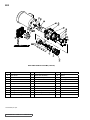
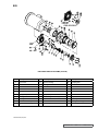
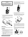
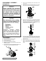
1
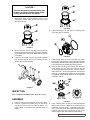
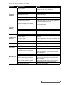
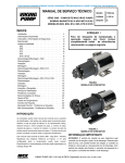
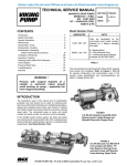
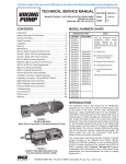
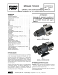
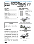
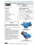
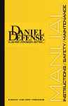
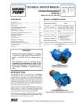
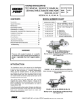
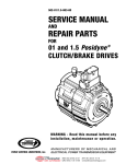
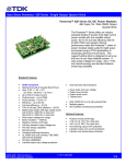
Electronic copies of the most current TSM issue can be found on the Viking Pump website at www.vikingpump.com
TECHNICAL SERVICE MANUAL
CMD SERIES
COMPOSITE MAG DRIVE PUMPS
MODELS E02, E05, E12, E25, E75 AND E125
CONTENTS
Introduction . . . . . . . . . . . . . . . . . . . . . . . .1
Special Information . . . . . . . . . . . . . . . . . . . .1
Safety Information . . . . . . . . . . . . . . . . . . . . 2
Maintenance . . . . . . . . . . . . . . . . . . . . . . .3
Exploded Views . . . . . . . . . . . . . . . . . . . . . 4
E02 . . . . . . . . . . . . . . . . . . . . . . . . . . .4
E05 . . . . . . . . . . . . . . . . . . . . . . . . . . .5
E12 . . . . . . . . . . . . . . . . . . . . . . . . . . .6
E25 . . . . . . . . . . . . . . . . . . . . . . . . . . .7
E75 and E125 . . . . . . . . . . . . . . . . . . . . .8
Disassembly/Assembly - E02 . . . . . . . . . . . . . . 9
Disassembly . . . . . . . . . . . . . . . . . . . . . .9
Inspection . . . . . . . . . . . . . . . . . . . . . . 10
Assembly . . . . . . . . . . . . . . . . . . . . . . .10
Disassembly/Assembly - E05 and E12 . . . . . . . . . 12
Disassembly . . . . . . . . . . . . . . . . . . . . . 12
Inspection . . . . . . . . . . . . . . . . . . . . . . 13
Assembly . . . . . . . . . . . . . . . . . . . . . . .13
Disassembly/Assembly - E25, E75 and E125 . . . . . 15
Disassembly . . . . . . . . . . . . . . . . . . . . . 15
Inspection . . . . . . . . . . . . . . . . . . . . . . 16
Assembly . . . . . . . . . . . . . . . . . . . . . . .16
Inspection and Wear Limits . . . . . . . . . . . . . . 18
Service and Replacement Limits . . . . . . . . . . . . 18
Troubleshooting Chart . . . . . . . . . . . . . . . . . 19
Bolt Torque Recommendations . . . . . . . . . . . . . 20
ATEX Directive . . . . . . . . . . . . . . . . . . . . . 21
Temperature Class and Max. Liquid Temperatures . . 21
Sample Tag . . . . . . . . . . . . . . . . . . . . . . . 22
Normal Operation . . . . . . . . . . . . . . . . . . . 23
Expected Malfunction . . . . . . . . . . . . . . . . . 23
SECTION
TSM 344
PAGE
1 OF 24
ISSUE
G
ATTENTION !
To ensure safe handling and operating
situations, please thoroughly review
all of the warnings listed on the
following page.
FIGURE 1
MODEL E05 WITH MOTOR
INTRODUCTION
The illustrations used in this manual are for identification
purposes only and cannot be used for ordering parts. Obtain
a parts list from the factory or a Viking representative. Always
give a complete name of the part, part number and material
with the model number and serial number of pump when
ordering repair parts. The unmounted pump or pump unit
model number and serial number are on the nameplate.
This manual deals only with CMD Series Composite Mag
Drive Pumps. Refer to Figures 1 through 47 for general
configuration and nomenclature used in this manual. Pump
specifications and recommendations are listed in Catalog
Section 344.
FIGURE 2
MODEL E25 WITH MOTOR
SPECIAL INFORMATION
ROTATION: Shaft rotation determines which port is suction
and which is discharge. Viewed from shaft end, with clockwise
rotation, the right port is suction and left port is discharge.
With counterclockwise rotation, the left port is suction and
right port is discharge.
VIKING PUMP, INC. • A Unit of IDEX Corporation • Cedar Falls, IA 50613 USA
SAFETY INFORMATION
INCORRECT INSTALLATION, OPERATION OR MAINTENANCE OF EQUIPMENT MAY CAUSE SEVERE
PERSONAL INJURY OR DEATH AND/OR EQUIPMENT DAMAGE AND MAY INVALIDATE THE WARRANTY.
This information must be read fully before beginning installation, operation or maintenance and must be
kept with the pump. All installation and maintenance must be undertaken by suitably trained or qualified
persons only.
Symbol
Legend :
!
!
Danger - Failure to follow the listed
precautionary measures identified by
this symbol may result in serious injury
or death.
DO NOT OPERATE PUMP IF:
– The front cover is not installed correctly.
WARNING
WARNING
– Any guards are missing or incorrectly installed.
– The suction or discharge piping is not connected.
!
DO NOT place fingers, etc. into the pumping chamber
or its connection ports or into any part of the drive train
if there is ANY possibility of the pump shafts being
rotated. Severe injury will occur.
!
DO NOT exceed the pumps rated pressure, speed, and
temperature, or change the system/duty parameters
from those for which the pump was originally supplied,
without confirming its suitability for the new duty.
!
INSTALLATION AND OPERATION OF THE PUMP
MUST ALWAYS COMPLY WITH HEALTH AND
SAFETY REGULATIONS.
!
Rare earth magnets used in couplings have
extremely strong magnetic fields capable of
changing performance or damaging items such as:
Pacemakers, Metal Implants, Watches, Computers
& Disks, and Credit Cards
WARNING
WARNING
WARNING
!
!
!
!
A device must be incorporated into the pump, system,
or drive to prevent the pump exceeding its stated duty
pressure. It must be suitable for both directions of
pump rotation where applicable. Do not allow pump
to operate with a closed/blocked discharge unless a
pressure relief device is incorporated. If an integral
relief valve is incorporated into the pump, do not allow
re-circulation through the relief valve for extended
periods.
The mounting of the pump or pump unit should be
solid and stable. Pump orientation must be considered
in relation to drainage requirements. Once mounted,
shaft drive elements must be checked for correct
alignment. Rotate pump shaft by at least one full
revolution to ensure smoothness of operation.
Incorrect alignment will produce excessive loadings
and will create high temperatures and increased noise
emissions. Do not use any drive arrangements which
cause sideloading of the drive shaft.
The installation must allow safe routine maintenance
and inspection (to check for leakage, monitor
pressures, etc) and provide adequate ventilation
necessary to prevent overheating.
ISSUE
G
PAGE 2 OF 24
DO NOT INSTALL THE PUMP INTO A SYSTEM
WHERE IT WILL RUN DRY (I.E. WITHOUT A
SUPPLY OF PUMPED MEDIA).
Pressure gauges/sensors are recommended, next
to the pump suction and discharge connections to
monitor pressures.
Caution must be taken when lifting the pump. Suitable
lifting devices should be used as appropriate. Lifting
eyes installed on the pump must only be used to lift
the pump, not pump with drive and/or baseplate. If
pump is baseplate mounted, the base plate must be
used for all lifting purposes. If slings are used for lifting,
they must be safely and securely attached. For weights
of bare shaft pumps refer to catalog.
DO NOT attempt any maintenance or disassembly of
the pump or pump unit without first ensuring that :
– The pump is fully isolated from the power source
(electric, hydraulic, pneumatic).
–The pumping chamber, relief valve and any
shaft seal support system are depressurized and
purged.
– Any temperature control devices (jackets, heattracing, etc) are fully isolated, that they are
depressurized and purged, and components are
allowed to reach a safe handling temperature.
!
!
!
!
SECTION TSM 344
Before operating the pump, be sure that it and all
parts of the system to which it is connected are clean
and free from debris and that all valves in the suction
and discharge pipelines are fully opened. Ensure that
all piping connecting to the pump is fully supported
and correctly aligned with its relevant connections.
Misalignment and/or excess loads will cause severe
pump damage.
Be sure that pump rotation is correct for the desired
direction of flow.
Completely assembled magnetic couplings will
not affect items listed above - only disassembled
components.
There are no known harmful effects of these
magnetic fields on the human body.
Warning - Safety instructions which
shall be considered for reasons of safe
operation of the pump or pump unit and/
or protection of the pump or pump unit
itself are marked by this symbol.
DO NOT attempt to dismantle a pressure relief valve
which has not had the spring pressure relieved or is
mounted on a pump that is operating. Serious personal
injury or death and/or pump damage may occur.
DO NOT loosen or undo the front cover, any
connections to the pump, shaft seal housings,
temperature control devices, or other components,
until sure that such action will not allow the unsafe
escape of any pressurized media.
Pumps and/or drives can produce sound power levels
exceeding 85 dB(A) under certain operating conditions.
When necessary, personal protection against noise
must be taken.
Avoid any contact with hot parts of pumps and/or
drives which may cause injury. Certain operating
conditions, temperature control devices (jackets, heattracing, etc.), bad installation, or poor maintenance
can all promote high temperatures on pumps and/or
drives.
SPECIAL INFORMATION (CONT’D)
DANGER !
PRESSURE RELIEF VALVES:
1. Viking pumps are positive displacement pumps and
must be provided with some sort of pressure protection.
This may be an inline pressure relief valve, a torquelimiting device, or a rupture disk, or other method.
NOTE: Pump can be operated in reverse direction for
short duration at low differential pressure to clean/flush
out lines.
2. If pump rotation is to be reversed during operation,
pressure protection must be provided on both sides
of the pump.
3. Pressure relief valves cannot be used to control pump
flow or regulate discharge pressure.
For additional information on pressure relief valves, refer
to Technical Service Manual TSM000 and Engineering
Service Bulletin ESB-31.
MAINTENANCE
Series CMD pumps are designed for long, trouble-free
service life under a wide variety of application conditions with
a minimum of maintenance. The following points will help
provide long service life.
Pumps that are mounted directly to the motor will need to be
removed from the mounting bracket to perform mechanical
seal maintenance or replacement.
CLEANING PUMP: Keep the pump as clean as possible.
This will facilitate inspection, adjustment, and repair work.
Before opening any Viking pump liquid
chamber (pumping chamber, reservoir,
relief valve adjusting cap fitting, etc.)
Be sure:
1. That any pressure in the chamber has
been completely vented through the
suction or discharge lines or other
appropriate openings or connections.
2.That the driving means (motor,
turbine, engine, etc.) has been
“locked out” or made non-operational
so that it cannot be started while
work is being done on pump.
3.That you know what liquid the
pump has been handling and the
precautions necessary to safely
handle the liquid. Obtain a material
safety data sheet (MSDS) for the
liquid to be sure these precautions
are understood.
Failure
to
follow
above
listed
precautionary measures may result in
serious injury or death.
STORAGE: If pump is to be stored, or not used for six
months or more, the pump must be drained and a light coat
of light oil must be applied to all internal pump parts.
Apply grease to the pump shaft extension. Viking suggests
rotating pump shaft by hand one complete revolution every
30 days to circulate the oil. Tighten all pump assembly bolts
before putting the pump in service after being stored.
CMD
-
Series:
Composite Mag Drive
E02
Model:
E02
E05
E12 *
E25 *
E75 *
E125 *
E
L
V
F
-
X
Materials/Ports:
O-Rings:
Options:
E = ETFE, FNPT
(E02, E05, E12)
V=Viton®
A = Bearing Flush Ports
E=EPDM
B = Combination of Options A and N
B = ETFE, ISO 7-1
(E02, E05, E12)
F = ETFE, Flange
(E25, E75, E125)
Bearings:
L = Carbon Graphite
B=Graphite-Impregnated
Silicon-Carbide
* Export license required under U.S. Export
Administration ECCN 28350 and 28999.
N = Without Drive Magnet
X = Complete Pump (No Options)
Mounting Arrangement:
F = NEMA 56C (E02, E05, E12, E25)
O = NEMA 143TC-182C (E05, E12, E25, E75, E125)
R = NEMA 182TC-184TC (E75, E125)
H = IEC B34 63 (E02, E05, E12)
K = IEC B34 80 (E02, E05, E12)
P = IEC B14 100/112 (E25, E75, E125)
Y = No Motor Mount Kit (E02, E05, E12, E25, E75, E125)
Viton® is a registered trademark of DuPont Performance Elastomers.
SECTION TSM 344
ISSUE
G
PAGE 3 OF 24
E02
EXPLODED VIEW OF E02 PUMP (TYPICAL)
Item
Description
Item
2
Drive Screw
13
Drive Gear Assembly *
23
Washer
3
Bolts
14
Center Housing
24
Drive Magnet
4
Washers
15
O-Ring, Containment Canister *
25
Coupling Hub
5
Front Cover
16
Bolts
26
Set Screw
6
O-Ring, Cover *
17
Washers
27
Screws
7
Bolts
18
Adapter, Canister
29
Bolts
9
O-Ring, Compression *
19
Containment Canister
30
Washer
10
Bearing *
20
Adapter, Spool
31
Adapter, Motor
11
Housing Liner *
21
Driven Magnet Assembly
12
Idler Gear Assembly *
22
Bolts
* Recommended spare parts.
SECTION TSM 344
ISSUE
G
PAGE 4 OF 24
Description
Item
Description
E05
EXPLODED VIEW OF E05 PUMP (TYPICAL)
Item
Description
Item
Item
Description
2
Drive Screw
14
Description
Center Housing
25
Coupling Hub
3
Bolts
15
O-Ring, Containment Canister *
26
Set Screw
4
Washers
16
Bolts
27
Screws
5
Front Cover
17
Washers
28
Nut Plate
6
O-Ring, Cover *
19
Containment Canister
29
Bolts
9
O-Ring, Compression *
20
Adapter, Spool
30
Washer
10
Bearing *
21
Driven Magnet Assembly
31
Adapter, Motor
11
Housing Liner *
22
Bolts
32
Retaining Plate
12
Idler Gear Assembly *
23
Washer
33
O-Ring, Drain Plug *
13
Drive Gear Assembly *
24
Drive Magnet
34
Drain Plug
* Recommended spare parts.
SECTION TSM 344
ISSUE
G
PAGE 5 OF 24
E12
EXPLODED VIEW OF E12 PUMP (TYPICAL)
Item
Description
Item
2
Drive Screw
14
3
Bolts
4
5
Description
Item
Description
Center Housing
25
Coupling Hub
15
O-Ring, Containment Canister *
26
Set Screw
Washers
16
Bolts
27
Screws
Front Cover
17
Washers
28
Nut Plate
6
O-Ring, Cover *
19
Containment Canister
29
Bolts
9
O-Ring, Compression *
20
Adapter, Spool
30
Washer
10
Bearing *
21
Driven Magnet Assembly
31
Adapter, Motor
11
Housing Liner *
22
Bolts
32
Retaining Plate
12
Idler Gear Assembly *
23
Washer
33
O-Ring, Drain Plug *
13
Drive Gear Assembly *
24
Drive Magnet
34
Drain Plug
*  Recommended spare parts.
SECTION TSM 344
ISSUE
G
PAGE 6 OF 24
E25
EXPLODED VIEW OF E25 PUMP (TYPICAL)
Item
Description
Item
Description
Item
Description
2
Drive Screw
16
Bolts
28
Nut Plates
3
Bolts
17
Washers
29
Bolts
4
Washers
18
Adapter, Motor
30
Washer
5
Front Cover
19
Containment Canister
31
Flange Gaskets
6
O-Ring, Cover *
20
Adapter, Spool
32
Mounting Base
9
O-Ring, Compression *
21
Driven Magnet Assembly
33
Bolt
10
Bearing *
22
Bolt
34
Washer
11
Housing Liner *
23
Washer
35
Retaining Plate
12
Idler Gear Assembly *
24
Drive Magnet
36
O-Ring, Drain Plug *
13
Drive Gear Assembly *
25
Coupling Hub
37
Drain Plug
14
Center Housing Flange
26
Set Screw
15
O-Ring, Containment Canister *
27
Screws
* Recommended spare parts.
SECTION TSM 344
ISSUE
G
PAGE 7 OF 24
E75 AND E125
EXPLODED VIEW OF E75 AND E125 PUMPS (TYPICAL)
Item
Description
Item
Description
Item
Description
2
Drive Screw
16
Bolts
28
Nut Plates
3
Bolts
17
Washers
29
Bolts
4
Washers
18
Adapter, Motor
30
Washer
5
Front Cover
19
Containment Canister
31
Flange Gaskets
6
O-Ring, Cover *
20
Adapter, Spool
32
Mounting Base
9
O-Ring, Compression *
21
Driven Magnet Assembly
33
Bolt
10
Bearing *
22
Bolt
34
Washer
11
Housing Liner *
23
Washer
35
Retaining Plate
12
Idler Gear Assembly *
24
Drive Magnet
36
O-Ring, Drain Plug *
13
Drive Gear Assembly *
25
Coupling Hub
37
Drain Plug
14
Center Housing Flange
26
Set Screw
15
O-Ring, Containment Canister *
27
Screws
* Recommended spare parts.
SECTION TSM 344
ISSUE
G
PAGE 8 OF 24
DISASSEMBLY / ASSEMBLY E02
WARNING !
2. Place the pump assembly (motor spool down) on the
work surface.
3. Remove the six bolts and flat washers (items 3, 4) and
remove the front cover (item 5) as shown.
Before performing any maintenance
requiring pump disassembly, be sure to
relieve pressure from the piping system
and, where hazardous process materials
are involved, render the pump safe
to personnel and the environment by
cleaning and chemically neutralizing as
appropriate. Wear protective clothing and
equipment as appropriate.
CAUTION !
Rare earth magnets used in couplings
have extremely strong magnetic fields
capable of changing performance or
damaging items such as the following:
Pacemakers
Metal Implants
Watches
Computers & Disks
Credit Cards
FIGURE 5
4. Remove the bearings (item 10), gear/shaft assemblies
(items 12, 13) and housing liner (item 11) as shown.
These parts, along with the three O-Rings make up a
standard CMD Series repair kit. Check the parts for
wear and replace with a repair kit as required.
Completely
assembled
magnetic
couplings will not affect items listed
above - only disassembled components.
There are no known harmful effects of
these magnetic fields on the human
body.
FIGURE 6
DISASSEMBLY
5. Remove the two remaining bolts (item 7) to detach the
center housing (item 14).
■
■
■
■
■
6. Remove all O-Rings from the center housing and front
cover. There are two in the center housing (items 6 and
15) and one in the front cover (item 9) as shown.
Close all suction and discharge valves.
Disconnect the power source to the motor.
Flush and drain the pump.
Remove the piping (optional for repair kit).
NOTE: The canister area will not fully drain and will
contain some process fluid.
1. Remove the four motor bolts and washers (items 22, 23)
and slide the entire pump straight off the motor.
FIGURE 7
FIGURE 4
7. Remove the eight mounting bolts and washers (items
16, 17) holding the adapter plate (item 18) to the motor
spool (item 20) and detach the adapter plate.
SECTION TSM 344
ISSUE
G
PAGE 9 OF 24
CAUTION !
Once the magnets are removed from the
bracket, be careful setting them down,
as they will attract any iron object.
4. Inspect and remove any debris or foreign materials that
may have attached to the magnet.
Install the driven magnet assembly (item 21) into the
containment canister. The driven magnet is symmetrical
and can be inserted with either end facing out (orientation
does not matter).
8. Remove the driven magnet assembly (item 21) and
containment canister (item 19) from the adapter plate
as shown.
FIGURE 10
5. Inspect all O-Rings to be sure there is no damage such
as pinching prior to assembly.
FIGURE 8
9. Remove the drive magnet assembly (item 24) from the
motor by loosening the setscrew (item 26) in the magnet
hub and slide off the motor shaft. Retain the key from
the motor shaft.
6. Install O-Rings (items 6, 15) into grooves on both sides
of the center housing. Some O-Ring lubricant may help
keep the O-Rings in place during assembly. Be sure
both O-Rings are fully seated into housing grooves.
10.If required, the magnet hub (item 25) canister be
separated from the drive magnet (item 24) by removing
the four screws (item 27) and detaching.
FIGURE 11
FIGURE 9
INSPECTION
Refer to Inspection and Wear Limits, page 18 for details.
ASSEMBLY
7. Place the center housing (item 14) with O-Rings installed
onto the spool adapter plate (open bore facing out),
aligning the flat sides on the center housing to the flat
sides on the spool adapter plate as shown. If the center
housing does not sit flat, rotate 180º until it seats into
place.
8. Secure the center housing using 2 bolts (item 7) in holes
as shown. Tighten these bolts to the torque specified
on page 20. Always tighten fasteners in a progressive
“crisscross” pattern.
1.Place the motor spool (item 20) flat on the work
surface. Align “molded-in” flats on the spool adapter
plate (item 18) with any two of the motor mounting bolt
holes on the motor spool as shown.
2. Set in place and install eight mounting bolts and washers
(items 16, 17). Tighten these bolts to the torque specified
on page 20. Always tighten fasteners in a progressive
“crisscross” pattern.
3. Install the containment canister (item 19) into the spool
adapter plate until it is properly seated into the assembly.
SECTION TSM 344
ISSUE
G
PAGE 10 OF 24
FIGURE 12
9. Insert a bearing (item 10) into the center housing (item
14) and slide to the bottom of the housing. Bearings are
symmetrical and orientation does not matter.
10. Install the housing liner (item 11) and slide until it seats
against the first bearing. Install the idler gear (item
12) into the top hole in the bearing until the gear seats
against the first bearing.
15. For IEC frame motors only, if it was removed, install the
motor adaptor plate (item 31) onto the motor face using
the four bolts and washers (items 29 and 30). Always
tighten fasteners in a progressive “crisscross” pattern.
11. Install the drive gear (item 13), splined-end first, into the
assembly until it bottoms out against the bearing. The
shaft may have to be rotated slightly to properly fit the
splined-end into the drive magnet and gear to the idler
gear assembly.
12.Insert the second bearing (item 10) into the housing
bore until it rests against the housing liner. Bearings are
symmetrical and orientation does not matter.
FIGURE 16
16. Secure the magnet hub (item 25) to the drive magnet
(item 24) using the four screws (item 27). Always tighten
fasteners in a progressive “crisscross” pattern.
FIGURE 13
13. Install the spacer O-Ring (item 9) into the front cover
as shown. Some O-Ring lubricant may help keep the
O-Rings in place during assembly.
FIGURE 14
14. Install the front cover with spacer O-Ring using the six
bolts and washers. Tighten these bolts to the torque
specified on page 20. Always tighten fasteners in a
progressive “crisscross” pattern.
FIGURE 15
FIGURE 17
17. Align the keyway, and slide the drive magnet onto the
motor shaft until the end of the motor shaft aligns with
faces of the drive magnet motor hub, as shown below.
Secure with the setscrew (item 26). Application of a noseize compound on the shaft and key will make future
maintenance easier.
18.Complete the assembly by replacing the assembled
pump onto the motor, using care not to allow fingers
to get pinched when the magnets attract. Secure the
pump to the motor with the four bolts and washers
(items 22, 23). Always tighten fasteners in a progressive
“crisscross” pattern.
FIGURE 18
SECTION TSM 344
ISSUE
G
PAGE 11 OF 24
DISASSEMBLY / ASSEMBLY E05 AND E12
WARNING !
2. Place the pump assembly (motor spool down) on the
work surface.
3. Remove the six bolts and washers (items 3, 4), remove
front cover (item 5) and nut plates (item 28) as shown.
Before performing any maintenance
requiring pump disassembly, be sure to
relieve pressure from the piping system
and, where hazardous process materials
are involved, render the pump safe
to personnel and the environment by
cleaning and chemically neutralizing as
appropriate. Wear protective clothing and
equipment as appropriate.
CAUTION !
Rare earth magnets used in couplings
have extremely strong magnetic fields
capable of changing performance or
damaging items such as the following:
FIGURE 20
4. Remove the bearings (item 10), gear/shaft assemblies
(items 12, 13) and housing liner (item 11) as shown.
These parts, along with the four O-Rings make up a
standard CMD Series repair kit. Check parts for wear
and replace with a repair kit as required.
Pacemakers
Metal Implants
Watches
Computers & Disks
Credit Cards
Completely
assembled
magnetic
couplings will not affect items listed
above - only disassembled components.
There are no known harmful effects of
these magnetic fields on the human
body.
DISASSEMBLY
■
■
■
■
■
Close all suction and discharge valves.
Disconnect power source to motor.
Flush and drain pump.
Remove piping (optional for repair kit).
NOTE: The can area will not fully drain and will contain
some process fluid.
FIGURE 21
5. Remove the eight mounting bolts and washers (items
16, 17) holding the center housing (item 14) to the motor
spool (item 20). Remove the center housing and retaining
plates (item 32).
6. Remove all O-Rings from the center housing and front
cover. There are two O-Rings in the center housing
(items 6, 15) and one in the front cover (item 9) as
shown.
1. Remove the four motor bolts and washers (items 22, 23)
and slide the entire pump straight off the motor.
FIGURE 19
SECTION TSM 344
ISSUE
G
PAGE 12 OF 24
FIGURE 22
CAUTION !
Once the magnets are removed from the
bracket, be careful setting them down,
as they will attract any iron object.
7. Remove the driven magnet assembly (item 21) and
containment canister (item 19) from the motor spool
(item 20) as shown.
FIGURE 25
3. Inspect all O-Rings to be sure there is no damage such
as pinching prior to assembly.
FIGURE 23
8. Remove the drive magnet assembly from the motor by
loosening the setscrew (item 26) in the magnet hub (item
25) and slide off the motor shaft. Retain the key from the
motor shaft.
9. If required, the magnet hub (item 25) can be separated
from the drive magnet (item 24) by removing the four
screws (item 27) and detaching.
FIGURE 26
4. Install O-Rings (items 6, 15) into each side of the center
housing (item 14) as shown. Some O-Ring lubricant may
help keep the O-Rings in place during assembly. Be sure
both O-Rings are fully seated into housing grooves.
5. Place the center housing, with O-Rings, onto the motor
spool, aligning the port connections between any set
of motor spool bolt holes as shown. Add the retaining
plates (item 32). Secure with eight bolts and washers
(items 16, 17). Tighten these bolts to the torque specified
on page 20. Always tighten fasteners in a progressive
“crisscross” pattern.
FIGURE 24
INSPECTION
Refer to Inspection and Wear Limits, page 18 for details.
ASSEMBLY
1. Place the motor spool (item 20) flat on the work surface.
2. Insert the containment canister (item 19) and driven
magnet (item 21) into the motor spool as shown. The
driven magnet is symmetrical and orientation does not
matter.
FIGURE 27
6. Insert a bearing (item 10) into the center housing and
slide to bottom of bore. Bearings are symmetrical and
orientation does not matter. Install the housing liner
(item 11) and slide until it seats against the first bearing.
Install the idler gear (item 12) into the top hole in the
bearing until the gear seats against the first bearing.
SECTION TSM 344
ISSUE
G
PAGE 13 OF 24
7. Install the drive gear (item 13), splined-end first, into the
assembly until it bottoms out against the bearing. The
shaft may have to be rotated slightly to properly fit the
splined-end into the drive magnet and mesh gear teeth
with the idler gear.
8. Insert the second bearing (item 10) into the housing
bore until it rests against the housing liner. Bearings are
symmetrical and orientation does not matter.
FIGURE 31
12. Secure the magnet hub (item 25) to the drive magnet
(item 24) using the four screws (item 27). Always tighten
fasteners in a progressive “crisscross” pattern.
FIGURE 28
9. Install the spacer O-Ring (item 9) into the front cover
(item 5) as shown. Some O-Ring lubricant may help
keep the O-Rings in place during assembly.
FIGURE 32
13. Inspect and remove any debris or foreign materials that
may have attached to the magnet.
FIGURE 29
10.Place the front cover (item 5) with O-Ring onto the
assembled pump. Secure the front cover using the
six bolts and washers (items 3, 4) and two nut plates
(item 28) as shown. The flat side of the nut plates mate
against the back of the center housing flange. Tighten
these bolts to the torque specified on page 20. Always
tighten fasteners in a progressive “crisscross” pattern.
Align the keyway, and slide the drive magnet onto the
motor shaft until the end of the motor shaft aligns with
faces of the drive magnet motor hub as shown below.
Secure with the setscrew (item 26). Application of a noseize compound on the shaft and key will make future
maintenance easier.
14.Complete the assembly by replacing the assembled
pump onto the motor, using care not to allow fingers
to get pinched when the magnets attract. Secure the
pump to the motor with the four bolts and washers
(items 22, 23). Always tighten fasteners in a progressive
“crisscross” pattern.
FIGURE 30
11. For IEC frame motors only, if it was removed, install the
motor adaptor plate (item 31) onto the motor face using
the four bolts and washers (items 29 and 30). Always
tighten fasteners in a progressive “crisscross” pattern.
SECTION TSM 344
ISSUE
G
PAGE 14 OF 24
FIGURE 33
DISASSEMBLY / ASSEMBLY E25, E75 AND E125
WARNING !
Before performing any maintenance
requiring pump disassembly, be sure to
relieve pressure from the piping system
and, where hazardous process materials
are involved, render the pump safe
to personnel and the environment by
cleaning and chemically neutralizing as
appropriate. Wear protective clothing and
equipment as appropriate.
2. Place the pump assembly (motor spool down) on the
work surface.
3. Remove the six bolts and washers (items 3, 4), remove
front cover (item 5) and nut plates (item 28) as shown.
4. If required, the mounting base (item 32) can be detached
by removing the four bolts and washers (items 33, 34) as
shown.
CAUTION !
Rare earth magnets used in couplings
have extremely strong magnetic fields
capable of changing performance or
damaging items such as the following:
Pacemakers
Metal Implants
Watches
Computers & Disks
Credit Cards
FIGURE 35
5.Remove the bearings (item 10), gear/shaft assemblies
(items 12, 13) and housing liner (item 11) as shown.
These parts, along with the four O-Rings make up a
standard CMD Series repair parts kit. Check parts for
wear and replace with a repair kit as required.
Completely
assembled
magnetic
couplings will not affect items listed
above - only disassembled components.
There are no known harmful effects of
these magnetic fields on the human
body.
DISASSEMBLY
■
■
■
■
■
Close all suction and discharge valves.
Disconnect power source to motor.
Flush and drain pump.
Remove piping (optional for repair kit).
NOTE: The canister area will not fully drain and will
contain some process fluid.
1. Remove the four motor bolts and washers (items 22, 23)
and slide the entire pump straight off the motor.
FIGURE 34
FIGURE 36
6. Remove the eight mounting bolts and washers (items
16, 17) holding the center housing (item 14) to the motor
spool (item 20). Detach the center housing and retaining
plates (item 35).
7. Remove all O-Rings from the center housing and front
cover. There is one O-Ring in the center housing (item
15) and two in the front cover (items 6, 9) as shown.
FIGURE 37
SECTION TSM 344
ISSUE
G
PAGE 15 OF 24
CAUTION !
Once the magnets are removed from the
bracket, be careful setting them down,
as they will attract any iron object.
8. Remove driven magnet assembly (item 21) and
containment canister (item 19) from the motor spool
(item 20) as shown.
FIGURE 40
4. Install O-Ring (item 15) into the back side of the center
housing (item 14) as shown. Some O-Ring lubricant
may help keep the O-Rings in place during assembly.
Be sure the O-Ring is fully seated into housing groove.
FIGURE 38
9. Remove drive magnet assembly from the motor by
loosening the setscrew (item 26) in the magnet hub (item
25) and slide off the motor shaft. Retain the key from the
motor shaft.
10. If required, the magnet hub (item 25) can be separated
from the drive magnet (item 24) by removing the four
screws (item 27) and detaching.
FIGURE 41
5. Place the center housing (item 14) onto the motor spool,
aligning the port connections with the pump baseplate as
shown. Place the two retaining plates (item 35) onto the
center housing and secure with eight bolts and washers
(items 16, 17). Tighten bolts to the torque specified
on page 20. Always tighten fasteners in a progressive
“crisscross” pattern.
FIGURE 39
INSPECTION
Refer to Inspection and Wear Limits, page 18 for details.
ASSEMBLY
1. Place the motor spool flat on the work surface.
2. Insert containment canister (item 19) and driven magnet
(item 21) into motor spool (item 20) as shown. The
driven magnet is symmetrical and orientation does not
matter. Refer to Figure 38.
3. Inspect all O-Rings to be sure there is no damage such
as pinching prior to assembly.
SECTION TSM 344
ISSUE
G
PAGE 16 OF 24
6. Insert a bearing (item 10) into center housing (item 14)
and slide to bottom of bore. Bearings are symmetrical
and orientation does not matter. Install the housing liner
(item 11) and slide until it seats against the first bearing.
Install idler gear (item 12) into the top hole in the bearing
until the gear seats against the first bearing.
7. Install the drive gear (item 13), splined-end first, into the
assembly until it bottoms out against the bearing. The
shaft may have to be rotated slightly to properly fit the
splined-end into the drive magnet and mesh gear teeth
with the idler gear.
8. Insert the second bearing into the housing bore until it
rests against the housing liner. Bearings are symmetrical
and orientation does not matter.
FIGURE 42
9. Install the two O-Rings (items 6, 9) into the front cover
(item 5) as shown. Some O-Ring lubricant may help
keep the O-Rings in place during assembly.
FIGURE 45
13. Inspect and remove any debris or foreign materials that
may have attached to the magnet.
Secure the magnet hub (item 25) to the drive magnet
(item 24) using the four screws (item 27). Always tighten
fasteners in a progressive “crisscross” pattern.
FIGURE 43
10.Place the front cover (item 5) with O-Ring onto the
assembled pump. Secure the front cover using the
six bolts and washers (items 3, 4) and two nut plates
(item 28) as shown. The flat side of the nut plates mate
against the back of the center housing flange. Tighten
bolts to the torque specified on page 20. Always tighten
fasteners in a progressive “crisscross” pattern.
FIGURE 46
14. Align the keyway, and slide the drive magnet onto the
motor shaft until the end of the motor shaft aligns with
faces of the drive magnet motor hub as shown below.
Secure with the setscrew (item 26). Application of a noseize compound on the shaft and key will make future
maintenance easier.
15.Complete the assembly by replacing the assembled
pump onto the motor, using care not to allow fingers
to get pinched when the magnets attract. Secure the
pump to the motor with the four bolts and washers
(items 22, 23). Always tighten fasteners in a progressive
“crisscross” pattern.
FIGURE 44
11. Secure the mounting base (item 32) to the motor spool
(item 20) using the four bolts and washers (items 33,
34) as shown. Always tighten fasteners in a progressive
“crisscross” pattern.
12.If it was removed, install the motor adaptor plate
(item 18) onto the motor face using the four bolts and
washers (items 29 and 30). Always tighten fasteners in a
progressive “crisscross” pattern.
FIGURE 47
SECTION TSM 344
ISSUE
G
PAGE 17 OF 24
INSPECTION AND WEAR LIMITS
Inspect internal pump components as follows:
Bearings
Inspect bearing bores (2) and end surfaces for wear and
scoring. If wear or scoring is present on the end surface
of the bearing, the bearing can be flipped to expose the
undamaged face to the gear side. Bearing should be
replaced when both ends show wear and/or scoring, or when
the bores have reached the replacement limit (see chart).
Shafts
Both the idler and the drive shaft should be inspected
carefully for scoring, wear, and any signs of cracking or chips
in the surface of the ceramic material. No cracks or chips
are allowed. Shafts should be replaced if they show signs of
cracks or chips anywhere on the surface, if they are deeply
scored, or if they have reached their replacement limit (see
chart).
Gears
Gears can be measured for dimensional change to their
length and outside diameter. Gear teeth should also be
visually inspected for wear and damage. Gear teeth can
be damaged due to solids moving through the pump, which
will affect only some teeth, or excessive pressure, which
will distort the outside tips of all teeth. Gears that have
reached their replacement limits (see chart) or show signs of
physical damage or distortion should be replaced. Backlash
can be checked by temporarily inserting the two gear/shaft
assemblies into known good bearings and observing gear
tooth mesh and backlash.
Housing Liner
The housing liner should be visually inspected for scoring,
wear, and steps on the ID of the two gear bores. See chart
for specific limits.
Special Note, Viscosity
The viscosity of the pumped product will affect the service
limits of your CMD pump. Fluids with higher viscosities will
usually be more tolerant of wear and allow longer maintenance
intervals. Fluids with low viscosities will usually require more
frequent maintenance, as they are less tolerant of clearances
between the pump’s internal surfaces. Each application is
different, and only regular inspection and good records will
determine what the correct maintenance interval is for your
application.
SERVICE AND REPLACEMENT LIMITS
Part
Pump Model
New Spec Dimension
Serviceable Limit
Replacement Limit
E02
ID 0.293”
Length 0.499”
E05 and E12
ID 0.439”
E25
ID 0.627”
E75 and E125
ID 1.002”
0.0025 bore wear
end wear – flip over
0.003 bore wear
end wear – flip over
0.004 bore wear
end wear – flip over
0.005 bore wear
end wear – flip over
0.005 bore wear
both ends worn
0.006 bore wear
both ends worn
0.008 bore wear
both ends worn
0.010 bore wear
both ends worn
Bearings
Shafts
Gears
Housing Liner
SECTION TSM 344
E02
OD 0.2916”
E05 and E12
OD 0.437”
0.001 smooth wear
E25
OD 0.625”
E75 and E125
OD 1.000”
NOTE: no cracks or chips in shaft surface are allowed
Length 0.4055”
0.0005 wear – length
E02
OD 0.600”
0.003 wear – OD
0.010 Backlash
Length 0.624”
0.001 wear – length
E05
OD 1.063”
0.004 wear – OD
0.015 Backlash
Length 1.249”
E12
Same as E05 above
OD 1.063”
Length 1.499”
0.002 wear – length
E25
OD 1.417”
0.005 wear – OD
0.020 Backlash
Length 1.998”
0.003 wear – length
E75 and E125
OD 2.125”
0.006 wear – OD
0.025 Backlash
E02
n/a
0.002 wear or step
E05 and E12
n/a
0.003 wear or step
E25
n/a
0.004 wear or step
E75 and E125
n/a
0.005 wear or step
ISSUE
G
PAGE 18 OF 24
0.001 deep or rough
scoring
0.001 wear – length
0.006 wear – OD
0.020 Backlash
0.002 wear – length
0.008 wear – OD
0.030 Backlash
Same as E05 above
0.004 wear – length
0.010 wear – OD
0.040 Backlash
0.006 wear – length
0.012 wear – OD
0.050 Backlash
0.004 wear or step
0.006 wear or step
0.008 wear or step
0.010 wear or step
TROUBLESHOOTING CHART
Symptom
No Liquid
Delivered
Low Liquid
Delivery
Low Discharge
Pressure
Pump Gradually
Loses Prime
Pump Noisy
Motor Runs Hot
or Overloads
Probable Cause
Remedy
Pump not primed.
Prime pump. Ensure suction piping and any strainers
are clean and clear of any obstructions.
Motor Incorrectly wired.
Check wiring diagram.
Air leak in suction.
Locate and repair leak.
Rotation direction incorrect.
Reverse motor wiring.
Suction and/or discharge valves closed.
Open valves.
Suction lift too high.
Do not exceed published limits.
Magnetic coupling decoupled.
Stop motor, eliminate blockage or jamming and restart.
If no blockage exists verify that operating conditions do
not exceed capabilities of the pump.
Discharge head higher than calculated.
Reduce discharge restrictions e.g.: Open throttle valve
or back-pressure valve.
Air leak in suction.
Locate and repair leak.
Rotational speed incorrect.
Check speed and wiring. Adjust as required.
Suction pipe restrictions.
Ensure suction valve is fully open and strainer is clean.
Pressure relief valve open.
Reset PRV to proper setting based on system pressure.
Pump components worn.
Inspect and repair as required.
Rotational speed incorrect.
Check speed and adjust as required.
Air leak in suction.
Repair leak.
Air or gas in liquid.
Eliminate air or gas that can be caused by obstructions
in suction piping, leak in suction pipe, or cavitation and/
or boiling of pumped fluid.
Pump components worn.
Inspect and repair as required.
Air pocket in suction line.
Eliminate pocket.
Air entering suction line.
Keep suction inlet submerged at all times.
Pump worn or damaged.
Inspect and repair as required.
Air or gas in liquid.
Eliminate air or gas.
It is normal for motors to feel hot even
when not overloaded.
Check the actual temperature of the motor housing with
suitable instrumentation. Verify the figures with the
motor manufacturer.
Motor wired incorrectly.
Check wiring diagram.
Voltage or frequency low.
Correct condition.
Motor not sized correctly for the flow.
Higher pressures may require more power than the
motor is capable of.
Heavy or viscous liquid being pumped.
Pumping fluids heavier or more viscous than water
requires a properly sized, higher powered motor.
Binding internal pump parts.
Inspect and correct condition.
SECTION TSM 344
ISSUE
G
PAGE 19 OF 24
BOLT TORQUE RECOMMENDATIONS
Pump Size
E02
Bolt Position
E25
Recommended Torque
in-lbs
N-m
Front Cover / Housing
10 - 32
15
1.7
Housing Adaptor -to- Spool
1/4 - 20
48
5.4
Spool -to- Motor Adaptor or Motor
3/8 - 16
72
8.1
3/8 - 16
72
8.1
63 B14
M5 - 0.80
24
2.7
80 B14
M6 - 1.00
48
5.4
Front Cover
1/4 - 20
60
6.8
Housing -to- Spool
1/4 - 20
60
6.8
Spool -to- Motor Adaptor or Motor
3/8 - 16
72
8.1
56C
3/8 - 16
72
8.1
143TC - 182C
3/8 - 16
72
8.1
63 B14
M5 - 0.80
24
2.7
80 B14
M6 - 1.00
48
5.4
Front Cover
1/4 - 20
72
8.1
Housing -to- Spool
3/8 - 16
120
13.6
Spool -to- Motor Adaptor
3/8 - 16
120
13.6
Base Mount -to- Spool
3/8 - 16
120
13.6
Varies
120
13.6
72
8.1
Motor Adaptor -to- Motor
56C
E05 and E12
Bolt Size
Motor Adaptor -to- Motor
Flange Bolts (min. to seal)
Motor Adaptor -to- Motor
56C
E75 and E125
143TC - 182C
3/8 - 16
120
13.6
100 - 112 B14
M8 - 1.25
120
13.6
Front Cover
3/8 - 16
120
13.6
Housing -to- Spool
3/8 - 16
120
13.6
Spool -to- Motor Adaptor
3/8 - 16
120
13.6
Base Mount -to- Spool
3/8 - 16
120
13.6
Varies
120
13.6
143TC - 182C
3/8 - 16
120
13.6
182TC - 184TC
1/2 - 13
120
13.6
M8 - 1.25
120
13.6
Flange Bolts (min. to seal)
Motor Adaptor -to- Motor
100 - 112 B14
SECTION TSM 344
ISSUE
G
PAGE 20 OF 24
ATEX DIRECTIVE
Reference Standards
ECO / ISOCHEM / CMD IOM ADDENDUM
ATEX Directive 94/9/EC
Potentially Explosive Atmospheres
NP550110-IOM REV B
8/10/2005
▪ 97/38/EC Machinery safety directive.
▪ EN 13463-1 (2001) Non-electrical equipment for potentially
explosive atmospheres - Part 1: Basic method and
requirements.
Scope
This addendum is to the Installation, Operation and
Maintenance Manual of the CMD Gear Pump family of
pumps. It includes all the necessary additional information
to be considered when installing these pump models in
potentially explosive environments (Group II, Category 2,
G & D).
▪ EN 1127-1 Explosive atmospheres - Explosion prevention
and protection - Part I: Basic concepts and methodology.
▪ EN 60529 Degrees of protection provided by enclosures
(IP Code).
Equipment
▪ CMD Series magnetically driven gear pumps.
Equipment in Group II, Category 2, is intended for use in
areas in which explosive atmospheres caused by gases,
vapors, mists or air/dust mixtures are likely to occur.
Description of Equipment
G & D Atmospheres
The general product description for this equipment is positive
displacement external gear pumps. They are supplied as
mechanically sealed and magnetically driven versions.
▪ In G type Explosive atmosphere (Gas, vapor, mist)
equipment is suitable for use in Zone 1 areas.
Models Included in the Assessment
Intended Usage of the Equipment
CMD gear pumps are intended to be used to transfer various
fluids. With proper sensors or feedback devices they can also
be used to meter fluids.
The manufacturer has decided to construct the pumps to
meet the requirements for Group II, category 2 equipment.
To meet Category 2 equipment requirements, all possible
ignition sources that can occur in normal operation of the
pumps and additionally, those that can become effective as
a result of malfunctions expected to occur in service must
be considered. As the pumps are not intended to meet the
requirements of category I, potential ignition sources arising
from rare malfunctions can be neglected.
▪ In D type Explosive atmosphere (Dust) equipment is
suitable for use in Zone 21 areas.
Temperature Class
▪ Temperature class TX based on ambient and pumped fluid
temperature.
▪ Different temperature classes can be achieved based on
fluid and ambient temperatures (See chart below).
TEMPERATURE CLASS AND MAXIMUM LIQUID TEMPERATURES
Temperature
Class
Maximum Liquid or Ambient
Maximum Surface
Temperature °C
Temperature °C
Permitted (Dust) Sealed Pumps Magnetic Drive
T1
450
260
230
T2
300
225
225
T3
200
145
145
T4
135
90
90
T5
100
65
65
T6
85
50
50
Comments
Fluid temperatures are limited by pump
construction
Normal class rating
Note: Maximum Temperature Class for CMD Series Pumps is T6.
SECTION TSM 344
ISSUE
G
PAGE 21 OF 24
SAMPLE TAG
Additional Equipment
Additional equipment such as a Power Monitor, Temperature
probe and a Flow meter should be fitted at all times when using
a pump in a potentially explosive atmosphere. The pump / unit
must also be “Earth Grounded” at all times. A pump should
never be “Run Dry” especially in Potentially Explosive
Atmospheres.
General Usage Precautions
1. The pump must be “Earth Grounded” at all times to prevent
Electrostatic charge build up. (When an ATEX approved
pump is requested, a “Ground” contact point is provided
or identified by the protective earth ground symbol.) The
electrical installation must conform to all location relevant
codes.
2. The pump must not be used beyond its ratings and if
the original operating conditions change, it is the users
responsibility to check with the manufacturer to confirm
if the pump is still acceptable for the new operating
conditions.
3. The manufacturer will only consider the pump safe for
the purpose and duty conditions originally specified
by the purchaser. The manufacturer will not accept
responsibility for pump failure or personal injury arising
from misapplication of the product.
4. In the event of any one of the following conditions
occurring the pump should be shut down and the cause
investigated and rectified.
Unaccountable rise in discharge pressure
Release of liquid from the pressure relief mechanism
Excessive noise emissions
Unaccountable rise in operating temperature
Excessive power consumption
Loss of flow
5. Unauthorized modification or use of components other
than original The manufacturer spares revokes any
liability for consequences, which may result.
6. A pressure relief method must be used at the discharge
of the pump to provide over pressure protection. For
ATEX Potentially Explosive Atmospheres, a “return to
tank type piping system” is recommended to prevent high
temperatures due to recycled fluid.
7. Pumps cannot be driven by belts or chains.
8. Lubricate Power Frames if used with the appropriate
lubricant specified in the standard instructions.
9. Check any gear reducers, motor, couplings, etc. for
instructions and lubricate as recommended.
10.Packing should not be used in potentially explosive
environments. Packing adjustment is critical to prevent
high surface temperatures. Packing must leak to cool
itself.
SECTION TSM 344
ISSUE
G
PAGE 22 OF 24
11. Care must be exercised on the initial start of a new pump
to prevent dry running. The pump can not tolerate dry run
for more than a few seconds. Even after initial break in,
pumps must not run dry as high temperatures can happen
very quickly.
12. Inspect the pump for internal wear regularly. Look for
signs of heavy grooving, galling, twisting or breakage.
These are the signs that rapid wear has taken place. This
is a good indication that the pump may not be a good
match for the service conditions. Rapid wear could result
in unexpected failure that could be the source of ignition
of the explosive environment.
13. The purchaser/user must ensure that all maintenance
work including disassembly and reassembly is carried out
by authorized and qualified personnel, who are sufficiently
trained in the operation of the pump.
14. Due to the tight internal tolerances of a gear pump the
most reliable way of repairing a pump is by the use of
a repair kit, which contains all the normal wear parts to
restore the pump to like new condition.
15. Make sure that heavy deposits of dust are not allowed to
accumulate. Clean the pump periodically.
16. Don’t run the pump faster or at a higher pressure than
rated.
17. Don’t flush the pump with steam or air without protecting
against shaft rotation due to the gears in the pump being
forced to turn like a turbine.
18. The use of a power, pressure and temperature monitoring
of the pump and system is highly recommended.
19. Refer to the provided temperature table for information
relating to ambient and fluid temperatures.
20. Properly vent or flush the pump of fluids or gases before
disassembling for service.
21. Obtain, read and keep maintenance instructions furnished
with the pump.
NORMAL OPERATION
Potential Ignition Source Measures to take to prevent the source from becoming effective
All moving parts in the pumps are submersed in the pumped fluid, which acts as a lubricant
and coolant. Do not run the pump dry.
Frictional ignition
Packing is not recommended for Explosive environments due to the possibility of high
temperature in the area of the stuffing box due to mis-adjustment. If packing is used, thermal
monitoring is required to meet ATEX requirements.
Verify pump turns freely.
The use of a strainer is recommended.
Pump bearings
The use of bearing flushing is recommended.
The bearing housings need to be examined for signs of overheating, abnormal noise, or
discoloration on a daily basis. Alternatively continuous temperature monitoring can be fitted
and set to trip the drive power at 10 C above normal baseline temperature.
Monitor pump frequently when pumping non-lubricating fluids.
Power frame bearings
Check lubricant level weekly and monitor for leaks daily.
Dust deposits on pump
Regular cleaning is needed to prevent deposits from accumulating in a thickness great
enough to become an ignition hazard.
Static electricity
discharge
The pump must be grounded (bonded) at the “Protective Earth Ground” location marked on
the pump.
Vent cavities to prevent Oxygen / Air build up.
Recommend Temperature monitors.
High temperatures
Recommend Flow indicator.
Recommend Power monitor.
Recommend Pressure switch.
Use of electric motor
If an electric motor is used as a driver for the pump, it must be ATEX approved for the
environment.
EXPECTED MALFUNCTION
Potential Ignition Source Measures to take to prevent the source from becoming effective
All moving parts in the pumps are submersed in the pumped fluid, which acts as a lubricant
and coolant. Do not run the pump dry.
Dry run
Recommend Power monitor.
Recommend Flow indicator.
Recommend Pressure switch.
Recommend Temperature monitors.
Max. radial wear on bearings is .13 mm (.005 in).
Pump bearings
Monitor pump daily when pumping non-lubricating fluids for high temperatures at bearing
bosses.
Every 1000 hours inspect the pump for wear and rebuild with a repair kit if necessary.
Typical life of the pump bearings is 2000 hours. Regular maintenance and good record
keeping will provide a more accurate service interval.
Power frame bearings
Check condition of lip seals for the power frame every month to insure lubricant containment.
Recommend Temperature monitors.
High temperature
Recommend Flow indicator.
Recommend Pressure switch.
Recommend Power monitor.
SECTION TSM 344
ISSUE
G
PAGE 23 OF 24
TECHNICAL SERVICE MANUAL
CMD SERIES
COMPOSITE MAG DRIVE PUMPS
SECTION
TSM 344
PAGE
24 OF 24
ISSUE
G
MODELS E02, E05, E12, E25, E75 AND E125
CAUTION !
TO REDUCE THE RISK OF LEAKAGE WITH VIKING
MAG DRIVE PUMPS, USERS SHOULD COMPLY
WITH THE FOLLOWING GUIDELINES AND ADHERE
TO THE FOLLOWING PROCEDURES:
■ The pump configuration and materials used in a pump
are tailored to the application for which it is ordered.
Users should never use a pump for an application
that is different from the application specified when
the pump was ordered. This includes differences in
liquid, speed, pressure, temperature or viscosity.
■ Users must understand the characteristics of liquids
they are pumping and be especially aware of any
particulates in the liquid. Particulates can cause
rapid wear of the bushings, especially if carbon
graphite bushings are used. Hard bushings and
hard shafts can reduce the risk of rapid wear, but
the use of hard materials is not always the optimal
solution. In applications involving non-abrasive, nonself lubricating liquids, carbon graphite bushings are
typically the preferred material.
■ Users should periodically inspect their pump for
wear. This is especially critical and should be
carried out with greater frequency when carbon
graphite bushings are used or the same pump has
not previously been used for the same application,
including the same liquid, speed, pressure,
temperature and viscosity. Users should promptly
replace worn parts when they are discovered.
■ Users should continuously monitor pumps that are
handling hazardous liquids. This is especially critical
for unmanned, remote locations. If a user does not
have in-house expertise in the area of monitoring,
it should contact a local engineering firm with
monitoring experience.
WARRANTY
Viking warrants all products manufactured by it to be
free from defects in workmanship or material for a
period of one (1) year from date of startup, provided
that in no event shall this warranty extend more than
eighteen (18) months from the date of shipment from
Viking. The warranty period for Universal Seal series
pumps ONLY (Universal Seal models listed below) is
three (3) years from date of startup, provided that in
no event shall this warranty extend more than forty-two
(42) months from the date of shipment from Viking.
UNDER NO CIRCUMSTANCES SHALL VIKING BE
LIABLE UNDER THIS WARRANTY OR OTHERWISE
FOR
SPECIAL,
INCIDENTAL,
INDIRECT,
CONSEQUENTIAL OR PUNITIVE DAMAGES OF ANY
KIND, INCLUDING, BUT NOT LIMITED TO, LOST
OR UNREALIZED SALES, REVENUES, PROFITS,
INCOME, COST SAVINGS OR BUSINESS, LOST OR
UNREALIZED CONTRACTS, LOSS OF GOODWILL,
DAMAGE TO REPUTATION, LOSS OF PROPERTY,
LOSS OF INFORMATION OR DATA, LOSS OF
PRODUCTION, DOWNTIME, OR INCREASED
COSTS, IN CONNECTION WITH ANY PRODUCT,
EVEN IF VIKING HAS BEEN ADVISED OR PLACED
ON NOTICE OF THE POSSIBILITY OF SUCH
DAMAGES AND NOTWITHSTANDING THE FAILURE
OF ANY ESSENTIAL PURPOSE OF ANY PRODUCT.
THIS WARRANTY IS AND SHALL BE VIKING’S SOLE
AND EXCLUSIVE WARRANTY AND SHALL BE IN
LIEU OF ALL OTHER WARRANTIES, EXPRESS
OR IMPLIED, INCLUDING, BUT NOT LIMITED
TO, ALL WARRANTIES OF MERCHANTABILITY,
FITNESS FOR A PARTICULAR PURPOSE AND
NON-INFRINGEMENT ALL OF WHICH OTHER
WARRANTIES ARE EXPRESSLY EXCLUDED.
See complete warranty at www.vikingpump.com.
VIKING PUMP, INC. • A Unit of IDEX Corporation • Cedar Falls, IA 50613 USA
© 7/2015 Viking Pump Inc.
All rights reserved