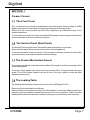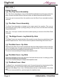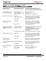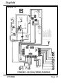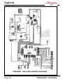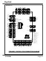
1
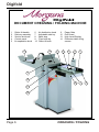
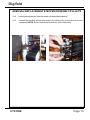
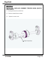
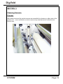
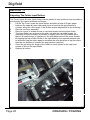
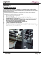
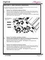
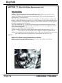
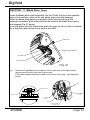
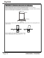
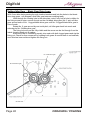
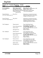
DOCUMENT
CREASING / FOLDING MACHINE
SERVICE MANUAL
Morgana Systems Limited Snowdon Drive Winterhill
Milton Keynes Buckinghamshire MK6 1AP United Kingdom
Telephone: ( 01908 ) 608888 Facsimile: ( 01908 ) 692399
ISSUE 4
SEPTEMBER 2003
120-102
INTRODUCTION
MORGANA DIGIFOLD
i ..........Introduction
The purpose of this manual is to explain the procedure for dismantling and re-assembly of the major assemblies on the Morgana
Digifold machine.
All the engineering adjustments are shown at the end of each
relevant section.
Operator's adjustments and routine maintenance are explained in
the appropriate operators manual which should always be used in
conjunction with this manual.
It is always a good idea to have a copy of the machines illustrated
parts manual available when servicing, as its illustrations provide an
invaluable reference to the construction of the individual assemblies
used to build the machine.
ii .........Fasteners
All threaded fasteners are isometric & all nuts are isometric hexagon.
All screws are hardened high tensile steel.
Cap head, Button head, Socket countersunk, Shoulder bolts and
Grubscrews have internal hexagon drives which require isometric
hexagon wrenches (allen keys). Ball drivers may be used, but care
should be takenparticularly when releasing screws for dismantlingto
avoid breaking the driver as they cannot cope with full tightening
torques.
NOTE.........Do not substitute fasteners with low grade alternatives
which may fail or become irremovable.
Page 2
CREASING / FOLDING
Digifold
Pan head and Cross-head countersunk screws all have metric Taptite threads and
Pozi-drive recesses. Use No.2 point Pozidriv or Supadriv drivers for all screws M4 &
above, and No.1 point drivers for M3 & below.
WARNING
WORK SHOULD BE CARRIED OUT BY A TRAINED AND COMPETENT
E N G I N E E R
A N D
A L L
S A F E T Y
PROCEDURES SHOULD BE ADHERED TO.
SWITH OFF MAINS POWER BEFORE COMMENCING
DO NOT USE PHILLIPS DRIVERS - THESE WILL DAMAGE
T H E S C R E W S & M AY S L I P, C A U S I N G D A M A G E O R
Warning
This machine is heavy care should be taken
when handling
iii ........Identification
For general identification of areas of the machines, the following
terms are used:Operator side (control consul facing)
Rear of machine (opposite to control consul)
Delivery end (to the left of the operator side)
Feeder end ( on your right )
iv ........New Machine Preparation
Remove all packaging materials
All metal parts, including the folding rollers have a protective coating
And any excess should be removed.
Connect the power cable to the mains supply. The machine
requires 230V 50Hz 10 Amps or 115 60Hz 15 Amps.
Fit the delivery to the machine supporting it with the hoop.
Turn the fold rollers by hand to ensure they rotate freely.
Switch on the machine and check that all functions operate.
Set up the machine to fold paper and check that the machine feeds
and folds correctly.
SYSTEM
Page 3
INDEX
Introduction………………………………………………………………………..PAGE
¡
Introduction
¡¡
Fasteners
¡¡¡
Identification
iv
New Machine Preparation
Section 1…… Covers………….…....................................................................
Creaser Covers............................................................. 7
Folder Covers................................................................ 8
Section 2…… Vacuum Valve…………………………………………………….
Valve Plunger Replacements...........................................9
Valve Coil.........................................................................9
Section 3…….Vacuum Drum ...........................................................................
Belt Removal/Replacement...........................................10
Section 4 ……Main Mechanism - Creaser Unit................................................
Removal of Unit...............................................................11/12
Removal /Replacement Stepper Drive Belt / Pulleys......13
Section 5…….Infeed Roller Removal/Replacement - Creaser……………………...14
Section 6…….Drive Hub - Replace Rubber Torsion Bush (shock absorber)..........15
Section 7…….Drive Link Refurbishment…….…………………………………...........16
.
Section 8…….Electrics………..………….…………………………….......……...
Removal/Refitting Control PCB’S................................17
Removal/Replacement Stepper Drive Box ..................17
Removal/Replacement Runtime PCB........ ..................18
Removal/Replacement Stepper Drive Plate PCB.........18
Zero Total Count........................................ ..................18
Section 9…..Optical Sensors…….…………………………………………................
..................... ........................Cleaning Sensors - Creaser.......................................19
..... ................ ........................Changing Sensors - Folder Unit Leading Edge..........20
..... ................ ........................Changing Sensors - Folder Unit Clip 1.......................21
.... ................. ........................Changing Sensors - Folder Unit Clip 2.......................21
Page 4
CREASING / FOLDING
Digifold
Section 10…...Removing / Replacing Fold Blade Assembly……………….……
..................... ........................Top Blade....................................................................22
..................... ........................Bottom Blade...............................................................22
..................... ........................Setting Blade Control.................................................23/26
..................... ........................Adjusting Blade Drive Motor Overtravel......................26
..................... ........................Adjusting Top Door Safety Switch...............................27
Section 11…..Fold Rollers…….…………………………………………................
..................... ........................Adjusting the Folder Input Rollers...............................28
..................... ........................Adjusting the Folder Exit Rollers.................................29
..................... ........................Main Fold Rollers - Removal.......................................30
..................... ........................Main Fold Rollers - Replacement ...............................31
..................... ........................Main Fold Rollers - Roller Gap Setting........................32
..................... ........................Blade Drive Shaft Assy................................................33
Section 12…..Calibration…….…………………………………………................
..................... ........................Machine Set-up Prior to Calibration............................34
..... ................ ........................Calibration.................................................................35/36
..... ................ ........................Metric to Inch..............................................................36
..... ................ ........................Returning Creaser Blade Home After Crunch.............37
.... ................. ........................Sensor Calibration / Alignment ................................ 38
..... ................ ........................Setting Blade Gear Drive Lugs...................................40
..... ................ ........................Blade Deflection Diagram...........................................41
Section 13…...Trouble Shooting…………………………………………………
.............................................Creasing Unit.............................................................42
.............................................Folder.... Unit............................................................43/44
Section 14…….Circuit Diagrams………..………….…………………………….......…
.............................................Creaser - UK - Wiring Diagram.................................45
.............................................Creaser - USA - Wiring Diagram...............................46
.............................................Creaser Control PCB Connection Diagram................47
............................................ Control PCB / Display Connection Diagram...............48
.............................................Stepper Box Wiring Diagram.......................................49
.............................................Stepper Box Connection Diagram...............................50
.............................................DigiFold Wiring Diagram..............................................51
.............................................Runtime PCB Connection Diagram.............................52
.............................................Digidriver Plate Connetion Diagram............................53
SYSTEM
Page 5
Digifold
DOCUMENT CREASING / FOLDING MACHINE
1
2
3
4
5
Roller tilt handle
Delivery assembly
Suction slot knob
Control panel
Air separation knob
2
6
7
8
9
10
Air distribution knob
Adjustable side lay
Back stop
Fixed side lay
Roller tilt knob
12
11
12
13
14
11
Paper Gate
Exit Guard
High Level Display
Extension table fixing
screws
8
6
13
9
14
7
1
10
5
3
4
Page 6
CREASING / FOLDING
Digifold
SECTION 1
Creaser Covers:
1.1 The Front Cover
The compressor cover which is situated below the control panel. Its secured by 16 off M4
taptite screws and is located by three tongues protruding into the main frame.
Removal of this cover provides access to the compressor, the Black Box assy. & the
crease mechanism.
To remove this cover, remove all screws and twist forwards to clear emergency stop button
and mains socket, pull out to release the tongues.
1.2 The Service Panel (Rear Panel)
The Service Panel is at the rear of the machine and is secured by four screws.
Removal of this panel allows access to the suction valves & pipework.
To remove this panel loosen all screws, lift up the panel and twist outward to unhook the
keyhole locations on the opposite side to the screw fittings.
1.3 The Creaser Mechanism Covers
The creaser mechanism is situated in the middle of the machine and is covered by a fixed
and a hinged guard.
To remove these guards just remove the four screws (M4 x 8 long) beneath the entry
guard. Pull off the rubber handle from the tilt lever, the entry guard can now be lifted
upwards and removed.
1.4 The Loading Table.
The Loading table doubles up as a cover for the Control & Display P.C.B’s.
Removal of the loading table is as follows:Remove all eleven countersunk screws from the feed bed. Loosen the side layscrews and
bring the side lay assembly towards the operator side of the machine. Then lift out the
loading table towards the rear of the machine, passing over the fixed lay of the feed bed.
SYSTEM
Page 7
Digifold
SECTION 1
Folder Covers
1.5 The Top Cover Assembly
The Top Cover Assembly is on top of the Fold Roller Mechanism and hinges upwards to
allow access to the Main Rollers, the Input Roller, the Blade Assembles & the Sensors.
This cover can be removed from the machine once the Rear Cover assembly has been
removed.
1.6 The Rear Cover Assembly
The Rear Cover Assembly is situated at the output end of the machine. The cover is
secured by two spring clips, by simply pulling on the top of the cover the whole assembly
hinges downwards.
Note: The Conveyor must be removed to enable opening or removal of the Rear Panel
Assembly.
1.7 The Edge Covers - Lay Side & Op. Side
The Edge Covers are a structural part of the machine covers & are secured with pan head
posidrive taptite screws. These covers must be in place to allow fitting of the side covers.
1.8 The Side Cover - Op. Side
Removal of the Side Cover on the operational side of the folder allows access to the drive
motor, the blade motor, the gap set mechanism and timing belts. These covers must also
be removed to allow for setting up of the main rollers.
The cover is secured with pan head posi-drive taptite screws.
1.9 The Side Cover - Lay Side
Removal of the Side Cover on the Lay side of the folder allows access for setting up of the
main rollers & alignment of the sensors.
The cover is secured with pan head posi-drive taptite screws.
1.9 The Base Cover - Rear
The Base Cover is situated at the output end of the machine and is a structural part of the
machine base unit. This cover also supports the delivery assembly when fitted.
Removal of the Base Cover from the folder allows access to the electrics of the folder
unit.
The cover is secured with four pan head posi-drive taptite screws.
Page 8
CREASING / FOLDING
Digifold
SECTION 2
2.1 Valve Plunger Replacement.
!Remove coil cable.
!Remove 2 cap head screws, holding body of valve to machine, with 4 mm Allen key.
!Remove valve, be careful not to loosen 0’ ring seal, which has a light coating of
grease to ensure a good seal.
!Remove bottom of valve to release plunger and spring.
Check the rubber valve seating washer is secure and not split and the metal
washer under the nut should be ftted.
5.
Set spool dimension to 44.2 mm. See fig 3. below.
Note: The seating washer is available as a spare Morgana Part No. 04-070 & the
metal washer is also available as a spare Morgana Part No. 481-125.
A damaged washer or incorrect setting of these parts can cause loss of feed, similar
to a faulty electrical component.
6.
Refit in reverse order.
Note:
Do not over tighten aluminum parts and use grease to stop binding.
2.2 Valve Coil.
Resistance readings on the coil should be 10 ohms. To read the volts to the coil, have the
coil connected to the system and read the volts across the coil connections with the feed on.
This should be 12 volts.
SYSTEM
Page 9
Digifold
SECTION 3
SUCTION DRUM AND BELT REMOVAL \REPLACEMENT
3.1 Remove feed bed and side guide.
3.2 Remove valve assembly as in last paragraph.
3.3 Remove ‘0’ ring seal, remove long Allen screw 408-01-050-030.
3.4 Remove choke shaft from none operator side.
3.5 Remove 4 screws securing the bearing center support plate posihead from front of feed frame & 2 cap head, from under the feed frame.
DO NOT adjust or remove red bolt, as this is factory set.
3.6 Remove bearing center support plate 93-010. Be careful when removing
this as two bearings and shims can fall out.
3.7 Remove suction drum and belt, leave in feed drum idler and feed
roller, You can now remove belts.
drum
3.8 Replace in reverse order, again be careful of bearings and shims.
When fitting bearing support, make sure it is up against red bolt.
Page 10
CREASING / FOLDING
Digifold
SECTION 4
MAIN CREASER MECHANISM
REMOVAL OF UNIT:
Tilt the DigiFold assembly by removing the top rear fixing screw and the
top front fixing screw. Also remove the center tilt attachment screw and
loosen the lower fixings. Tilt the unit.
4.1
First access should be gained by removing the top input and output guards
(See Section 1)
4.2
Remove guard micro switch by two screws taking care not to drop them.
4.3
Cut and remove cable ties from cable mounting, retaining wiring loom.
Ensure that the mains is unplugged.
4.4
From the rear of the machine, remove two button socket screws with their
washers.
4.5
Remove the ’unlock’ knob from the front of the machine and unscrew the button
head socket screw located just below this portion. The tilt handle can be
removed by sliding the main mechanism to the rear of the machine.
4.6
Remove the polycord drive belt from the suction drum.
4.7
The unit can be lifted by two people vertically out of the main frame with care.
One person should be guiding the wiring and plugs to ensure they do not get
trapped during the lifting.
SYSTEM
Page 11
Digifold
4.8
Place the unit on a solid and clear bench ensuring no wires are trapped beneath
the metal side plates.
4.9
Assemble loosely around the green drive belt to the pulley
4.10 Replace the unit ensuring the wiring harness is threaded as it was removed
4.11 Attach the belt to the drive shaft.
4.12 Fit the tilt lever to the inside front frame with the bottom button head and screw
in tilt knob.
4.13 Slide rear spacer bar down in position (see below). Fix the bottom screw in and
align the top screw and fit loosely. Replace cable ties to mountings. Align the
roller set square with the fixed lay edge while the front tilt lever is in the centre
position. (Use the rear slots to adjust the square) Tighten the screws and replace
the top covers.
Page 12
CREASING / FOLDING
Digifold
REMOVAL/REPLACEMENT STEPPER DRIVE BELT/PULLEYS
4.14
4.15
Loosen the adjuster nut from the inside unit and slide the belt off.
Loosen the securing socket set screws in the drive pulley on the roller for it to be
remopved (NOTE there is one screw located in a hole in the shaft)
SYSTEM
Page 13
Digifold
SECTION 5
REMOVAL/REPLACEMENT OF INPUT ROLLER
5.1
With the unit on a bench.
5.2 Remove the drive belt and pulley from the roller to be removed.
(See SECTION 4)
WORKING ON THE DRIVE BELT SIDE:
5.3 Remove the three M4 posi-head taptite screws from around the bearing hole
in the side plate (Drive belt side) to allow easy access to the bearing retaining
rings. Remove rings.
5.4 Slide the roller out and remove the bearing from the shaft drive belt side.
The roller can be turned sideways to allow removal.
Note the position of the spring washers.
5.5
Replace the roller in the reverse manner.
Page 14
CREASING / FOLDING
Digifold
SECTION 6
DRIVE HUB:- REPLACE RUBBER TORSION BUSH (SHOCK
ABSORBER).
6.1 Loosen grub screws in one half of hub.
6.2
6.3
Slide hub outward & remove rubber.
Replace in reverse order.
Rubber Torsion Bush
SYSTEM
Page 15
Digifold
SECTION 7
DRIVE LINK REFURBISHMENT
7.1 Remove the drip tray by removing the four securing screws fixed to the tie bars.
7.2 Remove both tie bars and drip tray.
7.3 Remove the micro switch assembly to gain access to the rear drive link.
7.4 Using a short dumpy posi drive screwdriver, unscrew the three screws from the side
of the link plate. Slide the side off (‘O’ Rings should be maintained in position).
The plastic drive link can be removed by sliding it forward.
7.5 Replace the drive link and outer plate.
7.6 Re-assemble in reverse order.
Link Plate
Page 16
Micro Switch Assembly
CREASING / FOLDING
Digifold
SECTION 8 ELECTRICS: REMOVAL/REFITTING PCB’s
BOARD REPLACEMENT - CONTROL P.C.B.
Switch the mains power off.
Remove the feed bed as in paragraph 1.4
Disconnect the mains. Unplug all plugs from the PCB, remove the PCB using a removal
tool to depress the five fixing positions.
BOARD REPLACEMENT - STEPPER DRIVE BOX
Switch the mains power off and remove the front cover and top feed bed.
Cut cable ties and unplug the four green plugs. Remove the two mains plugs.
Follow the power supply lead up and cut through the cable tie fixing it beneath the bed.
Unplug the green plug on the PCB inside the bed.
Unscrew the four fixings attaching the unit to the main frame (support the weight).
Lower the box and remove from the machine.
Unscrew the front fixings, four off screws, (attaching the heat sinks) and turn the unit over.
With the base uppermost remove the four pan head screws at the sides, fixing the base
to the sides of the box, and the six off screws in the base.
Gently lift the base plate off to allow access to the inside, take note of the spade terminals
on each board. (they are the same for each PCB) Remove the terminals.
Lift out the assembly of PCB’s and heat sinks.
REPLACEMENT OF PCB’s - Creaser
First check and set the switches as below:Blade PCB slide switch to read 1 on & 2 on.
Drive PCB slide switch to read 1on & 2 on
Rotary switch set at 1
Rotary switch set at 1
Assemble as a pair with four attaching screws.
Assemble in the reverse order to the above. Slide this assembly into the black box ensuring
the cables are not trapped beneath the heat sinks (the fan wires are black and difficult to
see).
Attach spade terminals in the correct positions and refit base.
NOTE:- See STEPPER BOX WIRING DIAGRAM.
SYSTEM
Page 17
Digifold
SECTION 8 con’t
BOARD REPLACEMENT - RUNTIME P.C.B.
Switch the mains power off.
Remove the rear cover base by unscrewing the 4 off M4 Posi pan head screws.
Unplug all plugs from the PCB.
Remove the PCB from the 4 off pillars using a 2.5 mm allen key.
BOARD REPLACEMENT - STEPPER DRIVE PLATE ASSEMBLY
Switch the mains power off.
Remove the rear cover base by unscrewing the 4 off M4 Posi pan head screws.
Unplug all plugs from the PCB.
Remove the terminals.
Remove the PCB using a removal tool to depress the four fixing positions.
Lift out the assembly of PCB and heat sinks.
Refitting is the reverse of above but care should be taken to ensure that the rotarary switch
and the dip switches are correctly set for the correct PCB, see circuit diagram.
ZERO COUNTER
Set total counter to zero. To do this, the diagnostic plug/socket is situated on the feeder end
beneath the manifold deflection knob.
Switch the machine off at the emergency stop button and insert the calibration plug into the
socket.
Switch on and the display will show the total count in tens. Set this to zero by removing
the calibration plug and the feed to on (down) and the set up switch to zero (up)
The display now shows zero.- Switch the m/c off & to return to normal operating mode
switch the m/c back on.
NOTE This also removes all stored programmes, including Calibration Settings which
must be reinstated.
Page 18
CREASING / FOLDING
Digifold
SECTION 9
Cleaning Sensors
Creaser
With blades removed the optical sensors are accessible for cleaning on either side of the
creaser unit - use a soft brush or cloth to remove any dust that may of collected onto
Sensor lens.
SYSTEM
Page 19
Digifold
SECTION 9
Changing Sensors on the Folder unit
Leading Edge Sensor - Top & Bottom
1.
2.
Remove rear cover, front cover & both top covers.
Tilt the DigiFold assembly by removing the top rear fixing screw and the
top front fixing screw. Also remove the center tilt attachment screw and
loosen the lower fixings. Tilt the unit.
Top Sensor Assembly :1.
2.
3.
4.
Unplug from runtime P.C.B. & remove green plug - feed cable through
apertures.
Remove top input roller by unscrewing the 2 cap head screws at either
end of shaft.
Unscrew the cap head screw from end of sensor unit & remove feeding
cable through hole in side plate.
Replace with new sensor assembly and re-assemle in reverse order.
Bottom Sensor Assembly :1.
3.
4.
5.
Unplug from runtime P.C.B. & remove green plug - feed cable through
apertures.
Unscrew the cap head screw from end of sensor unit & remove feeding
cable through hole in side plate.
Note:- Top input roller need not be removed for fitment but will require
removal for realignment of sensor.
Replace with new sensor assembly and re-assemle in reverse order.
Electrical sensor alignment must be carried out - see section 12, But for
an approximate position the sensors can be aliligned by passing a
3mm diameter drill through the holes in the upper & lower sensor bars.
Page 20
CREASING / FOLDING
Digifold
SECTION 9
Changing Sensors on the Folder unit
Clip Sensors.
Remove front & rear covers.
Note : Unit does not have to be tilted to replace these sensors.
Clip 1 Sensor Assembly :1.
2.
3.
4.
5.
To remove short sensor assembly unplug green plug from runtime
board
Unscrew cap head screw and remove from unit - feeding cable through
hole in side plate.
To remove long sensor assembly unplug green plug from runtime
board.
Remove 2 off nuts & washers securing curved roller guide, and remove
2 off cap head screws at ends of bars. Remove Sensor assembly from
unit - feeding cable through hole in side plate.
Electrical sensor alignment must be carried out - see section 12, But for
an approximate position the sensors can be aligned by passing a 3mm
diameter drill through the holes in the upper & lower sensor bars
Clip 2 Sensor Assembly :1.
2.
3.
4.
5.
To remove short sensor assembly unplug green plug from runtime
board
Unscrew cap head screw and remove from unit - feeding cable through
hole in side plate.
To remove long sensor assembly unplug green plug from runtime
board.
Remove 2 off nuts & washers securing curved roller guide, and remove
2 off cap head screws at ends of bars. Remove Sensor assembly from
unit - feeding cable through hole in side plate.
Electrical sensor alignment must be carried out - see section 12, but for
an approximate position the sensors can be aligned by passing a 3mm
diameter drill through the holes in the upper & lower sensor bars.
SYSTEM
Page 21
Digifold
SECTION 10
REMOVING/ FITTING OF FOLD BLADE ASSEMBLIES
Top Blade
The top blade needs to be in the correct position to enable removal, this is achieved by
passing a 2mm allen key through the top alignment bracket and into the hole in the hub of
the blade drive gear. See diagram below.
Once the blade is correctly aligned it can be levered out using a screwdriver.
Bottom Blade
The bottom blade needs to be in the correct position to enable removal, this is achieved by
passing a 2mm allen key through the bottom alignment bracket and into the hole in the
hub of the blade drive gear. See diagram below
Once the blade is correctly aligned it can be levered out using a screwdriver.
Replacing Fold Blade Assemblies
Replacement is the reverse procedure to the above, the end drive pins in the blade must
be positioned squarely over the lugs in the gears both sides before any pressure is
exerted on the blade to clip it into place.
Using two red handled allen keys (2mm) align the holes in the blade drive gears (black
lugged gears) with the brackets attached to the mechanism side plates, each side.The
gears may be turned by hand. Insert the allen keys to lock the mechanism and align the
blade drive pins both sides with the lugs on the gears, with a small amount of pressure on
the rear face of the blade it will clip into position.
Page 22
CREASING / FOLDING
Digifold
SECTION 10
Setting Blade Central Position
Cen
This adjusts the center position of the knife travel (set with gauge 63.6 mm)
Ensure the Blade setting in Calibration Mode is set to -0.0 as a start position
1.
Using the 2.5mm allen keys provided in the Dispatch Kit, locate one of the
allen keys into the alignment bracket (see FIG. A1) and rotate the Flag Blade Hub
st
(see FIG. A2a) until the allen key is located in the 1 hole in the Blade Drive Ring
(see FIG. A1). The 'lug' on the Blade Drive Ring is now in a central position.
Allen key
Alignment bracket
1st hole
2nd hole
FIG. A1
2.
3.
4.
5.
Loosen the two screws that lock the stop hub onto the blade drive motor shaft (i.e.
the travel stop screw and the small grub screw) see FIG. A2a. The stop hub can now
be rotated freely on the shaft. Rotate the stop hub until the travel stop screw is in line
with the bracket aperture. The stop hub can now be held in the correct position on
the shaft by inserting an allen key through the bracket aperture and into the socket of
the travel stop screw. (See FIG. A2a and FIG. A2b)
Ensure the travel stop screw is positioned 90 degrees to the slot in end of hub.
With the mains power switched on.
Hold the stop hub in the correct position as described above (with the allen key), and
rotate the flag blade hub slowly until the LED marked ‘KNIFE on the Runtime Board
is illuminated.
Lightly tighten the travel stop screw and the small grub screw in the stop hub, and
remove the allen keys.
Note. This gives an approximate start to setting the blade travel.
Increase the gap between the exit Rollers by turning the Fold Gap 2 Adjusting Knob,
until the blade setting jig (Part Number 120-014) can be pushed between the exit
rollers as shown in fig A3
SYSTEM
Page 23
Digifold
SECTION 10
Slot
Flag Blade
Hub
Travel Stop
Screw
Stop Hub
Bracket Aperture
(See FIG. A2b)
FIG. A2a
Bracket Aperture
Allen Key
FIG. A2b
Page 24
CREASING / FOLDING
Digifold
SECTION 10
Top Exit Roller
Blade setting Jig
(120-014)
FIG. A3
6.
7.
Adjust the two over-travel stop brackets to their fully up position (see FIG. A4).
Turn the flag blade hub clockwise, until the top blade (no. 2 ) is felt to touch the
edge of the setting jig.
Note:- If the blade setting jig is not available a straight edge and rule may be used
to measure the distance between the blade edge and th rear of the side plates,
when set correctly the blade should be 63.5 from the rear of the side plates
Over-travel
Stop Bracket
Over-travel
Stop Bracket
Flag Blade
Hub
Travel Stop
Screw
FIG. A4
SYSTEM
Page 25
Digifold
SECTION 10
8.
9.
Holding the Flag blade Hub, gently turn backwards counting 59 steps & hold in this
position, loosen the socket set screw in flag - 2 off and rotate until L.E.D. Marked
knife is illuminated - lock in position
Activate feed switch (with system switch on). Cycle a couple of times, reinsert
setting jig and ensure blade is gently touching jig (measure 63.6) The blade is
now correctly positioned.
Adjusting the drive motor over travel:1.
Ensure the blade setting jig is removed and cycle the blade motor several times,
(using the ‘hAndLE’ mode of operation, see operator manual page 18), until the
travel stop screw is in the position shown in FIG. A5.
2.
Adjust the over-travel stop bracket down to within 0.5 mm of the travel stop screw,
as shown in FIG. A5, and then tighten the fixing screws, do this for both directions
Shown below.
3.
Cycle the blade motor a few times and observe that the travel stop screw is just
clear of both of the over-travel stop brackets when cycling back and forth.
Over-travel
Stop Bracket
Over-travel
Stop Bracket
0.5mm Typ.
Travel Stop
Screw
FIG. A5
Page 26
CREASING / FOLDING
Digifold
Adjusting Top Door safety Switch
1.
2.
3.
4.
Remove conveyor assembly.
Remove front cover
Holding top cover shaft fully into slot adjust until machine switches off when there is
an approximate gap of 6 mm at front end.
Re-tighten screw, replace covers and test.
SYSTEM
Page 27
Digifold
SECTION 11
Adjusting The Folder Input Rollers.
The Folder Upper & Lower Input shafts must be parallel to one another to ensure media is
fed correctly, this can be achieved as follows :1.
Lift the Top Cover, locate the Input Rollers and place a strip of 80 gsm paper
between the upper & lower rollers and check to see that the grip pressure is
constant along the roller length. If the Rollers require adjustment do the following:2.
Remove conveyor assembly.
3.
Remove covers to enable access to cap head screws securing input shafts.
4.
The Input Rollers are secured to the main unit with the cap head screws, by
loosening off these screws it is possible to slightly move the input shafts since
there is a small amount of clearance in the side plates around the screw threads.
By tapping the Input Roller Shafts in the right direction the required pressure can
be achieved (tap the rollers apart to decrease the roller pressure or tap the rollers
towards one another to increase the grip pressure required )
5.
Once the grip along the length of the rollers is equal tighten up the cap head
screws to secure the input shafts.
6.
Replace all covers.
Page 28
CREASING / FOLDING
Digifold
SECTION 11
Adjusting The Exit Roller.
The Exit Drive Roller Assembly is adjustable. The upper drive shaft can be moved to
ensure that the correct drive pressure between the exit roller assembly drive hub and the
nitrile drive hub is achieved.
The pressure between the blade drive ring and the nitrile hub can also be adjusted.
The procedure for making adjustment is as follows:1.
Remove the rear delivery assembly.
2.
Open the Top Cover.
3.
Remove the Rear Cover, Op. Side Cover & Op. Side Edge Cover.
4.
Locate Upper Exit Roller & loosen cap head screw that secures shaft to op. side
of folder unit with a 5 mm allen key.
5.
Using a 10mm A/F spanner turn the shaft to make contact between nitrile drive
wheel and roller drive hub whilst rotating by hand.
Note: check drive is adequate through a complete turn.
6.
Tighten cap head when happy with result.
7.
To adjust nitrile drive wheel to blade drive hub on fold roller drive train,- located
adjacent to the shaft is an adjustable allen screw which can be screwed in using a
2.5mm allen key until resistance is felt.
SYSTEM
Page 29
Digifold
SECTION 11 Main Fold Rollers - Removal
The folding unit has 3 main folding rollers that can be easily removed for replacement, the
Procedure for removing the rollers is as follows:1.
2.
3.
4.
Remove all covers.
Looking at the lay side of the folding unit locate and remove the two torsion springs
on the end’s of the 2nd and 3rd roller assembly’s by releasing the spring hubs.
Making note of which spring goes where as they are handed,
Remove the gap set assembly from the operators side of the machine by releasing
the 3 off button head screws.
Remove the 2 worm gears from the 2nd and 3rd roller assembly’s, one gear has a
spacer behind it these should be kept together for re-assembly.
5.
(i)
(ii)
Remove The 3rd Roller Assembly as follows:Remove 4 off screws (2 off on access housing and 2 off on support housing).
The roller assembly can now be withdrawn from the lay side of the machine.
6.
(i)
(ii)
Remove The 2nd Roller Assembly as follows:Remove 4 off screws (2 off on access housing and 2 off on support housing).
Undo M5 Nut & remove Blade Idler Assembly from each side of machine see
diagram below for location.
(iii)
Remove Exit Drive Roller Assembly this is secured by a M8 cap head screw on th
lay side of the folder unit See diagram on page 29.
Rotate the main roller so that the gear is clear of the exit roller drive ring, the roller
assembly can now be withdrawn from the Op. side of the machine.
(iv)
7.
(i)
(ii)
(Iii)
(Iv)
(v)
(vi)
Remove The 1st Roller Assembly as follows:Remove 4 off screws (2 off on access hosing and 2 off on support housing).
Release tension on the Blade Drive Belt by loosening the 4 off screws on the Blade
Drive Assy. Motor plate.
Remove the pulley from the Blade Drive Shaft assembly.
Remove the 3 off screws, nuts and washers used to capture the blade drive shaft
bearing on the op. Side of the folder unit.
The Blade Drive shaft Assembly can now be removed from the op. Side of the
folder unit.
The roller assembly can now be withdrawn from the lay side of the machine.
Page 30
CREASING / FOLDING
Digifold
SECTION 11 Main Fold Rollers - Replacement.
The main rollers should be fitted into the folding unit in the reverse order of removal.
Procedure for replacing the rollers is as follows:7.
(i)
(Ii)
Replace The 1st Roller Assembly as follows:Insert the roller assembly into the Folder Unit from the lay side of the machine.
Set gear mesh by rotating the op. side hub, there should be no backlash in the
gear train but the feel when fully rotated should not be lumpy.
Replace screws to lock hub in position. See diagram below for an approximate
radial position as a starting point.
Note Radial Position
of Holes & Approx Posn.
of Shaft Flats.
Note Fold Roller 3
Note Fold Roller 2
Note Fold Roller 1
8.
(i)
(Ii)
Replace The 2nd Roller Assembly as follows:Insert the roller assembly into the Folder Unit from the lay side of the machine.
Set gear mesh by rotating the op. side hub, there should be no backlash in the
gear train but the feel when fully rotated should not be lumpy.
Replace screws to lock hub in position. See diagram for an approximate
radial position as a starting point.
9.
(i)
(Ii)
Replace The 3rd Roller Assembly as follows:Insert the roller assembly into the Folder Unit from the lay side of the machine.
Set gear mesh by rotating the op. side hub, there should be no backlash in the
gear train but the feel when fully rotated should not be lumpy.
Replace screws to lock hub in position. See diagram for an approximate
radial position as a starting point.
SYSTEM
Page 31
Digifold
SECTION 11 Main Fold Roller Replacement con’t
Roller Gap Setting.
With the roller gap setting mechanism assembled on its backplate but not fitted to the
machine, adjust both knobs to one end of the total travel.
Turn back, counting five full turns of the potentiometer. (This sets the potentiometer in
approximately a central position)
Ensure the roller gap to be set (starting with roller gap 1, the horizontal pair of large fold
rollers) is adjusted with 80 gsm paper to give a slide fit between the rollers and that the gap
is parallel both ends. Check that the eccentricity of the rollers maintains a constant grip on
the paper throughout its full rotation.
Lock the shafts using jigs see below. Position the gap set mechanism assembly onto the 3
off hexagonal pillars, adjusting the knobs if required to ensure an easy alignment of holes.
Fit the screws and tighten.
Connect the green plugs to the runtime PCB
With the machine switched on and the display showing the roller gap setting, ie RG 1 --.-RG 2 -- -- , loosen the soc set screw in the torsion coupling to allow the potentiometer
shaft to rotate. Adjust the pot until the display reads ‘.10’ carry this procedure out for both
pots, locking the screw to the shaft very gently as this can easily be over
tightened.
Replace The Roller Spring Assemblies as follows:Remove the jigs from the roller shaft ends and assemble the springs with the legs
pretensioned to a parallel position as shown.
Page 32
CREASING / FOLDING
Digifold
SECTION 11 Blade Drive Gears
Insert theBlade drive shaft assembly into the Folder Unit from the operator
side of the machine, slide on the two gears and locate the bearings.
Align the balde drive gears by passing a 2mm allen key through the
alignment brackets, both sides and into the holes in the blade drive gears see diagram Fig A1 below.
Lock the gears onto the blade drive shaft, the gear on the op. side is located
by a dog point allen screw into a hole in the shaft.
Allen key
Alignment bracket
1st hole
2nd hole
FIG. A1
(Iv)
Rotate the Flag Blade Hub and pass a 2.5mm allen key up through bracket
aperture and into allen key hole in grub screw.
Fit the belt between blade drive shaft and the motor drive gear - see diagrams
below:-
Slot
Bracket Aperture
Flag Blade
Hub
Allen Key
Travel Stop
Screw
Stop Hub
Bracket Aperture
(See FIG. A2b)
SYSTEM
Page 33
Digifold
SECTION 12 Machine setup prior to Calibration
Ensure feed system is set up correctly (Papergate gap, Balls & Side Lay etc.)
Set the creaser input rollers square to the rear fixed fence.
Set the top blade square to the rear fixed fence and parallel to the input rollers, ensuring
there is no excess play in the slideways - see sketch below:Side Lay
Paper
0 05mm
0.05mm
Input Rollers
Top Blade
Set the bottom blade relative to top blade to give a good form to the crease profile- see
sketch below:-
Set the digifold rollers parallel to the creaser rollers.
Set the Gap setting of the rollers both to 0.0
0.0
Page 34
CREASING / FOLDING
Digifold
SECTION 12 Calibration Mode.
To switch the machine into calibration mode, do the following:1.
With the machine on insert the calibration plug into the DIN socket located at the
rear of the feed bed.
2.
Hold push button 4 down and press the set-up switch to its down position, the
display will show ‘tabr0’.
3.
By turning the rotary switch you can now scroll through the menu of available
machine settings that can be changed, the order is as follows:Tabr
0
Etch
17
These figures
dEtr
105
are typical values
FECh
35
and can be used
DEtF
90
as an approximate
gAPF
97
start position if no
cEn
-0.0
previous figures are available
EURO - inch
4.
It is possible to toggle between the operator mode and the calibration mode by
holding push button 4 and moving the setup switch between it’s mid position and its
down position.
Prior to calibration the machine must have some pre-defined crease & fold position input
into the program software, do this as follows:Note: Refer to the operator manual for explanation of accessing software menu’s.
Set the crease positions
Etch Adjusts the position of the last crease position relative to the sensor.
Detr Adjusts 1st crease position relative to the sensor.
In operator mode do the following:Use 420mm (A3) long paper (120 gsm wth printed setting marks if available)
Input the following settings:Crease on
Fold off
DELry off
Set display to “set by posn”
F-cLr off
Paper 0 (paper thickness or weight or gloss ie, stiffness)
Crease 1 =50
Crease 2 = 370
place this in store 1
Set 5 crease positions - 94.2, 141.3, 188.4, 235.5, 282.6.- Place in store 2
Run machine using Store 2, at least 10 sheets, shingle and lay leading edge against a
straight edge and check repeatability of creases - the results should be straight lines of
creases.
If first crease is out of position, then it indicates the lead edge sensor is faulty and needs
replacing or resetting using the sensor setup jig.
If the lead crease is straight and the others vary up and down then there could be pitch
errors in the drive train, ie belt braids broken; backlash in main drive gears.
Run machine using Store 1, with one sheet.
Measure lead edge to 1st Crease and lead edge to 2nd Crease and adjust to correct
positions.
SYSTEM
Page 35
Digifold
SECTION 12 Machine Calibration.
Set the 1st knife position (this adjusts first edge sensor on digifold to 1st fold knife)
Fetch = the equivalent to Etch on AutoCreaser, to take up tolerances of roller dia
Deft = this is equivalent to detr on AutoCreaser, adjusts leading edge to first fold.
In operator mode do the following:Using 630mm long paper (80 gsm with printed setting marks if available)
Input the following settings:Crease off
Fold on
DELry off
Set display to “set by posn”
F-cLr off
F1 = 100
F2 = 999.9 place this in store 3
F1 = 500
F2 = 999.9 place this in store 4
Run one sheet using store 3 (catch the sheet at the top exit guide and remove) then run
the same sheet using store 4 (ensure leading edge is same for each) - catch the sheet
at top exit
Measure lead edge to 1st fold and lead edge to 2nd fold and adjust to correct positions.
(Similar to Creaser)
st
nd
Set gap between 1 and 2 fold knives
GapF = Distance between fold knives adjustable - ie.10 = 1.0
Using 630mm long paper (80 gsm with printed setting marks if available)
Input the following settings:Crease off
Fold on
DELry off
Set display to “set by posn”
F-cLr off
F1 = 100
F2 = 500
place this in store 5
Run one sheet using store 5 and measure the 1st fold to 2nd fold distance and adjust to
correct positions.
Cen This adjusts the center position of the knife travel (set with gauge 63.6 mm)
Hold PB4 + set-up switch down
Adjust with knob to cen and adjust with PB1+ knob
EURO - inch
Metric - Imperial settings
Whilst in Engineering mode, scroll to the last position, you can now toggle using
the rotary switch, between mm and inches displayed.
Notes-Setting of lengths round odd figures upwards. ie 0.3 call 0.4
Paper type (Type 0 set to zeros) Type 1= light - Type 2= medium - Type 3=
heavy weight
Note:- all dimensions are relative to the leading edge.
Page 36
CREASING / FOLDING
Digifold
Returning Blade to ’Home’ Position after ’Crunch’
It will be evident that the Blade is stuck in the Top Dead Centre (TDC) if when you press
the PB1 or PB2 Buttons to drive the paper forward or backwards the paper remains
stationary, the Display will also show ‘Crunch’
The procedure for returning the Blade to it’s ‘Home‘ position is as follows:
!Power set to On & System Switch On
!Suction and Feed switches in there Up Position (Off)
!Press Blade Push Button (PB 3), the blade will return to it’s ‘home’ position.
!Remove the paper jam using the PB 1 & PB2 buttons to drive the paper out.
!Clear the Display of ‘Crunch’ by moving the set-up switch to the Zero position.
SYSTEM
Page 37
Digifold
SECTION 12 Sensor Calibration and Alignment.
An electronic kit, (see picture below), has been developed to assist the operation of
'calibrating and aligning the sensors'. This kit can be purchased from Morgana Systems
Ltd, by ordering part number 70-043 (1 off).
Sensor Calibration and Alignment Kit (70-043)
Page 38
CREASING / FOLDING
Digifold
SYSTEM
Page 39
Digifold
Setting Idler Gear - Blade Gear Drive Lugs.
With 2 mm allen key's passing through location brackets and into the holes in the blade
drive ring gears, see diagram, slide idler gear between meshing teeth.
Look through the viewing hole in the side plate, note if only half a hole is visible for
the fixing screw to enter, remove the pin on the exit blade drive gear (No. 2 pin) roll idler
gear around teeth of No. 1 lugged blade drive gear until No. 2 lugged blade drive gear is
free of mesh.
Rotate No. 2 gear around by one tooth pitch, roll idler gear back into mesh and
relocate pin No. 2 blade drive gear.
The fixing hole will now be fully visible and the screw can be fed through from the
inside, loosely attach nut & washer.
Ensure the idler is contacting equally into mesh with both lugged gears and nip the
fixing nut. Check for free movement by rotating both gears & ensure there is no backlash,
once this has been achieved tighten the fixing nut.
No 1 blade drive gear
No 2 blade drive gear
Page 40
CREASING / FOLDING
Digifold
SYSTEM
Page 41
Digifold
Section 13 Trouble Shooting - Creaser
Fault
Reason
Solution
Erratic register of
the creaser
Damaged roller surface
Replace rubber rollers
Red L.E.D. on P.C.B.
Permanently On
Plug PL1
Check plug is connected on board.
Check for loose wires or termination
Faulty Top dual Sensor
On Creaser
Check Sensor Diagnostics, see opposite
Faulty P.C.B.
Vdc +/- 0.5 at R9= 5.0V board side
(Check without paper)
R9=1.2V Plug side
(neg probe pin3 plug 1)
IC8 pin8=5.0V
IC8 pin1=3.4V
Paper jammed
Press Push Button 3 to Ensure Blade is in
’Home’ Position & remove paper.
Also clean lens.
Check continuity of cable
Crunch displayed
when m/c is switched on.
Damaged wires
Yellow L.E.D. on P.C.B.
Permanently On
Plug PL2
Check plug is connected on board.
Check for loose wires or termination
Faulty P.C.B.
Vdc +/- 0.5 at R15= 5.0V board side
(Check without paper)
R15=1.2V Plug side
(neg probe pin3 plug 2)
IC8 pin8=5.0V
IC8 pin7=3.7V
Loose terminals in plugs
Re-crimp or solder terminations
Loose or damaged wires
in sensor housing
Faulty Top dual Sensor
Replace with new unit
No display
Check the fuse on main
P.C.B.
Replace fuse. Check for damage to board.
Continuing blowing of fuse
Check PCB for burning
Replace PCB
Rollers not Rotating
On start-up
PL7
Check plug is connected on board.
Check for loose wires or termination
Feeds O.K. & Counts O.K. PL5
But Does Not Crease.
Note-Suction pulse length
PL5
Check plug is connected on board.
Check for loose wires or termination
Intermittent fault on crunch
or paper edge sensor
Page 42
Check Sensor Diagnostics, see opposite
CREASING / FOLDING
Digifold
Section 13 Trouble Shooting - Folder
Fault
Erratic register of
the fold relative to
the crease.
Reason
Fold in Wrong Position
Roller Gap too wide
Damaged roller surface
Blade Drive Mech Sticking
Stepper PCB switch
setting wrong
Solution
Micro Adjust F1 or F2
Adjust/ Check Potentiometers is OK.
Replace rubber rollers
Blades tight in delrin guides
Check circuit diagrams
Red L.E.D Knife,
Plug CN12
on P.C.B. Permanently Off
Check plug is connected on board.
Check for loose wires or termination
Change Slot Detector Sensor
Red L.E.D Knife,
Plug CN12
on P.C.B. Permanently On
Check plug is connected on board.
Check for loose wires or termination
Change Slot Detector Sensor
Check Flag Screws are secure.
Clip P displayed
Press Push Button2 and
remove paper from Infeed.
Use Calibration unit pt no.70-043
to check sensor alignment
Adj. VR on PCB anti clock, increase
beam intensity
Replace Sensor
Paper jammed
Sensor Alignment fault
Faulty Sensor
Damaged wires
Clip 1 displayed
Paper jammed
Sensor Alignment fault
Faulty Sensor
Damaged wires
Clip 2 displayed
Paper jammed
Sensor Alignment fault
Faulty Sensor
Damaged wires
SYSTEM
Press Push Button1 and
remove paper from Delivery .
Use Calibration unit pt no.70-043
to check sensor alignment
Adj. VR on PCB anti clock, increase
beam intensity
Replace Sensor
Press Push Button1 or 2 and
remove paper from top shute.
Use Calibration unit pt no.70-043
to check sensor alignment
Adj. VR on PCB anti clock, increase
beam intensity
Replace Sensor
Page 43
Digifold
Section 13 Trouble Shooting - Folder
Fault
Reason
Solution
Display On but No
Drive to Rollers
System Switch will not
Hold in when Actuated
Check that all Guards are Closed
Check Gaurd Microswitches operating
Check magnetic reed switch functions ok
Continual blowing of
fuse on stepper plate
Faulty transformer
Check PCBs for burning
Faulty RF Filter
Replace Transformer/s
Replace PCB
Check the RF Filter/Replace
Knife Motor not running
Plug CN1
Faulty Transformer
Check plug is connected on board.
Check for loose wires or termination
Check Transformer Voltage 28 VAC
Change stepper PCB
Faulty PCB
Rollers not Rotating
On start-up
Plug CN2
Faulty PCB
Check plug is connected on board.
Check for loose wires or termination
Check Transformer Voltage 56 VAC
Change stepper PCB
Rollers Rotating slow
On start-up and Display
Shows F------0
Lead Edge Sensor
Wrongly adjusted
Check Slider Sw1 on Runtime board is
set to Right Hand side.
Check potentiometers Rv1 & Rv2 are
correctly adjusted use Calibration
Unit 70-043
Lead Edge Sensor Faulty Check using Calibration Unit 70-043
Delivery Belt not driving
Plug CN4
Faulty PCB
Delivery Roller
incorrect Position
Plug Cn5
Check plug is connected on board.
Check for loose wires or termination
Check Transformer Voltage 28 VAC
Change stepper PCB
Check for loose wires or termination
Adjust/ Check Potentiometer is OK.
Delivery Roller not driving Stepper PCB red/grn
to position
Faulty PCB
Check plug is connected on board.
Check Transformer Voltage 28 VAC
Change stepper PCB
Stepper PCB red/grn
LED not on.
Check 240 v supply
Check and replace if required
Change stepper PCB
Page 44
Faulty Power Supply
Faulty Wiring
Faulty PCB
CREASING / FOLDING
HOME
SWITCH
BL
HOME SWITCH
75-111
FEED
75-100
SET
BL
BUTTON 1 BUTTON 2
76-229
76-228
DUAL
SENSOR
JAM
76-230
BL
BRN
EDGE
DETECT
BLADE POSITION
SENSOR 76-233
BRN
BLK
75-095
GUARD
SWITCH
BLK
26
75-098
75-101
ADJUST
valve
coil
GUARD SWITCH LEAD
75-102
12
8
6
SUCTION
13
11
9
7
2
DRIVE
STEPPER
VALVE
JAM RX
JAM TX
EDGE RX
EDGE TX
ENCODER
CRANK
ROTN.
BLADE
HOME
16
17
SET
BLADE
STEPPER 1
4
5
18
ADJ
19
SUCTION
20
21
BUTTONS
3
4
MAIN PCB PL8 TO
DISPLAY PCB PL1
DISPLAY LINK CABLE
PAPER
THICKNESS
PAPER
LENGTH
ENGINEERING
SERIAL
BLADE
STEPPER 2
MAIN PCB
BUTTON 3 BUTTON 4
14
15
FEED
PIN 4&5 DIGIFOLD
GUARD
PIN 3&4 A/CREASER
SYSTEM SWITCH COIL
PSU
3
1
BUTTONS
1
2
VALVE LEAD
75-108
75-099
STACKER
GUARD
SWITCH 75-040
75-094
BRN
75-096
MAIN PCB PL9 TO
RUNTIME PCB PL1
75-097
22
23
24
25
75-128
DIAGNOSTIC LEAD
BL
BL
BRN
28
L
BRN
29
1 TO 25
26
27
28
29
30
31
33
37
38
39
40
41
42
43 TO 57
58
59
31
BL
N
BL
BRN
ylw/grn
COMP
ylw/grn
40
L
BRN
ylw/grn
38
EARTH LEAD
76-235
58
DRIVE
E
L
DRIVE MOTOR
76-129
41
ANTISTATIC
UNIT
DISTRIBUTION
BLOCK
SIGNLE EARTH
BONDING POINT
M
N
GREEN
EMERGENCY STOP
INPUT LEAD 75-122
E
STEPPER BOX MAINS LEAD
75-116
37
33
SEE COLOUR CODE SHEET DRAWING NUMBER (70-025)
STACKER GRD SWITCH (75-040/3)
COMP SWITCH NEUTRAL (75-126)
COMP SWITCH LIVE (75-125)
COMPRESSOR LEAD (75-124)
SYSTEM SWITCH O/PUT LEAD (75-120)
SYSTEM SWITCH INPUT LEAD (75-119)
EMERGENCY STOP INPUT LEAD (75-122)
PSU INPUT LEAD (75-115)
EARTH. CHASIS TO CON BLOCK (75-121)
EARTH. CHASIS TO CREASING UNIT (76-232)
STEPPER BOX POWER LEAD (75-116)
DRIVE MOTOR (SEE DRAWING NUMBER (76-129)
BLADE MOTOR (SEE DRAWING NUMBER (76-234)
SEE STEPPER BOX WIRING DIAGRAM 124-002
DRIVE MOTOR EARTH LEAD (76-235)
BLADE MOTOR EARTH LEAD (76-236)
DRIVE SIGNAL LEAD 75-145
M
E
SIGNLE EARTH
BONDING POINT
SYSTEM SWITCH OUT PUT LEAD
75-120
30
COMP. LEAD
75-124
SYSTEM
SWITCH
PSU OUT PUT LEAD 125-08-11
COMP.
SWITCH
27
N
BL
L
BLADE SIGNAL LEAD 75-146
BRN
N
BRN
SYSTEM SWITCH INPUT LEAD
75-119
YLW/GRN
BRN
BL
SYSTEM
N
3
IEC
STEPPER
E
L
AUX. OUTPUT LEAD
75-127
BLADE SIGNAL
DRIVE SIGNAL
IEC
PSU
42
EARTH LEAD
76-236
4
ylw/grn
POWER SUPPLY INPUT LEAD
75-115
L
STEPPER DRIVER AND PSU
SEE DRAWING NUMBER 124-002
FOR CONNECTION DETAILS
N
E
MAINS IN
DRIVE
BLADE
BL
59
M
BLADE
EARTH LEAD
76-232
CREASER UNIT
BLADE MOTOR
76-234
39
Digifold
Section 14
CREASER - UK (50Hz) WIRING DIAGRAM
Page 45
HOME
SWITCH
BL
HOME SWITCH
75-111
BLK
FEED
75-100
SET
BL
BUTTON 1 BUTTON 2
76-229
76-228
DUAL
SENSOR
JAM
76-230
BL
BRN
EDGE
DETECT
BLADE POSITION
SENSOR 76-233
BRN
BLK
75-095
GUARD
SWITCH
75-094
26
75-098
75-101
ADJUST
valve
coil
GUARD SWITCH LEAD
75-102
12
8
6
SUCTION
13
11
9
7
2
JAM RX
JAM TX
EDGE RX
EDGE TX
ENCODER
CRANK
ROTN.
15
16
17
SET
BLADE
STEPPER 1
4
5
18
ADJ
19
SUCTION
20
21
BUTTONS
3
4
MAIN PCB PL8 TO
DISPLAY PCB PL1
DISPLAY LINK CABLE
PAPER
THICKNESS
PAPER
LENGTH
ENGINEERING
SERIAL
BLADE
STEPPER 2
MAIN PCB
BUTTON 3 BUTTON 4
14
FEED
PIN 4&5 DIGIFOLD
GUARD
PIN 3&4 A/CREASER
BLADE
HOME
3
DRIVE
STEPPER
SYSTEM SWITCH COIL
PSU
VALVE
1
BUTTONS
1
2
VALVE LEAD
75-108
75-099
25
22
23
24
BL
BL
75-128
DIAGNOSTIC LEAD
N
27
COMPRESSOR SWITCH LEAD
75-140
BRN
BLACK
L
30
GREEN
29
COMP. LEAD
75-141
COMP.
SWITCH
1 TO 2 5
26
27
28
29
30
31
33
37
38
39
40
41
42
43 TO 57
58
59
BLADE SIGNAL LEAD 75-146
WHITE
N
BL
WHITE
BLACK
BRN
COMP
ylw/grn
EARTH LEAD
76-235
58
STEPPER BOX MAINS LEAD
75-116
38
DRIVE
E
L
DRIVE MOTOR
76-129
41
ANTISTATIC
UNIT
DISTRIBUTION
BLOCK
SIGNLE EARTH
BONDING POINT
M
N
GREEN
EMERGENCY STOP
INPUT LEAD 75-137
E
33
SEE COLOUR CODE SHEET DRAWING NUMBER (70-025)
STACKER GRD SWITCH (75-040/3)
COMP SWITCH NEUTRAL (75-126)
COMP SWITCH LIVE (75-125)
COMPRESSOR LEAD (75-124)
SYSTEM SWITCH O/PUT LEAD (75-120)
SYSTEM SWITCH INPUT LEAD (75-119)
EMERGENCY STOP INPUT LEAD (75-122)
PSU INPUT LEAD (75-115)
EARTH. CHASIS TO CON BLOCK (75-121)
EARTH. CHASIS TO CREASING UNIT (76-232)
STEPPER BOX POWER LEAD (75-116)
DRIVE MOTOR (SEE DRAWING NUMBER 76-129)
BLADE MOTOR (SEE DRAWING NUMBER 76-234)
SEE STEPPER BOX WIRING DIAGRAM 124-002
DRIVE MOTOR EARTH LEAD (76-235)
BLADE MOTOR EARTH LEAD (76-236)
DRIVE SIGNAL LEAD 75-145
M
E
SIGNLE EARTH
BONDING POINT
40
37
ylw/grn
EMERGENCY
STOP
L
BLACK
SYSTEM SWITCH OUT PUT LEAD
75-120
COMPRESSOR SWITCH LEAD
75-139
L
28
SYSTEM
SWITCH
31
SYSTEM SWITCH INPUT LEAD
75-138
BLACK
BRN
PSU OUT PUT LEAD 125-08-11
BLACK
N
YLW/GRN
STACKER
GUARD
SWITCH 75-040
BRN
75-096
MAIN PCB PL9 TO
RUNTIME PCB CN14
75-097
BL
WHITE
WHITE
BRN
Page 46
BLACK
E
N
N
GREEN
3
IE C
STEPPER
E
L
AUX. OUTPUT LEAD
75-127
BLADE SIGNAL
DRIVE SIGNAL
IEC
PSU
42
EARTH LEAD
76-236
4
ylw/grn
POWER SUPPLY INPUT LEAD
75-115
L
STEPPER DRIVER AND PSU
SEE DRAWING NUMBER 124-002
FOR CONNECTION DETAILS
WHITE
MAINS IN
DRIVE
BLADE
WHITE
59
M
BLADE
EARTH LEAD
76-232
CREASER UNIT
BLADE MOTOR
76-234
39
Digifold
Section 14
CREASER - USA (60Hz) WIRING DIAGRAM
CREASING / FOLDING
Digifold
Section 14
GRN
RD
BL
YLW
3
VALVE
GRN
BL
GRN
RD
BL
YLW
BL
RD
1
4
DRIVE
STEPPER
5
BLADE
STEPPER 1
BLADE
STEPPER 2
PSU
2
SERIAL
RD
BRN
BL
BL
BRN
SYSTEM SWITCH
COIL
6
SCRN
ENGINEERING
PIN 3&4 AUTO CREASER
7
25
24
GUARD
RD
YLW
BL
PIN 4&5 DIGIFOLD
BL
BRN
GRN
BL
YLW
RD
GRN
BL
YLW
RD
BL
SHEILD
RD
BL
YLW
GRN
SHEILD
BL
BLADE
HOME
8
CRANK
ROTATION
9
PAPER LENGTH
ENCODER
10
23
PAPER LENGTH
22
EDGE TX
11
EDGE RX
12
JAM TX
75-114
JAM RX
13
BUTTONS
2
1
14
FEED
15
16
SET
17
ADJ
18
SUCTION
19
BUTTONS
3
4
20
1
2
3
4
5
6
7
8
9
10
11
12
13
14
15
16
17
18
19
20
21
22
23
24
25
VALVE (75-108)
PSU OUTPUT LEAD (125-08-11)
DRIVE STEPPER (75-145)
BLADE STEPPER 1 (75-146)
BLADE STEPPER 2
SYSTEM SWITCH COIL (75-102)
GUARD (75-107)
BLADE HOME (75-111)
CRANK ROTATION (76-233)
ENCODER (76-231)
EDGE TX (76-230)
EDGE RX/JAM TX (76-228)
JAM RX (76-229)
BUTTON 1 (75-094)
BUTTON 2 (75-095)
FEED (75-098)
SET (75-100)
ADJ (75-101)
SUCTION (75-099)
BUTTON 3 (75-096)
BUTTON 4 (75-097)
PAPER THICKNESS
PAPER LENGTH
ENGINEERING (75-128)
SERIAL
21
WHT
WHT
ORG
ORG
RD
BLK
BL
BL
PNK
YLW
RD
VIOLET
WHT
ORG
WHT
GRN
GRN
YLW
YLW
CREASER CONTROL PCB CONNECTION DIAGRAM
SYSTEM
Page 47
Digifold
Section 14
DISPLAY PCB
2
14
1
13
PINS 1 & 2 VCC
PINS 13 & 14 GND
75-149
MAIN PCB PL8 TO
DISPLAY PCB PL1
2
14
1
13
CONTROL PCB / DISPLAY PCB CONNECTION DIAGRAM
Page 48
CREASING / FOLDING
54
YLW
V
GRY
OR
RD
BLK
TRANSFORMER
8
7
6
5
3
4
2
1
50
E
E
SW2
N
L
N
L
BLADE
BLADE MOTOR
SEE SHEET 2 FOR CONECTION DETAILS
OF MOTOR & SIGNAL LEADS
4
3
2
1
BLADE SIGNAL
SW2 SET TO POSITION 1
BLADE MOTOR
CONTROL PCB
SW1.1 OFF
SW1.2 ON
SW1
IEC SOCKET
CEE22
FOR PSU
IEC SOCKET
WITH FILTER
FOR STEPPER
BOARDS
YLW/GRN
SYSTEM
42
4
BRN 48
43 BRN
BRN
FUSE
49
FUSE
BL
44
+24V
RD
2
0V
+5V
BL
CN2
GRN
BRN 47
BL
BRN 57
YLW/GRN 45
L
PSU
TERMINAL
BLOCK
2
3
4
41
42
43
44
45
46
47
48
49
50
51
52
54
55
56
57
AC/N
AC/L
CN1
BL
52
BRN
51
YLW/GRN
3
PSU OUTPUT LEAD (125-08-11)
DRIVE SIGNAL LEAD (75-145)
BLADE SIGNAL LEAD (75-146)
DRIVE MOTOR (76-129)
BLADE MOTOR (76-234)
FILTER LIVE TO BARRIER STRIP (125-08-01)
FILTER NEUTRAL TO BARRIER STRIP (125-08-02)
FILTER EARTH TO BARRIER STRIP (125-08-03)
FAN EARTH (125-08-04)
FUSE TO BARRIER STRIP (125-08-05)
CEE22 LIVE TO FUSE (125-08-06)
CEE22 NEUTRAL TO BARRIER STRIP (125-08-07)
CEE22 EARTH TO BARRIER STRIP (125-08-08)
PSU EARTH TO BARRIER STRIP (125-08-09)
PSU INPUT LEAD (125-08-10)
TRANSFORMER (125-10-01)
LONG LEAD TRANSFORMER (125-10-02)
FAN (125-07-01)
FUSE TO BARRIER STRIP (125-08-12)
SEE DRAWING
NUMBER 70-025
MAIN PCB
L
N
N
41
1
2
3
4
DRIVE MOTOR
BL
BRN
SW2
SW2 SET TO POSITION 1
DRIVE SIGNAL
TRANSFORMER
SW1
SW1.1 ON
SW1.2 ON
DRIVE MOTOR
CONTROL PCB
SEE SHEET 2 FOR CONECTION DETAILS
OF MOTOR & SIGNAL LEADS
YLW/GRN 46
DRIVE
BL
1
2
3
4
6
5
8
7
55
BLK
RD
OR
GRY
V
YLW
56
FAN
Digifold
Section 14
STEPPER BOX WIRING DIAGRAM
Page 49
Digifold
Section 14
3.15AMP
F
U
S
E
GREEN
IEC INLET CEE22
PSU SUPPLY
(HOT CONDITION)
4
YELLOW
D.C. OUTPUT
RED
F
U
S
E
BLUE
2.5AMP
IEC INLET
STEPPER
SUPPLY
(COLD CONDITION)
DRIVE
YELLOW + RED/WHITE
RED + YELLOW/WHITE
ORANGE + BLACK/WHITE
41
BLACK + ORANGE/WHITE
BLADE SIGNAL
DRIVE SIGNAL
BLADE
BLACK + ORANGE/WHITE
ORANGE + BLACK/WHITE
42
RED + YELLOW/WHITE
YELLOW
RED
DRIVE SIGNAL LEAD (75-145)
BLADE SIGNAL LEAD (75-146)
DRIVE MOTOR (76-129)
BLADE MOTOR (76-234)
BLUE
3
4
41
42
GREEN
3
YELLOW + RED/WHITE
STEPPER BOX CONNECTION DIAGRAM
Page 50
CREASING / FOLDING
Digifold
Section 14
GAP 1
POT
KNIFE
POSN
GAP 2
POT
BRN
BRN
CN5
4
CN4
3
CN3
2
CN2
1
CN1
CN6
CN7
CN8
CN9
CN10
CN12
CN13
16
CN14
CN17
DIGIFOLD WIRING DIAGRAM
SYSTEM
Page 51
Digifold
GRN
RD
4
BL
YLW
GRN
RD
3
BL
YLW
Edge Rx Edge Tx Sync 1
CN4
CN6
CN5
Stacker Belt &
Roller Motor
Sync 2
CN7
Stacker Gap 1
Roller Posn CN9
CN8
YLW
GRN
BL
RD
BLK
BL
RD
Gap 2
CN10
15
13
BLK
BL
RD
12
BLK
BL
RD
11
10 BLK
RD
BLK
9 RD
8 BLK
RD
7 BLK
RD
5 BLK
RD
6 BLK
RD
Section 14
Rotation
CN11
Knife Posn
CN12
CN3
Stacker Posn Motor
GRN
RD
2
BL
YLW
CN2
Drive Motor
GRN
RD
1
BL
YLW
CN1
Knife Motor
RUNTIME PCB ASSY.
(125-05-01)
CN14
CN13
16
17
1
2
3
4
5
6
7
8
9
10
11
12
13
KNIFE MOTOR SIGNAL LEAD (124-01-07)
DRIVE MOTOR SIGNAL LEAD (124-01-06)
DELIVERY POSN MOTOR SIGNAL LEAD (124-01-20)
DELIVERY DRIVE MOTOR SIGNAL LEAD (124-01-21)
EDGE DETECT RX LEAD(126-060-01)
EDGE DETECT TX LEAD(126-060-02)
SYNC 1 RX LEAD(126-060-04)
SYNC 1 TX LEAD(126-063-02)
SYNC 2 RX LEAD(126-060-03)
SYNC 2 TX LEAD(126-063-01)
DELIVERY ROLLER POSN LEAD (124-01-26)
GAP SET 1 POT LEAD(124-01-01)
GAP SET 2 POT LEAD (124-01-08)
15
16
17
KNIFE POSITION SENSOR LEAD (124-01-02)
SAFETY CIRCUIT LEAD (124-01-10)
INTERFACE CABLE (124-01-09)
RUNTIME PCB CONNECTION DIAGRAM
Page 52
CREASING / FOLDING
Digifold
1
18
19
DELIVERY
DRIVE
MOTOR
KNIFE
MOTOR
1 2 3 4 5 6 78
BRN
YLW
GRY
V
BLK
1 2 3 4 5 6 78
BLK
OR
BLK
OR/WH
BLK
BLK/WH
ORG
YLW/WH
RD
RD/WH
YLW
MAINS
FILTER
BL
TRANSFORMER
BL
YLW/GRN
BRN
BRN
RD
YLW
GRY
V
21
DRIVE
MOTOR
1 2 3 4 5 6 78
RD
BLK
RD
YLW
BL
RD
GRN
DELIVERY
POSITION
MOTOR
2
BRN
20
BLK
BL
YLW/GRN
BLK
3
26
BL
WHI
PNK
VIO
YLW
BL
RD
GRN
BLK
BLK
RD
RD
1 2 3 4 5 6 78
RD
OR
4
YLW
OR
RD
BLK
YLW
BL
RD
GRN
YLW
OR
RD
BLK
YLW
BL
RD
GRN
Section 14
TRANSFORMER
FAN
18
19
20
21
26
DELIVERY DRIVE MOTOR LEAD ( 124-01-24 )
KNIFE MOTOR ( 124-01-05 )
DELIVERY POSN MOTOR LEAD ( 124-01-25 )
DRIVE MOTOR ( 124-01-04 )
DIGIDRIVER MAINS LEAD ( 124-01-30 )
DIGIDRIVER PLATE, CONNECTION DIAGRAM
SYSTEM
Page 53