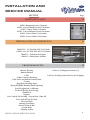
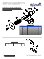
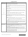
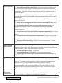
1
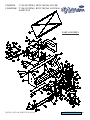
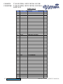
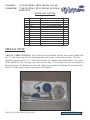
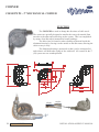
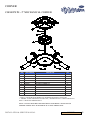
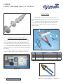
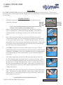
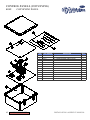
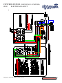
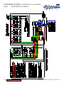
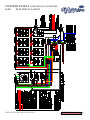
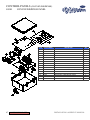
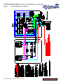
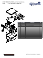
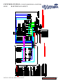
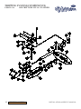
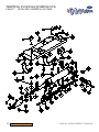
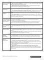
FEEDING SYSTEMS P.O. Box 148, 2397 Hwy 23 Oskaloosa, Iowa 52577-0148 U.S.A. Tel: (641) 673-8451 Fax: (641) 673-7419 U.S. Toll Free: (800) 247-3344 Email: [email protected] INSTALLATION AND SERVICE MANUAL Please visit us at www.cableveyag.com October 2007 Z10741SE INSTALLATION AND SERVICE MANUAL SECTION GENERAL INFORMATION Page 5 Warranty Length, Capabilities and Material Recommendations V-Belt Tension Cable Speed Installation Guide LARGE DRIVE UNIT 13 C50100TM - 2” (50 System) 1 HP w/ METAL COVER C50100TMK - 2” (50 System) 1 HP w/ METAL COVER & LIGHT KIT MOTORIZED HOPPER 18 C50108HWPR - Power Hopper 110 w/ Prox. Recycler C50108HWPRK - Power Hopper 110 w/ Prox. Recycler Klauber C501082HWPR - Power Hopper 220 w/ Prox. Recycler C501082HWPRK - Power Hopper 220 w/ Prox. Recycler Klauber PROXIMITY RECYCLER 22 C50120 - 2” Proximity Recycler Feed Sensor (110 Volt) C50120 220 - 2” Proximity Recycler Feed Sensor (220 Volt) C50120 220 (CANADA) - 2” Proximity Recycler Feed Sensor (220 Volt) INSTALLATION & SERVICE MANUAL 2 INSTALLATION AND SERVICE MANUAL SECTION Page CONTROL HOPPER / AUGER CAP & ASSEMBLY 26 C00161 - Control Hopper / Auger Cap C00155 - Hopper / Auger Cap Assembly CORNERS 31 C50300TWPS - 2” Bi-Directional Mechanical Corner CABLE 33 C38201 - Galvanized Cable w/ 1 1/4” Discs ACCUDIAL FEED DROP 36 C50605PCL - Contact Clear Volumetric Drop C50606PCL - Clear Volumetric Drop 3 INSTALLATION & SERVICE MANAUL INSTALLATION AND SERVICE MANUAL SECTION DISPENSING PANEL Page 38 01580 - Dispensing Panel (1 System) 01581 - Convey/Dispense Panel (3 Systems) 01582 - Convey Panel (2 Systems) 01583 - Convey/Dispense Panel (6 Systems) 01584 - Convey Panel (3-4 Systems) 01588 - Convey Panel (5-8 Systems) TRIPPING SYSTEM (COMPONENTS) 51 C00612-13 - Air Trip Tube MT 3/4 Cylinder C00612-13A - Air Trip Tube MT 3/4 Cylinder C00612-7 - Gestation Air Tripper C00612-5 - Inline Quick Exhaust TROUBLESHOOTING 58 Buttons Wearing Cablevey Feeding System Start Up Buttons Broken Cable Cablevey Feeding System Start Up For Tripping Cable Connector Breaking Cable Jerks and Pulls Extremely Hard Corners Drop Doors Sticking Open Drops/Fill Baffle Bending When Adjusting Feed Clogging Due to Moisture Feed Not Moving Fast Enough Holddowns Hoppers Prox. Switch Not Working - System Won’t Shut Off Prox. Switch Trips Too Fast Recycle Switch Rusting (Feed Tube) Slack in Cable & Disc System Plugs Tripping System INSTALLATION & SERVICE MANUAL 4 HISTORY Intraco, Inc. was founded December 22, 1971 as an import/export company for agricultural equipment. During the early years, Intraco, Inc. began distributing many lines of equipment both in the U.S.A. and many foreign markets. The intense desire to satisfy the needs of the agriculture industry gave Intraco, Inc. a chance to improve a sector of the industry that was lacking efficiency - the feeding system. Intraco, Inc. decided to manufacture and market its own line of feed conveying equipment with the trade name CABLEVEY. The first CABLEVEY system was installed in Ontario, Canada in 1974. Extensive research and marketing of the CABLEVEY feeding system began later that year, involving shipments to Canada, Australia and England. Since that time, thousands of CABLEVEY systems have been manufactured and installed in 47 states and 35 foreign countries. The component parts of the CABLEVEY system, totaling over 470, are manufactured and fabricated by 50 suppliers located throughout the Midwest U.S.A. Over 300 people are involved in the CABLEVEY systems fabricating and marketing chain, including manufacture, assembly, packing, crating, shipping, sales, service, office and administrative personnel. Intraco’s percentage of exports to total sales has grown from 25% in 1974 to 50% at the present time. Intraco, Inc. was presented the President’s “E” Award, a certificate signed in the name of the President of the United States by the Secretary of Commerce, at a special ceremony held in conjunction with a World Livestock & Poultry Seminar in August of 1979. In 1985, Intraco applied it’s knowledge obtained from agriculture conveying and began to develop products for the industrial markets. 1990 was the first installation of the 4” diameter tubular conveyor now being used for a wide variety of materials and installed in various applications. A natural progression was the design of the 2” diameter tubular conveyor system for industrial applications. Representatives of Intraco, Inc. have been involved with trade delegations going to underdeveloped and emerging countries coordinated by the United States Department of Commerce. Intraco, Inc. will continue to be a leader in the industrial and agriculture markets with an aggressive approach to the manufacturing, marketing and distribution of CABLEVEY along with many other products serving the entire world. 5 GENERAL INFORMATION INSTALLATION & SERVICE MANAUL WARRANTY INTRACO, INC. warrants its CABLEVEY Feed Conveying System components, when installed within its recommended limitations, to be free from defects in material and workmanship under normal use and service for which intended, for a period of one year from date of purchase. Any parts, which are proven defective, and the company’s inspection and examination shall disclose to have been thus defective will be replaced or repaired free of charge, f.o.b. Oskaloosa, Iowa. Any defective part must be returned to INTRACO prepaid for examination and inspection. INTRACO’s responsibility covers cost of replacement parts only and does not include repair or replacement caused by misuse, abuse or normal wear and tear. No claim of any kind, whether as to goods delivered or for non-delivery of goods shall be greater in amount than the purchase price of the goods in respect of which such damages are claimed; and failure to give notice of claim within (30) days from date of delivery or the date fixed for delivery, as the case may be, shall constitute a waiver by Buyer of all claims in respect of such goods. The remedy hereby provided shall be the exclusive and sole reedy of the Buyer and any right of the Buyer to consequential and incidental damages is excluded. INTRACO, INC. will use all reasonable means to deliver the property sold hereunder within the terms and the time specified, but will not be liable for any loss, damage, detention or delay caused by accident, strike, walkout, fire, explosion, theft, lightning, windstorm, earthquake, flood, riot, civil commotion, malicious mischief, act of God or any other cause beyond its reasonable control, whether or not the same is herein specified and in any event, INTRACO, INC. SHALL NOT BE LIABLE FOR ANY CONSEQUENTIAL OR INDIRECT DAMAGE ARISING FROM ANY DELAY. This guarantee is made expressly in place of all other guarantees or warranties, expressed or implied, with respect to quality, merchantability of fitness for a particular purpose. INSTALLATION & SERVICE MANUAL GENERAL INFORMATION 6 LENGTH, CAPABILITIES AND MATERIAL RECOMMENDATIONS Maximum recommendations vary with the configuration of the system, cable speed and the material being transported. As noted below, the numbers of corners influences the maximum recommended length of the system. In most cases, the lower the bulk density of the material, the farther it can be moved. Figures are given based on 40 pounds per cubic foot (641 kgs/cu meter) material and cable speed of 82 feet (25m) per minute. No circuit should exceed maximum lengths as show below. All lengths are based on total circuit lengths. We recommend that all applications (excluding poultry) should use the 2” (50) System. All inclines and declines in heights should be 45° or less. 1 1/2” (38) System rated at 20 pounds per minute at 40 pounds per cubic foot. 2” (50) System rated at 35 pounds per minute at 40 pounds per cubic foot. Air Trippers can open maximum 200 Drops. Hand Trippers can open maximum 100 Drops. SYSTEM 1 1/2” (38) System 2” (50) System 7 GROUND (MASH) MAXIMUM PELLETS MAXIMUM Up to 900’ (275m) 4 Corners Up to 900’ (275m) 4 Corners Up to 800’ (245m) 8 Corners Up to 800’ (245m) 8 Corners Up to 600’ (185m) 14 Corners Up to 600’ (185m) 12 Corners Up to 900’ (275m) 4 Corners Up to 900’ (275m) 4 Corners Up to 800’ (245m) 10 Corners Up to 800’ (245m) 8 Corners Up to 500’ (185m) 16 Corners Up to 500’ (185m) 10 Corners Up to 300’ (90m) 18 Corners Up to 300’ (90m) 12 Corners GENERAL INFORMATION INSTALLATION & SERVICE MANAUL LENGTH, CAPABILITIES AND MATERIAL RECOMMENDATIONS MATERIAL RECOMMENDATIONS The CABLEVEY system will handle a variety of materials. Limitations of the system in transporting materials depend upon many factors, such as moisture content, friction qualities and size. Examples of these are cohesive materials such as molasses, large particles such as sow cubes, or high friction materials such as sand. Any material about which there is a question should be sent to us in an adequate amount for testing. MSDS sheets must be provided for materials to be tested. CAPACITIES The capacity of a CABLEVEY system varies with the speed of the cable and the density of the material being transported. Figures given are based on 40 pounds per cubic foot (641 kgs/cu meter) material and cable speed of 82 feet (25m) per minute. 1 1/2” (38) System 2” (50) System 1200 pounds (540kg) per hour 2100 pounds (950kg) per hour With certain materials, it may be necessary to use a lower cable speed to reduce carryover of material past the intended drop. The cable speed is altered by changing ratio of the belt drive on the drive unit. The capacity will vary with type and moisture content of materials being transported. CABLE SPEED MOTOR PULLEY BELT 19.2 01291C (AK27) 01259 (4L280) 21 01292C (AK30) 01259 (4L280) 82 25 01293C (AK34) 01259 (4L280) 88 26.8 01294C (AK39) 01260 (4L290) 101 30.8 01295C (AK44) 01260 (4L290) FT./MIN METER/MIN 63 69 PROPER V-BELT TENSION Push on belt between the sheaves. The force required to deflect the belt 1/8” (3mm) should be between 4 lbs. (1.81 kg.) and 8 lbs. (3.62 kg.). A new belt should be tensioned to require near 8 lbs. (3.62 kg.), force for 1/8” deflection. A 4 lb. (1.81 kg.) force is adequate for a belt that has operated over 50 hours. OVERTENSIONING CAN CAUSE GEAR REDUCER BEARING DAMAGE. INSTALLATION & SERVICE MANUAL GENERAL INFORMATION 8 THE NEW CABLEVEY FEEDING AND CONVEYING SYSTEM CABLEVEY is a registered trademark of a feeding and conveying system produced and marketed by INTRACO, INC. of Oskaloosa, Iowa U.S.A. The NEW CABLEVEY system use a simple principle. Material is moved through a tube with an air craft cable that has plastic discs molded to the cable at regular intervals. The cable moves at high speed in a continuous circuit carrying the material with it at the same speed, this reduces the grinding action and seperation. The flexibility of the cable enables it to be installed in almost any configuration, with the use of corner assemblies having an idler to reduce friction, wear and pull requirements. The material is introduced into the system by means of a hopper which helps keep the material flowing. The cable is pulled through the circuit by a drive unit having an automatic cable tensioning device. The material can be discharged from the circuit at any desired location by placing a hole in the bottom of the tube. Any of a variety of styles of drops can be installed on the tube under the hole -- the style used will depend on the fuction to be performed. The drop styles and functions are described later in this manual. NOTE: All electrical connections are to be made by a qualified electrician, in compliance with all local, state and national codes. DESIGNING and INSTALLING OF A CABLEVEY SYSTEM INSTALLATION AND PREPLANNING: A well-designed and properly installed system will help insure quality and long life of the CABLEVEY feeding system. 1. Conference with customer before installation. Visually inspect the CABLEVEY installa tion site, gathering the following information. a) b) c) d) 9 Identify and obstructions. Check for hanger supports, advise if necessary to recess ceilings. Determine height at which tubing will be installed. Location of bulk bin and/or feed container source or fill auger system. GENERAL INFORMATION INSTALLATION & SERVICE MANAUL e) f) 2. Determine direction of feed flow. Select Drive Unit location -- Preferably install on return line after last drop -- and allow for ad equate support of the Drive Unit. Sketch proposed system. Several rough sketches will help establish the best system layout. If not using fill auger, set the builk tank at different locations and rotate the hopper 90 degrees at each of these loca tions. Keep the incoming feed line angle as gradual as possible ( maximum 45 degrees). The number of corners should be kept to a minimum to increase the cable life. Consider weather protection, serviceability, electrical hookup and recycling of feed in locating the Drive Unit. Place Drive Unit directly after the last drop, if possible. INSTALLATION OF THE SYSTEM: 1. Lay out open tubing end-to-end in aisles or over pens. Locate and punch at desired locations. Note location of holes for AccuDial drops are different than for volumetric drops. Support tube on both ends to prevent burred and jagged edges surrounding the hole from catching cable. File all tubes -- make sure there are no burrs or rough edges. 2. Hang the tubing: a) b) c) d) Locate the cup hooks for attaching the tube hangers -- every 8’ for all systems. Support tubing close to either side of the tube joint and each corner to keep lines leve. Level tubing. Open tube feed lines, from hopper into building 3. Install 90 Degree Corners and Connect System. Place supports close to either side of Corner so Corner does not sag. 4. Large Drive Unit - Installation Instructions: a) b) c) d) e) f) Determine Location: This Drive Unit can be located almost anywhere in the circuit, but if pos sible, it should be located inside the building on the return line of the system. Consider ease of service when locating it, remembering that the cable travels from left to right and the sprocket turns counterclockwise. Install Port: Mount port to outlet on right end of drive frame. Install breather in Gear Reducer by replacing top plug. Mount Drive Unit: Unit can be suspended from chains by using eyebolts attached to mounting angle. Install Motor: Attach motor to motor base and secure pulley to motor shaft. Thread adjusting bolt through motor base and into nut. Attach this assembly to Drive Unit with pivot rod and cotter pins. Install Belt: Align belt by moving motor pulley. Check pulleys, make sure they are tight. Adjust belt tension by moving the adjusting bolt. Install Belt Guard: Position belt guard in place between the guard clip and the drive unit frame. Snap into place, insert two #10 x 3/8” sheet metal screws into belt guard through drive unit frame. INSTALLATION & SERVICE MANUAL GENERAL INFORMATION 10 g) h) i) Electrical Connection: Have qualified electrician wire power supply to drive safety switch and motor. Check direction of motor, sprocket must turn counterclockwise. Attach Cover: Slip cover into place behind spring-covers. Provide good, secure support for unit - either suspended from ceiling or place on floor or drive unit stand. 5. Proximity Recycler Feed Sensor: Never install on return side of drive unit. 6. Installation of Hopper: a) b) c) d) e) 7. Install Cable: a) b) c) d) e) 8. Block Idler Wheel on tension take-up assembly in Large Drive Unit forward a few inches with a short piece of open tube. Feed cable under Idler Wheel and push around system with (01602HW) cable pushing tool. Stay near the front end of cable while pushing, DO NOT force or kink cable. Prestretch cable using (01604HW) cable lock tool. Connect cable, using (C38208) cable connector kit, (01275) cable cutters and instructions on Page 33-35 of Installation and Service Manual. Adjust Cable Tension: After cable has been installed, turn the drive unit by hand with the “V” belt, observing the disc leaving the tube just before it enters the sprocket. This disc should be approximately 1/16” off the tube bottom. If it contacts the tube bottom it can “snap” off the end of the tube, causing wear and excessive drag. If it is too high, feed can accumulate on the tue bottom. If adjustment is required, slightly loosen the bolts holding the mount bracket to the frame, adjust as necessary and retighten. Install Drops: a) 11 Determine the direction in which the feed cable will be traveling. Position hopper so the cable enters the hopper into the recycler unit and exits the hopper through the restrictor port under the motor. Make sure the feed line going through hopper is level and the holddowns are on each side of the hopper. The slide gate under the hopper must be opened to let feed flow out. Open slowly until feed tube is 2/3 to 3/4 full. VERY IMPORTANT: The ports and the trough bottom MUST line up evenly so they will not cause the cable to catch or slip. Run feed in the CABLEVEY system. Watch feed level in the tube and the rotor on the hopper. When the tube come back at 2/3 to 3/4, the recycler switch should shut the hopper off. Mount the drops in proper position over holes. GENERAL INFORMATION INSTALLATION & SERVICE MANAUL 9. Positive Close Installantion a) b) c) d) e) 10. Tripping System Installation: a) b) 11. Attach all drop door wires to the channel. If holes do not line up with wires on doors, move forward (toward tripper) to next closest hole. Attach flared end of channel to narrow end of next piece of channel. If attachment comes up on wire for door, shorten the narrow end of channel enough to get the attachment before the wire on the door. Continue to attach wires from drop doors until line is complete to the end of the row. Spring at end of channel should not have tension on it until drop doors begin to open. After the spring is attached, cut channel at proper length and attach. If drops are more than 4’ apart, install channel support J-Brackets. Mount Air Trip Cylinder in proper location on the open tube. Cylinder must pull on the channel to open drop doors. Tube Mount Tripper will bolt directly to open tube over tube cover. Support frame with “S” hooks & chains. Bolt rod to channel with cylinder rod extended. Hand Trip: Handle to be mounted to the wall and cabled to the channel through pulleys. Connect Power Control Panels are available for most applications. Wiring diagrams are available for systems not using control panels. Have qualified electrician connect power in compliance with all Local, State and National Codes. New CABLEVEY Conveying Panel and Dispensing Panel. 12. Observe System in Operation a) b) c) Operate system to check performance. Introduce feed into system and adjust feed flow to proper level by viewing feed flow through Inspection Section. Set Recycle Unit. 13. Cleanup - Installation crew is to leave installation site free of all boxes, packing materials, etc. brough by the installer. 14. Review CABLEVEY Feeding System operating procedure with the customer of his representative. a) b) c) d) e) f) How to connect the cable. Cable Connector’s position on sprocket. Review maintenance schedule. Adjusting recycle switch. Scan the Installation & Service Manual, identifying sections relevant to customer’s CABLEVEY system. Help the customer complete his CABLEVEY information card to be mailed to the factory. INSTALLATION & SERVICE MANUAL GENERAL INFORMATION 12 C50100TM C50100TMK 2” (50 SYSTEM) 1 HP W/ METAL COVER 2” (50 SYSTEM) 1 HP W/ METAL COVER & LIGHT KIT FUNCTION The Drive Unit is the mechanism which pulls the cable through the system. The cable is pulled through the Drive Unit by a sprocket driven by a 1 HP electric power motor and Gear Reducer. The cable enters the left end of the Drive Unit, travels around the sprocket and is picked up by two Idler Wheels, which guide it to the outlet on the right end of the Drive Unit. The outgoing cable travels under the incoming cable, allowing material INSTALLATION brought into the Drive Unit to drop onto the outgoing cable and be car1. DETERMINE LOCATION: This Drive Unit can be located alried out returning it to the system. most anywhere in the circuit, but if possible, it should be located inside the One of the two Idler building on the return line of the system. Consider ease of service when Wheels is spring-loaded to act as locating it, remembering that the cable travels from left to right and the an automatic tensioning device, sprocket turns counterclockwise. removing slack from the cable. If 2. INSTALL PORT: Mount port (Item 28) to outlet on right end of the slack becomes excessive, or the drive frame. Install breather in Gear Reducer by replacing top plug. if the tension becomes too high, a 3. MOUNT DRIVE UNIT: Unit can be suspended from chains by Drive Unit Safety (Roller) Switch using eyebolts attached to mounting angle (Item 22). will shut off the Drive Unit. 4. INSTALL MOTOR: Attach motor to motor base (Item 19) and secure pulley to motor shaft. Thread adjusting bolt (Item 49) through motor base and into nut (Item 39). Attach this assembly to Drive Unit with pivot rod (Item 20) and cotter pins (included in bag kit). (See figure A) 5. INSTALL BELT: Align belt by moving motor pulley. Check pulleys, make sure they are tight. Adjust belt tension (see page 4 for proper tension) by moving the adjusting bolt (Item 49). 6. INSTALL BELT GUARD: Position belt guard (Item 12) in place between the guard clip (Item 13) and the drive unit frame. Snap into place, insert two #10 x 3/8” sheet metal screws (provided in bag kit) into belt guard through drive unit frame. 7. ELECTRICAL CONNECTION: Have qualified electrician wire power supply to Drive Unit Safety Switch (Roller) (Item 57) and motor. Check direction of motor, sprocket must turn counterclockwise. 8. ATTACH COVER: Slip cover (Item 9) into place behind springcovers (Item 21). 13 DRIVE UNITS INSTALLATION & SERVICE MANUAL C50100TM C50100TMK 2” (50 SYSTEM) 1 HP W/ METAL COVER 2” (50 SYSTEM) 1 HP W/ METAL COVER & LIGHT KIT PART ASSEMBLY INSTALLATION & SERVICE MANUAL DRIVE UNITS 14 C50100TM C50100TMK 2” (50 SYSTEM) 1 HP W/ METAL COVER 2” (50 SYSTEM) 1 HP W/ METAL COVER & LIGHT KIT PARTS LIST ITEM 15 PART NUMBER DESCRIPTION QTY 1 100001P DRIVE FRAME 1 2 100002P CLEANOUT COVER 1 3 100005 WASHER, ADAPTOR 1 4 100006 NUT, ADAPTOR 1 *5 100007 AXLE, IDLER 2 *6 100015 GUIDE RODE 2 *7 100017A IDLER WHEEL 2 8 100019 MOUNTING BLOCK 2 9 100023 CLEAR COVER OR 1 100023MP METAL COVER 1 10 100026 SPROCKET 1 11 100027P MOTOR MOUNT 1 12 100035 BELT GUARD 1 13 100036 GUARD CLIP 1 14 100003 FOAM SEAL 1 15 100004 SPROCKET ADAPTOR 1 16 100050 GEAR REDUCER 1 17 100051P LOWER MOUNT GEARBOX 1 18 100052P UPPER MOUNT GEARBOX 1 19 100021P MOTOR BASE 1 20 100022 PIVOT ROD 1 21 100069 SPRING COVER 2 22 100070 MOUNTING ANGLE 2 23 100108 MOUNT BRACKET TUBE SUPPORT 1 *24 100111P BAFI IDLER BRACKET 1 *25 100112 DRIVE SPRING 2 *26 100113P IDLER / SHUT OFF FRAME 1 *27 100114 DRIVE STOP SLEEVE 1 28 100502P 2” DRIVE PORT 1 29 01001 5/16 FLAT WASHER 12 30 01002 HEX HEAD SCREW 8 31 01003 HEX NUT, YELLOW 8 32 01004 5/16 LOCKWASHER 8 2 33 01006 HEX HEAD SCREW *34 01007 1/2” FLAT WASHER 1 35 01011S 1/4 – 20 HEX NUT S.S. 37 36 01013 3/32 x 1 COTTER KEY 2 37 01018 1/4 LOCKWASHER 25 38 01019 1/2 – 13 HEX NUT 4 39 01020 3/8 – 16 HEX NUT 3 *40 01021 1/2” SAE WASHER 3 41 01023 1/4” SAE WASHER 6 42 01024 1/4 – 20 WING NUT 2 43 01025 SHEAR PIN 1 *44 01026L 1/2 – 13 x 3/4 HEX HEAD SCREW 1 45 01027 1/2 LOCKWASHER 4 46 01028S 1/4 – 20 x 3/4 HEX CAP SCREW S.S. 11 47 01033 3/8 – 16 x 3/4 HEX HEAD SCREW 8 48 01034 3/8 LOCKWASHER 10 DRIVE UNITS INSTALLATION & SERVICE MANUAL C50100TM C50100TMK 2” (50 SYSTEM) 1 HP W/ METAL COVER 2” (50 SYSTEM) 1 HP W/ METAL COVER & LIGHT KIT PARTS LIST CONT’D 49 01035 TENSION BOLT FB-3348 1 50 01037S 1/4 – 20 x 1/2 HEX HEAD SCREW 12 51 01038 LEVELER 1/2 – 13 x 2 1/2 1 52 01039 1/4 – 20 x 1 1/4 CARRIAGE BOLT 1 53 01044 #6 – 32 x 1 1/2 ROUND HEAD SCREW 2 54 01049 #6 – 32 HEX NUT 2 55 01086 3/8 SAE GAUGE WASHER 2 56 01094 #8 LOCKWASHER 6 57 01101R ROLLER SWITCH FOR DRIVE 1 58 01142 2” CONDUIT HANGER 1 59 01112 3/16 SQUARE KEY x 1” 1 60 01297C SHEAVE AK46 – 3/4 1 61 01029 LEG LEVELER SCREW 2 62 100016 BEARING SMALL 4 SPECIAL NOTE ADJUST CABLE TENSION: After cable has been installed, turn the drive unit by hand with the “V” belt, observing the disc leaving the tube just before it enters the sprocket. The disc should be approximately 1/16” off the tube bottom. If it contacts the tube bottom it can “snap” off the end of the tube, causing wear and excessive drag. If it too high, feed can accumulate on the tube bottom. If adjustment is required, slightly loosen the bolts holding the mount bracket (Item 23) to the frame, adjust as necessary and retighten. INSTALLATION & SERVICE MANUAL DRIVE UNITS 16 DRIVE UNIT - TROUBLE SHOOTING 1. UNIT WILL NOT START Check Electrical Supply Reset Drive Unit Roller Switch (Item 57) Check Control Switch Check Motor Reset Check Door Switch 2. UNIT TRIES TO START BUT CAN’T System Overloaded and Tension Incorrect Motor Defective Gear Reducer Defective (Item 16) Reset Drive Unit Roller Switch (Item 57) 3. Control Device Malfunction 5. Check Cable Connector Positioning Sprocket Worn - Flip Sprocket Over or Replace (Item 10) Broken Buttons System Doesn’t Shut Off From Excess Slack Feed Build Up Behind Tensioner 6. MOTOR RUNS, SPROCKET DOES NOT TURN UNIT SHUTS OFF System Overfull Cable Tension Incorrect Foreign Object in Hopper Foreign Object in Corner Foreign Object in Drop Opening Cable Broken UNIT RUNS JERKILY Foreign Object in Corner Obstruction in System Tubing Not Straight Circuit Too Long Misaligned Corner Feed Buildup in Drive Unit Idler (Item 7) in Wrong Bracket (Item 26) Hole. Top Hole for 2” System (1 1/2” Disc) Middle Hole for 2” System ( 1 1/4” Disc) Bottom Hole for 1 1/2” System ( 1” Disc) Check Belt Check Shear Pin (Item 43) Sprocket Loose (Item 10) Gear Reducer Defective (Item 16) 4. CABLE COMES OFF SPROCKET 7. WORN IDLERS Cable Too Short NOTE: Disconnect power before Servicing. Keep cover in place when unit is operating. Keep hands and loose clothing away from moving parts. Be sure belt guard is in place before operating unit. 17 DRIVE UNITS INSTALLATION & SERVICE MANUAL MOTORIZED HOPPERS W/ PROXIMITY RECYCLER FEED SENSOR C50108HWPR - POWER HOPPER 110 W/PROX RECYCLER C50108HWPRK - POWER HOPPER 110 W/PROX RECYCLER KLAUBER C501082HWPR - POWER HOPPER 220 W/PROX RECYCLER C501082HWPRK - POWER HOPPER 220 W/PROX RECYCLER KLAUBER DIRECTION OF CABLE TRAVEL FUNCTION The Motorized Hopper is a metering device and transition for product to flow from the source (Auger) in the the conveying system. Hopper features include slide gate, a paddle rotor, and an observation window. INSTALLATION 1. Determine the direction in which the feed cable will be traveling. 2. Position Motorized Hopper so the cable enters the hopper into the recycler switch and exits the hopper through the restrictor port under the motor (see photo above). Make sure the feed line going through the Motorized Hopper is level and the holddowns are on each side of the hopper. Run feed in the CABLEVEY system. Watch feel level in the tube and the rotor on the Motorized Hopper. When the tube comes back at 2/3 to 3/4 full, the recycler switch should shut the hopper rotor off. If it does not shut off or if it shuts off too soon the sensitivity of the Proximity Recycler may need to be adjusted (see Proximity Recycler for these instructions). INSTALLATION & SERVICE MANUAL MOTORIZED HOPPER 18 MOTORIZED HOPPERS W/ PROXIMITY RECYCLER FEED SENSOR C50108HWPR - POWER HOPPER 110 W/PROX RECYCLER C50108HWPRK - POWER HOPPER 110 W/PROX RECYCLER KLAUBER C501082HWPR - POWER HOPPER 220 W/PROX RECYCLER C501082HWPRK - POWER HOPPER 220 W/PROX RECYCLER KLAUBER PARTS ASSEMBLY 19 MOTORIZED HOPPER INSTALLATION & SERVICE MANUAL MOTORIZED HOPPERS W/ PROXIMITY RECYCLER FEED SENSOR C50108HWPR - POWER HOPPER 110 W/PROX RECYCLER C50108HWPRK - POWER HOPPER 110 W/PROX RECYCLER KLAUBER C501082HWPR - POWER HOPPER 220 W/PROX RECYCLER C501082HWPRK - POWER HOPPER 220 W/PROX RECYCLER KLAUBER PARTS LIST ITEM PART NUMBER DESCRIPTION QTY 1 107382 GASKET 1/16 (.046-.076) 40+DURO 2 2 108014 SPIDER 2X814 1 3 108015 COUPLING BODY 4X182 5/8 BORE 2 4 108016 MALE PLUG 4721 (AVAILABLE SEPERATELY) 1 5 108017 CONNECT FEMALE 4731 (AVAILABLE SEPERATELY) 1 6 108020P PAINTED GRATE 3/4 1 7 108021P PAINTED SLIDE GATE 1 8 108023P PAINTED MOTOR COVER 1 9 108024P PAINTED MOTOR BEARING KIT 1 10 108026 WINDOW 2 11 108027P PAINTED HOPPER FRAME 1 12 108029P 2 IN. TROUGH BOTTOM 1 13 108047 3 SEGMENT ROTOR ASSEMBLY 1 14 108037P PAINTED RUBBER RET STRAP 1 15 108038 RUBBER SEAL FOR HOPPER 1 16 108391 BALL BEARING 5/8 IN. 2 17 108392 BEARING FLANGETTE HW 2 18 108392A FLANGETTE BEARING & BOLT 2 19 108393 BEARING LOCKING COLLAR 5/8 IN. 2 20 800160HWP PAINTED 2 IN. REST PORT 1 21 01001 5/16 FLAT WASHER 2 22 01011S 1/4 – 20 HEX NUT STAINLESS 20 23 01018 1/4 LOCK WASHER 4 24 01023 1/4 SAE WASHER 16 25 01024 1/4 – 20 WING NUT, YELLOW CHROME 8 26 01028S 1/4 – 20 x 3/4 HEX CAP BOLT S.S. 8 27 01041 1/4 – 20 x 1 HEX HEAD BOLT (USE 01028S WITH KLAUBER) 4 28 01083 1/4 – 20 x 3/4 THUMBSCREW BOLT 2 29 01936 5/16 SELF THREADING BOLT 2 30 01937 5/16 WING NUT 2 31 01112 3/16 SQ. KEY x 3⁄4 1 INSTALLATION & SERVICE MANUAL MOTORIZED HOPPER 20 MOTORIZED HOPPERS W/ PROXIMITY RECYCLER FEED SENSOR C50108HWPR - POWER HOPPER 110 W/PROX RECYCLER C50108HWPRK - POWER HOPPER 110 W/PROX RECYCLER KLAUBER C501082HWPR - POWER HOPPER 220 W/PROX RECYCLER C501082HWPRK - POWER HOPPER 220 W/PROX RECYCLER KLAUBER PARTS LIST CONTINUED FROM PREVIOUS PAGE C50108HW 110 VOLT W/PORT ITEM A PART NUMBER DESCRIPTION QTY 108011 1/40 6RPM GEARMOTOR 3M327 OR 1 108011B 7.6 RPM, 1/15 H.P. GEARMOTOR 1 B 01173 CARLON F.S. BOX (E980C) 1 B 01174-1 BLANK COVER F.S. BOX (E980C) 3E 1 D 107501P PAINTED 2 IN. HOPPER PORT 1 C50108HWPR 110 VOLT W/PROX. RECYCLER ITEM *A PART NUMBER DESCRIPTION QTY 108011KL 1/40 6RPM GEARMOTOR 3M327 OR 1 108011B 7.6 RPM, 1/15 H.P. GEARMOTOR 1 B 01173-2 59247 SCEPTER BOX FXC15 PLASTIC BOX 1 B 01174 BLANK COVER F.S. BOX (E980C) 1 C C50120 2 IN. PROXIMITY RECYCLER, 110 VOLT 1 * 108011KL IS OBSOLETE, REPLACE WITH 108011B C501082HW 220 VOLT W/PORT ITEM DESCRIPTION QTY 108012B 220 VOLT GEARMOTOR F/HOPPER W/O RECYCLER 1 108011BB-220 7.6 RPM, 1/15 H.P., 220 VOLT GEARMOTOR 1 B 01173 CARLON F.S. BOX (E980C) 1 B 01174-1 BLANK COVER F.S. BOX (E980C) 3E 1 D 107501P PAINTED 2 IN. HOPPER PORT 1 A PART NUMBER C501082HWPR 220 VOLT W/PROX. RECYCLER ITEM DESCRIPTION QTY 108012B 220 VOLT GEARMOTOR F/HOPPER W/O RECYCLER 1 108011BB-220 7.6 RPM, 1/15 H.P., 220 VOLT GEARMOTOR 1 B 01173-2 59247 SCEPTER BOX FSC15 PLASTIC BOX 1 B 01174 BLANK COVER F.S. BOX (E980C) 1 C C50120-220 2 IN. PROXIMITY RECYCLER, 220 VOLT 1 A PART NUMBER NOTE: The slide gate under the hopper must be opened to let feed flow out. Open slowly until feed tube is 2/3 to 3/4 full. VERY IMPORTANT: The ports and the trough bottom MUST line up evenly so they will not cause the cable to catch or slip. CAUTION: Never operate system with space between discs more than 2/3 to 3/4 full. 21 MOTORIZED HOPPER INSTALLATION & SERVICE MANUAL 2” PROXIMITY RECYCLER FEED SENSOR C50120 - 110 VOLT C50120 220 - 220 VOLT C50120 220 (CANADA) - 220 VOLT LOOKING AT MOTORIZED HOPPER INSTALLATION & SERVICE MANUAL LOOKING AT DRIVE UNIT PROX. RECYCLER 22 2” PROXIMITY RECYCLER FEED SENSOR C50120 - 110 VOLT C50120 220 - 220 VOLT C50120 220 (CANADA) - 220 VOLT To adjust sensitivity on switch use a precision screwdriver to turn screw (between the - and +) slightly to the right of left. 23 PROX. RECYCLER INSTALLATION & SERVICE MANUAL 2” PROXIMITY RECYCLER FEED SENSOR C50120 - 110 VOLT C50120 220 - 220 VOLT C50120 220 (CANADA) - 220 VOLT PARTS ASSEMBLY PARTS LIST ITEM PART NUMBER DESCRIPTION QTY 1 C50204 OPEN TUBE CONNECTOR 6 IN. 1 2 01647 FLATPACK PROX SENSOR 20-250VAC, N.C. 1 3 120003 2” O.D. x 1 3/4” I.D. x 18” POLYCARB TUBE 1 4 C50203 CLOSED TUBE CONNECTOR 1 5 107501P PAINTED 2 IN. HOPPER PORT 1 6 01174 BLANK COVER F.S. BOX (E980C) 1 7 01015 #10-24 HEX NUT 2 8 01650 RELAY 120V 1 POLE NORMALLY OPEN 1 9 01041 1/4 – 20 x 1 HEX HEAD BOLT 2 10 01018 1/4 LOCK WASHER 2 11 01011 1/4 – 20 HEX NUT 4 12 01012 #10 – 24 x 3/4 ROUND HEAD CARRIAGE BOLT 2 13 01173-2 CARLON F.S. BOX (H978E) 1 14 01175 STRAIN RELIEF CONNECTOR (H980E) 15 01141 COPPER 14/4 SJ CORD 16 01197L 11 IN. WIRE TIE 1 17 01925 S.S. HOSE CLAMP, 2 9/16” – 3 1/2” 1 18 01023 1/4 SAE WASHER 2 19 01139 TERMINAL 14RB-8F 2 INSTALLATION & SERVICE MANUAL 2 3 FT. PROX. RECYCLER 24 2” PROXIMITY RECYCLER FEED SENSOR C50120 - 110 VOLT C50120 220 - 220 VOLT C50120 220 (CANADA) - 220 VOLT PARTS ASSEMBLY PARTS LIST ITEM 25 PART NUMBER DESCRIPTION QTY 1 C50204 OPEN TUBE CONNECTOR 6 IN. 1 2 01647 FLATPACK PROX SENSOR 20-250VAC, N.C. 1 3 120003 2” O.D. x 1 3/4” I.D. x 18” POLYCARB TUBE 1 4 C50203 CLOSED TUBE CONNECTOR 1 5 107501P PAINTED 2 IN. HOPPER PORT 1 6 01174 BLANK COVER F.S. BOX (E980C) 1 7 01015 #10-24 HEX NUT 2 8 01649 RELAY 240V 2 POLE NORMALLY OPEN 1 9 01041 1/4 – 20 x 1 HEX HEAD BOLT 2 10 01018 1/4 LOCK WASHER 2 11 01011 1/4 – 20 HEX NUT 4 12 01012 #10 – 24 x 3/4 ROUND HEAD CARRIAGE BOLT 2 13 01173-2 CARLON F.S. BOX (H978E) 1 14 01175 STRAIN RELIEF CONNECTOR (H980E) 15 01172 SDT CONTROL CABLE V144 16 01139 TERMINAL 14RB-8F 2 17 01197L 11 IN. WIRE TIE 1 18 01925 S.S. HOSE CLAMP, 2 9/16” – 3 1/2” 1 19 01023 1/4 SAE WASHER 2 PROX. RECYCLER 2 3 FT. INSTALLATION & SERVICE MANUAL CONTROL HOPPER / AUGER CAP C00161 FUNCTION The Control Hopper/Auger Cap mounts on top of the CABLEVEY Hoppers to receive materials from alternative fill systems. It allows hoppers to be mounted closer to the ceiling and can eliminate the need for hopper extensions in certain applications. The Control Hopper/Auger Cap increases waterproofing benefits. 108396P INSTALLATION & SERVICE MANUAL C00708C HOPPER/AUGER CAP 26 CONTROL HOPPER / AUGER CAP C00161 ITEM PART NUMBER DESCRIPTION QTY 1 108396P COVER PLATE FOR AUGER CAP 2 2 108395P 3” HOLE PLATE FOR AUGER CAP 2 3 01944 PROTECTIVE EDGE TRIM 2 4 108398P HOPPER CAP / PRESSURE SWITCH 1 5 01078L EYEBOLT 1/4 x 20 3” THREAD 2 3/4” 4 6 708008 GASKET, SWITCH 1 7 708003 PADDLE, PRESSURE SWITCH 1 8 01113 1/2” CONNECTOR (RACO #2711) 1 9 708007 STRAP, GASKET 2 10 708001 FRAME, PRESSURE SWITCH 1 11 108405 LOWER COVER PRESSURE SWITCH 1 12 108404 FRAME MOUNT / HOPPER CAP 1 13 01953 5/8 I.D. x 1 1/8 RUBBER GOMMET 1 **14 01952 3-10 SEC. TIME DELAY 110 VOLT 1 **14 01952 220 3-10 SEC. TIME DELAY 220 VOLT 1 15 01138 MICRO SWITCH 1 16 708005 SWITCH MOUNT BRACKET 1 17 01141 14 / 4 SJ CORD 1 18 01113-2 CONNECTOR RSR-1007 1 19 108403 COVER SWITCH / HOPPER CAP 1 20 01414 1/2” ELECT. LOCKNUT 1 21 01954 HOPPER CAP POLY PLUG 1 22 108402P PAINTED HOPPER / AUGER CAP SW 1 23 C00161 1 220 VOLT ELECT. CONTROL BOX 1 ** REPAIR ITEMS ONLY - REPLACED BY ITEM 23 27 HOPPER/AUGER CAP INSTALLATION & SERVICE MANUAL CONTROL HOPPER / AUGER CAP C00161 1 - 220V ELECTRIC CONTROL BOX HOPPER AUGER CONTROL CAP ITEM 23 LABELING CORDS BLACK - 110 VOLT LINE RED - 110 VOLT LINE GREEN - GROUND ITEM PART NUMBER DESCRIPTION QTY 1 01649 RELAY 240V 2 POLE NORMALLY OPEN 1 2 108408 120/240 VOLT 10 SECOND TIMER 1 3 01113 2 CONNECTOR RSR-1007 3 4 01143 COPPER 14/3 SJ CORD 12 FT. 5 01036 #10 – 24 x 1 CARRIAGE BOLT, PLATED 4 6 01015 #10 – 24 HEX NUT 6 7 108407 4 x 4 x 2 PVC JUNCTION BOX 1 INSTALLATION & SERVICE MANUAL HOPPER/AUGER CAP 28 CONTROL HOPPER / AUGER CAP ASSEMBLY C00155 ITEM PART NUMBER DESCRIPTION QTY 1 108396P COVER PLATE 2 2 108395P 3” AUGER PLATE ADAPTOR 2 3 01944 EDGE TRIM 2 4 108394P HOPPER COVER FRAME 1 5 01078 1/4 – 20 x 1 1/2 EYEBOLT 4 The HOPPER/AUGER CAP ASSEMBLY is used as a supplemental component with the Control Hopper Auger Cap. 29 HOPPER/AUGER CAP INSTALLATION & SERVICE MANUAL CONTROL HOPPER / AUGER CAP ASSEMBLY WIRING FOR C00161-220 AUGER WIRING FOR C00161-220 AUGER: BLACK JUMPER TO NORMALLY CLOSED AND TO T1, ON TIME DELAY BLACK WIRE FROM CORD TO COMMON, AND RED FROM CORD TO T2 TIME DELAY, GREEN GROUNDS UNDER SCREW HOLDING SWITCH. SET TIME DEALY SWITCH TO TEN SECONDS. TESTING: BLACK FROM AUGER CAP TO WHITE FROM 220 GRAY CORD. WHITE FROM CAP TO BLACK FROM 220 GRAY CORD, ALSO BLACK FROM MOTOR. LABELING CORDS: BLACK - 110 VOLT LINE RED - 110 VOLT LOAD GREEN - GROUND INSTALLATION & SERVICE MANUAL HOPPER/AUGER CAP 30 CORNER C50300TWPS - 2” MECHANICAL CORNER FUNCTION The CORNERS are used to change the directions of cable travel. The corners are specially designed to transfer the conveyed material from one tube to the other and reduce drag on the system. This is accomplished by means of an idler wheel mounted on bronze bushings. The idler wheel is formed to reduce buildup of material inside the aluminum housing by forcing it to the outside as the idler turns, allowing the cable to carry it away. The aluminum housing is structured so that it can be waterproofed and so that it will hold tubes rigidly in line with itself. All corners for the 2” (50) system are now weatherproofed. tubing 31 CORNER coupler INSTALLATION & SERVICE MANUAL CORNER C50300TWPS - 2” MECHANICAL CORNER ITEM PART NUMBER DESCRIPTION QTY 1** 300005H HARDENED AXLE FOR CORNER IDLER 1 2* ** 300006B BRONZE CORNER BUSHING 2 3* 300384A CORNER IDLER 38 BIDIRECTION W/ HOLE 1 4 300501 1 BOTTOM PLATE 2 IN. CORNER 1 5 300502 1 TOP PLATE 2 IN. CORNER 1 6 300503 1 CLAMP 90 CORNER 2 IN. 2 7 C50211 2 IN. CORNER TUBE 2 8 01011S 1/4 – 20 HEX NUT STAINLESS 10 9 01028S 1/4 – 20 x 3⁄4 HEX CAP BOLT S.S. 10 10 01084 54233-2 SPACER THIN. 2 11 01087 8MM METRIC NUT, PLATED 1 REPLACEMENT PARTS AVAILABLE: * 300385A - CORNER IDLER 38 BIDIRECTION WITH BRONZE BUSHINGS INSTALLED. ** 300005HK - INNER CORNER REPLACEMENT KIT ( 1 HARDENED AXLE & 2 BRONZE BUSHINGS). 300007 - CORNER WEATHERPROOF KIT. NOTE: ALWAYS BE SURE CORNER IS WELL SUPPORTED. NEVER PLACE CORNER VERTICALLY IF MATERIAL IS TO PASS THROUGH IT. INSTALLATION & SERVICE MANUAL CORNER 32 CABLE C38201 - Galvanized Cable w/ 1 1/4” Discs FUNCTION The CABLE is the heart of the CABLEVEY systems. As the cable is pulled through the circuit, it carries conveyed material with it. The cable is an aircraft quality steel cable with specially designed plastic discs spaced at regular intervals. The discs are sized to transfer the highest quantity of material with the least amount of friction. 4 2 INSTALLATION INSTRUCTIONS Mount spool of cable on an axle and thread end over lower idler and out right end port of large drive unit (See Photo A). Push cable from one corner to the next through tube. As soon as the cable has passed a corner fasten the cover in place. When both ends of cable are in drive unit hook 3 or 4 discs of one end in sprocket and pull slack from system by hand, pulling the opposite end. Place discs in sprocket to hold cable in this position. Cut cable using (01275) Cable Cutter and attach connector according to cable connector installation instructions. 3 5 1 C38208 Cable Connector Kit ITEM PART NUMBER DESCRIPTION QTY 1 01105 SNAP RING PLIERS 1 2 01022 SOCKET SET SCREWS 12 3 01104L LONG ALLEN KEY 3 4 C38219 CABLE CONNECTOR TEMPLATE 1 5 209004 SNAP RING CONNECTOR 2 Photo A 01275 Cable Cutter 33 CABLE INSTALLATION & SERVICE MANUAL CABLE CONNECTOR C38209 FUNCTION The CABLE CONNECTOR attaches the two ends of the cable together to complete the loop. The two-piece metal connector is joined together with an internal snap ring, which allows any rotational twist in the cable to be self-correcting. 1. INSTALLATION With cable meshed in sprocket after removing slack, mark discs to be replaced by connector. Remove Remove the right side disc the left side disc NOTE: NINE INCHES BETWEEN THE IDLER SHUT OFF FRAME AND LEFT END OF DRIVE UNIT FRAME (STEP 5) 2. Remove cable from sprocket. Hold disc to be removed with vise grips and cut with hacksaw. Cut TO cable; do not cut cable. Turn cable over and make another cut 180 degrees from last cut. Pull disc halves from cable. 3. Place cable coming from right side of sprocket (with disc removed) in cable connector gauge. Be sure now on gauge is pointing in same direction as cable travel arrow on drive unit. Cut cable with cable cutters 1/16 in. (1.5 mm) off the center of the large slot toward the disc in the gauge. (If the cable is cut directly at the center of the large slot, cable wires may extend beyond the cable sleeve end causing interference) 4. Slide BODY of connector over end of cable (cable cut in step 3). Thread SLEEVE onto cable, turn counterclockwise until end of cable is flush with end of SLEEVE. Slide BODY to outer end of SLEEVE and insert two SET SCREWS. Care must be taken to avoid cross threading. Do not completely tighten set screws yet. 5. Place cable coming from the left side of the sprocket (with disc removed) in cable connector gauge with empty spot over center slot in gauge. Again, be ure arrow on gauge is pointing in same direction as cable travel arrow on the drive unit. Cut cable with cable cutters 1/16 in. (1.5mm) off the center of the large slot toward the disc in the gauge. (If the cable is cut directly at the center of the large slot, cable wires may extend beyond the cable sleeve end causing interference) 6. Slide washer onto cable (cable cut in step 5) with beveled edge toward end of cable. Thread sleeve on cable until flush. Slide washer to end of sleeve and insert set screws. Care must be taken to avoid cross threading. Do not com pltely tighten set screws yet. (CONTINUED ON FOLLOWING PAGE) INSTALLATION & SERVICE MANUAL CABLE 34 CABLE CONNECTOR INSTALLATION (CONTINUED) C38209 7. Fit two ends of connector together and insert snap ring into groove of body. Rotate the snap ring in the groove to be certain that it is seated. NOTE: Snap ring must be inserted with sharp edge out. (Round Side Down) 8. Place connected cable in gauge under slight tension with connector in center slot. If it goes into place easily, connector spacing is correct and the set screws can now be tightened. If connector is not centered on the slot, loosen the four set screws and move the connector. Now, tighten the set screws to 50-60 inch lbs. of torque which is a 15 lb. pull on the end of the 4 in. Long Al len Key (01104L). NOTE: Do not reuse set screws after they have been tightened. Used set screws will not sufficiently clamp to the cable. C38209 Cable Connector ITEM 35 CABLE DESCRIPTION QTY 1 01022 PART NUMBER 1/4 – 28 x 5/32 SOCKET SET SCREW 10 2 209003 CONNECTOR CLAMP SLEEVE 2 3 209381 BODY – 50 CONNECTOR 1 4 209002 CONNECTOR WASHER PLATED 1 5 209004 CONNECTOR SNAP RING 2 INSTALLATION & SERVICE MANUAL ACCUDIAL FEED DROP C50605PCL - CONTACT CLEAR VOLUMETRIC DROP C50606PCL - CLEAR VOLUMETRIC DROP C50605PCL C50606PCL FUNCTION Simply dial in your desired feed setting for each drop in either pounds (lb.) or kilograms (kg.). Markings are visible from either side of the Volumetric Drop. Easy to adjust Closure. Patented Positive Close Feed Dispenser guards against feed spills and insures accurate feedings. INSTALLATION & SERVICE MANUAL ACCUDIAL DROPS 36 2” TEE 8” x 16” 160012SS ITEM STAINLESS STEEL PART NUMBER DESCRIPTION QTY 1 602009 VOLUMETRIC BODY, 1 TO 6 LBS. 1 2 602011 2” SLIDE CLOSURE, 1 TO 6 LB. VOL. DROP 1 3 602012 CLOSER ROD, 1 TO 6 LB. VOL. DROP 1 4 602013 SLIDE STRIP, 1 TO 6 LB. VOL. DROP 1 5 602014 KNOB, 1 TO 6 LB. VOL. DROP 2 6 602010 PIVOT ROD, 1 TO 6 LB. VOL. DROP 1 7 602016 5/16 – 18 NYLON INSERT JAM NUT 1 602017A LONG WIRE DOOR WITH PIVOT HOLES 1 9 01960 5/16 – 18 NYLONG INSERT JAM NUT 1 10 01072 #14 x 1/2 HEX HEAD SHEET METAL SCREW TYB. 2 11 **8 01003 5/16 – 18 HEX NUT, YELLOW CHROME FINISH 1 **12 02086S SS #10 – 24 x 5/8 HEX WASHER HD SCREW 2 *13 105008 HOPPER LOCKING STRAP 1 *14 01966 #10 x 1/4 HWH SCREW PLATED 2 *15 02154 RUBBER O-RING BRAKE SLEEVE 1 *16 C00606R RUBBER TRANSITION 1 *17 02126 #10 x HEX HEAD SHEET METAL SC/ SEAL WASHER 1 *18 02147 RUBBER WASHER, .062 x .120 x .25 I.D. 1 *19 02148S SS #6 x 1/4 HEX WASHER HD SHT METAL SCREW 1 37 ACCUDIAL DROPS * NOT IN B.O.M. ** SHIP 3 PIECES OF (12), 02086S SCREW, WHEN (8), 602017S DOOR IS ORDERED AS A REPAIR PART. USE (18) & (19) TO ATTACH DROP TO AUGER PVC TUBE INSTALLATION & SERVICE MANAUL Control Panel Instructions 1 5 2 3 6 7 4 1. Clock for Conveying 2. Manual Start Switch 3. Manual Stop Switch 4. Green Light 5. Clock for Dispensing 6. Manual Dispensing Switch 7. Manual Cleanout Switch INSTALLATION & SERVICE MANUAL DISPENSING PANEL 38 Photo #1 - Red Light on Drive Unit Photo #2 - Control Drop Photo #3 - Safety Switch (Roller Switch for Drive) Photo #4 - Safety Switch (Roller Switch for Drive) Photo #5 - Air Valve Photo #6 - Manual Bypass Switches 39 DISPENSING PANEL INSTALLATION & SERVICE MANUAL 1. Clock for Conveying (Item 1) A. If the Clock (Item 1) will not start the systems, but the Manual Start Switch (Item 2) will start the systems, the Clock (Part No. 01467TC) will need to be replaced. B. If the systems will not run and the Green Light (Item 4) is off: 1st. Check all Safety Switches (Roller Switches) in Drive Units and reset as necessary. Once the Safety Switches are reset, it will reset the Control Panel and turn the Green Light (Item 4) on. The Red Light on the back of the Drive Unit which needs to be reset will be on (See Photo #1) 2nd. If none of the Safety Switches (Roller Switches) need to be reset, you will need to check the Control Drop (See Photo #2) to be sure the door is completely closed. The system will not run if the door is open. 3rd. If resetting the Drive Units and closing the door on the Control Drop do not resolve the problem, you will need to check electrical power to the Control Panel. 4th. If there is power to the Control Panel, you will need to check the Manual Stop Switch (Item 3). If this is on a qualiÞed electrician will need to open the panel box and place a jumper wire from #4 to #5 on the terminal block at the bottom of the Control Panel (see Wiring Diagram included). If the green light does not come on, there is no power to the Control Panel and you must contact a qualiÞed electrician to restore power to the panel. If the green light comes on, then it is one of the Drive Unit Safety Switches (Roller Switches). The jumper wire must be removed before running the system. The Safety Switch should look like Photo #3. If you can reset the Safety Switch and the system stops again, and it is the same Drive Unit this indicates the cable needs to be shortened. If the Safety Switch looks like Photo #4 it means that the cable needs to be shortened or the system is plugged. To shorten the cable, you will need to remove 3 buttons. See instructions for shortening cable on Page 19 of Installation and Service Manual. 2. Clock for Dispensing (Item 5) A. If the Clock for Dispensing (Item 5)will not dispense feed, but the Manual Switch (Item 6) will, then the Clock (Part No. 01467TC) will need to be replaced. B. If the Manual Switch (Item 6) and the Clock (Item 5) will not open the doors on the drops, you will need to press the small red button on the Air Valve (Photo 5). This should open all the doors. They should stay open as long as the button is depressed and should close when the button is released. If this happens, the air valve is plugged or bad and will need to be cleaned or replaced as necessary (Part No. AS01021K). C. Check the Air Compressor and be sure the water is drained out of it. 3. Manual Bypass Switches A. The switches, located inside the control box, are to be used ONLY if the controller in the panel is not functioning. These manual switches must be turned on and off manually. You MUST turn the switch off if it is ever switched to on. INSTALLATION & SERVICE MANUAL DISPENSING PANEL 40 CONTROL PANELS (DISPENSING) 01580 DISPENSING PANEL ITEM 41 DISPENSING PANEL PART NUMBER DESCRIPTION QTY 1 1635 12 IN. x 12 IN. BOX NM1212B 1 2 1636 CLEAR COVER 12 x 12 NC1212L 1 3 01632 DISPENSING CONTROL PANEL FACE 1 4 01634 11 1/2 x 11 1/2 DISPENSING DECAL 1 5 01638 BACK PLATE JP1212 1 6 01616 1-102.3 SEC INTERVAL SWITCH BI 1 7 01642 TERMINAL BLOCK END 1 8 01641 TERMINAL BLOCK 6 9 01467TC TIME CLOCK 2A519 1 10 01921 MOMENTARY START BUTTON 2X894 1 11 01509 SINGLE POLE 2 WAY SWTICH ON/OFF 1 12 01614 GREEN PILOT LIGHT 1 13 01623S QUICK RELEASE LATCH KIT SSLS (STAINLESS) 2 14 01640 HINGES FOR PANEL BOX 2 15 01618 RH1B-UAC120V 1 16 01619 RH1B-SHIB-05 BASE FOR RELAY 1 17 01615 30 SECOND – 10 SECOND TIMEER TRS51130S1 1 18 AS01021K 110 VAC 3 OR 4 WAY VALVE KIT 1 19 01656 ELECTRICAL SHOCK DECAL 1 INSTALLATION & SERVICE MANUAL CONTROL PANELS (DISPENSING 1 SYSTEM) 01580 ELECTRICAL LAYOUT INSTALLATION & SERVICE MANUAL DISPENSING PANEL 42 CONTROL PANELS (CONVEYING) 01582 CONVEYING PANEL ITEM 43 DISPENSING PANEL PART NUMBER DESCRIPTION QTY 1 01620A 16 x 14 HOFFMAN FIBERGLASS BOX 1 2 01633 13 1/2 x 15 CONVEYING DECAL 1 3 01617 3 – 120 MIN INTERVAL SWITCH QUIS5 1 4 01210 110 VOLT CONTACTOR 2 5 01642 TERMINAL BLOCK END 1 6 01641 TERMINAL BLOCK 7 7 01467TC TIME CLOCK 2A519 1 8 01627 POT. SWTICH 1 9 01627 1 DIAL FOR POT. SWITCH 1 10 01921 MOMENTARY START BUTTON 2X894 1 11 01509 SINGLE POLE 2 WAY SWITCH ON/OFF 1 12 01614 GREEN PILOT LIGHT 1 13 01656 ELECTRICAL SHOCK DECAL 1 INSTALLATION & SERVICE MANUAL CONTROL PANELS (CONVEYING 1-2 SYSTEMS) 01582 ELECTRICAL LAYOUT INSTALLATION & SERVICE MANUAL DISPENSING PANEL 44 CONTROL PANELS (CONVEYING 3-4 SYSTEMS) 01584 45 ELECTRICAL LAYOUT DISPENSING PANEL INSTALLATION & SERVICE MANUAL CONTROL PANELS (CONVEYING 5-8 SYSTEMS) 01588 ELECTRICAL LAYOUT INSTALLATION & SERVICE MANUAL DISPENSING PANEL 46 CONTROL PANELS (CONVEY/DISPENSE) 01581 CONVEY/DISPENSE PANEL ITEM 47 DISPENSING PANEL PART NUMBER DESCRIPTION QTY 1 01620 16 x 14 CARLON BOX NM1614B 1 2 01654 DIN RAIL, DISPENSE / CONVEY PANEL 1 3 02045A SIEMENS LOGO RELAY W/O DISPLAY 1 4 01655 13 1/2 x 15 CONVEYING DECAL 1 5 AS01021K 110 VAC 3/4 WAY AIR VALVE KIT 1 6 01652 SWITCH BRACKET, DISPENSE / CONVEY PANEL 1 7 01210 110 VOLT CONTACTOR 3 8 01642 TERMINAL BLOCK END 1 9 01641 TERMINAL BLOCK 12 10 01467TC TIME CLOCK 2A519 FOR (01467HW) 2 11 01618 RH1B-UAC120V RELAY 3 12 01619 RH1B-SHIB-05 BASE FOR RELAY 3 13 01921 MOMENTARY START BUTTON 2X894 2 14 01509 SINGLE POLE 2 WAY SWITCH ON/OFF 5 15 01614 GREEN PILOT LIGHT 1 16 01656 ELECTRICAL SHOCK DECAL 1 INSTALLATION & SERVICE MANUAL CONTROL PANELS (CONVEY/DISPENSE 3 SYSTEMS) 01581 ELECTRICAL LAYOUT INSTALLATION & SERVICE MANUAL DISPENSING PANEL 48 CONTROL PANELS (CONVEY/DISPENSE) 01583 CONVEY/DISPENSE PANEL ITEM 49 DISPENSING PANEL PART NUMBER DESCRIPTION QTY 1 01620A 16 x 14 HOFFMAN FIBERGLASS BOX 1 2 01654 DIN RAIL, DISPENSE / CONVEY PANEL 1 3 02045A SIEMENS LOGO RELAY W/O DISPLAY 1 4 01655 13 1/2 x 15 CONVEYING DECAL 1 5 AS01021K 110 VAC 3/4 WAY AIR VALVE KIT 1 6 01652 SWITCH BRACKET, DISPENSE / CONVEY PANEL 1 7 01210 110 VOLT CONTACTOR 3 8 01642 TERMINAL BLOCK END 1 9 01641 TERMINAL BLOCK 15 10 01467TC TIME CLOCK 2A519 FOR (01467HW) 2 11 01618 RH1B-UAC120V RELAY 6 12 01619 RH1B-SHIB-05 BASE FOR RELAY 6 13 01921 MOMENTARY START BUTTON 2X894 2 14 01509 SINGLE POLE 2 WAY SWITCH ON/OFF 5 15 01614 GREEN PILOT LIGHT 1 16 01656 ELECTRICAL SHOCK DECAL 1 INSTALLATION & SERVICE MANUAL CONTROL PANELS (CONVEY/DISPENSE 6 SYSTEMS) 01583 ELECTRICAL LAYOUT INSTALLATION & SERVICE MANUAL DISPENSING PANEL 50 TRIPPING SYSTEM (COMPONENTS) C00612-13 AIR TRIP TUBE MT 3/4 CYLINDER 51 TRIPPING SYSTEM INSTALLATION & SERVICE MANUAL TRIPPING SYSTEM (COMPONENTS) C00612-13 AIR TRIP TUBE MT 3/4 CYLINDER PARTS LIST ITEM PART NUMBER DESCRIPTION QTY 1 AS01012 CLEVIS AIR CYLINDER 1 2 AS01059 9” AIR CYLINDER, 3⁄4 1 3 AS01013 PIVOT BRACKET FOR 9” AIR CYLINDER 1 4 AS01945 1/4” PIPE NIPPLE 1 5 AS01041S STAINLESS MUFFLER 1/4” NPT 1 6 AS01038 QUICK EXHAUST VALVE 1 7 AF01036 90 MALE 3/8” (1 / AIR COMPRESSOR) 1 8 AS01046 FLOW REGULATOR 1 9 612034A PAINTED AIR TRIP BRACKET 1 10 612036P POS AIRTRIP LONGWIRE PAINTED FRAME 1 11 600026 SPRING ATTACHMENT CONDUIT CLAMP 2 12 01009 1/4 – 20 x 1 1/4 HEX HEAD SCREW 4 13 01970 9/32 I.D. x 1 O.D. x .125 TK FLATWASHER 4 14 01011 1/4 – 20 HEX NUT 6 15 01028S 1/4 – 20 x 3/4 HEX HEAD CAP SCREW S.S. 2 16 01020 3/8 – 16 HEX NUT 2 17 01137 #8 MED. S HOOK ZINC (79008-35) 2 18 01011S 1/4 – 20 HEX NUT STAINLESS 2 19 01018 1/4 LOCKWASHER 2 20 01028 1/4 – 20 x 3/4 HEX HEAD SCREW 2 21 01018 1/4 LOCKWASHER 2 22 AS01035 1/8” MUFFLER OR 1 AS01066S STAINLESS MUFFLER 1/8 NPT 1 23 AS01050 1/8” TO 1/4” PIPE NIPPLE 1 24 01023 1/4” SAE WASHER 2 25 612037 TRIPPER 3⁄4 CYLINDER GUIDE 1 26 01944 EDGE TRIM 1 27 01033 3/8 – 16 x 3/4 HEX HEAD SCREW 2 28 01034 3/8 LOCKWASHER 2 29 01929MO MESH SLEEVE 2 30 01953 5/8 I.D. x 1 1/8 O.D. RUBBER GROMMET 2 31 02022 1/4 S.S. INTERNAL TOOTH WASHER 1 32 02024 S.S. WASHER 13/64 x 1 x 0.47 1 33 01971 #8 x 1/2 SELF TAPPING SCREW 1 INSTALLATION & SERVICE MANUAL TRIPPING SYSTEM 52 TRIPPING SYSTEM (COMPONENTS) C00612-13A 53 AIR TRIP TUBE MT 3/4 CYLINDER TRIPPING SYSTEM INSTALLATION & SERVICE MANUAL TRIPPING SYSTEM (COMPONENTS) C00612-13A AIR TRIP TUBE MT 3/4 CYLINDER PARTS LIST ITEM PART NUMBER DESCRIPTION QTY 1 AS01012 CLEVIS AIR CYLINDER 1 2 AS01059 9” AIR CYLINDER, 3⁄4 1 3 AS01013 PIVOT BRACKET FOR 9” AIR CYLINDER 1 4 AS01945 1/4” PIPE NIPPLE 1 5 AS01041S STAINLESS MUFFLER 1/4” NPT 1 6 AS01038 QUICK EXHAUST VALVE 1 7 AF01036 90 MALE 3/8” (1 / AIR COMPRESSOR) 1 8 AS01046 FLOW REGULATOR 1 9 612034AP PAINTED AIR TRIP BRACKET 1 10 AS01047 1/8” TO 1/4” PIPE NIPPLE 1 11 02022 1/4 S.S. INTERNAL TOOTH WASHER 1 12 AS01041SK KIT FOR STAINLESS MUFFLER 1/4” NPT 1 13 01970 9/32 I.D. x 1 O.D. x .125 TK FLATWASHER 2 14 01041 1/4 – 20 x 1 HEX HEAD BOLT 2 15 01011S 1/4 – 20 HEX NUT STAINLESS 6 16 01018 1/4 LOCKWASHER 5 17 600026 SPRING ATTACHMENT CONDUIT CLAMP 1 18 600043 4 1/4 U – BOLT TRIPPER CHANNEL 1 19 612054 PLASTIC CHANNEL GUIDE BLOCK 1 20 600044 SUPPORT BRACKET, DROP LEVELING WIRE 1 21 612057 SUPPORT / CYLINDER BRACKET, TRIPPER CHANNEL 1 22 01028S S.S. 1/4 – 20 x 3/4 HEX BOLT 2 23 01037S S.S. 1/4 – 20 x 1/2 HEX BOLT 2 *24 AS01067 CYLINDER 1/8 NPT EXHAUST * NOT IN B.O.M. INSTALLATION & SERVICE MANUAL TRIPPING SYSTEM 54 TRIPPING SYSTEM (COMPONENTS) C00612-7 55 GESTATION TRIPPING SYSTEM TRIPPING SYSTEM INSTALLATION & SERVICE MANUAL TRIPPING SYSTEM (COMPONENTS) C00612-7 GESTATION TRIPPING SYSTEM PARTS LIST ITEM PART NUMBER DESCRIPTION QTY 1 AS01037 ROD CLEVIS, PIN, JAM NUT 1 2 AS01029 AIR CYLINDER 2” BORE 9” STROKE 1 3 AS01036 PIVOT BRACKET AND PIN 1 4 AS01945 1/4” PIPE NIPPLE 2 5 AS01041SK STAINLESS MUFFLER 1/4 NPT 2 6 AS01038 QUICK EXHAUST VALVE 1 7 AF01036 90 MALE 1/4” (1 / AIR COMPRESSOR) 1 8 AS01046 FLOW REGULATOR 1 9 612034A PAINTED AIR TRIP BRACKET 1 10 612036P POS AIRTRIP LONGWIRE PAINTED FRAME 1 11 600026 SPRING ATTACHMENT CONDUIT CLAMP 2 12 01009 1/4 – 20 x 1 1/4 HEX HEAD SCREW 4 13 01970 9/32 I.D. x 1 O.D. x .125 TK FLATWASHER 4 14 01011 1/4 – 20 HEX NUT 6 15 01033 3/8 – 16 x 3/4 HEX HEAD SCREW 2 16 01197L 11” WIRE TIE 1 17 01137 #8 MED. S HOOK ZINC (79008-35) 2 18 01020 3/8 – 16 HEX NUT 2 19 01034 3/8 LOCKWASHER 2 20 01028 1/4 – 20 x 3/4 HEX HEAD SCREW 2 21 01018 1/4 LOCKWASHER 2 *22 600037 5/8” TWO PIECE SHAFT COLLAR TRIPPER CYLINDER 1 23 01929MO MESH SLEEVE 2 24 01953 5/8 I.D. x 1 1/8 O.D. RUBBER GROMMET 2 25 02024 S.S. WASHER 13/64 x 1 x 0.47 2 26 01971 #8 x 1/2 SELF TAPPING SCREW 2 *27 AS01068 CYLINDER 1/4 NPT EXHAUST * NOT IN B.O.M. INSTALLATION & SERVICE MANUAL TRIPPING SYSTEM 56 TRIPPING SYSTEM (COMPONENTS) C00612-5 INLINE QUICK EXHAUST NOTE: WHEN CUSTOMER ORDERS C00612-5 THEY WILL RECEIVE “NEW” PART AS SHOWN AT BOTTOM OF PAGE. “OLD” C00612-5 ITEM PART NUMBER DESCRIPTION QTY 1 AS01041S STAINLESS MUFFLER 1/4” NPT 1 2 AS01038 QUICK EXHAUST VALVE 1 3 AF01039 MALE 3/8” 1 4 AFO1036 90 MALE 3/8” 1 5 01929MO MESH SLEEVE 1 6 02024 S.S. WASHER 13/64 x 1 x .047 1 7 01971 #8 x 1/2 SELF TAPPING SCREW 1 *8 AS01038K DIAPHRAM AND “O” RING KIT 1 * REPLACEMENT KIT “NEW” C00612-5 ITEM 57 PART NUMBER DESCRIPTION 1 AS01070 QUICK EXHAUST VALVE 2 AS01040 1/4 IN. AIR HOSE TRIPPING SYSTEM QTY 1 6 IN. INSTALLATION & SERVICE MANUAL Troubleshooting Problem: Questions to Ask / Solution: Buttons wearing Button wear patterns give clues about system problems: √ Oval shaped buttons - The cable is sliding over the feed and the buttons are pushing up against the inside of the closed tube. Install open tube with holddowns every 4 feet in place of the closed tube. √ Two “V” notches - The cable is being pushed up against the inside of the open tube. Add holddowns every 4 feet. √ A wide “V” notch - Idlers are seized. Check corner idlers for rotation. Clean out foreign material and grease spindle. If idler plugs with feed consistently, replace idler with corner slide (2” system only). √ A narrow “V” notch or several narrow “V” notches - Corners and tubes are sagging causing cable to ride up or down in the corner. Support corners and tubes. √ Cuts into buttons - Old style hopper (C00107) cams worn away completely and metal cutting into buttons. Install new cams. The drop has slipped on the tube letting the metal closer inside of the cleanout slot. √ Buttons tapered after cable connector - This wear occurs each pass over a corner idler wheel if: √ The cable connector spacing is incorrect. Check spacing with gauge. √ System pulls hard with old style corner idlers. Replace idlers with new beveled timednotched idlers. √ Sudden reduction in button size for no apparent reason - Generally starts with a broken button. Feed rolls past the broken button and bunches especially at inclines, thus, pushing the cable against the top of the tube. Also, the cable is forced to ride up inside the corners, which wears on the corner covers and edges of the idler wheels. Buttons Broken √ Are the buttons in the hopper and is it a new installation? The motor is wired backwards. √ Are the corners sagging? Support corners and tube, they must be level. √ Are there foreign objects in the system? Check for foreign objects (rodents, hardware, etc.) in the system. √ Is there excessive feed buildup through small drive unit? Clean out the feed buildup. √ Is there open tube to closed tube with no holddowns at tube connector? Install open tube with holddowns every 4 feet in place of closed tube. Make sure there are holddowns in the system at drive unit, hopper and corner connections. √ Are the tubes in and out of the hopper straight? Realign the tubes in/out of the hopper. √ Are there rough edges on tubing? File off burrs. INSTALLATION & SERVICE MANUAL TROUBLESHOOTING 58 Cable connector breaking √ Did the cable connector break or pull apart? If the set screws are not set deep enough into the cable, they will pull apart. Do not reuse the set screws, snap rings or sleeves when putting on a new connector. New set screws with a deeper hex and a longer allen wrench are now available. Tighten the set screw as deeply as you can (50-60 lb. torque inch) using the longer allen wrench. √ Is the cable connector body touching either side of the drive sprocket teeth? The connector body should be centered between the drive sprocket teeth when passing around the drive sprocket. √ Are cable connectors placed too close together in the system? Cable connectors should be at least 2 feet apart. √ Was the cable connector gauge used when connectors were installed? Always use the gauge to put connector together. √ If it ever breaks, you must change out - sleeve, snap ring and set screws. New improved set screws with a deeper hex and longer allen wrenches are now available. √ Is there too much drag/strain on the system? See “System Plugs” sections for possible causes of drag/strain. √ Are there more corners in the system than the maximum recommendations? Too many corners will cause excessive pull on the system. See Maximum Length Recommendations on Page 4. √ Is the system longer than the maximum recommendations? Systems which are longer than the maximum recommended length create excessive pull on the system. See Maximum Length Recommendations on Page 4. √ What type of feed are they feeding? Pellets put too much of a strain on a 1 1⁄2” system. Consider switching to a 2” system. Cable jerks and pulls extremely hard √ Is the corner idler wheel turning? Check for foreign object in idler wheel and proper direction of rotation of idler wheel. Remove object. Place idler in correctly. Replace idler wheel with corner slide (2” system only) if feed continues to plug in idler. √ Are there rough edges on tubing? File off burrs. √ Is tubing seated properly in the corners? Loosen corner clamp and reseat. √ All reasons given for “System Plugs” can cause the cable to jerk and pull hard. See “System Plugs” section. Corners √ Which corner idler bushing is most likely to wear out first? The corner just before the drive unit. The heaviest loaded corner is the one that the cable passes through just before entering the drive. The lightest loaded corner is the one just after the drive unit. √ Which corner idlers are most likely to plug with feed? The lightest loaded corners (corners just after the drive unit) at the top of inclines. Usually the second corner after the hopper at the top of an incline will plug before any other corner. (This corner idler is lightly loaded and feed naturally falls back into the idler.) Drop doors sticking open √ Are drop doors sticking open and causing feed spills? Pull the trip handle more than once (2 or 3 times) - or - change over to the new positive close system. 59 TROUBLESHOOTING INSTALLATION & SERVICE MANUAL Feed not moving fast enough √ What size system is installed (11⁄2” or 2”)? If a 11⁄2” system, convert to 2” system. Refer to Maximum Length Recommendations on page 4. √ What size motor pulley and belt are being used? Check alternative sizes and cable speeds on Maximum Length Recommendations on page 4. Holddowns √ Are holddowns placed properly throughout the system? Holddowns should be installed every 4 feet/level, every 2 feet/incline and before and after corners, hoppers recyclers and drives. Hoppers √ Are hoppers leaking? Are they hooked up to the double boot extension? If so, replace it with the new 17” Double Boot Ext. Wldm. C38113W or caulk it until it stops leaking. Use silicone sealant on any seams or metal joints. Prox. Switch not working - system won’t shut off √ Is there a control drop? If proximity switch is on the control drop it should shut off immediately. You can adjust the sensitivity. √ Is the proximity switch on an inline switch? The timer may be set wrong if the prox. switch is on an inline switch (this has to be set by length of system and speed of cable). Prox. Switch trips too fast √ Does the proximity switch trip too fast? Adjust the switch (adjustment screw is by the light). Recycle Switch √ Is there a load on the switch? Needs FMS time delay (delay to keep it from putting load on switch). √ Is the paddle hitting the switch? Put holddown before the recycler to keep the cable from jumping up and down causing the paddle to hit the switch. Rusting (Feed tube) √ Is tubing rusting? Put a couple of feet of stainless steel or powder coated feed tube on each side of wall coming into and going out of the building (powder coated is a less costly method than stainless steel). Slack in cable & disc √ How many times have you removed stretch? You shouldn’t have to remove stretch more than three times. You get 1⁄4 of 1 percent of stretch for the life of the cable. Most of the construction stretch should be taken out in the first year. √ Was the cable pre-stretched during installation? Cable should always be pre-stretched during installations. √ Was the tube in the tube connectors butted against each other during initial installation? The tube in the connectors must be butted together when installed or they will work their way together while running and cause slack in the cable due to decreased length of the total circuit. INSTALLATION & SERVICE MANUAL TROUBLESHOOTING 60 System Plugs Tripping System √ Is too much feed flowing from the hopper? Reduce the flow level. The proper level is 2/3 to 3/4 full tubes for most feeds - 1/2 full for high-moisture materials. √ How steep is the incline of incoming feed tube? If the incline is too steep, this will cause system plugs. Reduce tube angle and/or add holddowns to open tube to give even flow. √ Is tube cover properly installed. Check all tube cover inside and outside to be sure it is securely attached to the tube. √ Is water getting into the system at hopper, tube connectors or corners? Keep doors on hoppers. Be sure slide gate is not partially inserted. Tape ends of tube connectors. Seal corners with weatherproofing kits. √ Is there a foreign object in the system? (Example: rodents and hardware) They are usually wedged in the corner - remove. √ Bunching of feed? Feed roll-by in tube causes bunching of feed. Replace closed tube with open tube and holddowns or add holddowns to existing open tube every 4 feet. √ Is moisture freezing in tubing in extremely cold climates? In humid buildings, in extremely cold climates, moisture may freeze in return tubes out of the building. Attach heat tape and insulation around tube. √ Do tube and/or corners sag? This allows feed to roll by, thus, causing bunching of feed. Add supports to corners and tubes. √ Is the control drop working properly? If the control drop malfunctions and feed cycles through the system, tubes will overload. Fix or replace the control drop. √ Is there a buildup of fines in the closed tube return feed lines? High moisture feeds and molasses feeds can close return tubes so that only the cable buttons can squeeze through the tube, causing excessive pull. Replace the closed tube with open tube and holddowns. √ If Doors will not open A. Go to Dispensing and use the Manual Open switch to open all doors. B. If some doors open and some do not, leave the switch and check the line for air leaks C. If none of the doors open, push the red button on the air valve on the bottom of the dispensing panel. D. The air valve on the air cylinders control air flow to open doors. The more air allowed into the line, the faster the door will open. Turn the value to adjust the air flow. √ If Doors do not close (The doors close with the release of air through the mufflers and the inline exhaust.) A. Check the springs on the tripping channel to be sure they are attached. B. Check the mufflers on the air cylinders to be sure they are not plugged. C. Check the Inline Exhaust to see if it is plugged. 61 TROUBLESHOOTING INSTALLATION & SERVICE MANUAL CABLEVEY FEEDING SYSTEM START UP FEEDING SYSTEM START UP 1. Be sure all drops on all systems are closed. 2. Turn manual stop switch to on. 3. Check to see if green light is on. If not, check switches in drive units and reset them. This should give you a gree light. 4. Push manual start switch. All systems should come on and run. 5. Check each motorized hopper to be sure it is running. Each proximity switch should have a red and green light at the hopper and it should be running. Green light shows you have power to prox, if red light is on the hopper motor should be running. If red light is not on prox, switch is set to sensitive. Take small screwdriver attached to hopper and turn set screw to the minus until red light comes on and stays on. 6. After all systems are running, start auger and fill hoppers. After hoppers are full, start with #1 system, open slide gate for 20-30 seconds. Close slide gate and let system run. Do this with each system to clean out systems. The systems should run for two hours when the manual start switch is pushed. It does NOT hurt to run system empty. 7. After systems have run, open the last 6 drops on each system and set for 6 lbs. start systems and empty old feed. Then open slide gate on hopper half way. Let system run like this for a few days. Then open slide gate 3/4 open, this should be enough feed for system. DO NOT open slide gate all the way. 8. Always start loading crates from auger control end. INSTALLATION & SERVICE MANUAL TROUBLESHOOTING 62 CABLEVEY FEEDING SYSTEM START UP FEEDING SYSTEM START UP FOR TRIPPING 1. Air compressor must be on at least 20 amp breaker. 2. Start compressor, let it build up pressure. Then let pressure off until compressor starts. 3. Hook air line from panel to compressor. Set regulator to 100 PSI. Then you should have air to panel. 4. Check all flow regulator valves at each air cylinder. Regulator closet to panel should be open less than the ones at the end of the system. 5. Flip manual open switch to open. When all doors are open, check for any air leaks. If none are found close switch. 6. Push manual dispensing button. Doors should open and close two times. If some rows of doors do not open all the way, adjust air regulator at air cylinder. If all doors open and close, this means all is ok. 63 TROUBLESHOOTING INSTALLATION & SERVICE MANUAL