1
Solve problems
To use the information in this chapter, you should have a basic understanding of the HP LaserJet
printing process. Explanations of each mechanical assembly, the printer systems, and the basic theory
of operation are contained in the English-language service manual. Do not perform any of these
troubleshooting processes unless you understand the function of each product component.
ENWW
●
Solve problems checklist
●
Menu map
●
Troubleshooting process
●
Tools for troubleshooting
●
Clear jams
●
Solve paper-handling problems
●
Use manual print modes
●
Solve image-quality problems
●
Clean the product
●
Solve performance problems
●
Solve connectivity problems
●
Service mode functions
●
Preboot menu options
●
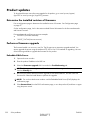
Product updates
DRAFT
1
Solve problems checklist
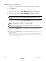
If the product is not responding correctly, complete the steps in the following checklist, in order. If the
product does not pass a step, follow the corresponding troubleshooting suggestions. If a step resolves
the problem, you can stop without performing the other steps on the checklist.
1.
Make sure that the control-panel display shows one of the following messages: Ready, Paused,
or SLEEP MODE ON. If no lights are illuminated or the display does not say Ready, Paused,
or Sleep Mode, use the Power-on checks section in the product service manual to troubleshoot
the problem.
2.
Check the cables.
a.
Check the cable connection between the product and the computer or network port. Make
sure that the connection is secure.
b.
Make sure that the cable itself is not faulty by using a different cable, if possible.
c.
Check the network connection.
3.
Ensure that the print media that you are using meets specifications.
4.
Print a configuration page. If the product is connected to a network, an HP Jetdirect page also
prints.
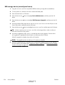
5.
6.
7.
a.
If the pages do not print, check that at least one tray contains print media.
b.
If the page jams in the product, see the jams section.
If the configuration page prints, check the following items.
a.
If the page prints correctly, the product hardware is working. The problem is with the
computer you are using, with the printer driver, or with the program.
b.
If the page does not print correctly, the problem is with the product hardware.
Does the image quality meet the user's requirements? If yes, see step 7. If no, check the following
items:
●
Print the print-quality (PQ) troubleshooting pages.
●
Solve the print-quality problems, and then see step 7.
At the computer, check to see if the print queue is stopped, paused, or set to print offline.
Windows: Click Start, click Settings, and then click Printers or Printers and Faxes.
Double-click the HP Color LaserJet CP5525n, HP Color LaserJet CP5525dn, or HP
Color LaserJet CP5525xh item depending on the product model installed.
-orMac OS X: Open Printer Setup Utility, and then double-click the line for the HP Color
LaserJet CP5525n, HP Color LaserJet CP5525dn, or HP Color LaserJet CP5525xh
item depending on the product model installed.
2
Solve problems
DRAFT
ENWW
8.
Verify that you have installed the HP Color LaserJet Enterprise CP5520 Printer Series printer driver.
Check the program to make sure that you are using the HP Color LaserJet Enterprise CP5520
Printer Series printer driver.
9.
Print a short document from a different program that has worked in the past. If this solution works,
the problem is with the program that you are using. If this solution does not work (the document
does not print) complete these steps:
a.
Try printing the job from another computer that has the product software installed.
b.
If you connected the product to the network, connect the product directly to a computer with
a USB cable. Redirect the product to the correct port, or reinstall the software, and select the
new connection type that you are using.
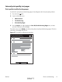
Menu map
Print the menu maps
1.
At the control panel, press the Home button
2.
Open the following menus:
●
Administration
●
Reports
●
Configuration/Status Pages
.
3.
Use the Down arrow button to highlight the Administration Menu Map item, and then
press the OK button to select it.
4.
se the Up arrow button
5.
Press the Home button
to highlight the Print item, and then press the OK button.
or Back button
to exit the menus.
Current settings pages
Printing the current settings pages provides a map of the user configurable settings that might be helpful
in the troubleshooting process.
Print the current settings pages
1.
At the control panel, press the Home button
2.
Open the following menus:
3.
ENWW
●
Administration
●
Reports
●
Configuration/Status Pages
Use the Down arrow button
OK button to select it.
.
to highlight the Current Settings Page item, and then press the
DRAFT
Menu map
3
4
4.
Use the Up arrow button
5.
Press the Home button
Solve problems
to highlight the Print item, and then press the OK button
or Back button
to exit the menus.
DRAFT
ENWW
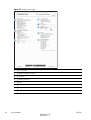
Control panel menus
To use all of the capabilities of this product, a firmware upgrade might be required. HP recommends
that you periodically go to www.hp.com/go/ljcp5520series_software to see if a new version of
firmware is available.
NOTE: Print a configuration page to determine the version of firmware currently installed in this
product.
Navigate the control-panel menus
Press the Home button to access the menus.
●
and down arrow button
●
Use the up arrow button
●
Press the OK button to select the menu item.
to highlight a desired menu item.
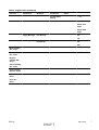
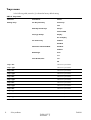
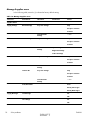
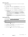
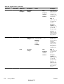
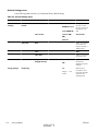
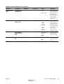
Sign In menu
Table 1 Sign In menu
First level
Second level
User Access Code
Access Code
Administrator Access Code
Access Code
Service Access Code
Access Code
Values
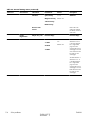
Retrieve Job From USB menu
Use the Retrieve Job From USB menu to view listings of jobs stored on an external USB memory
device.
Table 2 Retrieve Job From USB menu
First level
Second level
Retrieve Job From USB
Values
OK
Cancel
Select a File or Folder
Select from the provided list.
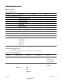
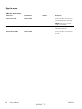
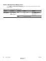
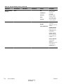
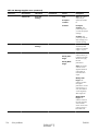
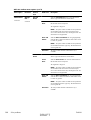
Retrieve Job From Device Memory menu
Use the Retrieve Job From Device Memory menu to view listings of jobs stored on the internal
product memory.
ENWW
DRAFT
Menu map
5
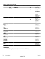
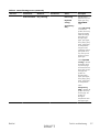
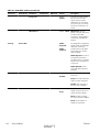
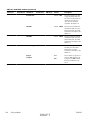
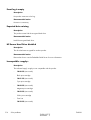
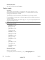
Table 3 Retrieve Job From Device Memory menu
First level
Second level
Third level
Values
Retrieve Job From Device
Memory
All Jobs (No PIN)
Print
Range: 1 – 9999
NOTE: Individual job names also
appear.
Default = 1
Delete
Select from the provided list.
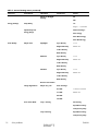
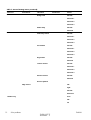
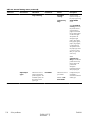
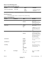
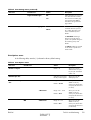
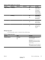
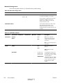
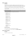
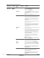
Supplies menu
In the following table, asterisks (*) indicate the factory default setting.
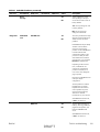
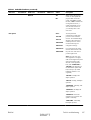
Table 4 Supplies menu
First level
Second level
Manage Supplies
Supplies Status
Supply Settings
Third level
Fourth level
Black Cartridge
Very Low
Settings
Values
Stop
Prompt to
continue*
Continue
Color Cartridges
Low Threshold
Settings
1-100%
Very Low
Settings
Stop
Prompt to
continue*
Continue
Low Threshold
Settings
Cyan Cartridge
1-100%
Magenta
Cartridge
Yellow Cartridge
Fuser
Very Low
Settings
Stop
Prompt to
continue*
Continue
Transfer Kit
Low Threshold
Settings
1-100%
Very Low
Settings
Stop
Prompt to
continue*
Continue
6
Solve problems
DRAFT
ENWW
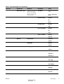
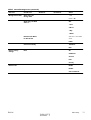
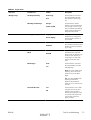
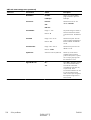
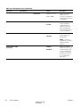
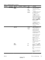
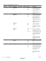
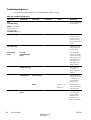
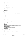
Table 4 Supplies menu (continued)
First level
Second level
Third level
Fourth level
Low Threshold
Settings
Color/Black Mix
Values
1-100%
Auto*
Mostly Color
Pages
Mostly Black
Pages
Supply Messages
Low Message
On*
Off
Level Gauge
On*
Off
Black Cartridge
OK: - Status
Cyan Cartridge
OK: - Status
Magenta
Cartridge OK: Status
Yellow Cartridge
OK: - Status
Toner Collection
Unit OK: - Status
Transfer Kit OK: Status
Fuser OK: Status
ENWW
DRAFT
Menu map
7
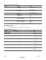
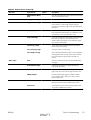
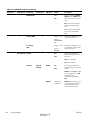
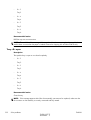
Trays menu
In the following table, asterisks (*) indicate the factory default setting.
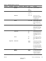
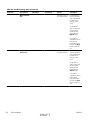
Table 5 Trays menu
First level
Second level
Values
Manage Trays
Use Requested Tray
Exclusively*
First
Manually Feed Prompt
Always*
Unless loaded
Size/Type Prompt
Display*
Do not display
Use another tray
Enabled*
Disabled
Alternative Letterhead Mode
Disabled*
Enabled
Blank Pages
Auto*
Yes
Override A4/Letter
Yes*
No
8
Tray 1 Size
Select from a provided list.
Tray 1 Type
Select from a provided list.
Tray 2 Size
Select from a provided list.
Tray 2 Type
Select from a provided list.
Tray 3 Size
Select from a provided list.
Tray 3 Type
Select from a provided list.
Tray 4 Size
Select from a provided list.
Tray 4 Type
Select from a provided list.
Tray 5 Size
Select from a provided list.
Tray 5 Type
Select from a provided list.
Tray 6 Size
Select from a provided list.
Tray 6 Type
Select from a provided list.
Solve problems
DRAFT
ENWW
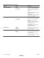
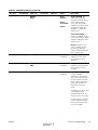
Administration menu
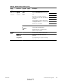
Reports menu
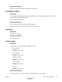
Table 6 Reports menu
First level
Second level
Configuration/Status Pages
Print
Third level
Values
Administration Menu Map
Configuration Page
Supplies Status Page
Usage Page
Paper Path Page
File Directory Page
Current Settings Page
Color Usage Job Log
Other Pages
Print
Demonstration Page
RGB Samples
CMYK Samples
PCL Font List
PS Font List
General Settings menu
In the following table, asterisks (*) indicate the factory default setting.
Table 7 General Settings menu
First level
Second level
Third level
Date/Time Settings
Date/Time Format
Date Format
Fourth level
Values
DD/MMM/YYYY
MMM/DD/YYYY*
YYYY/MMM/DD
Time Format
12 hour (AM/PM)*
24 hours
Date/Time
Date
Time
Time Zone
ENWW
DRAFT
Menu map
9
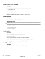
Table 7 General Settings menu (continued)
First level
Second level
Third level
Fourth level
Adjust for Daylight
Savings
Energy Settings
Values
On
Off*
Sleep Delay
15*
Range: 1 – 120 minutes
Optimum Speed/
Energy Usage
Faster First Page*
Save Energy
Save More Energy
Save Most Energy
Print Quality
Adjust Color
Highlights
Cyan Density
-5 to 5
Magenta Density
Default = 0
Yellow Density
Black Density
Midtones
Cyan Density
-5 to 5
Magenta Density
Default = 0
Yellow Density
Black Density
Shadows
Cyan Density
-5 to 5
Magenta Density
Default = 0
Yellow Density
Black Density
Restore Color Values
Image Registration
Adjust Tray <X>
Print Test Page
X1 Shift
-5.00 mm to 5.00 mm
Y1 Shift
Default = 0
X2 Shift
Y2 Shift
Auto Sense Mode
Tray 1 Sensing
Full sensing
Expanded sensing*
Transparency Only
Tray X Sensing
Expanded sensing*
Transparency Only
10
Solve problems
DRAFT
ENWW
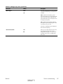
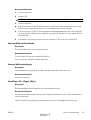
Table 7 General Settings menu (continued)
First level
Second level
Third level
Fourth level
Values
Adjust Paper Types
Select from a list of paper
types that the product
supports. The available
options are the same for
each paper type.
Print Mode
Select from a list of print
modes.
Default = Auto Sense
Mode
Resistance Mode
Normal*
Up
Down
Humidity Mode
Normal*
High
Fuser Temp Mode
Normal*
Up
Down
Paper Curl Mode
Normal*
Reduced
Optimize
Normal Paper
Standard*
Smooth
Light Media
Normal*
Smooth
Heavy Paper
Standard*
Smooth
Envelope Control
Normal*
Alternate 1
Alternate 2
Environment
Normal*
Low Temp
Line Voltage
Normal*
Low Voltage
Tray 1
Normal*
Alternate
Cleaning Control
Normal*
Alternate
ENWW
DRAFT
Menu map
11
Table 7 General Settings menu (continued)
First level
Second level
Third level
Background
Fourth level
Values
Normal*
Alternate 1
Alternate 2
Alternate 3
Media Temp
Normal*
Alternate
Uniformity Control
Normal*
Alternate 1
Alternate 2
Alternate 3
Pre-Rotation
Normal*
Alternate 1
Alternate 2
Alternate 3
Registration
Normal*
Alternate
Transfer Control
Normal*
Alternate 1
Alternate 2
Alternate 3
Moisture Control
Normal*
Alternate
Restore Optimize
Edge Control
Off
Light
Normal*
Maximum
Jam Recovery
Auto*
Off
On
12
Solve problems
DRAFT
ENWW
Table 7 General Settings menu (continued)
First level
Second level
Third level
Fourth level
Values
Manage Stored Jobs
Quick Copy Job
Storage Limit
1-300
Quick Copy Job Held
Timeout
Off*
Default = 32
1 hour
4 Hours
1 Day
1 Week
Default Folder Name
for Stored Jobs
Select from a list of folder
names.
Public*
Sort Stored Jobs By
Job Name*
Date
Restore Factory
Settings
Reset
All
Calibration
General
Print
Security
Restrict Color
Enable
Disable
Color if Allowed*
ENWW
DRAFT
Menu map
13
Retrieve From USB Settings menu
Table 8 Retrieve From USB Settings menu
First level
Second level
Values
Retrieve From USB Settings
Access Code
Enable*
Disable
Print Settings menu
In the following table, asterisks (*) indicate the factory default setting.
Table 9 Print Settings menu
First level
Second level
Manual Feed
Values
Enabled
Disabled*
Courier Font
Regular*
Dark
Wide A4
Enabled
Disabled*
Print PS Errors
Enabled
Disabled*
Print PDF Errors
Enabled
Disabled*
Personality
Auto*
PCL
POSTSCRIPT
PDF
PCL
Form Length
Range: 5 – 128
Default = 60
Orientation
Portrait*
Landscape
Font Source
Internal*
Soft
USB <X>
Font Number
Range: 0 – 999
Default = 0
14
Solve problems
DRAFT
ENWW
Table 9 Print Settings menu (continued)
First level
Second level
Values
Font Pitch
Range: 0.44 – 99.99
Default = 10
Font Point Size
Range: 4.00 – 999.75
Default = 12.00
Symbol Set
Select from a list of symbol sets.
Append CR to LF
No*
Yes
Suppress Blank Pages
No*
Yes
Media Source Mapping
Standard*
Classic
Print Options menu
In the following table, asterisks (*) indicate the factory default setting.
Table 10 Print Options menu
First level
Second level
Values
Number of Copies
Default = 1
Default Paper Size
Select from a list of sizes that the
product supports.
Default Custom Paper Size
Inches
X Dimension
Range: 2.99 – 12.28
Default = 12.28
Y Dimension
Range: 5.00 – 18.50
Default = 18.5
MM
X Dimension
Range: 76 – 312
Default = 312
Y Dimension
Range: 127 – 470
Default = 470
Sides
1-sided*
2-sided
ENWW
DRAFT
Menu map
15
Table 10 Print Options menu (continued)
First level
Second level
Values
Two-Sided Format
Book-style*
Flip-style
Enable Edge to Edge
Overrides
16
Solve problems
Enabled
Disabled*
DRAFT
ENWW
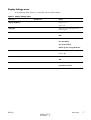
Display Settings menu
In the following table, asterisks (*) indicate the factory default setting.
Table 11 Display Settings menu
First level
Second level
Display Brightness
Values
Range: -10 to 10
Default = 0
Language
Select from a list of languages that the
product supports.
Show IP address
Display*
Hide
Sleep Mode
Disabled
Use sleep delay*
User sleep schedule
Balance power savings/Wait time
Inactivity Timeout
Range: 10 – 300 seconds
Default = 60
Clearable Warnings
On
Job*
Continuable Events
Auto continue (10 seconds)*
Press OK to continue
ENWW
DRAFT
Menu map
17
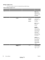
Manage Supplies menu
In the following table, asterisks (*) indicate the factory default setting.
Table 12 Manage Supplies menu
First level
Second level
Third level
Black Cartridge
Very Low Settings
Fourth level
Values
Supplies Status
Supply Settings
Stop
Prompt to continue*
Continue
Color Cartridges
Low Threshold
Settings
1-100%
Very Low Settings
Stop
Prompt to continue*
Continue
Low Threshold
Settings
Cyan Cartridge
1-100%
Magenta Cartridge
Yellow Cartridge
Fuser
Very Low Settings
Stop
Prompt to continue*
Continue
Transfer Kit
Low Threshold
Settings
1-100%
Very Low Settings
Stop
Prompt to continue*
Continue
Low Threshold
Settings
Color/Black Mix
1-100%
Auto*
Mostly Color Pages
Mostly Black Pages
Supply Messages
Low Message
On*
Off
Level Gauge
On*
Off
18
Solve problems
DRAFT
ENWW
Table 12 Manage Supplies menu (continued)
First level
Second level
Reset Supplies
New Fuser Kit
Third level
Fourth level
Values
No
Yes
New Transfer Kit
No
Yes
Manage Trays menu
In the following table, asterisks (*) indicate the factory default setting.
Table 13 Manage Trays menu
First level
Values
Use Requested Tray
Exclusively*
First
Manually Feed Prompt
Always*
Unless loaded
Size/Type Prompt
Display*
Do not display
Use another tray
Enabled*
Disabled
Alternative Letterhead Mode
Disabled*
Enabled
Blank Pages
Auto*
Yes
Override A4/Letter
Yes*
No
ENWW
DRAFT
Menu map
19
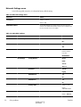
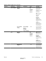
Network Settings menu
In the following table, asterisks (*) indicate the factory default setting.
Table 14 Network Settings menu
First level
Values
I/O Timeout
Range: 5 – 300 sec
Default = 15
Embedded Jetdirect
See the table that follows for details. These menus have the same
structure. If an additional HP Jetdirect network card is installed in the
EIO slot, then both menus are available.
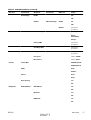
Table 15 Embedded Jetdirect
First level
Second level
Information
Print Sec Report
Third level
Fourth level
Fifth level
Values
Yes
No*
TCP/IP
Enable
On*
Off
Host Name
Use the arrow
buttons to edit the
host name.
NPIXXXXXX*
IPv4 Settings
Config Method
Bootp*
DHCP
Auto IP
Manual
Default IP
Auto IP*
Legacy
DHCP Release
Yes
No*
DHCP Renew
Yes
No*
Primary DNS
Range: 0 – 255
Default =
xxx.xxx.xx.xx
Secondary DNS
Range: 0 – 255
Default = 0.0.0.0
20
Solve problems
DRAFT
ENWW
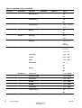
Table 15 Embedded Jetdirect (continued)
First level
Second level
Third level
IPv6 Settings
Enable
Fourth level
Fifth level
Values
On*
Off
Address
Manual Settings
Enable
On
Off*
Address
DHCPV6 Policy
Select from a
provided list.
Router Specified
Router
Unavailable*
Always
Security
Primary DNS
Select from a
provided list.
Secondary DNS
Select from a
provided list.
Proxy Server
Select from a
provided list.
Proxy Port
Default = 00080
Idle Timeout
Default = 0270
Secure Web
HTTPS Required*
HTTPS Optional
IPSEC
Keep
Disable*
802.1x
Reset
Keep*
Reset Security
Yes
No*
Diagnostics
Embedded Test
LAN HW Test
Yes
No*
HTTP Test
Yes
No*
SNMP Test
Yes
No*
ENWW
DRAFT
Menu map
21
Table 15 Embedded Jetdirect (continued)
First level
Second level
Third level
Fourth level
Data Path Test
Fifth level
Values
Yes
No*
Select All Tests
Yes
No*
Execution Time
Range: 1 – 60 hours
Default = 1
Execute
Yes
No*
Ping Test
Dest Type
IPv4
IPv6
Dest IPv4
Range: 0 – 255
Default =
127.0.0.1
Dest IPv6
Select from a
provided list.
Default = : : 1
Packet Size
Default = 64
Timeout
Default = 001
Count
Default = 004
Print Results
Yes
No*
Execute
Yes
No*
Ping Results
Packets Sent
Default = 00000
Packets Received
Default = 00000
Percent Lost
Default = 000
RTT Min
Default = 0000
RTT Max
Default = 0000
RTT Average
Default = 0000
Ping In Progress
Yes
No*
22
Solve problems
DRAFT
ENWW
Table 15 Embedded Jetdirect (continued)
First level
Second level
Third level
Fourth level
Fifth level
Refresh
Values
Yes
No*
Link Speed
Auto*
10T Half
10T Full
100TX Half
100TX Full
100TX Auto
1000TX Full
Troubleshooting menu
In the following table, asterisks (*) indicate the factory default setting.
Table 16 Troubleshooting menu
First level
Second level
Third level
Fourth level
Values
Exit Troubleshooting
NOTE: This item only
displays if you are
backing out of the
Troubleshooting menu.
Print Event Log
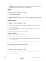
View Event Log
Print Quality Pages
Print PQ
Troubleshooting
Pages
Diagnostics Page
Color Band Test
Print Test Page
Copies
Range: 1 – 30
Default = 1
Diagnostic Tests
Disable Cartridge
Check
Paper Path Sensors
Paper Path Test
ENWW
Start Test
Print Test Page
Print
Source
Select from a list of the
available trays.
DRAFT
Menu map
23
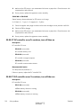
Table 16 Troubleshooting menu (continued)
First level
Second level
Third level
Fourth level
Test Duplex Path
Values
Off*
On
Number of Copies
Range: 1 – 500
Default = 1
Manual Sensor Test
Select from a list of the
product sensors.
Tray/Bin Manual
Sensor Test
Select from a list of the
product sensors.
Component Test
Select from a list of
available components.
Repeat
Off*
On
Print/Stop Test
Retrieve Diagnostic
Data
Export to USB
Diagnostic Files
Device Data File
Debug Information
File*
Include Crash Dumps
Off
On*
Cleanup Debug Info
Off
On*
General Debug Data
Device Maintenance menu
Backup/Restore menu
CAUTION: Data backup and restoration is the responsibility of the customer/administrator of the
product. Service personnel should not back up or restore customer data under any circumstances.
In the following table, asterisks (*) indicate the factory default setting.
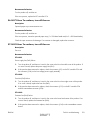
Table 17 Backup/Restore menu
First level
Second level
Third level
Values
Backup Data
Scheduled Backups
Enable Scheduling
Disabled*
Enabled
24
Solve problems
DRAFT
ENWW
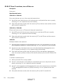
Table 17 Backup/Restore menu (continued)
First level
Second level
Third level
Values
Backup Time
Default = current time
Days Between Backups
Default = 1
Backup Now
Export Last Backup
Restore Data
Insert a USB drive that contains
the backup file.
Calibration/Cleaning menu
In the following table, asterisks (*) indicate the factory default setting.
Table 18 Calibration/Cleaning menu
First level
Second level
Auto Cleaning
Values
Off*
On
Cleaning Interval
Select from a list of cleaning intervals.
Auto Cleaning Size
Letter*
A4
Print Cleaning Page
Clean Laser Glass
Quick Calibration
Full Calibration
Delay Calibration at Wake/Power
On
Yes*
No
USB Firmware Upgrade menu
To display: At the product control panel, select the Device Maintenance menu, and then select the
USB Firmware Upgrade menu.
Insert a USB storage device with a firmware upgrade bundle into the USB port, and follow the onscreen instructions.
Service menu
The personal identification number (PIN; Service Access Code) used to access the Service menu is
11552010.
In the following table, asterisks (*) indicate the factory default setting.
ENWW
DRAFT
Menu map
25
First level
Second level
Third level
Values
Mono Cycle Counts
0*
User Access Code
Administrator Access
Code
Service Access Code
Print Event Log
View Event Log
Clear Event Log
Cycle Counts
Range: 0 – 9999999
Color Cycle Count
0*
Range: 0 – 9999999
Refurbish Cycle Count
0*
Range: 0 – 9999999
Serial Number
Service ID
20182*
Cold Reset Paper
Letter*
A4
New Registration Roller
Yes
No*
Media Sensor Value
0*
Range: 0 – 4095
Manual Laser Glass
Cleaning
Test Support
Continuous Print from
USB
Automatic Calibrations
Disabled
Enabled*
26
Solve problems
DRAFT
ENWW
Troubleshooting process
When the product malfunctions or encounters an unexpected situation, the product control panel alerts
you to the situation. This chapter contains information to help diagnose and solve problems.
●
Use the pretroubleshooting checklist to evaluate the source of the problem and to reduce the
number of steps that are required to fix the problem.
●
Use the troubleshooting flowchart to pinpoint the root cause of hardware malfunctions. The
flowchart guides you to the section of this chapter that contains steps for correcting the
malfunction.
Before beginning any troubleshooting procedure, check the following issues:
●
Are supply items within their rated life?
●
Does the configuration page reveal any configuration errors?
NOTE: The customer is responsible for checking supplies and for using supplies that are in good
condition.
Determine the problem source
When the product malfunctions or encounters an unexpected situation, the product control panel alerts
you to the situation. This section contains a pre-troubleshooting checklist to filter out many possible
causes of the problem. A troubleshooting flowchart helps you diagnose the root cause of the problem.
The remainder of this chapter provides steps for correcting problems.
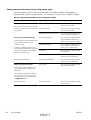
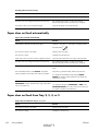
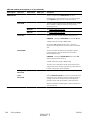
Pre-troubleshooting checklist
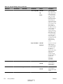
The following table includes basic questions to ask the customer to quickly help define the problem.
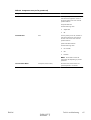
General topic
Questions
Environment
●
Is the product installed on a solid, level surface (+/- 1°)?
●
Is the power-supply voltage within ± 10 volts of the specified power source?
●
Is the power-supply plug inserted in the product and the outlet (not a power
strip)?
●
Is the operating environment within the specified parameters?
●
Is the product exposed to ammonia gas, such as that produced by diazo
copiers or office cleaning materials?
NOTE: Diazo copiers produce ammonia gas as part of the coping
processes. Ammonia gas (from cleaning supplies or a diazo copier) can have
an adverse affect on some product components (for example, the printcartridge OPC).
●
ENWW
Is the product exposed to direct sunlight?
DRAFT
Troubleshooting process
27
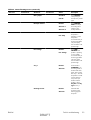
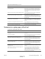
General topic
Questions
Media
●
Does the customer use only supported media?
●
Is the media in good condition (no curls, folds, or distortion)?
●
Is the media stored correctly and within environmental limits?
●
Is the amount of media in the tray within specifications?
●
Is the media correctly placed in the tray?
●
Are the paper guides aligned with the stack?
●
Is the cassette correctly installed in the product?
●
Is each print cartridge installed correctly?
●
Are original HP print cartridges installed?
●
Are the cartridges damaged?
●
Are the ITB and fuser correctly installed?
●
Is the ITB or fuser damaged?
Doors
●
Are the right and front doors closed?
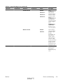
Condensation
●
Does condensation occur following a temperature change (particularly in
winter following cold storage)? If so, wipe affected parts dry or leave the
product on for 10 to 20 minutes.
●
Was a print cartridge opened soon after being moved from a cold to a warm
room? If so, allow the print cartridge to sit at room temperature for 1 to 2
hours.
●
Check for and remove any non-HP components (for example, print cartridges
or memory modules) from the product.
●
Check to see whether the hardware or software configuration has changed or
the problem is not associated with any specific software.
●
Remove the product from the network and ensure that the failure is associated
with the product before beginning troubleshooting.
●
For any print-quality issues, calibrate the product. See Calibrate the product
on page 103.
Input trays
Print cartridges
ITB and fuser
Miscellaneous
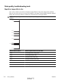
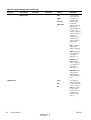
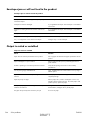
Troubleshooting flowchart
This flowchart highlights the general processes that you can follow to quickly isolate and solve product
hardware problems.
Each row depicts a major troubleshooting step. A “yes” answer to a question allows you to proceed to
the next major step. A “no” answer indicates that more testing is needed. Go to the appropriate section
in this chapter, and follow the instructions there. After completing the instructions, go to the next major
step in this troubleshooting flowchart.
28
Solve problems
DRAFT
ENWW
Table 19 Troubleshooting flowchart
1
Power on
Is the product on and does a readable
message display?
Yes
2
Control panel
messages
3
Event log
No
After the control panel display is functional, see step 2.
Does the message Ready display on the
control panel?
Yes
No
If an error message displays, see Interpret control-panel, status-alert
messages, and event code errors on page 158.
After the errors have been corrected, go to step 3.
Open the Troubleshooting menu and print
an event log to see the history of errors with
this product.
Does the event log print?
Yes
Follow the power-on troubleshooting checks. See Power subsystem
on page 30.
If the event log does not print, see Print an event log
on page 238.
If paper jams inside the product, see Clear jams on page 240.
If error messages display on the control panel when you try to print
an event log, see Print an event log on page 238.
No
After successfully printing and evaluating the event log, see step 4.
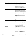
4
Information
pages
Open the Reports menu and print the
configuration pages to verify that all the
accessories are installed.
If accessories that are installed are not listed on the configuration
page, remove the accessory and reinstall it.
After evaluating the configuration pages, see step 5.
Are all the accessories installed?
Yes
5
Image quality
Does the print quality meet the customer's
requirements?
Yes
6
Interface
ENWW
No
No
Compare the images with the sample defects in the image defect
tables. See Print quality examples on page 269.
After the print quality is acceptable, see step 6.
Can the customer print successfully from the
host computer?
Verify that all I/O cables are connected correctly and that a valid
IP address is listed on the Jetdirect configuration page.
Yes. This is the end of
the troubleshooting
process.
If error messages display on the control panel, see Print an event
log on page 238.
No
When the customer can print from the host computer, this is the
end of the troubleshooting process.
DRAFT
Troubleshooting process
29
Power subsystem
Power-on checks
The basic product functions should start up when the product is plugged into an electrical outlet and the
power switch is pushed to the on position. If the product does not start, use the information in this
section to isolate and solve the problem.
Power-on troubleshooting overview
Turn on the product power. If the control panel display remains blank, random patterns display, or
asterisks remain on the control panel display, perform power-on checks to find the cause of the
problem.
During normal operation, the power supply, fuser, and formatter cooling fans begin to spin after the
product power is turned on. Place your hand over the holes in the left-side cover, near the formatter. If
the fan is operating, you will feel air passing out of the product. You can also lean close to the product
and hear the fan operating. You can also place your hand over the hole in the right-front lower corner.
If the fan is operating, you should feel air being drawn into the product. When these fans are
operational, the DC side of the power supply is functioning correctly.
After the fans are operating, the motor turn on and off (unless the right or front cover is open, a jam
condition is sensed, or the paper-path sensors are damaged). You might be able to visually and
audibly determine if the motors turn on and off.
If the fans and motors are operating correctly, the next troubleshooting step is to isolate print engine,
formatter, and control panel problems. Perform an engine test (see Engine test button on page 35). If
the formatter is damaged, it might interfere with the engine test. If the engine-test page does not print,
try removing the formatter and then performing the engine test again. If the engine test is then
successful, the problem is almost certainly with the formatter, the control panel, or the cable that
connects them.
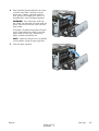
If the control panel is blank when you turn on the product, check the following items.
1.
Make sure that the product is plugged directly into an active electrical outlet (not a power strip)
that delivers the correct voltage.
2.
Make sure that the power switch is in the on position.
3.
Make sure that the fans run briefly, which indicates that the power supply is operational.
4.
Make sure that the control panel display wire harness is connected.
5.
Make sure that the formatter is seated and operating correctly. Turn off the product and remove
the formatter. Reinstall the formatter, and then verify that the heartbeat LED is flashing.
6.
Remove any HP Jetdirect or other EIO cards, and then try to turn the product on again.
NOTE: If the control panel display is blank, but the cooling fans run after the product power is turned
on, try printing an engine-test page to determine whether the problem is with the control-panel display,
formatter, or other product components. See Engine test button on page 35.
Power-on timing (approximate)
30
Solve problems
DRAFT
ENWW
Power-on timing from boot sequence to the Ready state might change as the firmware is upgraded.
●
00.00 seconds; power-button LED illuminates and fans rotate at high speed
●
00.06 seconds; control panel backlight illuminates and engine noises begin
●
00:10 seconds; HP logo appears on the control-panel display, boot sequence count appears on
the control-panel display
Boot sequence
1/8 = 10 seconds
◦
◦
2/8 = 15 seconds
NOTE: Depending on how the product was shut down, the product might stay at this point
for several minutes while the Disk Check process completes.
ENWW
◦
7/8 = 45 seconds
◦
8/8 = 50 seconds
●
01:30 seconds; fuser fan noise stops and engine noises stop
●
01:50 seconds; product enters the Ready state
DRAFT
Troubleshooting process
31
Tools for troubleshooting
Component diagnostics
LED diagnostics
LED, engine, and individual diagnostics can identify and troubleshoot product problems.
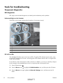
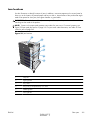
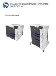
Understand lights on the formatter
Three LEDs on the formatter indicate that the product is functioning correctly.
2
3
1
1
Formatter connectivity LED (lit when formatter is correctly seated)
2
HP Jetdirect LEDs
3
Heartbeat LED
HP Jetdirect LEDs
The embedded HP Jetdirect print server has two LEDs. The yellow LED indicates network activity, and
the green LED indicates the link status. A blinking yellow LED indicates network traffic. If the green LED
is off, a link has failed.
For link failures, check all the network cable connections. In addition, you can try to manually configure
the link settings on the embedded print server by using the product control-panel menus.
32
1.
Press the Home button
2.
Press the Down arrow
to highlight the Administration menu, and then press the OK button.
3.
Press the Down arrow
button.
to highlight the Network Settings menu, and then press the OK
Solve problems
.
DRAFT
ENWW
4.
Press the Down arrow
button.
to highlight the Embedded Jetdirect option, and then press the OK
5.
Press the Down arrow
to highlight the Link Speed menu, and then press the OK button.
6.
Select the appropriate link speed, and then press the OK button.
Heartbeat LED
The heartbeat LED indicates that the formatter is functioning correctly. While the product is initializing
after you turn it on, the LED blinks on/off, on/off, pauses for a short duration, then repeats the
sequence. This sequence continues after the product has finished the initialization sequence.
Engine diagnostics
This section provides an overview of the engine diagnostics that are available in the HP Color LaserJet
Enterprise CP5520 Printer Series product. The product contains extensive internal diagnostics that help
in troubleshooting print quality, paper path, noise, component, and timing issues.
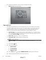
Defeating interlocks
Different tests can be used to isolate different types of issues. For component or noise isolation, you can
run the diagnostic test when the front and right doors are open. To operate the product with the doors
open, the door switch levers must be depressed to simulate a closed-door position.
WARNING! Be careful when performing printer diagnostics to avoid risk of injury. Only trained
service personnel should open the doors and run the diagnostics with the covers removed. Never touch
any of the power supplies when the printer is plugged in or turned on.
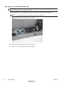
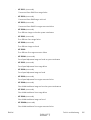
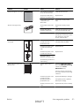
Defeat the right-door opening/closing sensor (PS15)
1.
ENWW
Open the right and front doors.
DRAFT
Tools for troubleshooting
33
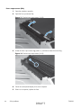
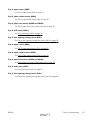
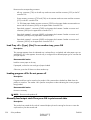
2.
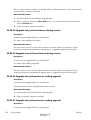
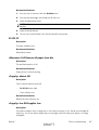
Insert a thin piece of paper into the right-door sensor slot (callout 1).
CAUTION: Using too thick of a piece of paper to activate this sensor might dislodge the photointerrupter body from its mounting bracket. Make sure you use a thin piece of paper to activate the
sensor.
Figure 1 Defeating door interlocks (1 of 2)
1
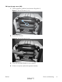
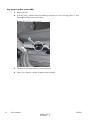
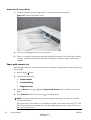
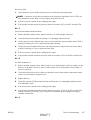
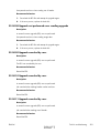
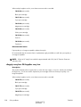
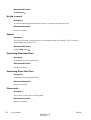
3.
Insert a folded piece of paper into the front door switch (callout 2). Wait until the product enters
the Ready state.
NOTE: The paper must be thick enough to depress and hold in place the sensor actuator arm.
Figure 2 Defeating door interlocks (2 of 2)
1
34
Solve problems
DRAFT
ENWW
Disable cartridge check
Use this diagnostic test to print internal pages or send an external job to the product when one or more
print cartridges are removed or exchanged. Consumable supply errors are ignored while the product is
in this mode. When the product is in this mode, you can navigate the troubleshooting menus and print
internal pages (the print quality pages will be the most useful). This test can be used isolate problems,
such as noise, and to isolate print-quality problems that are related to individual print cartridges.
NOTE: Color cartridges are not keyed and can be interchanged. An error will display on the control
panel if a print cartridge is installed in the wrong position. The Supplies Status menu will explain
which print cartridge is misplaced.
NOTE: Do not remove or exchange print cartridges and image drums until after you start the disable
cartridge check diagnostic.
1.
Press the Home
2.
Open the following menus:
3.
button.
●
Administration
●
Troubleshooting
●
Diagnostic Tests
Press the Down arrow
button .
to highlight DISABLE CARTRIDGE CHECK, and then press the OK
To exit this diagnostic test, press the Stop button
and then select EXIT TROUBLESHOOTING.
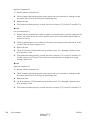
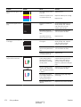
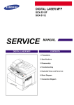
Engine test button
1.
Turn the product on.
2.
Use a fine-point tool, (for example a precision-slotted screwdriver with a 1 mm (0.04 in) blade
width) to press the engine test button.
NOTE: Access the engine test button through a hole in the rear cover.
ENWW
DRAFT
Tools for troubleshooting
35
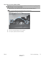
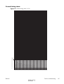
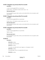
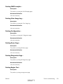
3.
An engine test page (lines in each of the print cartridge colors) prints.
Figure 3 Engine test button location
Paper-path test
This diagnostic test generates one or more test pages that you can use to isolate the cause of jams.
To isolate a problem, specify which input tray to use, specify whether to use the duplex path, and
specify the number of copies to print. Multiple copies can be printed to help isolate intermittent
problems. The following options become available after you start the diagnostic feature:
●
Print Test Page. Run the paper-path test from the default settings: Tray 2, no duplex, and one
copy. To specify other settings, scroll down the menu and select the setting, and then scroll back
up and select Print Test Page to start the test.
●
Source Tray. Select Tray 1, Tray 2, or the optional tray.
●
Test Duplex Path. Enable or disable two-sided printing.
NOTE: Duplex models only.
36
●
Number of Copies. Set the numbers of copies to be printed; the choices are 1,10, 50, 100, or
500.
1.
Press the Home
2.
Open the following menus:
button.
●
Administration
●
Troubleshooting
●
Diagnostic Tests
to highlight PAPER PATH TEST, and then press the OK button.
3.
Press the Down arrow
4.
Select the paper-path test options for the test you want to run.
Solve problems
DRAFT
ENWW
Manual sensor test
Use this diagnostic test to manually test the product sensors and switches. Each sensor is represented by
a letter and number on the control panel display.
1.
Press the Home button
2.
Open the following menus:
3.
●
Administration
●
Troubleshooting
●
Diagnostic Tests
Press the Down arrow
button.
.
to highlight the Manual Sensor Test item, and then press the OK
To exit this diagnostic, press the Stop button
, and then select EXIT TROUBLESHOOTING.
Menus cannot be opened during this test, so the OK button serves the same function as the
Stop button .
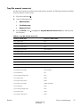
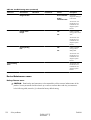
Table 20 Manual sensor diagnostic tests
ENWW
Sensor or switch name
Sensor or switch number
Front door opening/closing switch
PS14
Right door opening/closing sensor
PS15
A TOP (top of page) sensor
PS5
Fuser loop 1 sensor
PS7
Fuser loop 2 sensor
PS8
Fuser pressure-release sensor
PS9
Fuser output sensor
PS6
Developer alienation sensor
PS11
ITB alienation sensor
SW5
DRAFT
Tools for troubleshooting
37
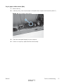
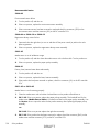
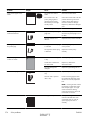
Front-door opening/closing switch (PS14)
NOTE: This switch is also activated by the right door. See Right-door opening/closing sensor (PS15)
on page 39. During this test, the right door must remain closed.
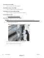
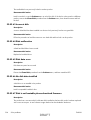
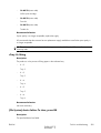
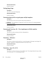
1.
Open the front-door assembly to disengage the front-door opening/closing switch.
2.
Close the front-door assembly, and then check the control panel on the product for sensor
response.
TIP: You can leave the front door open and use a folded piece of paper to activate the switch.
Figure 4 Test the front-door opening/closing switch
38
3.
Check the control-panel display for sensor response.
4.
If there is no response, replace the front-door opening/closing microswitch or the cable.
Solve problems
DRAFT
ENWW
Right-door opening/closing sensor (PS15)
NOTE: The front-door opening/closing switch (PS14) is also activated by the right door. During this
test, the front door must remain closed.
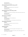
1.
Open the right-door assembly to disengage the right-door opening/closing photo-interrupter
sensor.
2.
Insert a piece of paper (callout 1) to override the front-door opening/closing switch (PS14).
NOTE: The paper must be thick enough to depress and hold in place the sensor actuator arm.
Figure 5 Test the right-door opening/closing switch (1 of 2)
1
ENWW
DRAFT
Tools for troubleshooting
39
3.
Insert a thin piece of paper (callout 1) to activate the right-door opening/closing sensor (PS15).
CAUTION: Using too thick of a piece of paper to activate this sensor might dislodge the photointerrupter body from its mounting bracket. Make sure you use a thin piece of paper to activate the
sensor.
Figure 6 Test the right-door opening/closing switch (2 of 2)
1
4.
40
If there is no response, replace the right-door sensor.
Solve problems
DRAFT
ENWW
TOP (top-of-page) sensor (PS5)
1.
Open the right door, and then locate the sensor flag (callout 1).
Figure 7 Test the TOP sensor (1 of 2)
1
2.
Activate the TOP sensor.
Figure 8 Test the TOP sensor (2 of 2)
ENWW
3.
Check the control-panel display for sensor response.
4.
If there is no response, replace the registration assembly.
DRAFT
Tools for troubleshooting
41
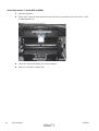
Fuser loop sensors 1 and 2 (PS7 and PS8)
1.
Open the right door.
2.
Slowly insert a piece of paper at the entrance of the fuser to activate the fuser loop sensors 1 and
2 underneath the fuser.
Figure 9 Test the fuser loop sensors
42
3.
Check the control-panel display for a sensor response.
4.
If there is no response, replace fuser.
Solve problems
DRAFT
ENWW
Fuser pressure-release sensor (PS9)
1.
Open the right-door assembly.
2.
Remove the fuser.
3.
Insert a piece of paper as shown to activate the fuser pressure-release sensor.
Figure 10 Test the fuser pressure-release sensor
ENWW
4.
Check the control-panel display for sensor response.
5.
If there is no response, replace the fuser drive assembly.
DRAFT
Tools for troubleshooting
43
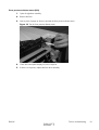
Fuser output sensor (PS6)
1.
Open the right-door assembly.
2.
Open the fuser jam-access flap.
Figure 11 Test the fuser output sensor (1 of 2)
3.
Locate the fuser output sensor flag (callout 1), and then activate the sensor flag.
Figure 12 Test the fuser output sensor (2 of 2)
1
44
4.
Check the control-panel display for a sensor response.
5.
If there is no response, replace the fuser.
Solve problems
DRAFT
ENWW
Developer alienation sensor (PS11)
This sensor is located inside the main-drive assembly and cannot be accessed for direct manual testing.
Use the paper path sensor test to test this sensor.
ENWW
1.
Press the Home button
2.
Open the following menus:
●
Administration
●
Troubleshooting
●
Diagnostic Tests
.
to highlight the Paper Path Sensors item, and then press the OK
3.
Press the Down arrow
button.
4.
Press the Down arrow to highlight Start, and then check the control-panel display for sensor
response (watch the developer alienation sensor (PS11) in the list).
5.
If there is no response, replace the main drive assembly.
DRAFT
Tools for troubleshooting
45
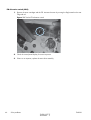
ITB alienation switch (SW5)
1.
Remove the toner cartridges and the ITB. Activate the senor by moving the flag located on the rear
ITB guide rail.
Figure 13 Test the ITB alienation switch
46
2.
Check the control-panel display for sensor response.
3.
If there is no response, replace the main drive assembly.
Solve problems
DRAFT
ENWW
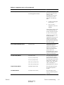
Tray/Bin manual sensor test
Use this test to test the tray and bin sensors and switches manually. The following illustrations and table
show the locations of these sensors.
1.
Press the Home button
2.
Open the following menus:
3.
●
Administration
●
Troubleshooting
●
Diagnostic Tests
.
Press the Down arrow
the OK button.
to highlight the Tray/Bin Manual Sensor Test item, and then press
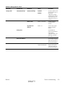
Table 21 Tray/Bin manual sensor test
ENWW
Sensor or switch name
Sensor or switch number
Tray 1 paper sensor
PS2
Tray 2 paper sensor
PS1
Tray 2 paper surface sensor
PS4
Tray 2 paper size switches
SW7 and SW 8
Tray 3 paper sensor
SR3
Tray 3 paper surface sensor
SR2
Tray 3 paper size switches
SW2 and SW3
Tray 3 feed sensor
SR1
Tray 3 door opening/closing sensor
SW1
Tray 4 paper sensor
SR3
Tray 4 paper surface sensor
SR2
Tray 4 paper size switches
SW2 and SW3
Tray 4 feed sensor
SR1
Tray 4 opening/closing sensor1
SW1
Tray 5 paper sensor
SR83
Tray 5 paper surface sensor
SR82
Tray 5 paper size switches
SW82 and SW83
Tray 5 feed sensor
SR81
Tray 5 opening/closing sensor1
SW1
Tray 6 paper sensor
SR93
Tray 6 paper surface sensor
SR92
DRAFT
Tools for troubleshooting
47
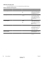
Table 21 Tray/Bin manual sensor test (continued)
1
48
Sensor or switch name
Sensor or switch number
Tray 6 paper size switches
SW92 and SW93
Tray 6 feed sensor
SR91
Tray 6 opening/closing sensor1
SW1
Output bin full sensor
PS10
Tray 4, Tray 5, and Tray 6 use the same opening/closing sensor (SW1) on the right door of the accessory.
Solve problems
DRAFT
ENWW
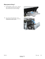
Tray 1 paper sensor (PS2)
1.
Open Tray 1.
2.
Locate the Tray 1 paper-present sensor flag (callout 1), and then toggle the sensor flag to activate
the sensor.
Figure 14 Test the Tray 1 paper present sensor
1
ENWW
3.
Check the control-panel display for sensor response.
4.
If there is no response, replace the paper pickup assembly.
DRAFT
Tools for troubleshooting
49
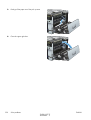
Tray 2 paper present sensor (PS1)
1.
Remove the tray.
2.
In the tray cavity, release the spring loaded tray-present lever to lower the flag (callout 1), and
then toggle the flag to activate the sensor.
Figure 15 Test the tray 2 paper sensor
1
50
3.
Check the control-panel display for sensor response.
4.
If there is no response, replace the last paper detect sensor.
Solve problems
DRAFT
ENWW
Tray 2 paper surface sensor (PS4)
1.
Remove the tray.
2.
In the tray cavity, insert a slip of paper in the photo sensor receptor and transmitter (callout 1).
Figure 16 Tray 2 paper surface sensor
1
ENWW
3.
Check the control-panel display for sensor response.
4.
If there is no response, replace the lifter drive assembly.
DRAFT
Tools for troubleshooting
51
Tray 2 paper size switches (SW7 and SW8)
NOTE: These switches also detect cassette presence. If these switches fail, the message Tray <X>
open could appear on the control-panel display.
1.
Remove the tray. From inside the tray cavity, push any of the switch buttons (callout 1).
TIP: You can test these sensors by opening, and then closing the tray.
Figure 17 Test the Tray 2 paper size switches
52
2.
Check the control-panel display for sensor response.
3.
If there is no response, replace the lifter assembly.
Solve problems
DRAFT
ENWW
Tray 3 paper sensor (SR3)
1.
Remove the tray.
2.
In the tray cavity, release the spring loaded tray-present lever to lower the flag (callout 1), and
then toggle the flag to activate the sensor.
Figure 18 Test Tray 3 paper sensor
1
ENWW
3.
Check the control-panel display for sensor response.
4.
If there is no response, replace the paper pickup assembly.
DRAFT
Tools for troubleshooting
53
Tray 3 paper surface sensor (SR2)
1.
Remove the tray.
2.
In the tray cavity, release the spring loaded tray-present lever to lower the flag (callout 1), and
then toggle the flag to activate the sensor.
Figure 19 Test Tray 3 paper sensor
1
54
3.
Check the control-panel display for sensor response.
4.
If there is no response, replace the paper pickup assembly.
Solve problems
DRAFT
ENWW
Tray 3 paper size sensors (SW2 and SW3)
NOTE: These switches also detect cassette presence. If these switches fail, the message Tray <X>
open could appear on the control-panel display.
1.
Remove the tray. From inside the tray cavity, push any of the switch buttons (callout 1).
TIP: You can test these sensors by opening, and then closing the tray.
Figure 20 Test Tray 3 paper size sensors
1
ENWW
2.
Check the control-panel display for sensor response.
3.
If no response, replace the lifter drive assembly.
DRAFT
Tools for troubleshooting
55
Tray 3 feed sensor (SR1)
1.
Open the paper-feeder door.
2.
Insert a piece of paper as shown to activate the feed sensor.
TIP: Use stiff paper when performing this test (for example a business card or index card).
Figure 21 Test the Tray 3 feed sensor
56
3.
Check the control-panel display for sensor response.
4.
If no response, replace the paper pickup assembly.
Solve problems
DRAFT
ENWW
Tray 3 door opening/closing sensor (SW1)
1.
Open and then close the paper-feeder door to activate the sensor. The tab on the door (callout 1)
activates the senor (callout 2).
Figure 22 Test the Tray 3 door opening/closing sensor
2
1
ENWW
2.
Check the control-panel display for sensor response.
3.
If no response, replace the button switch.
DRAFT
Tools for troubleshooting
57
Tray 4 paper sensor (SR3)
See Tray 3 paper sensor (SR3) on page 53.
Tray 4 paper surface sensor (SR2)
See Tray 3 paper surface sensor (SR2) on page 54.
Tray 4 paper size sensors (SW2 and SW3)
See Tray 3 paper size sensors (SW2 and SW3) on page 55.
Tray 4 feed sensor (SR1)
See Tray 3 feed sensor (SR1) on page 56.
Tray 4 door opening/closing door sensor (SW1)
NOTE: Tray 4, Tray 5, and Tray 6 use the same opening/closing door sensor (SW1).
1.
Open and then close the paper-feeder door to activate the sensor (the tab on the door (callout 1)
activates the senor (callout 2).
Figure 23 Test the Tray 4 door opening/closing sensor
2
1
58
2.
Check the control-panel display for sensor response.
3.
If no response, replace the button switch.
Solve problems
DRAFT
ENWW
Tray 5 paper sensor (SR83)
See Tray 3 paper sensor (SR3) on page 53.
Tray 5 paper surface sensor (SR82)
See Tray 3 paper surface sensor (SR2) on page 54.
Tray 5 paper size sensors (SW82 and SW83)
See Tray 3 paper size sensors (SW2 and SW3) on page 55.
Tray 5 feed sensor (SR81)
See Tray 3 feed sensor (SR1) on page 56.
Tray 5 door opening/closing sensor (SW1)
See Tray 4 door opening/closing door sensor (SW1) on page 58.
Tray 6 paper sensor (SR93)
See Tray 2 paper present sensor (PS1) on page 50.
Tray 6 paper surface sensor (SR92)
See Tray 3 paper surface sensor (SR2) on page 54.
Tray 6 paper size sensors (SW92 and SW93)
See Tray 3 paper size sensors (SW2 and SW3) on page 55.
Tray 6 feed sensor (SR91)
See Tray 3 feed sensor (SR1) on page 56.
Tray 6 door opening/closing sensor (SW1)
See Tray 4 door opening/closing door sensor (SW1) on page 58.
ENWW
DRAFT
Tools for troubleshooting
59
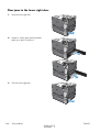
Output-bin-full sensor (PS10)
1.
Locate the output-bin-full sensor flag (callout 1), and then activate the sensor flag.
Figure 24 Test the output-bin-full sensor
1
2.
Check the control-panel display for sensor response.
3.
If there is no response, examine the flag at the left end of the output bin full sensor flag. If the flag
is broken, replace the paper delivery assembly. If the flag is not broken, replace the fuser gear
assembly.
Paper-path sensors test
This test displays the status of each paper-path sensor and allows viewing of sensor status while printing
internal pages.
1.
Press the Home
2.
Open the following menus:
button.
●
Administration
●
Troubleshooting
●
Diagnostic Tests
to highlight the Paper Path Sensors option, and then press the OK
3.
Press the Down arrow
button.
4.
Select Start Test. Press the down arrow
to see the test results.
NOTE: Exiting the Paper-path sensor test menu and then reentering it will clear the test values
from the previous test.
Viewing the sensor status before you activate the test should show that the sensors PS9, PS11 and
SW5 have already been activated. After running the Paper-path sensor test, sensor PS9 does not
show any activation status.
60
Solve problems
DRAFT
ENWW
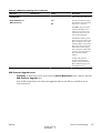
Table 22 Paper-path sensors diagnostic tests
Sensor name
Sensor number
TOP (top of page) sensor
PS5
Fuser loop sensor
PS7
Fuser loop sensor
PS8
Fuser delivery sensor
PS6
Output bin full sensor
PS10
Developer alienation
PS11
Fuser pressure-release sensor
PS9
Primary transfer-roller-disengagement sensor
SW5
Print/stop test
Use this diagnostic test to isolate the cause of problems such as image-formation defects and jams
within the engine. During this test you can stop the paper anywhere along the product paper path. The
test can be programmed to stop printing internal pages or an external print job when the paper
reaches a certain position. The test can also be programmed to stop from 0 to 60,000 ms. If the timer
is set to a value that is greater than the job-print time, you can recover the product in one of two ways.
●
After the print job is completed press the Stop button
before the timer times out.
●
After the timer times out, press the Stop button
and return it to a normal state.
to return to the Diagnostic Tests menu
. Activate the door switch to restart the engine
When the timer trips, the control panel display shows the message Printing stopped To continue,
press OK. Pressing the Home button will print the previously selected job. If you do not want the
previous job to print, press the Stop button
first, and then press the Home button .
NOTE: Do not try to perform a print/stop test while the product is calibrating, because you will be
required to power-cycle the product. If a jam message displays on the control panel during testing,
activate the door switch.
Component tests
Component test (special-mode test)
This test activates individual parts independently to isolate problems.
Each component test can be performed once or repeatedly. If you select the Repeat option (at the end
of the menu), the test cycles the component on and off. This process continues for two minutes, and then
the test terminates.
ENWW
DRAFT
Tools for troubleshooting
61
NOTE: The front or side door interlocks must be defeated to run the component tests. Some tests may
require that the ITB and print cartridges be removed. The control panel display prompts you to remove
some or all cartridges during certain tests.
1.
Press the Home button .
2.
Open the following menus:
●
Administration
●
Troubleshooting
●
Diagnostic Tests
to highlight the Component Test item, and then press the OK button.
3.
Press the Down arrow
4.
Select the component test options for the test you want to run.
Table 23 Component tests (1 of 2)
Component test
Component tested
Comments
Transfer Motors
M1 (ITB motor)
Drives the ITB motor and drum
motor together at a specified
speed for 5 seconds.
M2 (drum motor)
Belt Only
M1 (ITB motor)
Drives ITB drive motor at a
specified speed for 5 seconds.
Developer Motors
M1 (ITB motor)
Drives the ITB motor at a
specified speed for 5 seconds.
M3 (developer motor)
Drives the developer motor at
a specified speed for 5
seconds (drives 3 times).
Cartridge Motors
M1 (ITB motor)
M2 (drum motor)
Drives the ITB motor at a
specified speed for 5 seconds.
Drives the drum motor at a
specified speed for 5 seconds
(drives 3 times).
62
Fuser Motor
M4
Drives the fuser motor at a
specified speed for 5 seconds.
Alienation Motor (cartridge)
M6 (developer alienation motor)
Drives the developer
disengagement motor and
engages or disengages the
developer (drives the motor
four times). If the home
position of the developer is not
commanded within 5 seconds,
the product brings the
developer to its home position.
Solve problems
DRAFT
ENWW
Table 23 Component tests (1 of 2) (continued)
Component test
Component tested
Comments
ITB Contact/Alienation Motor
M4 (fuser motor)
Drives the fuser motor M4
(drives the motor four times)
and the T1 roller
disengagement solenoid SL5,
and brings the T1 roller to
either one of the following
states:
SL5 (disengagement solenoid)
●
4 rollers are disengaged
(home position)
●
Only K T1 roller is
engaged or 4 rollers are
engaged
If home position of the T1 roller
is not commanded within 10
seconds, the printer moves the
T1 roller to its home position.
Additionally, the printer keeps
the state of 4 rollers
engagement so that the service
technician can access and
manually clean the dust-proof
glass (open the front door and
remove the cartridge).
Fuser Contact/Alienation Drive
M4 (fuser motor)
Reverses the fuser motor to
rotate the fuser pressure
release cam and pressurize or
depressurize the pressure
roller. If home position of the
pressure roller is not
commanded within 5 seconds,
the printer brings the pressure
roller to its home position.
Tray<X> Pickup Motor
M5 (pickup motor)
Drives the pickup motor M5,
the 500 sheet paper feeder
pickup motor M1, and each of
the 3x500 paper deck cassette
pickup motors, cassette 1 M1,
cassette 2 M81, and cassette
3 M91 individually at a
specified speed for 5 seconds.
M1 (Tray 3 pickup motor)
M1 (Tray 4 pickup motor)
M81 (Tray 5 pickup motor)
M91 (Tray 6 pickup motor)
ENWW
DuplexerPickup Motor
M8 (duplex pickup motor)
Drives the duplex feed motor
at a specified speed for 5
seconds.
Switchback Motor
M7 (duplex reverse motor)
Drives the duplex reverse
motor at a specified speed for
5 seconds.
DRAFT
Tools for troubleshooting
63
Table 23 Component tests (1 of 2) (continued)
Component test
Component tested
Comments
Tray<X> Pickup Solenoid
SL2 (Tray 1 pickup solenoid)
Drives the Tray 1 pickup
solenoid SL2, the Tray 2
cassette pickup solenoid SL1,
the 500 sheet feeder pickup
solenoid SL1, and each of the
3x500 paper deck cassette
solenoids, cassette 1 SL1,
cassette 2 SL82, and cassette
3 SL92, individually for 5
seconds.
SL1 (Tray 2 pickup solenoid)
SL1 (Tray 3 pickup solenoid)
SL1 (Tray 4 pickup solenoid)
SL82 (Tray 5 pickup solenoid)
SL92 (Tray 6 pickup solenoid)
Switchback Flapper Solenoid
SL3 (duplex reverse solenoid)
Drives the duplex reverse
solenoid for 10 seconds.
Additional component tests
The following tests are not supported in the firmware. These component tests are accomplished by
manipulating or observing the product during operation or when the power is turned on.
Table 24 Component tests (2 of 2)
Component test
Component tested
Comments
Paper Deck Cassette Lifter Motor
M9 (Tray 2 lifter drive assembly)
Open and then close a paper tray.
Listen at the back side of the product for
the sound of the lift motor for that tray.
M2 (Tray 3 lifter drive assembly)
M2 (Tray 4 lifter drive assembly)
M82 (Tray 5 lifter drive assembly)
M92 (Tray 6 lifter drive assembly)
Power Supply Fan
FM1
If the lift motor does not make a sound
and the paper surface sensor for that
tray passes a sensor test (see Tray/Bin
manual sensor test on page 47), replace
the lifter drive assembly.
Turn the product power off, and then on.
Listen at the left-front-lower corner area
of the print engine for fan noise while
the product initializes.
Full/half speed intake fan
Cools the following areas:
64
Solve problems
DRAFT
●
low-voltage power supply area
●
face-down bin
●
delivery bin
●
laser scanner area
ENWW
Table 24 Component tests (2 of 2) (continued)
Component test
Component tested
Comments
Fuser Fan
FM2
Turn the product power off, and then on.
Listen at the front-right-lower corner of
the print engine for fan noise while the
product initializes.
Full speed intake fan
Cools the following areas:
Formatter Fan
FM3
●
duplex feed
●
ITB
Turn the product power off, and then on.
Listen at the back-lower center area of
the rear cover for fan noise while the
product initializes.
Speed controlled intake fan
Cools the following areas:
●
DC controller
●
ICB
●
formatter
NOTE: The formatter controls the
speed of this fan depending on product
operations.
Laser Scanner Motor
ENWW
M10 (laser/scanner motor)
DRAFT
Drives the laser/scanner motor at a
specified speed for 10 seconds.
Tools for troubleshooting
65
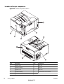
Diagrams
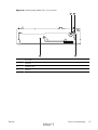
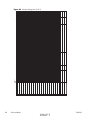
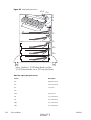
Block diagrams
Figure 25 Product cross section
1
2
3 4
5
6
7
8
9
10
11
12
13
14
15
22
21
20
19 18 17 16
Item
Description
Item
Description
1
ITB
12
MP tray pickup roller
2
Primary transfer roller
13
MP tray separation pad
3
Delivery roller
14
Cassette pickup roller
4
Duplex reverse roller (duplex models only)
15
Cassette separation roller
5
Duplex flapper (duplex models only
16
Feed roller
6
Pressure roller
17
Media sensor
7
Duplex feed roller (duplex models only)
18
Registration roller
8
IFuser
19
Registration density sensor
9
Fuser sleeve
20
Cassette
10
Secondary transfer roller
21
Photosensitive drum
ITB drive roller
66
Solve problems
Laser/scanner assembly
DRAFT
ENWW
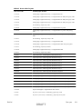
Figure 26 Optional paper feeder (Tray 3) cross section
1
3
4
ENWW
1
Pickup roller
2
Feed roller
3
Separation roller
4
Cassette
2
DRAFT
Tools for troubleshooting
67
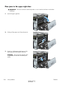
Plug/jack locations
1
2
3
4
68
1
Hi-Speed USB 2.0 printing port
2
Local area network (LAN) Ethernet (RJ-45) network port
3
USB port for a third-party device
4
EIO interface expansion slot
Solve problems
DRAFT
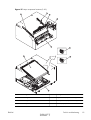
ENWW
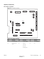
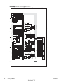
Location of connectors
DC controller connections
Figure 27 DC controller connections
J93
J131
J181
J81
J101
J172
J171
J102
J91
J33
SW301
J21
J92
J151
J161
J51
J112
J121
J63
J122
J25
J152
J73
J26
J111
J71
J192
J72
J62
J61
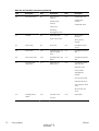
Table 25 DC controller connections
Item
Description
Item
Description
Item
Description
J21
DC controller power
J73
Secondary transfer
J122
Top of page sensor
J25
Low-voltage power
supply
J81
ITB motor
J131
Fuser
Fuser motor
Drum motor
Developing motor
ENWW
DRAFT
Tools for troubleshooting
69
Table 25 DC controller connections (continued)
Item
Description
Item
Description
Item
Description
J33
Environment sensor
J91
Duplex reverse
solenoid
J151
Cassette paper size
Cassette paper
presence
Cassette pickup
solenoid
Cassette lifter motor
Pickup motor
Developing
disengagement motor
J51
Formatter
J92
Duplex feed motor
J152
Duplex reverse motor
MP tray paper
presence
MP tray pickup
solenoid
J61
Laser scanner
J93
Driver PCA
J161
Cartridge toner level
sensors
J62
Laser scanner
J101
Cartridge memory tag
(yellow, magenta,
cyan)
J171
Cartridge pre-exposure
LEDs
J63
Laser scanner motor
J102
Cartridge memory tag
(black)
J172
Cartridge pre-exposure
LEDs
J71
Developing highvoltage PCA
J111
Registration and
density sensor
J181
Cartridge drum homeposition sensors
Right door switch
Primary transfer
disengagement
solenoid
Fuser pressure release
Output bin full sensor
Toner collection unit full
sensor
ITB waste toner full
sensor
J72
70
Solve problems
Cartridge primary
transfer
J121
Front door switch
J192
Paper feeder
Fuser fan
DRAFT
ENWW
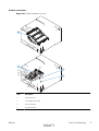
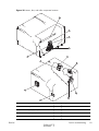
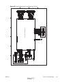
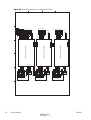
Product connections
Figure 28 Product connections (1 of 6)
J832
J831
1
2
J105
J110
J302
J106
3
J203
4
J304
J305
J303
J1001
J502
J301
ENWW
Item
Description
1
Laser scanner unit
2
Low-voltage power supply
3
Power switch PCA
4
Environment sensor
DRAFT
Tools for troubleshooting
71
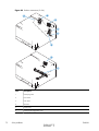
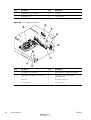
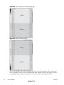
Figure 29 Product connections (2 of 6)
1
2
J515
3
J516
J514
J517
J518
4
5
J523
6
7
J553
8
J522
J739
J742
72
Item
Description
1
Developing motor
2
Drum motor
3
Fuser motor
4
ITB motor
5
Pickup motor
6
Developing disengagement motor
Solve problems
DRAFT
ENWW
Item
Description
7
Drive unit
8
Lifter drive unit
Figure 30 Product connections (3 of 6)
2
1
3
4
J1001
5
6
J557
J558
J559
J560
ENWW
Item
Description
1
High-voltage power supply imaging (developing) PCA
2
High-voltage power supply 1st transfer PCA
3
Driver PCA
DRAFT
Tools for troubleshooting
73
Item
Description
4
DC controller PCA
5
High-voltage power supply 2nd transfer PCA
6
Toner remaining detect PCA
Figure 31 Product connections (4 of 6)
J554
1
J535
J538
2
74
Item
Description
1
Registration sensor assembly
2
Paper pickup drive unit
Solve problems
DRAFT
ENWW
Figure 32 Product connections (5 of 6)
1
J704
J552
J522
J109
5
6
J525
J106
J51
J708
J142
J524
4
2
3
ENWW
Item
Description
1
Fuser
2
24V interlock switch
3
Fuser fan
4
Power supply fan
5
ICB PCA
6
Formatter fan
DRAFT
Tools for troubleshooting
75
Figure 33 Product connections (6 of 6)
1
J736
J152
2
J706
3
J705
76
Item
Description
1
Right door assembly
2
ITB rear guide
3
ITB front guide
Solve problems
DRAFT
ENWW
Figure 34 Paper feeder connections
1
J2006
J707
J706
J704
2
J733
Paper feeder controller PCA
J734
J705
3
J701
J702
J703
J752
J703
J751
ENWW
Item
Description
1
Paper feeder lifter-drive assembly
2
Paper feeder PCA
3
Paper feeder paper-pickup assembly
DRAFT
Tools for troubleshooting
77
Locations of major components
Figure 35 External component locations
1
2
5
4
6
3
9
8
7
78
Item
Description
Item
Description
1
Right-rear cover
6
Top cover
2
Right-door assembly
7
Left cover
3
Right-front cover
8
Rear cover
4
Front-door assembly
9
Toner collection unit access-door
5
Cassette (Tray 2)
Solve problems
DRAFT
ENWW
Figure 36 Major component locations (1 of 3)
2
1
3
4
5
ENWW
Item
Description
1
Laser scanner unit
2
Toner collection unit
3
Fuser
DRAFT
Tools for troubleshooting
79
80
Item
Description
4
Main drive unit
5
Lifter drive unit
Solve problems
DRAFT
ENWW
Figure 37 Major component locations (2 of 3)
2
1
3
4
5
6
9
7
8
ENWW
Item
Description
Item
Description
1
ITB front guide unit
6
Duplex drive unit (duplex models only)
2
ITB rear guide unit
7
Delivery drive unit (simplex models only)
3
Delivery unit
8
Cassette (Tray 2)
DRAFT
Tools for troubleshooting
81
Item
Description
Item
Description
4
Toner collection unit full sensor
9
ITB unit
5
Cassette pickup drive unit
Figure 38 Major component locations (3 of 3)
2
1
3
82
Item
Description
1
Waste toner carrier unit
2
Formatter
3
Fuser drive unit
Solve problems
DRAFT
ENWW
Figure 39 Motors, fans, and rollers component locations
1
2
3
4
5
7
6
8
12
9
10
11
ENWW
Item
Description
Item
Description
1
Secondary transfer roller unit
7
Drum motor
2
MP tray (Tray 1) pickup roller
8
Fuser motor
3
MP tray (Tray 1) separation pad
9
ITB motor
4
Cassette (Tray 2) separation roller unit
10
Developing disengagement motor
DRAFT
Tools for troubleshooting
83
Item
Description
Item
Description
5
Cassette (Tray 2) pickup roller unit
11
Fuser fan
6
Developing motor
12
Power supply fan
Figure 40 PCA component locations
2
1
3
4
5
6
8
7
84
Item
Description
Item
Description
1
Low-voltage power-supply PCA
5
High-voltage power supply 2nd transfer PCA
2
High-voltage power supply 1st transfer PCA
6
High-voltage power supply imaging
(development) PCA
3
Driver PCA
7
Environment sensor PCA
4
DC controller PCA
8
Power switch PCA
Solve problems
DRAFT
ENWW
ENWW
DRAFT
23 K developing bias
22 C developing bias
21 M developing bias
20 Y developing bias
19 K primary charging bias
18 Y/M/C primary charging bias
17 Fuser heater
16 Developer disengagement motor
15 Developer motor
14 Drum motor
13 Fuser motor
12 ITB motor
11 Pickup motor
10 Scanner motor
9 K video signal
8 C video signal
7 M video signal
6 Y video signal
5 Top of paper signal
4 Fuser output sensor
3 Top of paper sensor
2 Cassette pickup solenoid
1 Print command
Power ON
Two consecutive prints on letter paper
WAIT
STBY
INTR
PRINT
LSTR
STBY
General timing charts
Figure 41 General timing chart (1 of 2)
Tools for troubleshooting
85
86
Solve problems
30 Fuser fan
29 Power fan
28 T2 bias
27 K T1 bias
26 C T1 bias
25 M T1 bias
24 Y T1 bias
Power ON
WAIT
STBY
INTR
PRINT
LSTR
STBY
Figure 42 General timing chart (2 of 2)
DRAFT
ENWW
ENWW
DRAFT
Tools for troubleshooting
87
Formatter fan
FM3
2
1
2
1
J102
1
2
2
1
J719DH
J719D
7
6
3
1
2
1
2
1
2
J718H
J718D
1
8
2
7
3
6
J718L
3ST
MEM3
4
5
ICB
5
4
GND
F P_ 3 . 3 V
F PO
F PI
F PCL K
/ F PCS
GND
F P_ 5 V
1
2
1
6
5
4
3
2
1
2
1
1
2
1
2
J716H
J716D
J191
6
7
J716L
1ST
MEM1
1
6
2
5
3
4
J717H
J717D
3
4
J717L
J101
2
1
2
2ST
MEM2
J51
23
J301
2
5
J305ICB
1
6
J2
USB
GND
VBUS
DD+
GND
GND
2
J303ICB
1
8
2
10
17
1
3
J142
11
15
18
J1
J719L
4ST
MEM4
GND
/FAN3LK
FAN3PWM
1
2
3
4
5
6
7
8
9
12
13
14
16
19
20
21
1
3
1
4
2
2
2
3
1ST
J548
5
3
1
3
2
1
5
8
1
J558H
J558D
3
1
7
2
2
2
J62
19
J732
6
5
4
3
1
3
1
2
2
2
2
4ST
J551
J559H
J559D
J559L
3
1
3
J560H
J560D
J560L
1
1
3
3
K Toner
level sensor
18
17
16
1
15
21
20
19
18
17
16
15
14
13
21
12
11
J71
7
J2001
8
4
5
6
5
1
4
2
3
2
3
Paper feeder
J733DH
J192
3
2
17
J61
J733DA
17
J731
12
11
1
2
3
4
5
6
7
8
9
10
11
12
13
14
15
16
17
18
19
1
2
3
4
5
6
7
8
9
10
18
13
+3. 3V
SCL
SDA
GND
DAT A_ M
/ DAT A_ M
GND
CT L 1 _ M
CT L 0 _ M
PWM- M
GND
DAT A_ Y
/ DAT A_ Y
GND
CT L 1 _ Y
CT L 0 _ Y
PWM- Y
GND
+5V
GND
/ BD
GND
DAT A_ C
/ DAT A_ C
GND
CT L 1 _ C
CT L 0 _ C
PWM- C
GND
DAT A_ K
/ DAT A_ K
GND
CT L 1 _ K
CT L 0 _ K
PWM- K
GND
+5V
11
J631
Developing high-voltage
power supply PCA
19
1
J831
DC controller PCA
19
J832
3
2
14
19
3ST
J550
J558L
3
1
3
6
8
11
15
4
15
J632
C Toner
level sensor
12 11 10 9
2
2
2
J161
1
3
1
2ST
J549
M Toner
level sensor
J557H
J557D
1
J557L
2
3
Y Toner
level sensor
22
23
4
7
9
10
12
13
14
5
6
7
8
9
10
17
16
12
13
14
15
16
17
18
1
4
J733DB
4
J63
1
3
2
3
2
1
1
4
1
4
10
9
8
7
6
5
4
1
2
3
4
5
5
6
6
7
7
8
9
15 14 13 12 11 10 9
J72
1
4
8
8
7
8
8
8
7
6
6
5
5
4
4
3
3
6
5
3
2
2
5
6
2
1
1
4
3
4
2
J25
7 8
1
9 10 11 12 13 14 15
7
7
4
4
3
1
2
3
2
1
2
3
3
11
10
9
8
11
7
6
J73
3
3
3
J1201
J537
4
4
4
1
J203
2
J707M
1
1
1
3
J106
F ANPOWER
F ANL OCK
GND
2
2
2
3
5
4
3
2
1
6
2
1
3
5
1
J121
2
3
J710F
1
4
3
1
2
2
1
2
2
1
3
J708M
J131
2
1ST
1
B8
B8
7
2
1
8
7
8
2
7
2ST
1
8
J171
A6
A6
J5001F
J5003M
5
6
7
2
14 13 12 11 10 9
1
1
2
2
3
3
1
1
1
1
2
2
2
2
3
3
3
3
J708F
1
1
2
J536
24V Interlock
switch
SW2
HEATERC
HEATER1
4
4
Front door sensor
PS14
J710M
2
J110F
J109M
J109F
J110M
HEATER2
MT3
J704DB
J704LB
1
MT2
2
3
4
J704L
J704LA
J704D
J704DA
Fuser fan
FM2
J26
1
1
3
J305
1
5
J711M
2
4
2
J711F
J524D
J524DH
4
J524L
1
1
1
5
3
SW1
2
J302
1
J1001
PSW LED
SWON OF F
GND
+3. 3V
+12R
1
Transfer 2 high-voltage
power supply PCA
1
2
J554H
J554D
1
2
2
J707F
2
J303
J554L
1
4
GND
+3. 3V
GND
GND
+24V
+24V
+5V
N. C.
N. C.
Power supply fan
FM1
Power switch
Top of paper sensor
PS5
J122
3
2
9 10 11 12 13 14 15 16 17 18 19
1
5
1
J304
ACH
ACL
GND
L N FG
Registration density sensor
6
9 10 11 12 13 14
J601
7
8
Transfer 1 high-voltage
power supply PCA
3
J1001A
2
7
16 15 14 13 12 11 10 9
J111
1
6
6
8
5
5
19 18 17 16 15 14 13 12 11 10 9
4
4
3
3
3
2
2
2
Low-voltage power
supply ass’y
14 13 12 11 10 9
J21
J741D
1
J105
2
1
J301
Registration density
belt-perimeter sensor
J611
2
3
2
3
M
M10
J741H
4
J741L
1
J529
Scanner motor
GND
+12U
3
+5V
+24R
+24V
THERM1(SUB-S)
T HERMGND
1
8
6
3
6
6
1
2
5
4
5
4
5
4
2
3ST
1
4
H2
5
1
1
J5003F
1
2
3
H1
3
6
3
3
4
2
7
1
1
J705D
8
9
8
1
4
7
2
7
2
2ST
1
J172
2
3
8
J705L
J705LH
3
2
1
2
2
1ST
1
4
J33
1
J502
8
7
6
5
2
1
J13
2
Environment
sensor
1
2
3
4
5
6
2
1
1
2
3
5
4
6
8
3
4
7
1
FU1
2
1
3
J5002F
4
2
5
6
3
6
5
4
5
4
5
4
2
4
3ST
1
5
J32
TB2
3
6
3
3
2
7
2
1
8
1
2
1
4ST
1
2
J706L
J706LH
J31
4
J706D
GND
THERM
3
J1055
GND
THERM
2
HAISHI
GND
+3.3V
GND
THERM
1
GND
THERM
4
3
1
1
2
1
1
2
Fuser
2
TB1
6
6
J123
3
2
4ST
1
5
Loop sensor1
Loop sensor2
PS7
PS8
2
THERM4(SUB-F)
HAI SHI
L OOP1
L OOP2
SGND
+3. 3V
F UHL
T HERM2 GND
T HERM2 ( SUB- M)
T HERM3 ( SUB- R)
T HERM3 GND
F USEROPEN
+3. 3V
ENVHUMDT Y
GND
ENVT EMP
Control panel
GND
/ DAT A Y1
DAT A Y1
GND
/ DAT A M1
DAT A M1
GND
/ DAT A C1
DAT A C1
GND
/ DAT A K1
DAT A K1
GND
/ BD0
DCON OF F
VCRST
+ 3 . 3 V ST BY
GND
/ T OP
CL EI
CL EO
POWERON- C
/ VDOEN
+5V
GND
L DYPOW
L DYCT RL 0
L DYCT RL 1
GND
/ DAT A YO
DAT A YO
GND
L DMPOW
L DMCT RL 0
L DMCT RL 1
GND
/ DAT A MI
DAT A MI
GND
SDA
SCL
+3. 3V
+5V
GND
L DKPOW
L DKCT RL 0
L DKCT RL 1
GND
/ DAT A KI
DAT A KI
GND
L DCPOW
L DCCT RL 0
L DCCT RL 1
GND
/ DAT A CI
DAT A CI
GND
/ BD1
4
+24V
+24V
GND
GND
CST RX
CST T X
CST SCL K
+3. 3V
GND
/ SCNDEC
/ SCNACC
+2 4 V
PSW_ L ED
REMOT EON
SHI MUKE
SWON/ OF F
PWRON
F SRD2
F SRD1
Z EROX
F SR_ CURRMS
RL D2
RL D1
F ANL OCK
F ANPOWER
AUT O_ ON
GND
+ 3 . 3 V ST BY
GND
+24R
GND
+3. 3V
GND
GND
+24V
+24V
5
18
17
16
14
13
11
10
9
8
7
6
5
4
3
2
1
SOL D2 0
SOL D2 1
SOL D2 2
SOL D2 3
SOL D2 4
SOL D2 5
SOL D2 6
SOL D2 7
SOL D2 8
SOL D2 9
Formatter
SOL D3 6
SOL D3 7
21
20
19
SOL D3 0
SOL D3 1
6
VSS4
VI N4
SOL D3 8
SOL D3 9
SOL D4 0
SOL D4 1
SOL D4 2
SOL D4 3
15
VSS3
VI N3
VSS2
VI N2
VSS1
VI N1
21
20
19
14
9
8
7
6
4
17
9
8
7
6
GND
RT SNS1
T ONL ED
GND
RT SNS2
T ONL ED
GND
RT SNS3
T ONL ED
GND
RT SNS4
T ONL ED
23
22
18
17
16
15
13
12
11
10
5
3
2
1
19
18
16
14
13
12
11
10
5
9
12
+24R
+24R
GND
+5R
GND
GND
HVT CL K
CHG RS 1
PWMBL 1
PWMDEV1
PWMPRI 1 2 3
PWMRS2
PWMBL 2
PWMDEV2
PWMRS3
PWMBL 3
PWMDEV3
CHG RS 4
PWMBL 4
PWMDEV4
PWMPRI 4
4
4
12
I T BT OP
+5V
GND
FDNS2
FDNS1
RDBL GAI N1
RDBL GAI N0
FRDLED
I T BL ED
+5V
GND
RRDLED
RDNS2
RDGAI N1
RDGAI N0
RDNS1
3
3
2
1
17
16
15
14
13
11
10
8
11
10
9
8
7
3
2
+24R
+24R
GND
+5R
GND
/ T R1 OE
T R1 L D
T R1 SCK
T R1 SDAT A
GND
T RS1 4
T RS1 3
T RS1 2
T RS1 1
GND
2
8
7
6
5
4
3
6
5
4
3
2
1
T OPSNS
GND
+3. 3U
1
7
2
1
N
N
P
P
17
18
6
2
1
SOL D3 2
SOL D3 3
2
+24R
+24R
GND
+5R
GND
HVT CL K
T R2 PWM
HVT CL K
T R2 PWM
GND
T RS2
19
16
9
5
1
F AN2 PWM
/ F AN2 L K
GND
F DOORSNS
GND
+3. 3V
18
13
15
12
9
6
15
12
10
4
2
1
2
J222A
J221A
1
1
2
3
2
1
1
2
T H3
PREEXP1
+5V
PREEXP2
+5V
PREEXP3
+5V
PREEXP4
+5V
2
3
T H2
SOL D3 4
SOL D3 5
1
1
4
T H4
N. C.
PREEXP1
+5V
PREEXP2
+5V
PREEXP3
+5V
PREEXP4
+5V
J304
16
17
14
11
10
8
7
5
14
13
11
2
3
1
1
5V Interlock switch
S W3
SW 4
1
2
J12
J11A
T H1
2
2
Sub-F
Sub-M
Fuser output
sensor
PS6
Sub-R
1
Sub-S
A
B
C
D
Figure 43 General circuit diagram (1 of 2)
General circuit diagram
6
6
6
7
8
7 8
1
2
M2
3
4
4
5
5
M
6
6
7
Drum motor
3
7
8
2
1
3
2
3
M
4
1
4
Driver PCA
J525D
J525DH
3
4
2
1
6
J552D
J552DH
J552L
J520
Duplex
reverse motor
M7
8
4
3
5
2
5
J2
8
5
3
4
5
6
1
2
1
2
1
2
2
SL
1
4
3
2
1
J525L
J522D
J522DH
J522L
1
4
3
2
7
8
8
16 15 14 13 12 11 10 9
J81A
1
2
3
4
J518
1
2
3
7
6
J1002
J1005
5
4
3
2
1
J519
Developer
Developer
disengagement disengagement
motor
sensor
M6
PS11
M
1
6
7
1
2
M1
2
8
4
4
5
5
M
6
6
ITB motor
3
3
7
8
7 8
7
6
5
4
3
2
3
4
J521
3
2
1
2
4
1
3
2
3
M
2
M
1
3
4
1
4
3
3
4
2
SW6
5
1
2
8
J1001
10 9
7
J535D
J535DH
J535L
6
J709D
J709DH
J709L
1
2
2
2
1
5
4
J1003
3
2
1
J538D
J538DH
J538L
1
21
J91
17
J92
2
1
8
3
10 9
1
2
3
2
1
2
3
1
J738D
J738DH
4
7
4
5
6
5
10 9
J112
8
7
6
3
1
1
2
2
1
2
J511D
J511DH
J511L
1
6
5
6
7
4
7
8
3
8
1
9 10
2
9 10
5
4
3
2
1
J542DH
J542D
J542L
J541
8
7
6
5
3
1
2
3
J544
1
2
3
J506
1
2
3
2
1
J114L
J114D
1
7
2
6
J530D
J530DH
J531L
3
5
3
6
2
J530L
4
4
2
1
5
1
2
1
6
5
4
3
J152
10 9
8
7
6
2
7
1
1
3
1
2
2
2
J528
5
4
3
2
1
J561D
1
2
2
1
2
3
1
3
1
3
2
J736DH
J736D
J736L
J527
2
M
1
J534
1
2
3
1
J742D
3
7
4
6
5
4
1
3
2
2
3
1
4
2
3
4
5
6
7
8
8
2
9 10 11 12 13 14 15 16
3
1
1
2
1
1
3
1
Cassette media Cassette media
width switch
end switch
SW7
SW8
J932
J931
16 15 14 13 12 11 10 9
J742L
J742LH
2
2
3
J739L
J533
PS1
Cassette medi
a
out sensor
J739D
J739DH
Cassette media st
ack
surface senso
r
Cassette lifter motor
PS4
M9
MP tray media
out sensor
PS2
J181
J561H
3
1
3
DC controller PCA
J114H
1
2
2
SL
7
Last-media sensor
PS3
MP tray
pickup solenoid
SL2
8
J505
Y/M/C drum home- K drum homeposition sensor position sensor
PS13
PS12
15 14 13 12 11 10 9
J181A
Media sensor
2
J531D
J531DH
4
1
PS15
Right door sensor
T1
disengagement solenoid
SW5
SL5
2
SL
T1
alienation switch
15 14 13 12 11 10 9
J181B
Media sensor
J743D
J743DH
2
J738L
3
J743L
1
3
1
2
3
J510
3
J513
2
1
2
1
3
PS9
Fuser pressure
release sensor
PS10
Face-down bin
media full sensor
Cassette pickup solenoid
SL1
SL
4
2
5
1
Toner collection
box switch
1
J523
Pickup motor
2
M5
J81
1
1
ITB
Residual toner
full sensor
Duplex feed motor
M8
Duplex model only
1
2
3
4
5
6
7
8
9
10
11
12
13
14
15
16
17
2
6
5
6
1
4
5
M
J517
2
3
4
Fuser motor
3
1
2
M4
J516
1
1
2
3
4
5
6
7
8
9
10
11
12
13
14
15
16
17
18
19
20
21
J93
J1
J1006
6
7
Duplex reverse solenoid
SL3
16 15 14 13 12 11 10 9
J81B
Duplex model only
1
2
1
5
5
J515
2
4
4
/PHB R
VRS
PHB R
VRS
/PHA RVRS
PHA RVRS
/HI SL-ON
+24U
3
3
1
2
Developer motor
M3
M
J514
1
/PHB_DEV
PHB_DEV
/PHA_DEV
PHA_DEV
DEVDTCH SN
S
GND
+5V
RDOORSN
S
GND
+3.3V
N.C.
N.C.
N.C.
N.C.
N.C.
N.C.
DRMHPYM
C
GND
+3.3A
DRMHPBK
GND
+3.3A
4
/PHB DUPFD
PHB DUPFD
/PHA DUPFD
PHA DUPFD
/PHB FEED
PHB FEED
/PHA FEED
PHA FEED
+24U
/PICK SLON
/3DEVFG
/3DEVDEC
/3DEVACC
3DEVFR
GND
GND
+24R
+24R
/3DRUMFG
/3DRUMDE
C
/3DRUMACC
3DRUMF
R
GND
GND
+24R
+24R
+24R
GND
NPCLK
GND
NPSD_RD
NPSD OUT
+5V
/NPRST
NPST
ART
NPSLDATA
NPSLEN
NPLED
/FSRFG
/FSRDEC
/FSRACC
FSRFR
GND
GND
+24R
+24R
/ITBFG
/ITBDEC
/ITBACC
ITBFR
GND
GND
+24R
+24R
1
2
3
4
5
6
7
8
9
10
11
12
13
14
15
16
17
GND
FLIPMPH
B
FLIPMI0B
FLIPMI1B
FLIPMSTBY
FLIPMI1A
FLIPMI0A
FLIPMPH
A
DUPFEEDMPHB
DUPFEEDMI0B
DUPFEEDMI1B
DUPFEEDMSTBY
DUPFEEDMCHI
DUPFEEDMI1A
DUPFEEDMI0A
DUPFEEDMPHA
GND
DRAFT
1
2
3
4
5
6
7
8
9
10
11
12
13
14
15
16
17
18
19
20
21
+5V
GND
DEVRIKANHP
DEVMPH
B
DEVMI0B
DEVMSTBY
DEVMI0A
DEVMPH
A
GND
FEEDMPHB
FEEDMI0B
FEEDMI1B
FEEDMSTBY
FEEDMCHI
FEEDMI1A
FEEDMI0A
FEEDMPHA
CSTSL
HFLAPPER
FLIPSL2
GND
WTSSN
S
GND
TONLED5V
TBOXSN
S
GND
PFULLSN
S
GND
+3.3A
FSRKAIJYO
GND
+3.3A
TRIKANHP
GND
TRIKANSL
+24V
Solve problems
+3.3V
NPTRLED
MPFEEDSL
+24V
MPLASTSN
S
GND
+3.3U
MPPEMPTYSN
S
GND
+3.3V
88
J151
16 15 14 13 12 11 10 9
8
7
6
5
4
3
2
1
LIFTMON
+24V
LIFTSN
S
GND
+3.3R
PEMPTY
GND
+3.3R
CSTSIZE22
CSTSIZE21
GND
CSTSIZE20
CSTSIZE12
CSTSIZE1
1
GND
CSTSIZE10
5
A
B
C
D
Figure 44 General circuit diagram (2 of 2)
ENWW
PF pickup
solenoid
SL1
PF door switch
SW1
1
2
J752
J703L
SR3
SR2
SR1
PF cassette media
out sensor
PF media st
ack
surface sensor
J701D
PSNS
GND
PLVL
+3.3U
J703D
AOUT2
4
3
2
J704
1
M1
J705
GND
AOUT1
BOUT2
PICK
+24V
+3.3U
J702D
PATHS
GND
+3.3U
BOUT1
J703H
J702LH
J702L
J701LH
J701L
1
DOPEN
PF pickup motor
SL
2
5
6
4 3
J706
L_SIZE2
L_SIZE3
W_SIZE1
W_SIZE3
2
1
DRAFT
+24V
2
3
GND
4
1
2
LIFT
SW3
PF cassette media end switch
1
8
1
2
7
GND
3
4
SW2
PF cassette media
width switch
6
L_SIZE1
4 3
J707
5
+3.3V
1
1
4
2
2
3
3
2
4
1
J2007
CLK
+24U
CMD
+24U
STS
GND
GND
GND
GND
STS
+24U
CMD
+24U
CLK
N.C.
+3.3V
5
M2
PF lifter motor
1
6
2
2
Paper feeder controller PCA
3
7
M
4
2
8
1
2
5
3
9
1
J2006
8 7
J2008
4
1
J733LH
1
1
2
3
1
2
3
4
5
7
8
1
J751
M
1
1
1
2
2
3
3
4
4
2
2
1
5
2
3
4
1
5
2
2 1
3
4
5
6
2
J2003
J2004
3
3
4
4
5
6
1
2 1
J2005
2
5
3
1
4
2
5
3
6
4
2
1
7
5
J2001
1
3
2
8
J734DA
2
ENWW
3
J733LA
3
J733LB
4
6
A
B
C
D
Figure 45 Paper feeder general circuit diagram (1 X 500)
J734DB
J734DH
J2002
W_SIZE2
Tools for troubleshooting
89
PF media feed sensor
6
SL1
PD CST1 media
out sensor
PD CST1 media
PD CST1 media
feed sensor
stack surface sensor
SR1
PD CST1
SR2
SR3
pickup
solenoid
J851
J951
1
J852
SL
J703L
DOPEN
GND
J803L
3
2
1
J903L
PSNS
GND
PLVL
+3.3U
J703D
AOUT2
AOUT1
J801D
BOUT1
BOUT2
GND
+3.3U
PSNS
GND
PLVL
+3.3U
J803D
J802D
+3.3U
PATHS
PICK
BOUT1
BOUT2
AOUT2
AOUT1
J901D
+24V
GND
+3.3U
PSNS
GND
PLVL
+3.3U
J903D
J902D
+3.3U
PATHS
2
PICK
BOUT1
BOUT2
AOUT2
AOUT1
1
+24V
J903H
J902LH
J902L
J901LH
J901L
+3.3U
J702D
GND
PATHS
+3.3U
PICK
J803H
J802LH
J802L
J801LH
J801L
J705
J701D
+24V
J703H
J702LH
J702L
J701LH
J701L
M1
J752
SL
1
2
1
2
2
PD CST1
pickup motor
SL92
M81
SW1
SL82
PD CST2
pickup motor
J952
PD CST2 media
out sensor
PD CST2 media
PD CST2 media
feed sensor
stack surface sensor
SR81
PD CST2
SR82
SR83
pickup
PD door switch
solenoid
PD CST3 media
out sensor
PD CST3 media
PD CST3 media
feed sensor
stack surface sensor
SR91
PD CST3
SR92
SR93
pickup
solenoid
4
Paper deck controller PCA
3
Paper deck controller PCA
2
Paper deck controller PCA
1
7
3
6
7
3
6
1
2
J2001C
8
2
J2001B
8
2
1
1
3
3
4
4
5
5
5
4
4
1
5 6
2
GND
GND
+24U
+24U
L_SIZE1
GND
L_SIZE2
L_SIZE3
W_SIZE1
GND
GND
L_SIZE2
L_SIZE3
W_SIZE1
GND
LIFT
+24V
W_SIZE3
L_SIZE1
W_SIZE2
+24V
W_SIZE3
LIFT
W_SIZE2
GND
L_SIZE1
W_SIZE1
GND
L_SIZE3
+24V
3
2
1
4
3
2
1
4
3
2
1
4
3
2
1
2
4
3
2
1
4
3
2
1
4
3
J733LB
1
L_SIZE2
LIFT
1
4
3
2
1
9
STS
2
8
J2007C
7
J2002C
1
9
8
7
3
9
J2002B
2
6
4
3
8
J2002
7
5 6
CMD
W_SIZE3
CLK
W_SIZE2
+3.3V
J733LH
2
M2
J751
1
1
2
2
3
SL
4
M91
1
2
3
1
2
3
4
1
2
3
4
5
6
7
5
1
PD CST3
pickup motor
1
2
1
2
1
2
3
4
1
5
1
2
3
1
2
3
4
5
M
M
J707
J706
8
1
1
J2003
J2004
J2005
J2003B
2
2
CMD
3
3
STS
4
1
CLK
+3.3V
5
2
N.C.
6
3
4
4
5
5
GND
1
2
1
2
3
4
5
6
7
2
1
2
3
4
5
2
1
6
DRAFT
3
2
7
1
3
8
J2004B
8
1
2
3
4
5
6
1
1
2
J2005B
3
2
1
3
2
4
M
5
1
6
2
7
3
8
4
1
1
5
2
2
6
3
J804
4
1
SW92
1
4
1
4
SW93
2
5
2
J2003C
1
J2006B
J2004C
2
M
J2005C
3
CLK
4
CMD
2
5
1
GND
3
1
2
STS
J2007B
+3.3V
+24U
+24U
GND
1
2
1
2
3
2
1
3
1
2
4
2
3
3
1
3
4
4
2
Solve problems
4
J704
5
3
5
1
6
4
1
2
7
2
1
8
1
2
1
1
3
2
2
4
J2006
3
5
1
4
1
2
PD CST2
lifter motor
1
J2007
N.C.
3
GND
4
+24U
5
+24U
6
2
7
3
8
4
1
2
2
1
3
J807
4
J806
5
M82
6
M
SW82
J907
7
SW83
2
2
8
2
3
4
J733LA
PD CST2 media PD CST2 media
end switch
width switch
3
J2001
PD CST1
lifter motor
4
3
2
SW2
J906
3
PD CST1 media
width switch
2
SW3
M92
90
PD CST1 media
end switch
1
5
5
1
A
B
C
D
Figure 46 Paper deck general circuit diagram (3 X 500)
PD CST3 media PD CST3 media
end switch
width switch
PD CST3
lifter motor
M
J2006C
J904
1
ENWW
Internal print-quality test pages
Print-quality-troubleshooting pages
Use the built-in print-quality-troubleshooting pages to help diagnose and solve print-quality problems.
1.
Press the Home
2.
Open the following menus:
3.
button.
●
Administration
●
Troubleshooting
●
Print Quality Pages
Press the Down arrow to highlight the Print PQ Troubleshooting Pages item, and then
press the OK button to print the pages.
The product returns to the Ready state after printing the print-quality-troubleshooting pages. Follow the
instructions on the pages that print out.
Figure 47 Print-quality troubleshooting procedure
hp color LaserJet CP 5520 Printers
Print Quality Troubleshooting Procedure
1
ENWW
DRAFT
Tools for troubleshooting
91
Figure 48 Yellow print-quality troubleshooting page
Yellow
Green
Figure 49 Yellow comparison page
Green
Yellow
Yellow cannot be easily seen unless combined with cyan, so half of each page is yellow and the other
half is an amplified version of yellow problems (green half). Compare the yellow on page one with the
corresponding green on page two for defects. You can also check the cyan page for defects.
92
Solve problems
DRAFT
ENWW
Figure 50 Black print-quality troubleshooting page
1
2
3
1. Grids
The grids are in inches and millimeters. They are label with
letters and numbers so that defects can be described by
position and by distance between repeats.
2. Color plane registration (CPR) bars
After printing, the box with no extra color in each area on
each page shows how far off the CPR of that color is. Each
page has two process direction areas and three scan
direction areas that are labeled x and y and 1–11. The page
should be fed by the long edge. Each square from the center
equals 42 microns.
3. Color ramp patches
Used to detect offset for the OPC or developer in the image
drum or offset in the fuser.
NOTE: To get further assistance in print quality troubleshooting, go to www.hp.com/support/
ljcp5520series and select PQ Troubleshooting Tools.
ENWW
DRAFT
Tools for troubleshooting
93
Diagnostics page
Use the diagnostics page to evaluate problems with color plane registration, EP parameters, and print
quality.
1.
Press the Home
2.
Open the following menus:
3.
button.
●
Administration
●
Troubleshooting
●
Print Quality Pages
Press the Down arrow
to print the page.
to highlight the Diagnostics Page item, and then press the OK button
1
3
2
5
6
7
8
4
4
94
1
Calibration information
2
Parameters
3
Color density
Solve problems
DRAFT
ENWW
ENWW
4
Color plane registration
5
Primary colors
6
Secondary colors
7
Temperature values (21A)
8
Humidity values (21B)
DRAFT
Tools for troubleshooting
95
Clean the paper path
Process a cleaning page
1.
Press the Home button
2.
Open the following menus:
.
●
Device Maintenance
●
Calibration/Cleaning
to highlight the Print Cleaning Page item, and then press the OK
3.
Press the Down arrow
button.
4.
The product prints a cleaning page, and then returns to the main menu. Discard the printed page.
Set up an auto cleaning page
Use the procedure in this section to set up an automatic cleaning page.
1.
Press the Home button
2.
Open the following menus:
.
●
Device Maintenance
●
Calibration/Cleaning
3.
Press the Down arrow to highlight the Auto Cleaning item, and then select the Enabled
item. Press the OK button.
4.
Press the Down arrow to highlight the Cleaning Interval item, and then use the arrow
buttons to select an interval. Press the OK button.
TIP: HP recommends processing a cleaning page after every 5000 printed pages.
5.
96
Press the Down arrow to highlight the Auto Cleaning Size item, and then use the arrow
buttons to select the cleaning page size. Press the OK button.
Solve problems
DRAFT
ENWW
Configuration page
Depending on the model, up to three pages print when you print a configuration page. In addition to
the main configuration page, the embedded Jetdirect configuration pages print.
Configuration page
Use the configuration page to view current product settings, to help troubleshoot product problems, or
to verify installation of optional accessories, such as memory (DIMMs), paper trays, and printer
languages.
1.
Press the Home button
2.
Open the following menus:
.
●
Administration
●
Reports
●
Configuration/Status Pages
3.
Press the Down arrow
button.
4.
Press the Up arrow
to highlight the Configuration Page item, and then press the OK
to highlight the Print item, and then press the OK button.
The message Submitted to Queue displays on the control panel until the product finishes printing
the configuration page. The product returns to the Ready state after printing the configuration page.
NOTE: If the product is configured with EIO cards (for example, an HP Jetdirect Print Server) or an
optional hard-disk drive, additional pages will print that provide information about those devices.
ENWW
DRAFT
Tools for troubleshooting
97
Figure 51 Configuration page
4
1
5
6
2
7
8
3
98
1
Printer information
2
Installed personalities and options
3
Color density
4
Calibration information
5
Memory
6
Event log
7
Security
8
Paper trays and options
Solve problems
DRAFT
ENWW
HP embedded Jetdirect page
The second configuration page is the HP embedded Jetdirect page, which contains the following
information:
Figure 52 HP embedded Jetdirect page
1
4
2
5
3
6
1
HP Jetdirect Configuration indicates the product status, model number, hardware firmware version, port select, port
configuration, auto negotiation, manufacturing identification, and manufactured date.
2
Security Settings information
3
Network Statistics indicates the total packets received, unicast packets received, bad packets received, framing
errors received, total packets transmitted, unsendable packets, transmit collisions, and transmit late collisions.
4
TCP/IP information, including the IP address
5
IPv4 information
6
IPv6 information
Always make sure the status line under the HP Jetdirect configuration lines indicates "I/O Card Ready".
ENWW
DRAFT
Tools for troubleshooting
99
Finding important information on the configuration pages
Certain information, such as the firmware date codes, the IP address, and the e-mail gateways, is
especially helpful while servicing the product. This information is on the various configuration pages.
Table 26 Important information on the configuration pages
Type of information
Specific information
Configuration page
Firmware date codes
DC controller
When you use the remote firmware upgrade
procedure, all of these firmware components
are upgraded.
Look on the main configuration page,
under “Device Information.”
Firmware datecode
Look on the main configuration page,
under “Device Information.”
Embedded Jetdirect firmware version
Look on the embedded Jetdirect page,
under “HP Jetdirect Configuration.”
Accessories and internal storage
External disk (optional)
All optional devices that are installed on the
product should be listed on the main
configuration page.
Look on the main configuration page,
under “Installed Personalities and
Options.” Shows model and capacity.
Embedded HP Jetdirect
Look on the main configuration page,
under “Installed Personalities and
Options.” Shows model and ID.
Total RAM
Look on the main configuration page,
under “Memory.”
Duplex unit
Look on the main configuration page,
under “Paper Trays and Options.”
Additional 500-sheet feeders
Additional 500-sheet feeders
Look on the main configuration page,
under “Paper Trays and Options.”
Engine cycles and event logs
Engine cycles
Look on the main configuration page,
under “Device Information.”
Event-log information
Look on the main configuration page,
under “Event log.”
In addition, separate pages print for the
optional paper handling devices and the fax
accessory. These pages list more-detailed
information for those devices.
Total page counts and maintenance kit
counts are important for ongoing product
maintenance.
The configuration page lists only the three
most recent errors. To see a list of the 50
most recent errors, print an event log from
the Diagnostics menu.
Event-log information
100
Solve problems
DRAFT
ENWW
Color-band test
The color-band test page shows bands of colors that can indicate whether or not the product is
producing colors correctly.
ENWW
1.
Press the Home button
2.
Open the following menus:
.
●
Administration
●
Troubleshooting
●
Print Quality Pages
3.
Press the Down arrow
to highlight the Color Band Test item, and then press the OK button.
4.
Press the Down arrow
to highlight the Print Test Page item, and then press the OK button.
DRAFT
Tools for troubleshooting
101
Print quality troubleshooting tools
Repetitive image-defect ruler
Use a ruler to measure occurrences of repetitive image defects to help solve image quality problems.
Place the ruler next to the first occurrence of the defect on the page. Find the distance between identical
defects and use the figure below to identify the component that is causing the defect.
NOTE: When printing this defect ruler, verify that any scaling options in the printer driver are
disabled.
0 mm
35 mm
42 mm
50 mm
60 mm
79 mm
76 mm
80 mm
94 mm
102
Distance between defects
Product components that cause the defect
35 mm
Print cartridge (primary charging roller)
42 mm
Print cartridge (developer roller)
50 mm
Print engine (primary transfer roller)
60 mm
Print engine (secondary transfer roller)
76 mm
Fuser (fuser film)
79 mm
Fuser (pressure roller)
94 mm
Print cartridge (OPC)
Solve problems
DRAFT
ENWW
Calibrate the product
Calibration is a product function that optimizes print quality. If you experience any image-quality
problems, calibrate the product.
1.
Press the Home button
2.
Press the Down arrow
button.
to highlight the Device Maintenance menu, and then press the OK
3.
Press the Down arrow
button.
to highlight the Calibration/Cleaning menu, and then press the OK
4.
Press the Down arrow to highlight the Full Calibration or Quick Calibration setting, and
then press the OK button.
.
●
Full Calibration: takes about 70 seconds and performs color plane registration,
environment change control, and Dmax and Dhalf adjustments. Use Full Calibration if
colors are misaligned or appear blurry. Full Calibration runs automatically after a
replacement transfer belt (ITB) is installed. Full Calibration must be run manually after a
laser scanner is replaced.
●
Quick Calibration: takes about 45 seconds and performs Dmax and Dhalf adjustments.
Use Quick Calibration if colors are wrong, highlights are missing, or if colors are too dark
or too light.
Control panel menus
To use all of the capabilities of this product, a firmware upgrade might be required. HP recommends
that you periodically go to www.hp.com/go/ljcp5520series_software to see if a new version of
firmware is available.
NOTE: Print a configuration page to determine the version of firmware currently installed in this
product.
Navigate the control-panel menus:
Press the Home button to access the menus.
●
ENWW
and Down arrow button
●
Press the Up arrow button
●
Press the OK button to select the menu item.
●
Press the Back arrow button
●
Press the Home button
to highlight a desired menu item.
to navigate backwards in nested menus.
again, or the Back arrow button
DRAFT
repeatedly, to exit the menus.
Tools for troubleshooting
103
Sign In menu
Table 27 Sign In menu
First level
Second level
User Access Code
Access Code
Values
Description
Access the product with a user–level
personal identification number (PIN).
NOTE: Some menus or functions
might not be available.
Administrator Access Code
Access Code
Access the product with a
administrator–level PIN.
Service Access Code
Access Code
Access the product with a technician–
level PIN.
104
Solve problems
DRAFT
ENWW
Retrieve Job From USB menu
Use the Retrieve Job From USB menu to view listings of jobs stored on an external USB memory
device.
NOTE: You must enable this feature by using the control-panel menus or the HP Embedded Web
Server before it can be used.
To enable this feature by using the control-panel menus, access the Administration menu, Retrieve
From USB Settings sub menu, and then select Enable.
Table 28 Retrieve Job From USB menu
First level
Second level
Retrieve Job From
USB
Description
OK
Use the Retrieve Job From USB item to
view a listing of all jobs stored on a portable
storage device.
Cancel
Select a File or Folder
ENWW
Values
Select from the provided list.
DRAFT
Tools for troubleshooting
105
Retrieve Job From Device Memory menu
Use the Retrieve Job From Device Memory menu to view listings of jobs stored on the internal
product memory.
Table 29 Retrieve Job From Device Memory menu
First level
Second level
Third level
Values
Description
Retrieve Job From
Device Memory
All Jobs (No PIN)
Print
Range: 1 – 9999
Use the Retrieve Job From
Device Memory item to view a
listing of all jobs stored in the
product memory.
NOTE: Individual job
names also appear.
Default = 1
Delete
106
Solve problems
Select from the provided list.
DRAFT
ENWW
Supplies menu
In the following table, asterisks (*) indicate the factory default setting.
Table 30 Supplies menu
First level
Second level
Manage
Supplies
Supplies
Status
Supply
Settings
Third level
Fourth level
Black
Cartridge
Very Low
Settings
Values
Description
Stop
Prompt to
continue*
Continue
Select what the
product should do
when the print
cartridge is very
near the end of its
estimated life.
Stop: The
product stops until
you replace the
cartridge.
Prompt to
continue: The
product stops until
you clear the
prompt message.
After the prompt
message is
cleared, there will
not be another
message
indicating that the
supply needs to
be replaced.
Continue: The
product provides
an alert message,
but it continues
printing. There
will not be
another message
indicating that the
supply needs to
be replaced.
Low Threshold
Settings
ENWW
DRAFT
1-100%
Use the arrow
buttons to enter
the percentage of
estimated
cartridge life at
which you want
the product to
alert you that the
cartridge is low.
Tools for troubleshooting
107
Table 30 Supplies menu (continued)
First level
Second level
Third level
Fourth level
Color
Cartridges
Very Low
Settings
Values
Description
Stop
Prompt to
continue*
Continue
Select what the
product should do
when the print
cartridge is very
near the end of its
estimated life.
Stop: The
product stops until
you replace the
cartridge.
Prompt to
continue: The
product stops until
you clear the
prompt message.
Continue: The
product provides
an alert message,
but it continues
printing.
Low Threshold
Settings
Cyan Cartridge
1-100%
Use the arrow
buttons to enter
the percentage of
estimated
cartridge life at
which you want
the product to
alert you that the
cartridge is low.
Stop
Stop: The
product stops until
you replace the
fuser kit.
Magenta
Cartridge
Yellow
Cartridge
Fuser
Very Low
Settings
Prompt to
continue*
Continue
Prompt to
continue: The
product stops until
you clear the
prompt message.
Continue: The
product provides
an alert message,
but it continues
printing.
108
Solve problems
DRAFT
ENWW
Table 30 Supplies menu (continued)
First level
Second level
Third level
Transfer Kit
Fourth level
Values
Description
Low Threshold
Settings
1-100%
Use the arrow
buttons to enter
the percentage of
estimated
cartridge life at
which you want
the product to
alert you that the
cartridge is low.
Very Low
Settings
Stop
Stop: The
product stops until
you replace the
transfer kit.
Prompt to
continue*
Continue
Prompt to
continue: The
product stops until
you clear the
prompt message.
Continue: The
product provides
an alert message,
but it continues
printing.
Low Threshold
Settings
Color/Black
Mix
1-100%
Use the arrow
buttons to enter
the percentage of
estimated
cartridge life at
which you want
the product to
alert you that the
cartridge is low.
Auto*
Use this feature to
instruct the
product when to
switch between
color and
monochrome
printing modes for
the best overall
performance.
Select the setting
depending on the
types of jobs you
typically print.
Mostly Color
Pages
Mostly Black
Pages
ENWW
DRAFT
Tools for troubleshooting
109
Table 30 Supplies menu (continued)
First level
Second level
Third level
Supply
Messages
Low Message
Fourth level
Values
Description
On*
Off
Select how the
product displays
the supply
information.
Low Message:
Determines
whether or not a
low supply
message is
displayed on the
control panel.
Level Gauge
On*
Off
LEVEL GAUGE:
Determines
whether or not a
supply level
gauge appears
on the control
panel.
Black
Cartridge OK:
- Status
Supply status
message—no
action required.
Cyan
Cartridge OK:
- Status
Supply status
message—no
action required.
Magenta
Cartridge OK:
- Status
Supply status
message—no
action required.
Yellow
Cartridge OK:
- Status
Supply status
message—no
action required.
Toner
Collection Unit
OK: - Status
Supply status
message—no
action required.
Transfer Kit
OK: - Status
Supply status
message—no
action required.
Fuser OK: Status
Supply status
message—no
action required.
Trays menu
In the following table, asterisks (*) indicate the factory default setting.
110
Solve problems
DRAFT
ENWW
Table 31 Trays menu
First level
Second level
Values
Description
Manage Trays
Use Requested Tray
Exclusively*
Use this feature to control how
the product handles jobs that
have specified a specific input
tray.
First
Manually Feed Prompt
Always*
Unless loaded
Size/Type Prompt
Display*
Do not display
Use another tray
Enabled*
Disabled
Alternative Letterhead
Mode
Disabled*
Blank Pages
Auto*
Enabled
Yes
Use this feature to indicate
whether a prompt should appear
when the type or size for a job
does not match the specified tray
and the product pulls from the
multipurpose tray instead.
Use this feature to control
whether the tray configuration
message appears whenever a
tray is closed.
Use this feature to turn on or off
the control-panel prompt to select
another tray when the specified
tray is empty.
Use this feature so that you can
load letterhead or preprinted
paper into the tray the same way
for all print jobs, whether you
are printing to one side of the
sheet or to both sides of the
sheet.
Use this feature to control how
the product handles two-sided
jobs (duplexing).
Auto: This option enables Smart
Duplexing, which instructs the
product not to process blank
pages.
Yes: This option disables Smart
Duplexing and forces the
duplexer to flip the sheet of
paper even if it is printed on only
one side.
Override A4/Letter
Yes*
No
ENWW
DRAFT
Use this feature to print on lettersize paper when an A4 job is
sent but no A4-size paper is
loaded in the product (or to print
on A4 paper when a letter-size
job is sent but no letter-size
paper is loaded).
Tools for troubleshooting
111
Table 31 Trays menu (continued)
First level
Second level
Values
Description
Tray 1 Size
Select from a provided list.
Allows you to configure the
paper size for Tray 1. The
default is Any Size. See the
product user guide for a
complete list of available sizes.
Tray 1 Type
Select from a provided list.
Allows you to configure the
paper type for Tray 1. The
default is Any Type. See the
product user guide for a
complete list of available types.
Tray 2 Size
Select from a provided list.
Use this feature to specify the
size of paper loaded in the tray.
Tray 2 Type
Select from a provided list.
Use this feature to specify the
type of paper loaded in the tray.
Tray 3 Size
Select from a provided list.
Use this feature to specify the
size of paper loaded in the tray.
Tray 3 Type
Select from a provided list.
Use this feature to specify the
type of paper loaded in the tray.
Tray 4 Size
Select from a provided list.
Use this feature to specify the
size of paper loaded in the tray.
Tray 4 Type
Select from a provided list.
Use this feature to specify the
type of paper loaded in the tray.
Tray 5 Size
Select from a provided list.
Use this feature to specify the
size of paper loaded in the tray.
Tray 5 Type
Select from a provided list.
Use this feature to specify the
type of paper loaded in the tray.
Tray 6 Size
Select from a provided list.
Use this feature to specify the
size of paper loaded in the tray.
Tray 6 Type
Select from a provided list.
Use this feature to specify the
type of paper loaded in the tray.
Administration menu
Reports menu
NOTE: After selecting items from this menu, select Print to print the report.
Table 32 Reports menu
First level
Second level
Configuration/Status
Pages
Print
112
Solve problems
Values
Description
Select a report, and then select Print to print the report.
DRAFT
ENWW
Table 32 Reports menu (continued)
First level
Other Pages
ENWW
Second level
Values
Description
Administration Menu
Map
Prints the control-panel menu map, which shows the layout
of the control-panel menu items.
Configuration Page
Shows the printer settings and installed accessories.
Supplies Status Page
Shows the approximate remaining life for the supplies;
reports statistics on total number of pages and jobs
processed, serial number, page counts, and maintenance
information.
Usage Page
Prints a count of impressions (letter/A4 equivalents that
have passed through the product; lists whether they were
monochrome, or color; and reports the count).
Paper Path Page
Prints a count of all paper sizes that have passed through
the product by paper size; lists whether they were
simplex, duplex, blank page, source, destination, paper
type, and print mode usage.
File Directory Page
Shows the file name and folder name for files that are
stored in the product memory.
Current Settings Page
Shows the products current settings.
Color Usage Job Log
Shows information about the number of color and black &
white pages that each user has printed. It also indicates
from which software program each of the jobs was
printed.
Print
This menu contains several other product-related reports
and pages.
Demonstration Page
Print the Demo page for an example of high-quality
printing from the product.
RGB Samples
Print the RGB Samples page for a palette of RGB (red,
green, blue) color values. Use this page to match colors.
CMYK Samples
Print the CMYK Samples page for a palette of CMYK
(cyan, magenta, yellow, black) color values. Use this
page to match colors.
PCL Font List
Use this feature to print a list of printer control language
(PCL) fonts that are currently available to the product.
PS Font List
Use this feature to print a list of PostScript (PS) fonts that
are currently available to the product.
DRAFT
Tools for troubleshooting
113
General Settings menu
In the following table, asterisks (*) indicate the factory default setting.
Table 33 General Settings menu
First level
Second level
Third level
Fourth level
Date/Time
Settings
Date/Time
Format
Date Format
Values
Description
DD/MMM/YYYY
Allows you to choose
the order in which
the year, month, and
day appear in the
date.
MMM/DD/YYYY*
YYYY/MMM/DD
Time Format
12 hour (AM/
PM)*
Time Format
24 hours
Date/Time
Date
Allows you to set the
correct date. The
range for the year is
2008 to 2037.
Time
Time
Time Zone
Allows you to set the
correct time zone.
Adjust for
Daylight Savings
Energy Settings
Sleep Delay
On
Off*
15*
Range: 1 – 120
minutes
114
Solve problems
DRAFT
If you are in an area
that observes
daylight saving time,
select On.
Reduces power
consumption when
the product has been
inactive for the
selected period.
ENWW
Table 33 General Settings menu (continued)
First level
Second level
Third level
Fourth level
Optimum Speed/
Energy Usage
Values
Description
Faster First Page*
Controls the fuser
cool down behavior.
Save Energy
Save More
Energy
Save Most
Energy
Faster First Page:
The fuser maintains
power and the first
page processes
faster for any new
job that is sent to the
product.
Save Energy: The
fuser reduces power
when it is idle.
Save More
Energy: The fuser
reduces more power
than the Save
Energy option.
Save Most
Energy: The fuser is
turned off and it
gradually cools to
room temperature.
The Save Most
Energy option takes
the longest time to
print the first page.
Print Quality
Adjust Color
Highlights
Cyan Density
-5 to 5
Magenta Density
Default = 0
Yellow Density
Black Density
Midtones
Cyan Density
-5 to 5
Magenta Density
Default = 0
Yellow Density
Black Density
ENWW
DRAFT
Adjust the darkness
or lightness of
highlights on a
printed page. Lower
values represent
lighter highlights on
a printed page, and
higher values
represent darker
highlights on a
printed page.
Adjust the darkness
or lightness of
midtones on a
printed page. Lower
values represent
lighter midtones on a
printed page, and
higher values
represent darker
midtones on a
printed page.
Tools for troubleshooting
115
Table 33 General Settings menu (continued)
First level
Second level
Third level
Fourth level
Values
Description
Shadows
Cyan Density
-5 to 5
Shadows
Magenta Density
Default = 0
Yellow Density
Black Density
Restore Color
Values
Image
Registration
Adjust Tray <X>
Restore the color
settings by resetting
the density values of
each color.
Print Test Page
X1 Shift
Y1 Shift
X2 Shift
Y2 Shift
Print Test Page
-5.00 mm to 5.00
mm
Default = 0
The scan direction is
referred to as X. X1
is the scan direction
for a single-sided
page or for the
second side of a twosided page. X2 is the
scan direction for the
first side of a twosided page.
The feed direction is
referred to as Y. Y1
is the feed direction
for a single-sided
page or for the
second side of a twosided page. Y2 is the
feed direction for the
first side of a twosided page.
116
Solve problems
DRAFT
ENWW
Table 33 General Settings menu (continued)
First level
Second level
Third level
Auto Sense Mode
Tray 1 Sensing
Fourth level
Values
Description
Full sensing
Sets the sensing
option for Tray 1 for
paper types using
AUTO SENSE
mode.
Expanded
sensing*
Transparency
Only
When Full sensing
is selected, the
product senses every
page and switches
modes accordingly.
The product can
distinguish light
paper, plain paper,
heavy paper, glossy
paper, tough paper,
or transparencies.
Using this mode
significantly reduces
print speed. Use it
only when you are
printing on mixed
paper types.
When Expanded
sensing is selected,
the product senses
only the first page
and assumes the rest
of the pages are the
same type. The
product can
distinguish light
paper, plain paper,
heavy paper, glossy
paper, tough paper,
or transparencies.
When
Transparency
Only is selected, the
product senses only
the first page. The
product can
distinguish
transparencies from
other paper types.
ENWW
DRAFT
Tools for troubleshooting
117
Table 33 General Settings menu (continued)
First level
Second level
Third level
Fourth level
Tray X Sensing
Values
Description
Expanded
sensing*
Sets the sensing
option for Trays 2-5
for paper types using
AUTO SENSE
mode.
Transparency
Only
When Expanded
sensing is selected,
the product senses
only the first few
pages and assumes
the rest of the pages
are the same type.
The product can
distinguish light
paper, plain paper,
heavy paper, glossy
paper, tough paper,
or transparencies.
The product senses
the paper type when
you turn it on and
after you open and
close a tray.
When
Transparency
Only is selected, the
product senses only
the first page. The
product can
distinguish
transparencies from
other paper types.
Adjust Paper
Types
118
Solve problems
Select from a list of
paper types that the
product supports. The
available options are
the same for each
paper type.
Print Mode
DRAFT
Select from a list of
print modes.
Default = Auto
Sense Mode
Configure the print
mode that is
associated with each
media type.
ENWW
Table 33 General Settings menu (continued)
First level
Second level
Third level
Fourth level
Values
Description
Resistance Mode
Normal*
Use this setting to
correct print quality
problems in lowhumidity
environments and
highly resistive
paper. The default
setting is Normal.
Use the Up setting to
increase the T2 bias
in order to solve print
quality problems that
are related to poor
tonertransfer at the
T2 stage. Use the
Down setting to
decrease the T2 bias
in the event that
small, “pin-hole”
defects occur.
Up
Down
Humidity Mode
Normal*
High
ENWW
DRAFT
Use this setting to
correct print quality
problems in highhumidity
environments. The
default setting is
Normal. Use the
High setting if you
are in a highhumidity environment
and you are seeing
problems with low
toner density on the
first page of a job.
Tools for troubleshooting
119
Table 33 General Settings menu (continued)
First level
Second level
Third level
Fourth level
Values
Description
Fuser Temp Mode
Normal*
If you are seeing a
faint image of the
page repeated at the
bottom of the page
or on the following
page, you should
first make sure the
Paper Type and Print
Mode settings are
correct for the type of
paper you are using.
If you continue to see
ghost images on
your print jobs, set
this feature to the Up
or Down setting. Try
the Up setting to
improve toner fixing
performance. Try the
Down setting if you
are seeing hot offset
issues. Using this
mode increases wear
on product parts and
might also slow
down the printing
process.
Up
Down
Paper Curl Mode
Normal*
Reduced
Optimize
Normal Paper
Standard*
Smooth
Light Media
Normal*
Smooth
120
Solve problems
DRAFT
If excessive curling of
paper occurs in
warm, high-humidity
environments above
23° C (73° F), set
this feature to
Reduced. This setting
reduces the fuser
temperature,
increases the gap
between pages, and
increases the
frequency of
consumable
replacements.
Set to SMOOTH
when printing on
smooth paper of
normal weight.
Set to SMOOTH
when printing on
smooth paper of light
weight.
ENWW
Table 33 General Settings menu (continued)
First level
Second level
Third level
Fourth level
Heavy Paper
Values
Description
Standard*
Set to SMOOTH
when printing on
smooth, heavy media
types.
Smooth
Envelope Control
Normal*
Alternate 1
Alternate 2
Environment
Normal*
Low Temp
Line Voltage
Normal*
Low Voltage
Tray 1
Normal*
Alternate
Cleaning Control
Normal*
Alternate
ENWW
DRAFT
Set to REDUCED
TEMP if envelopes
are sticking due to
moisture in the
envelop adhesive.
Set to LOW TEMP if
the product is
operating in a lowtemperature
environment and you
are having problems
with print quality
such as blisters in the
printed image.
Set to LOW
VOLTAGE if the
product is operating
in a low-voltage
environment and you
are having problems
with print quality
such as blisters in the
printed image.
Set the mode to
ALTERNATE if you
are seeing marks on
the back side of the
paper when printing
from Tray 1. This sets
the product to initiate
a clean sequence
every time a job
finishes when the
product is set for
Any Size and Any
Type for Tray 1.
Generates and
processes a fuser
cleaning page for
the printer.
Tools for troubleshooting
121
Table 33 General Settings menu (continued)
First level
Second level
Third level
Fourth level
Background
Values
Description
Normal*
Set to
ALTERNATIVE 1
when a background
occurs all over the
page. Set to
ALTERNATIVE 2
when thin vertical
lines appear on the
page. Set to
ALTERNATIVE 3
when the other
alternatives do not
correct the problem.
Alternate 1
Alternate 2
Alternate 3
Media Temp
Normal*
Alternate
Uniformity
Control
Normal*
Alternate 1
Alternate 2
Alternate 3
Pre-Rotation
Normal*
Alternate 1
Alternate 2
Alternate 3
Registration
Normal*
Alternate
122
Solve problems
DRAFT
Set to ALTERNATE
if the product is
operating in a lowtemperature
environment and you
are having problems
with print quality
such as blisters in the
printed image.
Set to
ALTERNATIVE 1 to
improve uniformity
on any paper type.
Set to
ALTERNATIVE 2 to
improve uniformity
on normal and light
paper types. Set to
ALTERNATIVE 3
when the other
alternatives do not
correct the problem.
Turn this feature on if
horizontal streaks
appear on pages.
Using this feature
increases the firstpage-out time by
about 3.5 seconds.
Set to
ALTERNATIVE
when color
misregistration
occurs.
ENWW
Table 33 General Settings menu (continued)
First level
Second level
Third level
Fourth level
Transfer Control
Values
Description
Normal*
Set to
ALTERNATIVE 1 to
reduce primary
transfer bias and to
resolve low density
or blotchy images.
Set to
ALTERNATIVE 2 to
resolve ghosting
outlines that look like
a finger or fingers.
Set to
ALTERNATIVE 3
when the other
alternatives do not
correct the problem.
Alternate 1
Alternate 2
Alternate 3
Moisture Control
Normal*
Alternate
Restore Optimize
ENWW
DRAFT
Use this setting to
correct print quality
problems in highhumidity
environments. The
default setting is
Normal. Use the
Alternate setting if
you are in a highhumidity environment
and you are seeing
problems with low
toner density on the
first page of a job.
Allows you to
optimize various
print modes to
address print quality
issues.
Tools for troubleshooting
123
Table 33 General Settings menu (continued)
First level
Second level
Third level
Fourth level
Edge Control
Values
Description
Off
The Edge Control
setting determines
how edges are
rendered. Edge
control has two
components:
adaptive halftoning
and trapping.
Adaptive halftoning
increases edge
sharpness. Trapping
reduces the effect of
color-plane
misregistration by
overlapping the
edges of adjacent
objects slightly.
Light
Normal*
Maximum
Off turns off both
trapping and
adaptive halftoning.
Light sets trapping
at a minimal level,
and adaptive
halftoning is on.
Normal is the
default trapping
setting. Trapping is
at a medium level
and adaptive
halftoning is on.
Maximum is the
most aggressive
trapping setting.
Adaptive halftoning
is on.
Jam Recovery
Auto*
Off
On
124
Solve problems
DRAFT
Sets whether the
product will attempt
to reprint pages after
a jam. If you select
Auto, the product
reprints pages if
enough memory is
available for fullspeed two-sided
printing.
ENWW
Table 33 General Settings menu (continued)
First level
Second level
Manage Stored
Jobs
Third level
Fourth level
Values
Description
Quick Copy Job
Storage Limit
1-300
Allows you to specify
the number of Quick
Copy jobs that can
be stored on the
product. The default
value is 32. The
maximum allowed
value is 300.
Quick Copy Job
Held Timeout
Off*
Default = 32
1 hour
4 Hours
1 Day
1 Week
ENWW
Default Folder
Name for Stored
Jobs
Select from a list of
folder names.
Sort Stored Jobs
By
Job Name*
Public*
Date
DRAFT
Allows you to set the
amount of time that
Quick Copy jobs are
kept before being
automatically deleted
from the queue. This
menu item only
appears when a
hard disk is installed.
use this item to select
the default folder
name for stored jobs.
use this item to select
how stored jobs are
listed.
Tools for troubleshooting
125
Table 33 General Settings menu (continued)
First level
Second level
Restore Factory
Settings
Reset
Third level
Fourth level
Values
Description
All
Allows you to clear
the page buffer,
remove all
perishable
personality data,
reset the printing
environment, and
return most settings
to factory defaults.
Calibration
General
Print
Security
Restrict Color
Enable
Disable
Color if Allowed*
This menu item
controls the
authorization of color
printing.
DISABLE COLOR:
All jobs sent to the
product print only in
monochrome.
ENABLE COLOR:
All color pages sent
to the product print
in color.
Color if Allowed:
A permissions
database is
referenced to verify if
color pages are
printed in color or
monochrome.
126
Solve problems
DRAFT
ENWW
Retrieve From USB Settings menu
Table 34 Retrieve From USB Settings menu
First level
Second level
Values
Description
Retrieve From USB Settings
Access Code
Enable
Configure this setting to allow
Walk-up USB printing at the
control panel.
Disable*
Print Settings menu
In the following table, asterisks (*) indicate the factory default setting.
Table 35 Print Settings menu
First level
Second level
Manual Feed
Values
Description
Enabled
Setting this option to On makes
Manual Feed the default for
jobs that do not select a tray. The
Autoselect option in the printer
driver overrides this option.
Disabled*
Courier Font
Regular*
Dark
Allows you to select a version of
the Courier font.
The Dark setting is an internal
Courier font available on HP
LaserJet Series III printers and
older.
Wide A4
Enabled
Disabled*
Print PS Errors
Enabled
Disabled*
Print PDF Errors
Enabled
Disabled*
Personality
Auto*
PCL
Allows you to change the
printable area of A4 paper. If
you select Disabled, the printable
area is seventy-eight 10-pitch
characters on a single line. If you
select Enabled, the printable
area is eighty 10-pitch
characters on a single line.
Allows you to select to print PS
error pages.
Allows you to select to print PDF
error pages.
Sets the default personality to
automatic switching, PCL, PDF,
or POSTSCRIPT modes.
POSTSCRIPT
PDF
PCL
Form Length
Range: 5 – 128
Default = 60
ENWW
DRAFT
Allows you to set the Form
Length
Tools for troubleshooting
127
Table 35 Print Settings menu (continued)
First level
Second level
Values
Description
Orientation
Portrait*
Allows you to set the default
page orientation to portrait or
landscape.
Landscape
Font Source
Internal*
Soft
Selects the font source. The
default is Internal.
USB <X>
Font Number
Range: 0 – 999
Default = 0
Font Pitch
Range: 0.44 – 99.99
Default = 10
Font Point Size
Range: 4.00 – 999.75
Default = 12.00
Solve problems
Selects the font pitch. This item
might not appear, depending on
the font selected. The default is
10.00.
Selects the font point size. The
default is 12.00.
Symbol Set
Select from a list of symbol sets.
Selects any one of several
available symbol sets at the
product control panel. A symbol
set is a unique grouping of all
the characters in a font.
Append CR to LF
No*
Select Yes to append a carriage
return to each line-feed that is
encountered in backwardcompatible PCL jobs (pure text,
no job control). Some
environments indicate a new line
by only the line-feed control
code. Use this option to append
the required carriage return to
each line feed.
Yes
128
The product assigns a number to
each font and lists the numbers
on the PCL font list. The default is
0.
DRAFT
ENWW
Table 35 Print Settings menu (continued)
First level
Second level
Values
Description
Suppress Blank Pages
No*
When generating your own PCL,
extra form feeds are included
that would cause a blank page
to be printed. Select Yes for
form feeds to be ignored if the
page is blank.
Yes
Media Source Mapping
Standard*
The Media Source Mapping
command selects an input tray
by a number that maps to the
various available trays and
feeders.
Classic
The Standard numbering is
based on newer HP LaserJet
printers with updated changes to
the numbering of trays and
feeders.
The Classic numbering is based
on HP LaserJet 4 printers and
earlier models.
Print Options menu
In the following table, asterisks (*) indicate the factory default setting.
Table 36 Print Options menu
First level
Values
Description
Number of Copies
Default = 1
Allows you to set the
default number of copies
for print jobs. The default
number is 1.
Default Paper Size
Select from a list of sizes
that the product supports.
Allows you to set the
default paper size.
Range: 2.99 – 12.28
Allows you to set the
default size for any
custom print job that does
not specify the dimensions
(in inches).
Default Custom Paper
Size
Second level
Inches
X Dimension
Default = 12.28
Y Dimension
Range: 5.00 – 18.50
Default = 18.5
MM
X Dimension
Range: 76 – 312
Default = 312
ENWW
DRAFT
Allows you to set the
default size for any
custom print job that does
not specify the dimensions
(in inches).
Allows you to set the
default size for any
custom print job that does
not specify the dimensions
(in millimeters).
Tools for troubleshooting
129
Table 36 Print Options menu (continued)
First level
Second level
Y Dimension
Values
Description
Range: 127 – 470
Allows you to set the
default size for any
custom print job that does
not specify the dimensions
(in millimeters).
Default = 470
Sides
1-sided*
2-sided
Two-Sided Format
Book-style*
Flip-style
Use this feature to
indicate whether the
original document is
printed on one or both
sides, and whether the
copies should be printed
on one or both sides.
Allows you to change the
binding edge for twosided printing.
NOTE: This menu is
available only on models
that have automatic
duplexing.
Enable Edge to Edge
Overrides
130
Solve problems
Enabled
Disabled*
DRAFT
Allows you to set the
product to print an A4 job
on letter-size paper when
no tray is configured for
A4 paper, or to print on
A4-size paper when no
tray is configured for
letter paper.
ENWW
Display Settings menu
In the following table, asterisks (*) indicate the factory default setting.
Table 37 Display Settings menu
First level
Values
Description
Range: -10 to 10
Default = 0
Sets the brightness of the control
panel display. The default is 0.
This item also controls the
viewing angle at which the
display is visible.
Language
Select from a list of languages
that the product supports.
Sets the language. The default
language is ENGLISH.
Show IP address
Display*
Use this feature to display or
hide the IP address on the
control-panel display.
Display Brightness
Second level
Hide
Sleep Mode
Use sleep delay*
User sleep schedule
Use Both
The sleep delay setting helps
save energy by having the
product enter a low-power mode
after a certain time of inactivity.
The sleep schedule automatically
wakes up the product at the start
of the workday. The sleep
schedule can be configured
using the EWS.
Inactivity Timeout
Range: 10 – 300 seconds
Default = 60
Clearable Warnings
On
Job*
Idle Timeout: The time period,
in seconds, after which an idle
TCP print data connection is
closed (default is 60 seconds, 0
disables the timeout).
Sets whether a warning is
cleared on the control panel or
when another job is sent.
Job: The warning message
disappears at the end of the job.
On: The warning message
remains until you press the OK
button.
Continuable Events
Auto continue (10
seconds)*
Press OK to continue
Determines product behavior
when the system generates an
Auto Continuable error.
On: Allows the product to
continue printing.
Off: Stops the product from
printing until the error is cleared
by the user.
ENWW
DRAFT
Tools for troubleshooting
131
Manage Supplies menu
In the following table, asterisks (*) indicate the factory default setting.
Table 38 Manage Supplies menu
First level
Second level
Third level
Fourth level
Values
Supplies Status
Supply Settings
Description
Use the Supplies
Status menu to
configure how the
product reacts when
supplies are reaching
the end of their
estimated life.
Black Cartridge
Very Low
Settings
Stop
Prompt to
continue*
Continue
Select what the
product should do
when the print
cartridge is very near
the end of its
estimated life.
Stop: The product
stops until you
replace the
cartridge.
Prompt to
continue: The
product stops until
you clear the prompt
message. After the
prompt message is
cleared, there will
not be another
message indicating
that the supply needs
to be replaced.
Continue: The
product provides an
alert message, but it
continues printing.
There will not be
another message
indicating that the
supply needs to be
replaced.
Low Threshold
Settings
132
Solve problems
DRAFT
1-100%
Set the percentage at
which the product
notifies you when the
supply is very low.
ENWW
Table 38 Manage Supplies menu (continued)
First level
Second level
Third level
Color Cartridges
Very Low
Settings
Fourth level
Values
Description
Stop
Select what the
product should do
when the print
cartridge is very near
the end of its
estimated life.
Prompt to
continue*
Continue
Stop: The product
stops until you
replace the
cartridge.
Prompt to
continue: The
product stops until
you clear the prompt
message.
Continue: The
product provides an
alert message, but it
continues printing.
Low Threshold
Settings
Cyan Cartridge
1-100%
Set the percentage at
which the product
notifies you when the
supply is very low.
Stop
Stop: The product
stops until you
replace the fuser kit.
Magenta
Cartridge
Yellow Cartridge
Fuser
Very Low
Settings
Prompt to
continue*
Continue
Prompt to
continue: The
product stops until
you clear the prompt
message.
Continue: The
product provides an
alert message, but it
continues printing.
Low Threshold
Settings
ENWW
DRAFT
1-100%
Set the percentage at
which the product
notifies you when the
supply is very low.
Tools for troubleshooting
133
Table 38 Manage Supplies menu (continued)
First level
Second level
Third level
Transfer Kit
Very Low
Settings
Fourth level
Values
Description
Stop
Stop: The product
stops until you
replace the transfer
kit.
Prompt to
continue*
Continue
Prompt to
continue: The
product stops until
you clear the prompt
message.
Continue: The
product provides an
alert message, but it
continues printing.
Low Threshold
Settings
Color/Black Mix
1-100%
Set the percentage at
which the product
notifies you when the
supply is very low.
Auto*
These menu
selections allow you
to balance the tradeoff between supply
life and
performance.
Mostly Color
Pages
Mostly Black
Pages
Auto: The product
software uses an
algorithm based on
printing data to
achieve the best
output.
Mostly Color
Pages: This
selection provides
the highest
performance. If most
of the printing is in
color, this selection
will not negatively
affect supply life.
Mostly Black
Pages: This
selection conserves
the most supply life
and is the best
choice if most of the
printing is done in
black and white.
134
Solve problems
DRAFT
ENWW
Table 38 Manage Supplies menu (continued)
First level
Second level
Supply Messages
Low Message
Third level
Fourth level
Values
Description
On*
Select how the
product displays the
supply information.
Off
Low Message:
Determines whether
or not a low supply
message is displayed
on the control panel.
Level Gauge
On*
LEVEL GAUGE:
Determines whether
or not a supply level
gauge appears on
the control panel.
Off
Reset Supplies
New Fuser Kit
No
Use this menu to
notify the product
that a new fuser kit
has been installed.
Yes
New Transfer Kit
No
Use this menu to
notify the product
that a new transfer
kit has been
installed.
Yes
Manage Trays menu
In the following table, asterisks (*) indicate the factory default setting.
Table 39 Manage Trays menu
First level
Values
Description
Use Requested Tray
Exclusively*
Use Requested Tray handles jobs that
have specified a specific input tray. Two
options are available:
First
Exclusively: The product never selects a
different tray when the user has indicated
that a specific tray should be used, even if
that tray is empty.
First: The product can pull from another tray
if the specified tray is empty, even though the
user specifically indicated a tray for the job.
ENWW
DRAFT
Tools for troubleshooting
135
Table 39 Manage Trays menu (continued)
First level
Values
Description
Manually Feed Prompt
Always*
This option controls whether a manual feed
message should appear when the type or
size for a job does not match the size or type
configured for Tray 1. Two options are
available:
Unless loaded
Always: A prompt always appears before
printing a manual-feed job.
Unless loaded: A message appears only if
the multipurpose tray is empty or does not
match the size or type of the job.
Size/Type Prompt
Display*
Do not display
This option controls whether the tray
configuration message appears whenever a
tray is closed. Two options are available:
Display: This option shows the tray
configuration message when a tray is closed.
You can configure the tray size or type
directly from this message.
Do not display: This option prevents the
tray configuration message from
automatically appearing.
Use another tray
Enabled*
This option turns on or off the control-panel
prompt to select another tray when the
specified tray is empty.
Disabled
Alternative Letterhead Mode
Disabled*
When this option is On you can load
letterhead or preprinted paper the same way
for every job, whether printing on one or
both sides of the page.
Enabled
This option is available only for models that
have automatic duplexing.
136
Solve problems
DRAFT
ENWW
Table 39 Manage Trays menu (continued)
First level
Values
Description
Blank Pages
Auto*
This option controls how the product handles
two-sided jobs (duplexing). Two options are
available:
Yes
Auto: Enables Smart Duplexing, which
instructs the product not to process both sides
if the second side is blank. Letterhead and
prepunched paper types are exceptions. This
can improve print speed.
Yes: Disables Smart Duplexing and forces
the duplexer to flip the sheet of paper even if
it is printed on only one side.
This option is available only for models that
have automatic duplexing.
Override A4/Letter
Yes*
Allows you to set the product to print an A4
job on letter-size paper when no tray is
configured for A4 paper, or to print on A4size paper when no tray is configured for
letter paper.
No
ENWW
DRAFT
Tools for troubleshooting
137
Network Settings menu
In the following table, asterisks (*) indicate the factory default setting.
Table 40 Network Settings menu
First level
Values
Description
I/O Timeout
Range: 5 – 300 sec
Allows you to set the product I/O Timeout
in seconds. The default is 15 seconds.
Default = 15
Use this setting to adjust timeout for the best
performance. If data from other ports
appears in the middle of your print job,
increase the timeout value.
Embedded Jetdirect
See the table that follows for details. These
menus have the same structure. If an
additional HP Jetdirect network card is
installed in the EIO slot, then both menus are
available.
Table 41 Embedded Jetdirect
First level
Second level
Information
Print Sec
Report
Third level
Fourth level
Fifth level
Values
Description
Yes
Yes: Prints a page that
contains the current security
settings on the HP Jetdirect
print server.
No*
No: A security settings page is
not printed.
TCP/IP
Enable
On*
Off
On: Enable the TCP/IP
protocol.
Off: Disable the TCP/IP
protocol.
Host Name
Use the arrow
buttons to edit
the host name.
NPIXXXXXX*
138
Solve problems
DRAFT
An alphanumeric string, up to
32 characters, used to identify
the product. This name is listed
on the HP Jetdirect
configuration page. The default
host name is NPIxxxxxx, where
xxxxxx is the last six digits of
the LAN hardware (MAC)
address.
ENWW
Table 41 Embedded Jetdirect (continued)
First level
Second level
Third level
IPv4 Settings
Config
Method
Fourth level
Fifth level
Values
Description
Bootp*
Specifies the method that TCP/
IPv4 parameters will be
configured on the HP Jetdirect
print server.
DHCP
Auto IP
Manual
Use Bootp (Bootstrap Protocol)
for automatic configuration
from a BootP server.
Use DHCP (Dynamic Host
Configuration Protocol) for
automatic configuration from a
DHCPv4 server. If selected and
a DHCP lease exists, DHCP
Release and DHCP Renew
menus are available to set
DHCP lease options.
Use Auto IP for automatic
link-local IPv4 addressing. An
address in the form
169.254.x.x is assigned
automatically.
Default IP
Auto IP*
Legacy
Specify the IP address to
default to when the print server
is unable to obtain an IP
address from the network
during a forced TCP/IP
reconfiguration (for example,
when manually configured to
use BootP or DHCP).
This feature assigns a static IP
address that might interfere
with a managed network.
Auto IP: A link-local IP
address 169.254.x.x is set.
Legacy: The address
192.0.0.192 is set, consistent
with older HP Jetdirect
products.
DHCP
Release
Yes
No*
This menu appears if Config
Method is set to DHCP and a
DHCP lease for the print server
exists.
No: The current DHCP lease is
saved.
Yes: The current DHCP lease
and the leased IP address are
released.
ENWW
DRAFT
Tools for troubleshooting
139
Table 41 Embedded Jetdirect (continued)
First level
Second level
Third level
Fourth level
Fifth level
DHCP Renew
Values
Description
Yes
This menu appears if Config
Method is set to DHCP and a
DHCP lease for the print server
exists.
No*
No: The print server does not
request to renew the DHCP
lease.
Yes: The print server requests
to renew the current DHCP
lease.
Primary DNS
Range: 0 – 255
Default =
xxx.xxx.xx.
xx
IPv6 Settings
Secondary
DNS
Range: 0 – 255
Enable
On*
Default =
0.0.0.0
Off
Specify the IP address (n.n.n.n)
of a Primary DNS Server.
Specify the IP address (n.n.n.n)
of a Secondary Domain Name
System (DNS) Server.
Use this item to enable or
disable IPv6 operation on the
print server.
Off: IPv6 is disabled.
On: IPv6 is enabled.
Address
Manual
Settings
Enable
On
Off*
Use this item to enable and
manually configure a TCP/IPv6
address.
Enable: Choose On to enable
manual configuration, or Off
to disable manual
configuration. The default is
Off.
Address
140
Solve problems
DRAFT
Select from a
provided list.
Address: Use this item to type
a 32 hexadecimal digit IPv6
node address that uses the
colon hexadecimal syntax.
ENWW
Table 41 Embedded Jetdirect (continued)
First level
Second level
Third level
Fourth level
Fifth level
DHCPV6
Policy
Values
Description
Router
Specified
Router Specified: The
stateful auto-configuration
method to be used by the print
server is determined by a
router. The router specifies
whether the print server obtains
its address, its configuration
information, or both from a
DHCPv6 server.
Router
Unavailable*
Always
Router Unavailable: If a
router is not available, the print
server should attempt to obtain
its stateful configuration from a
DHCPv6 server.
Always: Whether or not a
router is available, the print
server always attempts to
obtain its stateful configuration
from a DHCPv6 server.
Primary DNS
Select from a
provided list.
Use this item to specify an IPv6
address for a primary DNS
server that the print server
should use.
Secondary
DNS
Select from a
provided list.
Use this item to specify an IPv6
address for a secondary DNS
server that the print server
should use.
Proxy Server
Select from a
provided list.
Specifies the proxy server to be
used by embedded
applications in the product. A
proxy server is typically used
by network clients for Internet
access. It caches Web pages,
and provides a degree of
Internet security, for those
clients.
To specify a proxy server, enter
its IPv4 address or fullyqualified domain name. The
name can be up to 255 octets.
For some networks, you might
need to contact your Internet
Service Provider (ISP) for the
proxy server address.
ENWW
DRAFT
Tools for troubleshooting
141
Table 41 Embedded Jetdirect (continued)
First level
Security
Second level
Third level
Fourth level
Fifth level
Values
Description
Proxy Port
Default =
00080
Type the port number used by
the proxy server for client
support. The port number
identifies the port reserved for
proxy activity on your network,
and can be a value from 0 to
65535.
Idle Timeout
Default = 0270
Idle Timeout: The time
period, in seconds, after which
an idle TCP print data
connection is closed (default is
270 seconds, 0 disables the
timeout).
HTTPS
Required*
For configuration management,
specify whether the embedded
Web server will accept
communications using HTTPS
(Secure HTTP) only, or both
HTTP and HTTPS.
Secure Web
HTTPS
Optional
HTTPS Required: For secure,
encrypted communications,
only HTTPS access is accepted.
The print server will appear as
a secure site.
HTTPS Optional: Access
using either HTTP or HTTPS is
permitted.
IPSEC
Keep
Disable*
Specify the IPSec status on the
print server.
Keep: IPSec status remains the
same as currently configured.
Disable: IPSec operation on
the print server is disabled.
802.1x
Reset
Keep*
Specify whether the 802.1X
settings on the print server are
reset to the factory defaults.
Reset: The 802.1X settings
are reset to the factory defaults.
Keep: The current 802.1X
settings are maintained.
142
Solve problems
DRAFT
ENWW
Table 41 Embedded Jetdirect (continued)
First level
Second level
Third level
Fourth level
Fifth level
Reset
Security
Values
Description
Yes
Specify whether the current
security settings on the print
server will be saved or reset to
factory defaults.
No*
Yes: Security settings are reset
to factory defaults.
No: The current security
settings are maintained.
Diagnostics
Embedded
Test
LAN HW Test
Yes
No*
This menu provides tests to help
diagnose network hardware or
TCP/IP network connection
problems.
Embedded tests help to identify
whether a network fault is
internal or external to the
product. Use an embedded test
to check hardware and
communication paths on the
print server. After you select
and enable a test and set the
execution time, you must select
Execute to initiate the test.
Depending on the execution
time, a selected test runs
continuously until either the
product is turned off, or an
error occurs and a diagnostic
page is printed.
Running this embedded test will
erase your TCP/IP
configuration.
This test performs an internal
loopback test. An internal
loopback test will send and
receive packets only on the
internal network hardware.
There are no external
transmissions on your network.
Select Yes to choose this test,
or No to not choose it.
HTTP Test
Yes
No*
This test checks operation of
HTTP by retrieving predefined
pages from the product, and
tests the embedded Web
server.
Select Yes to choose this test,
or No to not choose it.
ENWW
DRAFT
Tools for troubleshooting
143
Table 41 Embedded Jetdirect (continued)
First level
Second level
Third level
Fourth level
Fifth level
SNMP Test
Values
Description
Yes
This test checks operation of
SNMP communications by
accessing predefined SNMP
objects on the product.
No*
Select Yes to choose this test,
or No to not choose it.
Data Path
Test
Yes
No*
This test helps to identify data
path and corruption problems
on an HP postscript level 3
emulation product. It sends a
predefined PS file to the
product, However, the test is
paperless; the file will not print.
Select Yes to choose this test,
or No to not choose it.
Select All
Tests
Yes
No*
Use this item to select all
available embedded tests.
Select Yes to choose all tests.
Select No to select individual
tests.
Execution
Time
Range: 1 – 60
hours
Default = 1
Use this item to specify the
length of time (in hours) that an
embedded test will be run. You
can select a value from 1 to 60
hours. If you select zero (1), the
test runs indefinitely until an
error occurs or the product is
turned off.
Data gathered from the HTTP,
SNMP, and Data Path tests is
printed after the tests have
completed.
Execute
Yes
No*
No: Do not initiate the selected
tests.
Yes: Initiate the selected tests.
Ping Test
Dest Type
IPv4
IPv6
This test is used to check
network communications. This
test sends link-level packets to a
remote network host, then waits
for an appropriate response.
To run a ping test, set the
following items:
Specify whether the target
product is an IPv4 or IPv6
node.
144
Solve problems
DRAFT
ENWW
Table 41 Embedded Jetdirect (continued)
First level
Second level
Third level
Fourth level
Fifth level
Dest IPv4
Values
Description
Range: 0 – 255
Type the IPv4 address.
Default =
127.0.0.1
Dest IPv6
Select from a
provided list.
Type the IPv6 address.
Default = : : 1
Packet Size
Default = 64
Specify the size of each
packet, in bytes, to be sent to
the remote host. The minimum
is 64 (default) and the
maximum is 2048.
Timeout
Default = 001
Specify the length of time, in
seconds, to wait for a response
from the remote host. The
default is 1 and the maximum
is 100.
Count
Default = 004
Specify the number of ping test
packets to send for this test.
Select a value from 0 to 100.
The default is 4. To configure
the test to run continuously,
select 0.
Print Results
Yes
If the ping test was not set for
continuous operation, you can
choose to print the test results.
Select Yes to print results. If
you select No, results are not
printed.
No*
Execute
Yes
No*
Ping Results
Packets Sent
Default =
00000
Specify whether to initiate the
ping test. Select Yes to initiate
the test, or No to not run the
test.
Use this item to view the ping
test status and results using the
control panel display. You can
select the following items:
Shows the number of packets
(0 - 65535) sent to the remote
host since the most recent test
was initiated or completed. The
default is 0.
Packets
Received
ENWW
Default =
00000
DRAFT
Shows the number of packets
(0 - 65535) received from the
remote host since the most
recent test was initiated or
completed. The default is 0.
Tools for troubleshooting
145
Table 41 Embedded Jetdirect (continued)
First level
146
Second level
Solve problems
Third level
Fourth level
Fifth level
Values
Description
Percent Lost
Default = 000
Shows the percent (0 to 100)
of ping test packets that were
sent with no response from the
remote host since the most
recent test was initiated or
completed. The default is 0.
RTT Min
Default = 0000
Shows the minimum detected
roundtrip-time (RTT), from 0 to
4096 milliseconds, for packet
transmission and response. The
default is 0.
RTT Max
Default = 0000
Shows the maximum detected
roundtrip-time (RTT), from 0 to
4096 milliseconds, for packet
transmission and response. The
default is 0.
RTT Average
Default = 0000
Shows the average round-triptime (RTT), from 0 to 4096
milliseconds, for packet
transmission and response. The
default is 0.
Ping In
Progress
Yes
Shows whether a ping test is in
progress. Yes indicates a test
in progress, and No indicates
that a test completed or was
not run.
No*
DRAFT
ENWW
Table 41 Embedded Jetdirect (continued)
First level
Second level
Third level
Fourth level
Fifth level
Refresh
Values
Description
Yes
When viewing the ping test
results, this item updates the
ping test data with current
results. Select Yes to update
the data, or No to maintain the
existing data. However, a
refresh automatically occurs
when the menu times out or
you manually return to the
main menu.
No*
Link Speed
Auto*
The link speed and
communication mode of the
print server must match the
network. The available settings
depend on the product and
installed print server. Select
one of the following link
configuration settings:
10T Half
10T Full
100TX Half
100TX Full
100TX Auto
1000TX Full
If you change the link setting,
network communications with
the print server and network
product might be lost.
Auto: The print server uses
auto-negotiation to configure
itself with the highest link speed
and communication mode
allowed. If auto-negotiation
fails, either 100TX Half or
10T Half is set depending on
the detected link speed of the
hub/switch port. (A 1000T
half-duplex selection is not
supported.)
10T Half: 10 Mbps, halfduplex operation.
10T Full: 10 Mbps, full-duplex
operation.
100TX Half: 100 Mbps, halfduplex operation.
100TX Full: 100 Mbps, fullduplex operation.
100TX Auto: Limits autonegotiation to a maximum link
speed of 100 Mbps.
1000T FULL: 1000 Mbps,
full-duplex operation.
ENWW
DRAFT
Tools for troubleshooting
147
Troubleshooting menu
In the following table, asterisks (*) indicate the factory default setting.
Table 42 Troubleshooting menu
First level
Second level
Third level
Fourth level
Values
Exit
Troubleshooting
Description
Use this menu to help
resolve problems.
NOTE: This item only
displays if you are
backing out of the
Troubleshooting menu.
Print Event Log
Prints a report
containing the last
50 entries in the
product’s event log,
starting with the most
recent.
View Event Log
Displays the last 50
events, starting with
the most recent.
Print Quality
Pages
Print PQ
Troubleshooting
Pages
Prints a page that
includes instructions,
pages for each color,
a demo page, and a
configuration page.
These pages can
help isolate printquality problems.
Diagnostics Page
Prints a page that
can assist in
diagnosing product
problems.
Color Band Test
Print Test Page
Copies
Prints a color band
test page that is used
to identify arcing in
the high-voltage
power supply.
Range: 1 – 30
Default = 1
Diagnostic Tests
148
Disable Cartridge
Check
Solve problems
Specify how many
copies of the internal
page are printed.
This item allows you
to remove a print
cartridge to help
determine which
cartridge is the
source of a problem.
DRAFT
ENWW
Table 42 Troubleshooting menu (continued)
First level
Second level
Third level
Fourth level
Paper Path
Sensors
Paper Path Test
Print Test Page
Values
Description
Start Test
Performs a test on
each of the product’s
sensors to determine
if they are working
correctly and
displays the status of
each sensor.
Print
Tests the paperhandling features of
the product, such as
the configuration of
the trays.
Generates a page
for testing the paperhandling features.
You must define the
path for the test in
order to test specific
paper paths.
Source
Select from a list of
the available trays.
Specifies whether the
test page is printed
from all trays or from
a specific tray.
Test Duplex Path
Off*
Determines whether
the duplexer is
included in the test.
On
NOTE: This option
is available only for
models that have an
automatic duplexer.
Number of
Copies
ENWW
DRAFT
Range: 1 – 500
Default = 1
Determines how
many pages should
be sent from the
specified source as
part of the test.
Tools for troubleshooting
149
Table 42 Troubleshooting menu (continued)
First level
Second level
Third level
Fourth level
Manual Sensor
Test
Values
Description
Select from a list of
the product sensors.
Use this feature to
exercise individual
parts independently
to isolate noise,
leaking, or other
issues.
To start the test,
select a component.
The test runs the
number of times
specified by the
Repeat option.
You might be
prompted to remove
parts from the
product during the
test. Press the Stop
button to abort the
test.
Tray/Bin Manual
Sensor Test
Select from a list of
the product sensors.
Use this feature to
exercise individual
parts independently
to isolate noise,
leaking, or other
issues.
To start the test,
select a component.
The test runs the
number of times
specified by the
Repeat option.
You might be
prompted to remove
parts from the
product during the
test. Press the Stop
button to abort the
test.
150
Solve problems
DRAFT
ENWW
Table 42 Troubleshooting menu (continued)
First level
Second level
Third level
Fourth level
Component Test
Values
Description
Select from a list of
available
components.
Use this feature to
exercise individual
parts independently
to isolate noise,
leaking, or other
issues.
To start the test,
select a component.
The test runs the
number of times
specified by the
Repeat option.
You might be
prompted to remove
parts from the
product during the
test. Press the Stop
button to abort the
test.
Repeat
Off*
On
Retrieve
Diagnostic Data
The test will run the
number of times
specified by the
Repeat option.
Print/Stop Test
Isolates print quality
faults more
accurately by
stopping the product
in mid-print cycle,
which allows you to
see where the image
begins to degrade.
This causes a jam
message that might
need to be manually
cleared. A service
representative should
perform this test.
Export to USB
Stores product
diagnostic data on a
portable storage
device.
This function is for
the HP lab use to
troubleshoot and
diagnose system
failures.
ENWW
DRAFT
Tools for troubleshooting
151
Table 42 Troubleshooting menu (continued)
First level
Second level
Third level
Fourth level
Diagnostic Files
Values
Description
Device Data File
Choose the
diagnostic data type
to be saved.
Debug
Information File*
This function is for
the HP lab use to
troubleshoot and
diagnose system
failures.
Include Crash
Dumps
Off
On*
Enable or disable
saving product crash
data.
This function is for
the HP lab use to
troubleshoot and
diagnose system
failures.
Cleanup Debug
Info
Off
On*
Enable or disable
saving product
debug data.
This function is for
the HP lab use to
troubleshoot and
diagnose system
failures.
General Debug
Data
This function is for
the HP lab use to
troubleshoot and
diagnose system
failures.
Device Maintenance menu
Backup/Restore menu
CAUTION: Data backup and restoration is the responsibility of the customer/administrator of the
product. Service personnel should not back up or restore customer data under any circumstances.
In the following table, asterisks (*) indicate the factory default setting.
152
Solve problems
DRAFT
ENWW
Table 43 Backup/Restore menu
First level
Second level
Third level
Values
Description
Backup Data
Scheduled Backups
Enable Scheduling
Disabled*
This feature allows you to
create a backup copy of
the products
configuration, settings
and stored jobs. Restores
from backup copy when
configuration recovery is
necessary.
Enabled
Backup Time
Default = current time
Set the time that the
scheduled backup
executes.
Days Between
Backups
Default = 1
Set the number of days
between scheduled
backups.
Backup Now
Use this feature to
perform manual backups
of the products
configuration data to the
local drive or the front
panel USB port.
Export Last Backup
Use this feature to export
the last performed backup
data to the local drive or
the front panel USB port.
Restore Data
ENWW
Insert a USB drive that
contains the backup file.
DRAFT
Restore locally saved
backups of the systems
configuration data from
the front panel USB drive.
Tools for troubleshooting
153
Calibration/Cleaning menu
In the following table, asterisks (*) indicate the factory default setting.
Table 44 Calibration/Cleaning menu
First level
Auto Cleaning
Second level
Values
Description
Off*
When auto-cleaning is on, the
product prints a cleaning page
when the page count reaches the
Cleaning Interval setting.
On
Cleaning Interval
Select from a list of cleaning
intervals.
Specify the number of pages that
are printed before a cleaning
page is automatically printed.
This item appears only when the
Auto Cleaning option is set to
On.
Auto Cleaning Size
Letter*
Specify the paper size that is
used to print the cleaning page.
This item appears only when the
Auto Cleaning option is set to
On.
A4
Print Cleaning Page
Allows you to create and process
a cleaning page for cleaning the
pressure roller in the fuser. When
the cleaning process runs, a
cleaning page is printed. This
page can be discarded.
Clean Laser Glass
Use this menu to perform laser
glass cleaning tasks.
Quick Calibration
Performs a partial product
calibration.
154
Solve problems
DRAFT
ENWW
Table 44 Calibration/Cleaning menu (continued)
First level
Second level
Values
Full Calibration
Delay Calibration at
Wake/Power On
Description
Performs all product calibrations.
Yes*
No
This menu controls the timing of
the calibration when the product
wakes up or is turned on.
Select No to have the product
calibrate immediately when it
wakes up or is turned on. The
product will not print any jobs
until it finishes calibrating.
Select Yes to enable a product
that is asleep to accept print jobs
before it calibrates. It may start
calibrating before it has printed
all the jobs it has received. This
option allows quicker printing
when coming out of sleep mode
or when you turn the product on,
but print quality might be
reduced.
For best results, allow the
product to calibrate before
printing. Print jobs performed
before calibration might not be
of the highest quality.
USB Firmware Upgrade menu
To display: At the product control panel, select the Device Maintenance menu, and then select the
USB Firmware Upgrade menu.
Insert a USB storage device with a firmware upgrade bundle into the USB port, and follow the onscreen instructions.
ENWW
DRAFT
Tools for troubleshooting
155
Service menu
The personal identification number (PIN) used to access the Service menu is 11552010.
In the following table, asterisks (*) indicate the factory default setting.
First level
Second level
Third level
Values
User Access Code
Description
Access the product
with a user–level
personal identification
number (PIN).
NOTE: Some menus
or function might not
be available.
Administrator
Access Code
Service Access
Code
Access the product
with a administrator–
level personal
identification number
(PIN).
Print Event Log
Access the product
with a technician–level
personal identification
number (PIN).
Prints a report
containing the last 50
entries in the product’s
event log, starting with
the most recent.
View Event Log
Displays the last 50
events, starting with the
most recent.
Clear Event Log
Removes all recorded
events from the event
log.
Cycle Counts
Mono Cycle Counts
0*
Range: 0 – 9999999
Color Cycle Count
0*
Range: 0 – 9999999
Refurbish Cycle
Count
0*
Range: 0 – 9999999
Serial Number
Solve problems
Shows the number of
color print cycles.
Used for setting the
page count when the
product is refurbished
at the factory.
Use this item to enter
the product serial
number.
Service ID
156
Shows the number of
mono print cycles.
20182*
DRAFT
Use this item to enter
the product service ID.
ENWW
First level
Second level
Third level
Cold Reset Paper
Values
Description
Letter*
Use this item to select
the page size used for
a cold reset operation.
A4
New Registration
Roller
Yes
Media Sensor
Value
0*
Use this item to inform
the product that a new
roller was installed.
No*
Range: 0 – 4095
Use this item to set the
media sensor value
when the paper pickup
assembly is replaced.
The media sensor value
is located on a label
on the paper pickup
assembly.
Manual Laser
Glass Cleaning
ENWW
Use this menu item to
manually clean the
glass that covers the
laser scanner windows.
When executed, the
shutters open and
reveal the laser-scanner
glass. You can then
clean the glass.
DRAFT
Tools for troubleshooting
157
Interpret control-panel, status-alert messages, and event code
errors
The control-panel messages indicate the current product status or situations that might require action.
Control-panel messages appear temporarily and might require that you acknowledge the message by
pressing the OK button to resume printing or by pressing the Stop button to cancel the job. With
certain messages, the job might not finish printing or the print quality might be affected. If the message
is related to printing and the auto-continue feature is on, the product will attempt to resume printing
after the message has appeared for 10 seconds without acknowledgement.
For some messages, restarting the product might fix the problem. If a critical error persists, the product
might require service.
10.0X.Y0 Supply memory error
Description
The product cannot read or write to at least one print cartridge memory tag or a memory tag is missing
from a print cartridge.
Memory error
10.00.00 (event code)
◦
Black print cartridge
◦
10.01.00 (event code)
Cyan print cartridge
◦
10.02.00 (event code)
Magenta print cartridge
◦
10.03.00 (event code)
Yellow print cartridge
E-label missing
10.00.10 (event code)
◦
Black print cartridge
◦
10.01.10 (event code)
Cyan print cartridge
◦
10.021.10 (event code)
Magenta print cartridge
◦
10.03.10 (event code)
Yellow print cartridge
158
Solve problems
DRAFT
ENWW
Recommended action
1.
Remove, and then reinstall the indicated print cartridge.
2.
If the error reappears, turn the power off, and then on.
3.
Check the cartridge e-label. If it is damaged, replace the cartridge.
4.
If the error persists, replace the indicated print cartridge.
10.22.50
Description
The transfer kit life was reset above the order threshold.
A new ITB was installed.
Recommended action
No action necessary.
10.22.51
Description
The transfer kit life was reset above the replace threshold.
A new ITB was installed.
Recommended action
No action necessary.
10.22.52
Description
The transfer kit life was reset above the reset threshold.
A new ITB was installed.
Recommended action
No action necessary.
10.23.50
Description
The fuser kit life was reset above the order threshold.
A new ITB was installed.
Recommended action
No action necessary.
ENWW
DRAFT
Tools for troubleshooting
159
10.23.51
Description
The fuser kit life was reset above the replace threshold.
A new ITB was installed.
Recommended action
No action necessary.
10.23.52
Description
The fuser kit life was reset above the reset threshold.
A new ITB was installed.
Recommended action
No action necessary.
10.23.70 Printing past very low
Description
The product indicates when fuser kit is very low. The actual remaining fuse kit life might vary.
You do not need to replace the fuser kit at this time unless print quality is no longer acceptable.
CAUTION: After an HP supply has reached the very low threshold, the HP premium protection
warranty ends.
Recommended action
If print quality is no longer acceptable, replace the fuser kit. See the parts chapter in the service manual
for the fuser kit part number.
TIP: Advise the customer that HP recommends that they have replacement supplies available to install
when the print quality is no longer acceptable.
10.XX.34 Used supply in use
Description
The indicated cartridge is used.
◦
10.00.34 (event code)
Black print cartridge
◦
10.01.34 (event code)
Cyan print cartridge
160
Solve problems
DRAFT
ENWW
◦
10.02.34 (event code)
Magenta print cartridge
◦
10.03.34 (event code)
Yellow print cartridge
Recommended action
If you believe this is a genuine HP supply, go to www.hp.com/go/anticounterfeit.
NOTE: Removing a cartridge from one product and then installing it in a different product (for testing
functionality) will cause this event code.
10.XX.40 Genuine HP supplies installed
Description
More than one genuine HP print cartridge has been installed.
◦
10.00.40 (event code)
Black print cartridge
◦
10.01.40 (event code)
Cyan print cartridge
◦
10.02.40 (event code)
Magenta print cartridge
◦
10.03.40 (event code)
Yellow print cartridge
Recommended action
No action necessary.
10.XX.41 Unsupported supply in use
Description
The indicated print cartridge is for a different product.
◦
10.00.41 (event code)
Black print cartridge
◦
10.01.41 (event code)
Cyan print cartridge
◦
ENWW
10.020.41 (event code)
DRAFT
Tools for troubleshooting
161
Magenta print cartridge
◦
10.03.41 (event code)
Yellow print cartridge
Recommended action
Remove the indicated print cartridge, and then install the correct cartridge for this product.
TIP: See the parts chapter in the service manual for the correct cartridge part number.
10.XX.70 Printing past very low
Description
The product indicates when a supply level is very low. The actual remaining print cartridge life might
vary.
You do not need to replace the print cartridge at this time unless print quality is no longer acceptable.
CAUTION: After an HP supply has reached the very low threshold, the HP premium protection
warranty ends.
◦
10.00.7010.00.70 (event code)
Black print cartridge
◦
10.01.70 (event code)
Cyan print cartridge
◦
10.02.70 (event code)
Magenta print cartridge
◦
10.03.70 (event code)
Yellow print cartridge
Recommended action
If print quality is no longer acceptable, replace the indicated print cartridge. See the parts chapter in
the service manual for the correct cartridge part number.
TIP: Advise the customer that HP recommends that they have replacement supplies available to install
when the print quality is no longer acceptable.
162
Solve problems
DRAFT
ENWW
10.YY.15 Install <supply>
Description
The indicated supply has been removed or installed incorrectly.
◦
10.00.15 (event code)
Black print cartridge
◦
10.01.15 (event code)
Cyan print cartridge
◦
10.02.15 (event code)
Magenta print cartridge
◦
10.03.15 (event code)
Yellow print cartridge
◦
10.23.15
Fuser kit
◦
10.31.15
TCU
Recommended action
Replace or install the indicated supply.
See the parts chapter in the service manual for the correct supply or kit part number.
10.YY.25 Wrong cartridge in <color> slot
Description
The indicated cartridge is installed in the wrong position.
◦
10.00.25 (event code)
Black print cartridge
◦
10.01.25 (event code)
Cyan print cartridge
◦
10.02.25 (event code)
Magenta print cartridge
◦
10.03.25 (event code)
Yellow print cartridge
ENWW
DRAFT
Tools for troubleshooting
163
Recommended action
Install the indicated cartridge in the correct position.
From left to right, the correct cartridge order follows:
◦
Yellow
◦
Magenta
◦
Cyan
◦
Black
10.YY.35 Incompatible <supply>
Description
The indicated supply is not compatible with this product.
◦
10.00.35 (event code)
Black print cartridge
◦
10.01.35 (event code)
Cyan print cartridge
◦
10.02.35 (event code)
Magenta print cartridge
◦
10.03.35 (event code)
Yellow print cartridge
◦
10.23.35 (event code)
Fuser
Recommended action
CAUTION: The fuser might be hot. Be careful when removing the fuser.
Install a supply that is designed for this product.
See the parts chapter in the service manual for the correct supply part number.
11.00.YY Internal clock error
Description
The product real time clock has experienced an error.
164
◦
01=dead clock
◦
02=dead real time clock
Solve problems
DRAFT
ENWW
Recommended action
Whenever the product is turned off and then turned on again, set the time and date at the control
panel.
If the error persists, you might need to replace the formatter.
13.00.00
Description
Generic jam event code.
Recommended action
Check the product for a jam. See the clear jams section in the service manual.
13.A3.FF
Description
Power on jam at the Tray 3 feed sensor.
Recommended action
Check the product for a jam. See the clear jams section in the service manual.
13.D3.DZ
Description
Late to duplex re-feed jam
Z = fuser mode
Recommended action
Check the product for a jam. See the clear jams section in the service manual.
13.WX.EE
Description
This jam occurs when a door is opened during printing.
◦
13.AA.EE (event code)
Tray 3, 4, or 5 door open
◦
13.AB.EE (event code)
Tray 4, 5, or 6 door open
◦
ENWW
13.BA.EE (event code)
DRAFT
Tools for troubleshooting
165
Front door open
◦
13.BB.EE (event code)
Right door open
Recommended action
Make sure that the doors are fully closed.
13.WX.FF
Description
Power on residual paper jam
This jam occurs when the paper exists at any of the paper path jam sensors at power on or door close.
Due to the current FW timing requirements, the displayed jam code is always 13.FF.FF, only the event
log will have 13.WX.FF
◦
13.B2.FF (event code)
Registration sensor - PS5
◦
13.B4.FF (event code)
Loop sensor - PS7 and PS8
◦
13.B9.FF (event code)
Fuser output sensor - PS6
◦
13.A3.FF (event code)
Tray 3 feed sensor - SR1
◦
13.A4.FF (event code)
Tray 4 feed sensor - SR1
◦
13.A5.FF (event code)
Tray 5 feed sensor - SR81
◦
13.A6.FF (event code)
Tray 6 feed sensor - SR91
◦
13.FF.FF (event code)
Multiple sensors
Recommended action
Clear the jam. See the clear jams section in the service manual.
166
Solve problems
DRAFT
ENWW
13.WX.YZ Fuser area jam
Description
◦
13.B9.AZ (event code)
Stopped at fuser jam
This jam occurs when the paper stays at the fuser output sensor for a designated amount of time
after it has reached the fuser output sensor.
Z = fuser mode
◦
●
1 = Normal auto sense
●
2 = Normal non-auto sense
●
3 = Light 1 to 3
●
4 = Heavy 1
●
5 = Heavy 2
●
6 = Heavy 3
●
7 = Glossy 1
●
8 = Glossy 2
●
9 = Glossy 3
●
A = Glossy film
●
B = Transparency
●
C = Label
●
D = Envelope 1 to 3
●
E = Rough
●
0 = Photo 1 to 3
13.B9.DZ (event code)
Z = the source tray number
This jam occurs when the paper does not reach the fuser output sensor in the designated amount
of time.
◦
13.E1.DZ (event code)
Z = fuser mode
This jam occurs when the paper stays at the fuser output sensor for a designated amount of time
after it has reached the fuser output sensor.
ENWW
DRAFT
Tools for troubleshooting
167
Recommended action
Clear the jam. See the clear jams section in the service manual.
For a 13.B9.DZ jam: Make sure media is within specifications, check for obstructions in the fuser,
check that the T2 roller is installed properly.
13.WX.YZ Fuser wrap jam
Description
◦
13.B9.CZ (event code)
Fuser wrap jam
This jam occurs when the paper disappears from the fuser output sensor before a designated
amount of time after the paper reached the fuser output sensor (It is determined that the paper is
being wrapped around the fuser roller).
Z = fuser mode
●
1 = Normal auto sense
●
2 = Normal non-auto sense
●
3 = Light 1 to 3
●
4 = Heavy 1
●
5 = Heavy 2
●
6 = Heavy 3
●
7 = Glossy 1
●
8 = Glossy 2
●
9 = Glossy 3
●
A = Glossy film
●
B = Transparency
●
C = Label
●
D = Envelope 1 to 3
●
E = Rough
●
0 = Photo 1 to 3
Recommended action
Clear the jam. See the clear jams section in the service manual.
168
Solve problems
DRAFT
ENWW
13.WX.YZ Jam below control panel
Description
◦
13.B2.9Z (event code)
Page at duplex switchback jam.
Z = the source tray number
Recommended action
Check the product for a jam. See the clear jams section in the service manual.
13.WX.YZ Jam in lower right door
Description
◦
13.A3.D5 (event code)
Late to path jam from Tray 5
This jam occurs when the paper does not reach the Tray 3 feed sensor (SR1) in designated amount
of time after the Tray 5 feed sensor (SR81) sensed the leading edge.
◦
13.A4.D5 (event code)
Late to path jam from Tray 5
This jam occurs when the paper does not reach the Tray 4 feed sensor (SR1) in designated amount
of time after the Tray 5 feed sensor (SR81) sensed the leading edge.
◦
13.A5.A5 (event code)
Stopped at tray path jam, from Tray 5
◦
13.A3.D6 (event code)
Late to path jam from Tray 6
This jam occurs when the paper does not reach the Tray 3 feed sensor (SR1) in designated amount
of time after the Tray 6 feed sensor (SR91) sensed the leading edge.
◦
13.A5.D6 (event code)
Late to path jam from Tray 6
This jam occurs when the paper does not reach the Tray 5 feed sensor (SR81) in designated
amount of time after the Tray 6 feed sensor (SR91) sensed the leading edge.
Recommended action
Clear the jam. See the clear jams section in the service manual.
ENWW
DRAFT
Tools for troubleshooting
169
13.WX.YZ Jam in middle right door
Description
◦
13.A3.D4 (event code)
Late to path jam from Tray 4
This jam occurs when the paper does not reach the Tray 3 feed sensor (SR1) in designated amount
of time after the Tray 4 feed sensor (SR1) sensed the leading edge.
Recommended action
Clear the jam. See the clear jams section in the service manual.
13.WX.YZ Jam in right door
Description
◦
13.B2.AZ (event code)
Stopped at registration jam.
This jam occurs when the media is longer than the longest Universal size, (470 mm; 18.50 in), by
40 mm (1.57 in) or more, and printing from Tray 1.
However, this jam occurs when the media that is longer than the designated length by 40 mm
(1.57 in) and more is detected, if the media that is longer than the longest Universal is designated.
This jam occurs when the media longer than LEDGER-P by 40 mm (1.57 in) or more is detected at
printing from Tray 2 through Tray 6.
Z = the source tray number
◦
13.B2.DD (event code)
Late to registration jam, from duplexer
This jam occurs when the paper does not reach the TOP sensor in designated amount of time after
it is reversed at the switchback position.
Z = D for duplexer
◦
13.B2.DZ (event code)
Late to registration jam, from tray <Z>
This jam occurs when the paper does not reach the TOP sensor in the designated amount of time
after the Tray 3 feed sensor sensed the leading edge at printing from Tray 3, 4, 5, or 6.
Z = source tray
◦
13.B9.DD (event code)
Late to fuser jam, from duplexer
This jam occurs when the paper does not reach the fuser output sensor in designated amount of
time.
170
Solve problems
DRAFT
ENWW
Recommended action
Clear the jam. See the clear jams section in the service manual.
13.WX.YZ Jam in Tray 1
Description
◦
13.B2.D1 (event code)
Late to registration jam, from Tray 1
This jam occurs when the paper does not reach the TOP sensor in designated amount of time from
the start of paper pickup at printing from Tray 1 and duplex printing.
Recommended action
Clear the jam. See the clear jams section in the service manual.
13.WX.YZ Jam in Tray <X>
Description
◦
13.B2.D2 (event code)
Misfeed jam from Tray 2
This jam occurs when the paper does not reach the TOP sensor in designated amount of time from
the start of paper pick-up at printing from Tray 2 and duplex printing.
◦
13.A3.D3 (event code)
Misfeed jam from Tray 3
This jam occurs when the paper does not reach the feed sensor of each tray in designated amount
of time after the start of paper pickup.
◦
13.A4.D4 (event code)
Misfeed from Tray 4
This jam occurs when the paper does not reach the Tray 3 feed sensor (SR1) in designated amount
of time after the Tray 4 feed sensor (SR1) sensed the leading edge.
◦
13.A5.D5 (event code)
Misfeed from Tray 5
This jam occurs when the paper does not reach the Tray 3 feed sensor (SR1) in designated amount
of time after the Tray 4 feed sensor (SR1) sensed the leading edge.
◦
13.A6.D6 (event code)
Misfeed jam from Tray 6
This jam occurs when the paper does not reach the feed sensor of each tray in designated amount
of time after the start of paper pickup.
ENWW
DRAFT
Tools for troubleshooting
171
Recommended action
Clear the jam. See the clear jams section in the service manual.
20.00.00 Insufficient memory To continue, press OK
Description
The product has experienced a memory error. You might have tried to transfer too many fonts or
macros.
Recommended action
Press the OK button to print the transferred data (some data might be lost), and then simplify the print
job or install additional memory.
21.00.00 Page too complex
Description
The page decompression process was too slow for the printer.
Recommended action
Press the OK button to continue printing (some data might be lost).
32.1C.XX
Description
◦
32.1C.01 (event code)
NVRAM backup/restore service backup started
◦
32.1C.02 (event code)
NVRAM backup/restore service restore started
◦
32.1C.03 (event code)
NVRAM backup/restore administrator backup started
◦
32.1C.04 (event code)
NVRAM backup/restore administrator restore started
◦
32.1C.05 (event code)
Backup/restore complete
◦
32.1C.06 (event code)
Data model failed to clone job ticket
◦
32.1C.07 (event code)
Backup restore permissions error
172
Solve problems
DRAFT
ENWW
◦
32.1C.08 (event code)
Not enough disk space to perform backup/restore or network share issue
◦
32.1C.09 (event code)
Tried to restore a backup file that was not valid for this product
◦
32.1C.0A (event code)
Backup file is invalid
◦
32.1C.0B (event code)
Backup is from newer version of FW than what is currently on the product
◦
32.1C.0C (event code)
Backup cancelled from the HP Embedded Web Server
◦
32.1C.0D (event code)
Backup/restore failed, auto-reboot failed, or the product might be busy
◦
32.1C.0E (event code)
Backup/restore timeout while communicating with the formatter
◦
32.1C.11 (event code)
Backup/restore timeout while communicating with the engine
◦
32.1C.12 (event code)
Backup/restore timeout while communicating with the disk
◦
32.1C.13 (event code)
Scheduled backup failure
◦
32.1C.14 (event code)
NVRAM restore timeout while communicating with the formatter
◦
32.1C.17 (event code)
NVRAM restore timeout while communicating with the engine
◦
32.1C.1B (event code)
Backup of print subsystem failed
◦
32.1C.1C (event code)
Backup of networking subsystem failed
◦
32.1C.21 (event code)
Restore of print subsystem failed
ENWW
DRAFT
Tools for troubleshooting
173
◦
32.1C.22 (event code)
Restore of networking subsystem failed
◦
32.1C.24 (event code)
NVRAM backup/restore successful
◦
32.1C.28 (event code)
Reset of print subsystem failed
◦
32.1C.29 (event code)
Reset of networking subsystem failed
◦
32.1C.2B (event code)
Reset formatter timeout
◦
32.1C.2E (event code)
Reset engine timeout
◦
32.1C.2F (event code)
Reset failure
Recommended action
◦
32.1C.01 (event code)
No action necessary
◦
32.1C.02 (event code)
No action necessary
◦
32.1C.03 (event code)
No action necessary
◦
32.1C.04 (event code)
No action necessary
◦
32.1C.05 (event code)
No action necessary
◦
32.1C.06 (event code)
Retry
◦
32.1C.07 (event code)
Retry
◦
174
32.1C.08 (event code)
Solve problems
DRAFT
ENWW
Remove stored jobs and retry
Use larger capacity storage device
Check network share
◦
32.1C.09 (event code)
Use a valid backup file
◦
32.1C.0A (event code)
Use a valid backup file
Reboot and observe state of product
Do a partition clean using the Preboot menu
◦
32.1C.0B (event code)
Use a valid backup file or put correct firmware version on the product
◦
32.1C.0C (event code)
No action necessary
◦
32.1C.0D (event code)
Reboot and then retry the backup/restore
◦
32.1C.0E (event code)
Turn the product off then on and retry
◦
32.1C.11 (event code)
Turn the product off then on and retry
◦
32.1C.12 (event code)
Turn the product off then on and retry
◦
32.1C.13 (event code)
Turn the product off then on and retry
◦
32.1C.14 (event code)
Turn the product off then on and retry
◦
32.1C.17 (event code)
Turn the product off then on and retry
◦
32.1C.1B (event code)
Turn the product off then on and retry
◦
ENWW
32.1C.1C (event code)
DRAFT
Tools for troubleshooting
175
Turn the product off then on and retry
◦
32.1C.21 (event code)
Turn the product off then on and retry
If the error persists, clear the firmware image from the active partition by using the Partial Clean
item in the Preboot menu
◦
32.1C.22 (event code)
Turn the product off then on and retry
If the error persists, clear the firmware image from the active partition by using the Partial Clean
item in the Preboot menu
◦
32.1C.24 (event code)
Turn the product off then on and retry.
◦
32.1C.28 (event code)
Turn the product off then on and retry.
◦
32.1C.29 (event code)
Turn the product off then on and retry.
◦
32.1C.2B (event code)
Turn the product off then on and retry.
◦
32.1C.2E (event code)
Turn the product off then on and retry.
◦
32.1C.2f (event code)
Turn the product off then on and retry.
32.21.00
Description
Corrupt firmware in external accessory
Recommended action
Turn the product off, then on, and retry.
If the error persists, clear the firmware image from the active partition by using the Partial Clean item
in the Preboot menu
176
Solve problems
DRAFT
ENWW
40.00.01 USB I/O buffer overflow To continue, press OK
Description
The USB buffer has overflowed.
Recommended action
Press the OK button to print the transferred data (some data might be lost).
Check the host configuration.
40.00.02 Embedded I/O buffer overflow To continue, press OK
Description
The product has experienced a JetDirect buffer overflow.
Recommended action
Press the OK button to print the transferred data (some data might be lost).
Check the host configuration.
40.00.03 EIO buffer overflow To continue, press OK
Description
Too much data was sent to the EIO card in the specified slot (x). An incorrect communications protocol
might be in use.
Recommended action
Press the OK button to print the transferred data (some data might be lost).
40.00.04 Unsupported USB accessory detected To continue, press OK
Description
The connection between the product and the USB device has been broken.
Recommended action
Press the OK button to clear the error message and continue printing.
Remove, and then reinstall the USB device.
40.00.05 Embedded I/O bad transmission To continue, press OK
Description
The USB device has been removed.
Recommended action
Press the OK button to clear the error message. (Data will be lost.)
ENWW
DRAFT
Tools for troubleshooting
177
Install the USB device.
41.02.00 Error
Description
A beam detected misprint error.
Recommended action
Turn the product off, and then on.
If the error persists, replace the laser/scanner assembly.
41.03.YZ Unexpected size in tray <X>
Description
The product detected a different paper size than expected.
◦
Y=0
Size mismatch. Detected media is longer or shorter than expected.
◦
Y=A
Size mismatch. Detected media too long.
◦
Y=B
Size mismatch. Detected media too short.
◦
Z=1
Source is Tray 1
◦
Z=2
Source is Tray 2
◦
Z=3
Source is Tray 3
◦
Z=4
Source is Tray 4
◦
Z=5
Source is Tray 5
◦
Z=6
Source is Tray 6
178
Solve problems
DRAFT
ENWW
Recommended action
Make sure that the tray is loaded with the correct paper size and that the sliding paper guides are
correctly adjusted.
Use the Manual/tray bin sensor test to verify that the cassette media switch is correctly functioning.
If the error persists, replace the lifter assembly.
41.05.YZ Unexpected type in tray <X>
Description
The product detected a different paper type than expected.
◦
Y = 0 (expected type)
Unknown
◦
Y = 1 (expected type)
Normal media
◦
Y = 3 (expected type)
LBP OHT
◦
Y = 4 (expected type)
Glossy media
◦
Y = 5 (expected type)
Gloss film
◦
Y = 6 (expected type)
Non-assured OHT
◦
Y = 7 (expected type)
Heavy media
◦
Y = 8 (expected type)
Light media
◦
Y = 9 (expected type)
Rough media
◦
Y = A (expected type)
Extra heavy glossy media (glossy media 3)
◦
Y = B (expected type)
Heavy glossy media (glossy media 2)
ENWW
DRAFT
Tools for troubleshooting
179
◦
Y = C (expected type)
Heavy media 3
◦
Y = D (expected type)
Heavy media 2
◦
Z = 1 (detected type)
Normal media
◦
Z = 3 (detected type)
LBP OHT
◦
Z = 4 (detected type)
Glossy media
◦
Z = 5 (detected type)
Gloss film
◦
Z = 6 (detected type)
Non-assured OHT
◦
Z = 7 (detected type)
Heavy media
◦
Z = 8 (detected type)
Light media
◦
Z = 9 (detected type)
Rough media
◦
Z = A (detected type)
Extra heavy glossy media (glossy media 3)
◦
Z = B (detected type)
Heavy glossy media (glossy media 2)
◦
Z = C (detected type)
Heavy media 3
◦
Z = D (detected type)
Heavy media 2
Recommended action
Load the tray with the size and type of paper indicated, or use another tray if available.
180
Solve problems
DRAFT
ENWW
If this message appears and the tray is loaded with the correct paper type, check the print driver
settings to make sure they match the tray type settings.
Clean the Media Sensor.
If the error persists, replace the paper pickup assembly.
41.07.YZ Error To continue, press OK
Description
A media transportation error has occurred.
◦
Y=0
Photo media 1, Photo media 2, Photo media 3, Designated media 2, Designated media 3, or N/
A, typed or AutoSense
◦
Y=1
AutoSense (Normal): special case distinguished from typed Normal
◦
Y=2
Normal: typed (not AutoSense)
◦
Y=3
Light media 1, 2, or 3: typed or AutoSense
◦
Y=4
Heavy media 1: typed or AutoSense
◦
Y=5
Heavy media 2: typed or AutoSense
◦
Y=6
Heavy media 3: typed or AutoSense
◦
Y=7
Glossy media 1: typed or AutoSense
◦
Y=8
Glossy media 2: typed or AutoSense
◦
Y=9
Glossy media 3: typed or AutoSense
◦
Y=A
Glossy film: typed or AutoSense
◦
ENWW
Y=B
DRAFT
Tools for troubleshooting
181
OHT: typed or AutoSense
◦
Y=C
Label
◦
Y=D
Envelope 1, Envelope 2, or Envelope 3
◦
Y=E
Rough (designated media 1): typed or AutoSense
◦
Z=1
Tray 1
◦
Z=2
Tray 2
◦
Z=3
Tray 3
◦
Z = 41
Tray 4
◦
Z=5
Tray 5
◦
Z=6
Tray 6
◦
Z=D
Duplexer
Recommended action
Turn the product off, and then on.
If the error persists, replace the DC controller PCA.
42.XX.YY
Description
Internal system failure
Recommended action
Turn the product of,f then on, and retry.
182
Solve problems
DRAFT
ENWW
If the error persists, clear the firmware image from the active partition by using the Partial Clean item
in the Preboot menu.
47.00.XX
Description
Backchannel internal error
Recommended action
Turn the product off, and then on again. Resend the print job.
If the error persists, execute the Partial Clean item in the Preboot menu.
47.01.XX
Description
Image transformer internal error
Recommended action
Turn the product off, and then on again. Resend the print job.
If the error persists, execute the Partial Clean item in the Preboot menu.
47.02.XX
Description
Job parser internal error
Recommended action
Turn the product off, and then on again. Resend the print job.
If the error persists, execute the Partial Clean item in the Preboot menu.
47.03.XX
Description
Print job internal error
Recommended action
Turn the product off, and then on again. Resend the print job.
If the error persists, execute the Partial Clean item in the Preboot menu.
47.04.XX
Description
Print spooler 9100 internal error
ENWW
DRAFT
Tools for troubleshooting
183
Recommended action
Turn the product off, and then on again. Resend the print job.
If the error persists, execute the Partial Clean item in the Preboot menu.
47.05.00
Description
Print spooler framework internal error
Recommended action
Turn the product off, and then on again. Resend the print job.
If the error persists, execute the Partial Clean item in the Preboot menu.
47.06.XX
Description
Print App internal error
Recommended action
Turn the product off, and then on again. Resend the print job.
If the error persists, execute the Partial Clean item in the Preboot menu.
47.WX.YZ Printer calibration error To continue, press OK
Description
The device is unable to access or implement one of the image patterns files.
Y = calibration type, Z = event
◦
47.FC.00 (event code)
Color plane registration (CPR) Image not found at system initialization
◦
47.FC.01 (event code)
CPR Store Image failure
◦
47.FC.02 (event code)
CPR Image not found
◦
47.FC.03 (event code)
CPR Print engine execution failure
◦
47.FC.10 (event code)
Consecutive Dmax Dhalf Image not found at system initialization
184
Solve problems
DRAFT
ENWW
◦
47.FC.11 (event code)
Consecutive Dmax Dhalf Store image failure
◦
47.FC.12 (event code)
Consecutive Dmax Dhalf Image not found
◦
47.FC.13 (event code)
Consecutive Dmax Dhalf Print engine execution failure
◦
47.FC.20 (event code)
Error Diffusion Image not found at system initialization
◦
47.FC.21 (event code)
Error Diffusion Store image failure
◦
47.FC.22 (event code)
Error Diffusion Image not found
◦
47.FC.23
Error Diffusion Print engine execution failure
◦
47.FC.300 (event code)
Drum Speed Adjustment Image not found at system initialization
◦
47.FC.31 (event code)
Drum Speed Adjustment Store image failure
◦
47.FC.32 (event code)
Drum Speed Adjustment Image not found
◦
47.FC.33 (event code)
Drum Speed Adjustment Print engine execution failure
◦
47.FC.40 (event code)
Pulse Width Modulation Image not found at system initializatione
◦
47.FC.41 (event code)
Pulse Width Modulation Store image failure
◦
47.FC.42 (event code)
Pulse Width Modulation Image not found
◦
47.FC.430 (event code)
Pulse Width Modulation Print engine execution failure
ENWW
DRAFT
Tools for troubleshooting
185
Recommended action
Turn the product off, and then on.
If the error persists, reload the firmware.
50.WX.YZ Fuser error To continue, turn off then on
Description
The fuser has experienced an error.
W = fuser error code, X = fuser mode, Y = previous printer sleep state, Z = next printer sleep state
Recommended action
W = 1 or W = 2
Low fuser temperature and fuser warm-up failure
1.
Remove and then reseat the fuser. Make sure there is no residual paper in the fuser. Make sure the
device is not located in front of a vent or window where cool air may interfere with the ability of
the fuser to heat up.
2.
Check the product power source. Make sure the power source meets product requirements. Make
sure this is the only device using the circuit.
3.
Replace the fuser.
4.
Check the connector (J704) between the fuser and the printer. If it is damaged, replace the fuser
drive assembly or fuser.
5.
If the error persists, replace the low-voltage power supply.
6.
If this product has been previously serviced, check the connector (J131) on the DC controller PCA
and the connectors (J109 and J110) on the power line between the low-voltage power supply
assembly and the fuser.
W=3
High fuser temperature
1.
Remove and then reseat the fuser.
2.
Check the paper type setting using the product menus and in the printer driver. Make sure that
they match and are correct for the type of media being used.
3.
Replace the fuser.
4.
If the error persists, replace the low-voltage power supply.
5.
If this product has been previously serviced, check the connector (J131) on the DC controller PCA.
W=4
186
Solve problems
DRAFT
ENWW
Drive circuit fault
1.
Check the power source. Make sure the power source meets product requirements.
NOTE: If the power source does not meet the power frequency requirement of 43 to 67Hz, the
fuser temperature control does not work properly and causes this error.
2.
If the error persists, replace the low-voltage power supply.
3.
If this product has been previously serviced, check the connector (J21) on the DC controller PCA.
W=7
Fuser pressure-release mechanism failure
1.
Remove and then reseat the fuser. Make sure there is no residual paper in the fuser.
2.
Check the fuser pressure-release sensor flag. If it is damaged, replace the fuser.
3.
Use the sensor test in the Manual sensor test to verify that the fuser pressure-release sensor (PS9) is
properly functioning. If it is not, replace the fuser gear assembly.
4.
Use the fuser pressure-release drive test in the component test to verify that the fuser motor (M4) is
properly functioning. If it is not, replace the fuser motor.
5.
If the error persists, replace the low-voltage power supply.
6.
If this product has been previously serviced, check the connector (J181) on the DC controller PCA.
W=8
Low fuser temperature 2
1.
Remove and then reseat the fuser. Make sure there is no residual paper in the fuser. Make sure the
device is not located in front of a vent or window where cool air may interfere with the ability of
the fuser to heat up.
2.
Check the product power source. Make sure the power source meets product requirements. Make
sure this is the only device using the circuit.
3.
Replace the fuser.
4.
Check the connector (J704) between the fuser and the printer. If it is damaged, replace the fuser
drive assembly or fuser.
5.
If the error persists, replace the low-voltage power supply.
6.
If this product has been previously serviced, check the connector (J131) on the DC controller PCA
and the connectors (J109 and J110) on the power line between the low-voltage power supply
assembly and the fuser.
W=9
ENWW
DRAFT
Tools for troubleshooting
187
High fuser temperature 2
1.
Remove and then reseat the fuser.
2.
Check the paper type setting using the product menus and in the printer driver. Making sure that
they match and are correct for the type of media being used.
3.
Replace the fuser.
4.
If this product has been previously serviced, check the connector (J131) on the DC controller PCA.
W=A
Low fuser temperature 3
1.
Remove and then reseat the fuser. Make sure there is no residual paper in the fuser. Make sure the
device is not located in front of a vent or window where cool air may interfere with the ability of
the fuser to heat up.
2.
Check the product power source. Make sure the power source meets product requirements. Make
sure this is the only device using the circuit.
3.
Replace the fuser.
4.
Check the connector (J704) between the fuser and the printer. If it is damaged, replace the fuser
drive assembly or fuser.
5.
If this product has been previously serviced, check the connector (J131) on the DC controller PCA
and the connectors (J109 and J110) on the power line between the low-voltage power supply
assembly and the fuser.
W=B
High fuser temperature 3
188
1.
Remove and then reseat the fuser.
2.
Check the paper type setting using the product menus and in the printer driver. Making sure that
they match and are correct for the type of media being used.
3.
Replace the fuser.
4.
Check the connector (J704) between the fuser and the printer. If it is damaged, replace the fuser
drive assembly or fuser.
5.
If this product has been previously serviced, check the connector (J131) on the DC controller PCA.
Solve problems
DRAFT
ENWW
51.00.YY Error
Description
Laser/scanner error
◦
YY = 20
Black laser/scanner error
◦
YY = 21
Cyan laser/scanner error
◦
YY = 22
Magenta laser/scanner error
◦
YY = 23
Yellow laser/scanner error
Recommended action
Turn the product off, and then on.
If the error persists, replace the laser/scanner assembly.
52.XX.00 Error To continue, turn off then on
Description
Laser/scanner error
◦
XX = 00
laser/scanner motor startup error
◦
XX = 20
Laser/scanner rotation error
Recommended action
Use the scanner motor (M10) drive test in the component test to test the motor. If the motor does not
run, replace the laser/scanner assembly.
NOTE: Listen for a high pitched whine from the motor.
If the laser/scanner assembly has been removed or replaced, check the connectors (J831 and J832) on
the laser-driver PCA and the connectors (J61 and J62) on the DC controller PCA.
54.XX.YY Error
Description
A sensor error has occurred.
ENWW
DRAFT
Tools for troubleshooting
189
Recommended action
54.00.03
Environmental sensor failure
1.
Turn the product off, and then on.
2.
If the error persists, replace the environment sensor assembly.
3.
If the environment sensor has been removed or replaced check the connector (J502) on the
environment sensor and the connector (J33) on the DC controller PCA.
54.00.06 or 54.00.14 or 54.00.19
Registration density sensor failure
1.
Open and close the right door (or turn on and then off the power switch) to perform the color
plane registration.
2.
If the error persists, replace the registration density sensor assembly.
54.01.05
Media sensor is out of calibration range
1.
Turn the product off, and then clean the media sensor with a lint-free cloth. Turn the product on.
2.
If the error persists, replace the paper pickup assembly.
54.06.21
Primary laser/scanner beam detect abnormality
1.
Turn the product off, and then on.
2.
If the error persists, replace the laser/scanner assembly.
3.
If the product has had parts removed or replace, check the connector (J61) on the DC controller
PCA.
54.11.05 or 54.12.05
Media Sensor is not functioning properly
1.
Clean the media sensor with a lint-free cloth and then turn the product off and then on.
2.
54.11.05: If the error persists replace the paper pickup assembly. The threshold level for the
media sensor (Media Sensor Value) is located on a label on the paper pickup assembly. Use
the Service menu to input this value into the product memory after replacing the paper pickup
assembly.
-or54.12.05: If the error persists replace the right door assembly.
3.
190
54.11.05: If the product has had parts removed or replace check the connector (J542) on the
media sensor and the connector (J112) on the DC controller PCA.
Solve problems
DRAFT
ENWW
-or54.12.05: If the product has had parts removed or replace check the connector (J114) on the
media sensor and the connector (J152) on the DC controller PCA.
54.0X.07
Drum home position sensor failure
X = 5 black, X = 6 cyan, X = 7 magenta, X = 8 yellow
1.
Turn the product off, and then on.
2.
If the error persists, replace the main drive assembly.
3.
If the product has had parts removed or replace, check the connector (J181) on the DC controller
PCA.
54.0X.0B or 54.0X.0C
Density sensor out of range error or Dhalf calibration failure
X = 0 black, X = 1 cyan, X = 2 magenta, X = 3 yellow
1.
Check the supplies status page to make sure the toner cartridges are not past their useful life.
2.
Check the ITB for damage.
3.
Make sure the CPR sensor is not contaminated with toner or paper dust. Clean the sensor with
compressed air and soft brush.
4.
If error persists, replace the registration sensor assembly.
54.0X.0D or 54.0X.0E
Optical memory element abnormal or CPR sensor out of range
X = 0 black, X = 1 cyan, X = 2 magenta, X = 3 yellow
1.
Check the supplies status page to make sure the toner cartridges are not past their useful life.
2.
Check the ITB for damage.
3.
Make sure the CPR sensor is not contaminated with toner or paper dust. Clean the sensor with
compressed air and soft brush.
4.
If error persists, replace the registration sensor assembly.
54.0X.0B or 54.0X.0C
Density sensor out of range error or Dhalf calibration failure
X = 0 black, X = 1 cyan, X = 2 magenta, X = 3 yellow
ENWW
1.
Check the supplies status page to make sure the toner cartridges are not past their useful life.
2.
Check the ITB for damage.
DRAFT
Tools for troubleshooting
191
3.
Make sure the CPR sensor is not contaminated with toner or paper dust. Clean the sensor with
compressed air and soft brush.
4.
If error persists, replace the registration sensor assembly.
54.0X.0D or 54.0X.0E
Optical memory element abnormal or CPR sensor out of range
X = 0 black, X = 1 cyan, X = 2 magenta, X = 3 yellow
1.
Check the supplies status page to make sure the toner cartridges are not past their useful life.
2.
Check the ITB for damage.
3.
Make sure the CPR sensor is not contaminated with toner or paper dust. Clean the sensor with
compressed air and soft brush.
4.
If error persists, replace the registration sensor assembly.
55.00.YY DC controller error To continue, turn off then on
Description
DC controller PCA error
◦
55.00.01 (event code)
DC controller memory error
◦
55.00.03 (event code
DC controller no engine response
◦
55.00.04 (event code
DC controller communications timeout
Recommended action
Turn the product off, and then on.
If the error persists, replace the DC controller PCA.
55.0X.YY DC controller error To continue, turn off then on
Description
DC controller PCA error
◦
55.01.06 (event code)
NVRAM memory data error warning
◦
55.02.06 (event code)
NVRAM memory access error warning
192
Solve problems
DRAFT
ENWW
Recommended action
Turn the product off, and then on.
If the error persists, replace the DC controller PCA.
56.00.YY Error To continue, turn off then on
Description
Optional paper trays communication error
Recommended action
Turn the product off, and then on.
If the error persists, reseat the optional paper trays (1 x 500-sheet feeder and/or 3 x 500-sheet feeder).
Check the input connectors for damage. If a connector is damaged, replace the connector.
57.00.0Y Error To continue, turn off then on
Description
Fan error
Recommended action
57.00.01
Power supply fan (FM1) failure
1.
Turn the product off, and then on. Listen for fan noise at the front lower-left corner of the product. If
no noise is heard, replace the power supply fan (FM1).
2.
If this part has been removed or replace, check the connector (J21) on the DC controller PCA and
the connector (J106) on the low-voltage power supply assembly.
57.00.02
Fuser fan (FM2) faliure
1.
Turn the product off, and then on. Listen for fan noise at the front lower-right corner of the product.
If no noise is heard, replace the fuser fan (FM2).
2.
If this part has been removed or replace, check the connector (J121) on the DC controller PCA
and the intermediate connector (J524).
57.00.03
Formatter fan (FM3) failure
ENWW
1.
Turn the product off, and then on. Listen for fan noise at the lower back-center of the product. If no
noise is heard, replace the formatter fan (FM3).
2.
If this part has been removed or replace, check the connector (J142) on the intermediate connect
board.
DRAFT
Tools for troubleshooting
193
59.00.YY Error To continue, turn off then on
Description
Printing error
Recommended action
59.00.30 or 59.00.04
Fuser motor (M4) start up error or fuser motor (M4) rotational error
1.
Use the fuser motor (M4) drive test in the component test to verify that the fuser motor is properly
functioning. If it is not, replace the fuser motor assembly.
2.
If the product has been serviced, check the connector (J516) on the fuser motor and the connector
(J81) on the DC controller PCA.
59.00.90 or 59.00.A0
ITB motor (M1) start up error or ITB motor (M1) abnormal rotational error
1.
Use the ITB motor (M1) drive test in the component test to verify that the ITB motor is properly
functioning. If it is not, replace the ITB motor assembly.
2.
If the product has been serviced, check the connector (J517) on the ITB motor and the connector
(J81) on the DC controller PCA.
59.00.C0
Developer alienation motor (M6) error
1.
Use the developer engagement and disengagement drive test in the component test to verify that
the disengagement mechanism is properly functioning. If it is not, replace the ITB motor assembly.
2.
Use the sensor test in the Manual sensor test to verify that the developer disengagement sensor
(PS11) is properly functioning. If it is not, replace the main drive assembly.
3.
If the product has been serviced, check the connector (J518) on the developer disengagement
motor, the connector (J1005) on the driver PCA and the connector (J91) on the DC controller PCA.
59.00.F0
T1 alienation mechanism failure
194
1.
Make sure that the ITB is correctly installed.
2.
Use the T1 roller alienation switch (SW5) test in the Manual sensor test to verify that the switch is
properly functioning. If it is not, replace the main drive assembly.
3.
Use the T1 roller engagement and disengagement drive test in the component test to verify that the
T1 roller disengagement mechanism is properly functioning. If it is not, replace the fuser drive
assembly.
4.
If the product has been serviced, check the connector (J181) on the DC controller PCA.
Solve problems
DRAFT
ENWW
59.0X.50 Error To continue, turn off then on
Description
Motor startup error
X= 5 black, X = 6 cyan, X = 7 magenta, X = 8 yellow
Recommended action
50.05.50
Black image drum start up error (ITB motor; M1)
1.
Use the ITB drum motor (M1) drive test in the Component test to verify that the motor is properly
functioning. If it is not, replace the ITB motor assembly.
2.
If the product has been serviced, check the connector (J517) on the ITB motor and the connector
(J81) on the DC controller PCA.
50.06.50 or 50.07.50 or 50.08.50
CMY drum motor (M2) start up error
1.
Use the drum motor (M2) drive test in the Component test to verify that the motor is properly
functioning. If it is not, replace the drum motor assembly.
2.
If the product has been serviced, check the connector (J515) on the drum motor and the connector
(J81) on the DC controller PCA.
59.0X.60 Error To continue, turn off then on
Description
Motor rotational error
X= 5 black, X = 6 cyan, X = 7 magenta, X = 8 yellow
Recommended action
50.06.60 or 50.07.60 or 50.08.60
CMY drum motor (M2) rotation error
1.
Use the drum motor (M2) drive test in the Component test to verify that the motor is properly
functioning. If it is not, replace the drum motor assembly.
2.
If the product has been serviced, check the connector (J515) on the drum motor and the connector
(J81) on the DC controller PCA.
59.0X.70 Error To continue, turn off then on
Description
Motor abnormal rotation
ENWW
DRAFT
Tools for troubleshooting
195
Recommended action
50.05.70
Black developer motor abnormal start up error (ITB motor; M1)
1.
Use the ITB drum motor (M1) drive test in the Component test to verify that the motor is properly
functioning. If it is not, replace the ITB motor assembly.
2.
If the product has been serviced, check the connector (J517) on the ITB motor and the connector
(J81) on the DC controller PCA.
50.06.70 or 50.07.70 or 50.08.70
CMY developer motor (M3) abnormal start up error
1.
Use the developer motor (M3) drive test in the Component test to verify that the motor is properly
functioning. If it is not, replace the developer motor assembly.
2.
If the product has been serviced, check the connector (J514) on the developer motor and the
connector (J81) on the DC controller PCA.
59.0X.80 Error To continue, turn off then on
Description
Developer motor failure
Recommended action
50.05.80
Black developer motor failure error (ITB motor; M1)
1.
Use the ITB drum motor (M1) drive test in the Component test to verify that the motor is properly
functioning. If it is not, replace the ITB motor assembly.
2.
If the product has been serviced, check the connector (J517) on the ITB motor and the connector
(J81) on the DC controller PCA.
50.06.80 or 50.07.80 or 50.08.80
CMY developer motor (M3) failure error
1.
Use the developer motor (M3) drive test in the Component test to verify that the motor is properly
functioning. If it is not, replace the developer motor assembly.
2.
If the product has been serviced, check the connector (J514) on the developer motor and the
connector (J81) on the DC controller PCA.
60.00.0Y Tray <Y> lifting error
Description
Tray lift motors error
196
Solve problems
DRAFT
ENWW
Recommended action
60.00.02
Media input Tray 2 lift-up motor (M9) failure
1.
Use the Tray 2 paper surface sensor (PS4) test in the Tray/Bin manual sensor test to verify that the
sensor is properly functioning. If it is not, replace the lifter drive assembly.
2.
Open and close Tray 2 and listen at the back of the product for the sound of the lifer motor (M9)
operating. If it does not operate, replace the lifter drive assembly.
3.
If the product has been serviced, check the intermediate connector (J742) and the connector
(J151) on the DC controller PCA.
4.
If the error persists, replace the cassette tray.
60.00.03 or 60.00.04
Media input Tray 3 lift-up motor (M2) failure or media input Tray 4 lift-up motor (M2) failure
1.
Use the Tray 3 paper surface sensor (SR2) or Tray 4 paper surface sensor (SR2) test in the Tray/
Bin manual sensor test to verify that the sensor is properly functioning. If it is not, replace the lifter
drive assembly.
NOTE: Both the Tray 3 and Tray 4 paper surface sensors are designated as SR2. The first one
listed in the Tray/Bin manual test is Tray 3, the second one listed is for Tray 4.
2.
Open and close Tray 3 or Tray 4 and listen at the back of the product for the sound of the lifer
motor (M2) operating. If it does not operate, replace the lifter drive assembly.
NOTE: Both the Tray 3 and Tray 4 lifter motors are designated as M2. Listen for the appropriate
motor to operate.
3.
If the product has been serviced, check the connector (J2003) on the paper feeder controller PCA,
the intermediate connector (J702) and the connector (J2006) on the paper feeder controller PCA.
TIP: Check the connector (J2006) on the paper feeder controller PCA associated with the tray.
4.
If the error persists, replace the cassette tray.
60.00.05 or 60.00.05
Media input Tray 5 lift-up motor (M82) failure or media input Tray 6 lift-up motor (M92) failure
ENWW
1.
Use the Tray 5 paper surface sensor (SR82) or Tray 6 paper surface sensor (SR92) test in the
Tray/Bin manual sensor test to verify that the sensor is properly functioning. If it is not, replace the
lifter drive assembly.
2.
Open and close Tray 5 or Tray 6 and listen at the back of the product for the sound of the lifer
motor (M82 or M92) operating. If it does not operate, replace the lifter drive assembly.
3.
If the product has been serviced, check the connector (J2003) on the paper feeder controller PCA,
the intermediate connector (J702) and the connector (J2006) on the paper feeder controller PCA.
DRAFT
Tools for troubleshooting
197
TIP: Check the connector (J2006) on the paper feeder controller PCA associated with the tray.
4.
If the error persists, replace the cassette tray.
61.00.01
Description
Color table read failure
Recommended action
Turn the product off, and then on.
If the error persists, reload the firmware. If the error still persists, perform a firmware upgrade.
If the firmware upgrade does not resolve the problem, replace the hard disk.
62.00.00 No system To continue, turn off then on
Description
Internal system failure
Recommended action
Turn the product off, and then on.
If the error persists, reload the firmware. If the error still persists, perform a firmware upgrade.
If the firmware upgrade does not resolve the problem, replace the hard disk.
70.00.00 Error To continue, turn off then on
Description
DC controller failure
Recommended action
Turn the product off, and then on.
If the error persists, replace the DC controller.
80.0X.YY Embedded JetDirect error
Description
Embedded HP JetDirect print server critical error
◦
80.01.80 (event code)
No heartbeat
◦
80.01.81 (event code)
Reclaim timeout
198
Solve problems
DRAFT
ENWW
◦
80.01.82 (event code)
Invalid data length
◦
80.01.8B (event code)
Invalid max outstanding packet header field
◦
80.01.8C (event code)
Invalid channel mapping response
◦
80.03.01 (event code)
No PGP buffers
◦
80.03.02 (event code)
Channel table full
◦
80.03.03 (event code)
Producer index not reset
◦
80.03.04 (event code)
Consumer index not reset
◦
80.03.05 (event code)
Queue position size too small
◦
80.03.06 (event code)
Transport overflow
◦
80.03.07 (event code)
No overflow packets
◦
80.03.08 (event code)
Invalid identify response
◦
80.03.09 (event code)
Invalid channel map return status
◦
80.03.1080.03.10 (event code)
Invalid reclaim return status
◦
80.03.12 (event code)
Datagram invalid buffer
◦
80.03.13 (event code)
Max stream channels
ENWW
DRAFT
Tools for troubleshooting
199
◦
80.03.14 (event code)
Max datagram channels
◦
80.03.15 (event code)
Card reset failed
◦
80.03.16 (event code)
Self test failure
◦
80.03.17 (event code)
Unknown PGP packet
◦
80.03.18 (event code)
Duplicate I/O channel.
Recommended action
Turn the product off, and then on.
If the error persists, replace the formatter.
98.00.01 Corrupt data in firmware volume
Description
Data corruption has occurred in the firmware volume
Recommended action
Turn the product off, and then on.
Use the Clean Disk item in the Preboot menu.
Reload the firmware.
98.00.02 Corrupt data in solutions volume
Description
Data corruption has occurred in the solutions volume
Recommended action
Turn the product off, and then on.
Use the Clean Disk item in the Preboot menu.
Reload the firmware.
200
Solve problems
DRAFT
ENWW
98.00.03 Corrupt data in configuration volume
Description
Data corruption has occurred in the configuration volume
Recommended action
Turn the product off, and then on.
Use the Clean Disk item in the Preboot menu.
Reload the firmware.
98.00.04 Corrupt data in job data volume
Description
Data corruption has occurred in the job data volume
Recommended action
Turn the product off, and then on.
Rerun the file erase function.
99.00.01 Upgrade not performed file is corrupt
Description
A remote firmware upgrade (RFU) was not performed.
CRC error in the firmware image (bad image).
Recommended action
Download the RFU file and attempt the upgrade again.
99.00.02 Upgrade not performed timeout during receive
Description
A remote firmware upgrade (RFU) was not performed.
I/O timeout when reading header number and size. Indicates a problem with the network environment,
not the device.
Recommended action
The most common cause is an issue with the network environment. Make sure that there is a good
connection to the device and attempt the upgrade again, or upgrade using the USB walk-up port.
99.00.03 Upgrade not performed error writing to disk
Description
A remote firmware upgrade (RFU) was not performed.
ENWW
DRAFT
Tools for troubleshooting
201
Disk error. May indicate a problem or a hard disk failure. It might be necessary to check the connection
to the hard disk or replace the hard disk.
Recommended action
1.
Download the RFU file and attempt the upgrade again.
2.
If the error persists, perform the Clean Disk process. You will then need to download firmware
from the Preboot menu.
3.
If the error persists, replace the hard disk.
99.00.04 Upgrade not performed timeout during receive
Description
A remote firmware upgrade (RFU) was not performed.
I/O timeout when reading rest of header.
Recommended action
The most common cause is an issue with the network environment. Make sure that there is a good
connection to the device and attempt the upgrade again, or upgrade using the USB walk-up port.
99.00.05 Upgrade not performed timeout during receive
Description
A remote firmware upgrade (RFU) was not performed.
I/O timeout when reading image data.
Recommended action
The most common cause is an issue with the network environment. Make sure that there is a good
connection to the device and attempt the upgrade again, or upgrade using the USB walk-up port.
99.00.06 Upgrade not performed error reading upgrade
Description
A remote firmware upgrade (RFU) was not performed.
Unexpected read error when reading header number and size.
Recommended action
1.
Download the RFU file and attempt the upgrade again.
2.
If the error persists, replace the hard disk.
99.00.07 Upgrade not performed error reading upgrade
Description
A remote firmware upgrade (RFU) was not performed.
202
Solve problems
DRAFT
ENWW
Unexpected read error when reading rest of header.
Recommended action
1.
Download the RFU file and attempt the upgrade again.
2.
If the error persists, replace the hard disk.
99.00.08 Upgrade not performed error reading upgrade
Description
A remote firmware upgrade (RFU) was not performed.
Unexpected read error when reading image data.
Recommended action
1.
Download the RFU file and attempt the upgrade again.
2.
If the error persists, replace the hard disk.
99.00.09 Upgrade canceled by user
Description
A remote firmware upgrade (RFU) was not performed.
The RFU was canceled by the user.
Recommended action
Resend the RFU.
99.00.10 Upgrade canceled by user
Description
A remote firmware upgrade (RFU) was not performed.
Job canceled when reading header number and size.
Recommended action
Resend the RFU.
99.00.11 Upgrade canceled by user
Description
A remote firmware upgrade (RFU) was not performed.
Job canceled when reading rest of header.
Recommended action
Resend the RFU.
ENWW
DRAFT
Tools for troubleshooting
203
99.00.12 Upgrade not performed the file is invalid
Description
A remote firmware upgrade (RFU) was not performed.
Header number is 1 but header size doesn’t match version 1 size.
Recommended action
Download the RFU file again. Make sure that you download the file for the correct product model.
Resend the RFU.
99.00.13 Upgrade not performed the file is invalid
Description
A remote firmware upgrade (RFU) was not performed.
Header number is 2 but header size doesn’t match version 2 size.
Recommended action
Download the RFU file again. Make sure that you download the file for the correct product model.
Resend the RFU.
99.00.14 Upgrade not performed the file is invalid
Description
A remote firmware upgrade (RFU) was not performed.
The file is invalid.
Recommended action
Download the RFU file again. Make sure that you download the file for the correct product model.
Resend the RFU.
99.00.2X
Description
◦
99.00.20 (event log)
The bundle is not for this product
◦
99.00.21 (event log)
The bundle is not signed with the correct signature, or the signature is invalid
◦
99.00.22 (event log)
The bundle header version is not supported by this firmware
◦
204
99.00.23 (event log)
Solve problems
DRAFT
ENWW
The package header version is not supported by this firmware
◦
99.00.24 (event log)
◦
The format of the bundle is invalid
◦
99.00.25 (event log)
The format of the package is invalid
◦
99.00.26 (event log)
A CRC32 check did not pass
◦
99.00.27 (event log)
An I/O error occurred while downloading the bundle
Recommended action
Download the correct firmware file from www.hp.com/support/cljcp5525 or www.hp.com/go/
cljcp5525_firmware, and then resend the firmware upgrade.
99.00.27 only: Turn the product off, and then on again. Resend the firware upgrade. If the error
persists, try the sending the upgrade by another method (USB or Embedded Web Server).
99.09.60 Unsupported disk
Description
Preboot menu error.
The hard disk currently installed is not recognized or supported by the product.
Recommended action
Install the correct hard disk for this product.
99.09.61 Unsupported disk
Description
Preboot menu error.
The installed disk is installed in a product configured for a encrypted hard disk.
Recommended action
Access the Preboot menu and then select Lock Disk to lock the disk.
99.09.62 Unknown disk
Description
Preboot menu error.
ENWW
DRAFT
Tools for troubleshooting
205
The installed disk was previously locked in another product.
Recommended action
Install a new disk or use the Preboot menu to unlock this disk. If the disk is to be reused in a different
product, execute the Clean Disk procedure from the Preboot menu, then reload firmware and lock
the disk.
99.09.63 Incorrect disk
Description
A new or blank disk has been installed in a device which previously had an encrypted disk.
Recommended action
Follow the procedure to load firmware on a new hard disk and then lock it to this product.
99.09.64 Disk malfunction
Description
A fatal hard disk failure has occurred.
Recommended action
Replace the hard disk drive.
99.09.65 Disk data error
Description
Disk data corruption has occurred.
Recommended action
Execute the Clean Disk procedure from the Preboot menu, and then resend the RFU.
99.09.66 No disk data installed
Description
A disk drive is not installed in the product.
Recommended action
Install a compatible hard disk drive.
99.09.67 Disk is not bootable please download firmware
Description
The product has a non-secure disk (solid state disk) installed as the boot disk, and it has been replaced
with a new service part. A new firmware image needs to be downloaded to the device.
206
Solve problems
DRAFT
ENWW
Recommended action
1.
Press any key to continue to the main Preboot menu.
2.
Press the Help button
3.
Select the Administrator menu.
to see the help text for the error.
NOTE: If there is a password assigned to the Administrator, a prompt to enter the password
displays.
4.
Select the Download item.
5.
The user can now download a new firmware bundle to the product.
99.XX.YY
Description
Firmware installation error
Recommended action
Reload the firmware.
<Binname> Full Remove all paper from bin
Description
The specified output bin is full.
Recommended action
Empty the bin to continue printing.
<Supply> almost full
Description
Toner Collection bottle is almost full.
◦
10.31.60 (event code)
Toner collection unit
Recommended action
Replace the toner collection unit
<Supply> low OR Supplies low
Description
The product indicates when a supply level, or more than one supply, is low. Actual print cartridge life
might vary. You do not need to replace the print cartridge at this time unless print quality is no longer
acceptable.
ENWW
DRAFT
Tools for troubleshooting
207
When multiple supplies are low, more than one event code is recorded.
◦
10.00.60 (event code)
Black print cartridge
◦
10.01.60 (event code)
Cyan print cartridge
◦
10.02.60 (event code)
Magenta print cartridge
◦
10.03.60 (event code)
Yellow print cartridge
◦
10.23.60 (event code)
Fuser Kit
◦
10.22.60 (event code)
Transfer kit
Recommended action
If print quality is no longer acceptable, replace the supply.
HP recommends that the customer have a replacement supply available to install when print quality is
no longer acceptable.
NOTE: When an HP supply has reached its approximated end of life, the HP Premium Protection
Warranty ends.
<Supply>very low OR Supplies very low
Description
The product indicates when a supply level, or more than one supply, is very low. Actual print cartridge
life might vary. You do not need to replace the print cartridge at this time unless print quality is no
longer acceptable.
When multiple supplies are low, more than one event code is recorded.
◦
10.00.70 (event code)
Black print cartridge
◦
10.01.70 (event code)
Cyan print cartridge
◦
10.02.70 (event code)
Magenta print cartridge
208
Solve problems
DRAFT
ENWW
◦
10.03.70 (event code)
Yellow print cartridge
◦
10.23.70 (event code)
Fuser Kit
◦
10.22.70 (event code)
Transfer kit
Recommended action
If print quality is no longer acceptable, replace the supply.
HP recommends that the customer have a replacement supply available to install when print quality is
no longer acceptable.
NOTE: When an HP supply has reached its approximated end of life, the HP Premium Protection
Warranty ends.
<Tray X> lifting
Description
The product is in the process of lifting paper in the indicated tray.
◦
X=2
Tray 2
◦
X=3
Tray 3
◦
X=4
Tray 4
◦
X=5
Tray 5
◦
X=6
Tray 6
Recommended action
No action necessary.
[File System] device failure To clear, press OK
Description
The specified device has failed.
ENWW
DRAFT
Tools for troubleshooting
209
Recommended action
Press the OK button to clear the error.
[File System] file operation failed To clear, press OK
Description
A PJL file system command attempted to perform an illogical operation.
Recommended action
Press the OK button to clear the error.
[File System] file system is full To clear, press OK
Description
A PJL file system command could not store something on the file system because the file system was full.
Recommended action
Press the OK button to clear the error.
[File System] is not initialized
Description
This file-storage component must be initialized before use.
Recommended action
Use the HP Embedded Web Server or HP Web Jetadmin to initialize the file system.
[File System] is write protected
Description
The file system device is protected and no new files can be written to it.
Recommended action
Press the OK button to clear the error.
Accept bad signature
Description
The product is performing a remote firmware upgrade, and the code signature is invalid.
Recommended action
Download the correct firmware upgrade file for this product, and then reinstall the upgrade. See the
product user guide for more information.
210
Solve problems
DRAFT
ENWW
Bad optional tray connection
Description
The optional tray is not connected, not connected correctly, or a connection is not working correctly.
Recommended action
1.
Turn the product off.
2.
Remove and then reinstall the optional tray.
3.
Reconnect connectors for the tray.
4.
If the problem continues, replace the connector for the tray.
Calibration reset pending
Description
A calibration reset occurs when all jobs are processed.
Recommended action
To begin the reset sooner, cancel all jobs by pressing the Stop button
.
Canceling
Description
The product is canceling the current job.
Recommended action
No action is necessary.
Canceling... <jobname>
Description
The product is canceling the current job <jobname>.
Recommended action
No action is necessary.
Checking engine
Description
The product is conducting an internal test.
Recommended action
No action is necessary.
ENWW
DRAFT
Tools for troubleshooting
211
Checking paper path
Description
The product is checking for possible paper jams.
Recommended action
No action is necessary.
Chosen personality not available To continue, press OK
Description
A print job requested a product language (personality) that is not available for this product. The job will
not print and will be cleared from memory.
Recommended action
Print the job by using a print driver for a different language, or add the requested language to the
product (if possible). To see a list of available personalities, print a configuration page.
Cleaning do not grab paper
Description
The product is performing an automatic cleaning cycle. Printing will continue after the cleaning is
complete.
Recommended action
No action is necessary.
Cleaning...
Description
The product is performing an automatic cleaning cycle. Printing will continue after the cleaning is
complete.
Recommended action
No action is necessary.
Clearing event log
Description
This message is displayed while the event log is cleared. The product exits the menus when the event
log has been cleared.
Recommended action
No action is necessary.
212
Solve problems
DRAFT
ENWW
Clearing paper path
Description
The product is attempting to eject jammed paper.
Recommended action
Check progress at the bottom of the display.
Close front door
Description
The front door of the product is open.
Recommended action
Close the door.
Use the switch test in the manual sensor test to verify that the front-door switch is properly functioning. If
the switch fails the test, replace the switch.
Check the sensor flag on the front-door assembly. If it is damaged, replace the front-door assembly.
If the product has been recently serviced, check the connector (J708) on the 24V interlock switch and
the connector (J121) on the DC controller PCA.
Close lower right door
Description
The 3 x 500-sheet optional paper feeder right door is open.
Recommended action
Close the door.
Use the lower-right door switch (SW1) test in the Tray/Bin manual sensor test to verify that the switch is
properly functioning. If the switch fails the test, replace the switch.
Check the sensor flag on the lower-right door assembly. If it is damaged, replace the door assembly.
Close middle right door
Description
The 1 x 500-sheet optional paper feeder right door is open.
Recommended action
Close the door.
Use the right-door switch (SW1) test in the Tray/Bin manual sensor test to verify that the switch is
properly functioning. If the switch fails the test, replace the switch.
Check the sensor flag on the right door assembly. If it is damaged, replace the door assembly.
ENWW
DRAFT
Tools for troubleshooting
213
Close right door
Description
The right door of the product is open.
Recommended action
Close the door.
Use the right-door switch (SP15) test in the manual sensor test to verify that the switch is properly
functioning. If the switch fails the test, replace the switch.
Check the sensor flag on the right door assembly. If it is damaged, replace the door assembly.
If the product has been recently serviced, check the connector (J708) on the 24V interlock switch and
the connector (J181) on the DC controller PCA.
Close upper right door For help press ?
Description
The upper-right door of the product is open.
Recommended action
Close the door.
Use the right-door switch (SP15) test in the manual sensor test to verify that the switch is properly
functioning. If the switch fails the test, replace the switch.
Check the sensor flag on the right door assembly. If it is damaged, replace the door assembly.
If the product has been recently serviced, check the connector (J708) on the 24V interlock switch and
the connector (J181) on the DC controller PCA.
Cooling device
Description
The product is cooling.
Recommended action
No action is necessary.
Creating cleaning page
Description
A cleaning page is being generated.
Recommended action
No action is necessary.
214
Solve problems
DRAFT
ENWW
Data received To print last page, press OK
Description
The product is waiting for the command to print the last page.
Recommended action
Press the OK button to print the last page of the job.
EIO <X> disk initializing
Description
The specified EIO disk device is initializing.
Recommended action
No action is necessary.
EIO <X> disk not functional
Description
The EIO disk in slot <X> is not correctly functioning.
◦
X=1
Slot 1
◦
X=2
Slot 2
Recommended action
Turn the product off, and then on.
If the error persists, turn the product off, and then remove and reinstall the disk.
EIO <X> disk spinning up
Description
EIO disk device in slot <X> is spinning up its platter. Jobs that require disk access must wait.
◦
X=1
Slot 1
◦
X=2
Slot 2
Recommended action
No action is necessary.
ENWW
DRAFT
Tools for troubleshooting
215
Event log is empty
Description
No product events are in the log.
Recommended action
No action is necessary.
Expected drive missing
Description
The product cannot find the encrypted hard drive.
Recommended action
Install the encrypted hard drive.
HP Secure Hard Drive disabled
Description
The drive has been encrypted for another product.
Recommended action
Remove the drive or use the Embedded Web Server for more information.
Incompatible <supply>
Description
The indicated supply <supply>is not compatible with this product.
◦
10.00.35 (event code)
Black print cartridge
◦
10.01.35 (event code)
Cyan print cartridge
◦
10.02.35 (event code)
Magenta print cartridge
◦
10.03.35 (event code)
Yellow print cartridge
◦
Fuser kite
10.23.35 (event code)
216
Solve problems
DRAFT
ENWW
Recommended action
Replace the supply with one that is designed for this product.
Incompatible supplies
Description
Print cartridges or other supply items are installed that were not designed for this product. The product
cannot print with these supplies installed.
Event codes are supply specific.
Recommended action
Press the OK button to identify the incompatible supplies.
Replace the supplies with those that are designed for this product.
Initializing...
Description
The product is starting.
Recommended action
No action necessary.
Install <supply>
Description
A supply item is either not installed or installed incorrectly.
◦
Black cartridge
10.00.15 (event code)
◦
Cyan cartridge
10.10.15 (event code)
◦
Magenta cartridge
10.02.15 (event code)
◦
Yellow cartridge
10.03.15 (event code)
◦
Fuser kite
10.23.15 (event code)
Recommended action
Install the supply item or make sure that the installed supply item is fully seated.
ENWW
DRAFT
Tools for troubleshooting
217
Install <supply> Close rear door
Description
The toner collection unit has been removed or has been installed incorrectly.
◦
Toner collection unit
10.31.15 (event code)
Recommended action
Replace or reinstall the toner collection unit correctly to continue printing.
Install Fuser Unit
Description
The fuser has been removed or installed incorrectly.
Recommended action
CAUTION: The fuser can be hot while the product is in use. Wait for the fuser to cool before
handling it.
1.
Open the right door.
2.
Install or adjust the fuser.
3.
Close the right door.
Install supplies
Description
More than one supply is missing or is installed incorrectly.
Recommended action
Press the OK button to identify the supplies that need to be replaced.
Press the OK button a second time for more information about the specific supply.
Insert the supply or make sure it is correctly installed and fully seated.
Install Transfer Unit
Description
The transfer unit is either not installed or not installed correctly.
218
Solve problems
DRAFT
ENWW
Recommended action
1.
Open the right door.
2.
Install the ITB.
NOTE: If the ITB is already installed, remove it, and then reinstall the ITB.
3.
Close the right door.
4.
If the error persists, use the ITB alienation sensor switch (SW5) in the manual sensor test to verify
that the switch is properly functioning. If it is not, replace the main drive assembly.
5.
If the error persists, use the T1 roller engagement and disengagement drive test in the component
test to verify that the ITB alienation mechanism is properly functioning. If it is not, replace the fuser
drive assembly.
6.
If the product was recently serviced, check the connector (J181) on the DC controller PCA.
Internal disk not functional
Description
The internal hard drive is not correctly functioning.
Recommended action
Turn the product off, and then reinstall the hard drive.
If the error persists, replace the internal hard drive.
Internal disk spinning up
Description
Internal disk device is spinning up its platter. Jobs that require disk access must wait.
Recommended action
No action is necessary.
Load Tray <X>: [Type], [Size]
Description
This message appears even though there is media loaded in the tray.
Recommended action
Use the cassette media present sensor test in the Tray/bin manual sensor test to verify that the sensor is
correctly functioning.
Make sure that the sensor flag on the media presence sensor is not damaged and moves freely.
ENWW
DRAFT
Tools for troubleshooting
219
Reconnect the corresponding connector:
◦
MP tray: connector (J736) on the MP tray media out sensor and the connector (J152) on the DC
controller PCA.
◦
Printer cassette: connectors (J739 and J742) on the cassette media out sensor and the connector
(J151) on the DC controller PCA.
◦
1 X 500-sheet paper feeder cassette: connector (J702D) on the paper feeder cassette media out
sensor and the connector (J2003) on the paper feeder controller PCA.
◦
Paper deck cassette 1: connector (J702D) on the paper deck cassette 1 media out sensor and
connector (J2003) on the paper deck controller PCA 1
◦
Paper deck cassette 2: connector (J802D) on the paper deck cassette 2 media out sensor and
connector (J2003B) on the paper deck controller PCA 2.
◦
Paper deck cassette 3: connector (J902D) on the paper deck cassette 3 media out sensor and
connector (J2003C) on the paper deck controller PCA 3.
Load Tray <X>: [Type], [Size] To use another tray, press OK
Description
This message appears when the indicated tray is selected but is not loaded, and other paper trays are
available for use. It also appears when the tray is configured for a different paper type or size than the
print job requires.
Recommended action
Load the correct paper in the tray.
If prompted, confirm the size and type of paper loaded.
Otherwise, press the OK button to select another tray.
Loading program <XX> Do not power off
Description
Programs and fonts can be stored on the product’s file system and are loaded into RAM when the
product is turned on. The number <XX> specifies a sequence number indicating the current program
being loaded.
Recommended action
No action necessary.
NOTE: Do not turn the product off.
Manually feed output stack Then press OK to print second sides
Description
The product has printed the first side of a manual duplex job and is waiting for the user to insert the
output stack to print the second side.
220
Solve problems
DRAFT
ENWW
Recommended action
1.
Maintaining the same orientation, remove pages from the output bin.
2.
Flip document printed side up.
3.
Load document in Tray 1.
4.
Press the OK button to print the second side of the job.
Manually feed: [Type], [Size]
Description
This message appears when manual feed is selected, Tray 1 is not loaded, and other trays are empty.
Recommended action
Load tray with requested paper.
If paper is already in tray, press the Help button to exit the message and then press the OK button to
print.
To use another tray, clear paper from Tray 1, press the Help button to exit the message and then press
the OK button.
Manually feed: [Type], [Size] To use another tray, press OK
Description
This message appears when manual feed is selected, Tray 1 is loaded, and other trays are available.
Recommended action
Load tray with requested paper.
If paper is already in tray, press the Help button to exit the message and then press the OK button to
print.
To use another tray, clear paper from Tray 1, press the Help button to exit the message and then press
the OK button.
Moving solenoid
Description
The solenoid is moving as part of a component test.
Recommended action
To exit press
Moving solenoid and motor
Description
The solenoid and a motor are moving as part of a component test.
ENWW
DRAFT
Tools for troubleshooting
221
Recommended action
To exit press
No job to cancel
Description
You have pressed the stop button but the product is not actively processing any jobs.
Recommended action
No action necessary.
Paused
Description
The product is paused, and there are no error messages pending at the display. The I/O continues
receiving data until memory is full.
Recommended action
Press the Stop button
.
Performing Color Band Test...
Description
A color-band test is being performed.
Recommended action
No action necessary.
Performing Paper Path Test...
Description
A paper-path test is being performed.
Recommended action
No action necessary.
Please wait...
Description
The product is in the process of clearing data.
Recommended action
No action necessary.
222
Solve problems
DRAFT
ENWW
Printing CMYK samples...
Description
The product is printing the CMYK Sample pages.
Recommended action
No action necessary.
Printing Color Usage Log...
Description
The product is printing the Color Usage log.
Recommended action
No action necessary.
Printing Configuration...
Description
The product is printing the Configuration page.
Recommended action
No action necessary.
Printing Demo Page...
Description
The product is printing the Demo page.
Recommended action
No action necessary.
Printing Diagnostics Page...
Description
The product is printing the Diagnostics page.
Recommended action
No action necessary.
Printing Engine Test...
Description
The product is printing an engine test page.
ENWW
DRAFT
Tools for troubleshooting
223
Recommended action
No action necessary.
Printing Event Log...
Description
The product is printing the Event Log page.
Recommended action
No action necessary.
Printing File Directory...
Description
The product is printing the File Directory pages.
Recommended action
No action necessary.
Printing Font List...
Description
The product is printing the Font List pages.
Recommended action
No action necessary.
Printing Fuser Test Page...
Description
The product is printing the Fuser Test page.
Recommended action
No action necessary.
Printing Help Page...
Description
The product is printing the Help page.
Recommended action
No action necessary.
224
Solve problems
DRAFT
ENWW
Printing Menu Map...
Description
The product is printing the Menu Map pages.
Recommended action
No action necessary.
Printing PQ Troubleshooting...
Description
The product is printing the PQ Troubleshooting pages.
Recommended action
No action necessary.
Printing Registration Page...
Description
The product is printing the Registration pages.
Recommended action
No action necessary.
Printing RGB Samples...
Description
The product is printing the RGB Sample pages.
Recommended action
No action necessary.
Printing stopped
Description
Time has expired on the Print/Stop test.
Recommended action
Press the OK button to continue.
Printing Supplies Status Page...
Description
The product is printing the Supplies Status page.
ENWW
DRAFT
Tools for troubleshooting
225
Recommended action
No action necessary.
Printing Usage Page...
Description
The product is printing the Usage page.
Recommended action
No action necessary.
Processing duplex job Do not grab paper until job completes
Description
Paper temporarily comes into the output bin while printing a duplex job.
CAUTION: Do not grab paper as it temporarily comes into the output bin. The message disappears
when the job is finished.
Recommended action
No action necessary.
Processing job from tray <X>... Do not grab paper until job completes
Description
The product is actively processing a job from the designated tray.
Recommended action
No action necessary.
Processing... <filename>
Description
The product is currently processing a job but is not yet picking pages. When paper motion begins, this
message is replaced by a message that indicates the tray the job is using.
Recommended action
No action necessary.
Processing... copy <X> of <Y>
Description
The product is currently processing or printing collated copies. The message indicates that copy number
<X> of total copies <Y> is currently being processed.
226
Solve problems
DRAFT
ENWW
Recommended action
No action necessary.
Ready
Description
The product is online and ready for data. No status or product attendance messages are pending at the
display.
Recommended action
No action necessary.
Ready <IP Address>
Description
The product is online and ready for data. No status or product attendance messages are pending at the
display. The product IP address displays.
Recommended action
No action necessary.
Remove all print cartridges
Description
The product is testing the transfer unit assembly.
Recommended action
To perform the test, remove all the print cartridges. To cancel the test, press the Stop button
.
To exit press
Remove at least one print cartridge
Description
The product is testing the print-cartridge motor.
Recommended action
To perform the test, remove at least one print cartridge. To cancel the test, press the Stop button
.
To exit press
Remove shipping lock from Tray 2
Description
The Tray 2 shipping lock was not removed before you turned the product on.
ENWW
DRAFT
Tools for troubleshooting
227
Recommended action
Open tray 2, and then remove the shipping lock.
Replace <supply>
Description
This alert appears only if the product is configured to stop when a supply reaches the very low
threshold. The product indicates when a supply level is at its estimated end of life. The actual life
remaining might be different than estimated.
The supply does not need to be replaced now unless the print quality is no longer acceptable.
HP recommends that the customer have a replacement supply available to install when print quality is
no longer acceptable.
The product can be configured to stop when the supply level is very low. The supply might still be able
to produce acceptable print quality.
NOTE: When an HP supply has reached its approximated end of life, the HP Premium Protection
Warranty on that supply ends.
◦
10.00.70 (event code)
Black print cartridge
◦
10.01.70 (event code)
Cyan print cartridge
◦
10.02.70 (event code)
Magenta print cartridge
◦
10.03.70 (event code)
Yellow print cartridge
◦
10.23.70 (event code)
Fuser Kit
◦
10.31.70 (event code)
Toner collection unit
◦
10.22.70 (event code)
Transfer kit
Recommended action
Replace the specified supply.
Or, configure the product to continue printing by using the Manage Supplies menu.
228
Solve problems
DRAFT
ENWW
Replace supplies
Description
This alert appears only if the product is configured to stop when a supplies reach the very low
threshold. Two or more supplies have reached the estimated end of life. The product indicates when a
supply level is at its estimated end of life. The actual life remaining might be different than estimated.
The supply does not need to be replaced now unless the print quality is no longer acceptable.
HP recommends that the customer have a replacement supply available to install when print quality is
no longer acceptable.
NOTE: When an HP supply has reached its approximated end of life, the HP Premium Protection
Warranty on that supply ends.
Recorded event codes depend on which supplies are at the end of life.
◦
10.00.70 (event code)
Black print cartridge
◦
10.01.70 (event code)
Cyan print cartridge
◦
10.02.70 (event code)
Magenta print cartridge
◦
10.03.70 (event code)
Yellow print cartridge
◦
10.23.70 (event code)
Fuser Kit
◦
10.31.70 (event code)
Toner collection unit
◦
10.22.70 (event code)
Transfer kit
Recommended action
Press the OK button to find out which supplies need to be replaced.
Or, configure the product to continue printing by using the Manage Supplies menu.
Restore Factory Settings
Description
The product is restoring factory settings.
ENWW
DRAFT
Tools for troubleshooting
229
Recommended action
No action necessary.
Restricted from printing in color
Description
This message displays when color printing is disabled for the product or when it is disabled for a
particular user or print job.
Recommended action
To enable color printing for the product, change the Restrict Color Use setting in the Manage
Supplies menu.
Rotating <color> motor
Description
A component test is in progress. the component selected is the indicated <color> cartridge motor.
<color> =
◦
Black
◦
Cyan
◦
Magenta
◦
Yellow
Recommended action
Press the Stop button
when ready to stop this test.
To exit press
Rotating motor
Description
The product is executing a component test and the component selected is a motor.
Recommended action
Press the Stop button
when ready to stop this test.
To exit press
Size mismatch in Tray <X>
Description
The paper in the listed tray does not match the size specified for that tray.
230
Solve problems
DRAFT
ENWW
Recommended action
1.
Load the correct paper.
2.
Verify the paper is positioned correctly.
3.
Close the tray, and then verify that the control panel lists the correct size and type for the specified
tray.
4.
If necessary, use the control-panel menus to reconfigure the size and type settings for the specified
tray.
Sleep mode on
Description
The product is in sleep mode. Pressing a control-panel button, receiving of a print job, or an error
condition clears this message.
Recommended action
No action necessary.
Supplies in wrong positions
Description
Two or more print-cartridge slots contain the wrong print cartridge.
From left to right, the print cartridges should be installed in the following order:
◦
Yellow
◦
Magenta
◦
Cyan
◦
Black
Recommended action
Install the correct cartridge in each slot.
Tray <X> empty: [Type], [Size]
Description
The specified tray is empty and the current job does not need this tray to print.
◦
X=1
Tray 1
◦
X=2
Tray 2
ENWW
DRAFT
Tools for troubleshooting
231
◦
X=3
Tray 3
◦
X=4
Tray 4
◦
X=5
Tray 5
◦
X=6
Tray 6
Recommended action
Refill the tray at a convenient time.
NOTE: This could be a false message. If the tray is loaded without removing the shipping lock, the
product does not sense that the paper is loaded. Remove the shipping lock and then load the tray.
Tray <X> open
Description
The specified tray is open or not closed completely.
◦
X=2
Tray 2
◦
X=3
Tray 3
◦
X=4
Tray 4
◦
X=5
Tray 5
◦
X=6
Tray 6
Recommended action
Close the tray.
NOTE: If this message appears after lifter drive assembly was removed or replaced, make sure that
the connector on the assembly is correctly connected and fully seated.
232
Solve problems
DRAFT
ENWW
If the error persists, use the Media size switches (SW2,3 - SW82,83 - SW92,93) test in the Tray/Bin
manual sensor test to test the switches. If they do not respond, replace associated the lifter drive
assembly.
Tray <X> overfilled
Description
The tray is filled above the stack-height mark.
◦
X=2
Tray 2
◦
X=3
Tray 3
◦
X=4
Tray 4
◦
X=5
Tray 5
◦
X=6
Tray 6
Recommended action
Remove enough paper so that the paper stack does not exceed the limit for the tray.
NOTE: If this message appears after lifter drive assembly was removed or replaced, make sure that
the connector on the assembly is correctly connected and fully seated.
Troubleshooting
Description
The product is in the Troubleshooting process.
Recommended action
Press the Stop button
.
To exit press
Type mismatch Tray <X>
Description
The specified tray contains a paper type that does not match the configured type.
ENWW
DRAFT
Tools for troubleshooting
233
Recommended action
The specified tray will not be used until this condition is addressed. Printing can continue from other
trays.
1.
Load the correct paper in the specified tray.
2.
At the control panel, verify the type configuration.
Unsupported drive installed To continue, press OK
Description
A non-supported hard drive has been installed. The drive is unusable by this product.
Recommended action
1.
Turn the product off.
2.
Remove the hard drive.
3.
Turn the product on.
Unsupported supply in use OR Unsupported supply installed To continue,
press OK
Description
A non-supported supply has been installed.
OR
One of the print cartridges is for a different HP product.
◦
XX = 00
Black print cartridge
◦
XX = 01
Cyan print cartridge
◦
XX = 02
Magenta print cartridge
◦
XX = 03
Yellow print cartridge
Recommended action
Install the correct supplies for this product. See the parts chapter in the service manual for supply part
numbers.
234
Solve problems
DRAFT
ENWW
Unsupported tray configuration
Description
The product has too many optional trays installed.
Recommended action
Turn the product off, remove the unsupported trays, and then turn the product on.
Unsupported USB accessory detected Remove USB accessory
Description
A non-supported USB accessory has been installed.
Recommended action
Turn the product off, remove the USB accessory, and then turn the product on.
USB accessory needs too much power Remove USB and turn off then on
Description
A USB accessory is drawing too much electrical current. Printing cannot continue.
Recommended action
Turn the product off, remove the USB accessory, and then turn the product on.
Use a USB accessory that uses less power or that contains its own power supply.
USB accessory not functional
Description
A parameter in the USB accessory is not correctly functioning.
Recommended action
ENWW
1.
Turn the product off.
2.
Remove the USB accessory.
3.
Insert a replacement USB accessory.
DRAFT
Tools for troubleshooting
235
Used supply installed To continue, press OK OR Used supply in use
Description
One of the print cartridges has been previously used.
◦
XX = 00
Black print cartridge
◦
XX = 01
Cyan print cartridge
◦
XX = 02
Magenta print cartridge
◦
XX = 03
Yellow print cartridge
Recommended action
If you believe you purchased a genuine HP supply, go to www.hp.com/go/anticounterfeit.
Wrong cartridge in <color> slot
Description
The indicated slot for a print cartridge contains a cartridge that is not the correct color.
From left to right, the print cartridges should be installed in the following order:
◦
Yellow
10.03.25 (event code)
◦
Magenta
10.02.25 (event code)
◦
Cyan
10.01.25 (event code)
◦
Black
10.00.25 (event code)
Recommended action
Remove the print cartridge from that slot, and install a cartridge that is the correct color.
236
Solve problems
DRAFT
ENWW
Event-log messages
This section describes messages that only appear in the event log. For additional numeric messages,
see the control-panel message section of this manual
Figure 53 Sample event log
1
2
ENWW
3
4
5
6
7
1
Product information
2
Event number
3
Date and time
4
Engine cycles
5
Event log code
6
Firmware version number
7
Description of personality
8
Consecutive Repeats
DRAFT
8
Tools for troubleshooting
237
Print an event log
NOTE: Printing an event log by using the Administration menu shows only a subset of events. To
print a complete event log, use the Service menu.
Print the event log from the Administration menu
1.
Press the Home button
2.
Open the following menus:
3.
●
Administration
●
Troubleshooting
.
Use the Down arrow button
to select the Print Event Log item, and then press the OK button.
Print the event log from the Service menu
1.
Press the Home button
2.
Open the following menus:
.
●
Device Maintenance
●
Service
The PIN required for the Service menu is 11552010.
3.
Use the Down arrow button
to select the Print Event Log item, and then press the OK button.
View an event log
NOTE: Viewing an event log by using the Administration menu shows only a subset of events. To
print a complete event log, use the Service menu.
View an event log from the Administration menu
1.
Press the Home button
2.
Open the following menus:
3.
238
●
Administration
●
Troubleshooting
.
Use the Down arrow button
button.
Solve problems
to select the View Event Log item, and then press the OK
DRAFT
ENWW
Viewing the event log from the Service menu
1.
Press the Home button
2.
Open the following menus:
.
●
Device Maintenance
●
Service
The PIN required for the Service menu is 11552010.
3.
Use the Down arrow button
button.
to select the View Event Log item, and then press the OK
Clear an event log
1.
Press the Home button
2.
Open the following menus:
.
●
Device Maintenance
●
Service
The PIN required for the Service menu is 11552010.
3.
ENWW
Use the Down arrow button
button.
to select the Clear Event Log item, and then press the OK
DRAFT
Tools for troubleshooting
239
Clear jams
Common causes of jams
The product is jammed.
Cause
Solution
The paper does not meet specifications.
Use only paper that meets HP specifications. See the product
user guide.
A component is installed incorrectly.
Verify that the transfer belt and transfer roller are correctly
installed.
You are using paper that has already passed through a
printer or copier.
Do not use paper that has been previously printed on or
copied.
An input tray is loaded incorrectly.
Remove any excess paper from the input tray. Make sure that
the stack is below the maximum stack height mark in the tray.
The paper is skewed.
The input-tray guides are not adjusted correctly. Adjust them
so they hold the stack firmly in place without bending it.
The paper is binding or sticking together.
Remove the paper, flex it, rotate it 180°, or flip it over. Reload
the paper into the input tray.
The paper is removed before it settles into the output bin.
Reset the product. Wait until the page completely settles in the
output bin before removing it.
During two-sided printing, you removed the paper before the
second side of the document was printed.
Reset the product and print the document again. Wait until the
page completely settles in the output bin before removing it.
The paper is in poor condition.
Replace the paper.
The internal tray rollers are not picking up the paper.
If the paper is heavier than the heaviest supported weight for
the tray, it might not be picked from the tray.
The rollers are worn. Replace the rollers.
240
The paper has rough or jagged edges.
Replace the paper.
The paper is perforated or embossed.
Perforated or embossed paper does not separate easily. Feed
single sheets from Tray 1.
Paper was not stored correctly.
Replace the paper in the trays. Paper should be stored in the
original packaging in a controlled environment.
Not all product packing material was removed.
Verify that the packing tape, cardboard, and plastic shipping
locks have been removed from the product.
Solve problems
DRAFT
ENWW
Jam locations
Use this illustration to identify locations of jams. In addition, instructions appear on the control panel to
direct you to the location of jammed paper and how to clear it. Internal areas of the product that might
need to be opened to clear jams, have green handles or green labels.
WARNING! To avoid electrical shock, remove any necklaces, bracelets, or other metal items before
reaching into the inside of the product.
NOTE: Sensors in the paper path generate event codes if a jam occurs. For sensor locations, see
Figure 55 Paper path jam sensors on page 242. For jam event code information, see Table 47 Event
codes for jams on page 243.
Figure 54 Jam locations
1
2
3
4
5
6
ENWW
1
Output bin
2
Upper right door
3
Tray 1 area
4
Tray 2, Tray 3, and optional Trays 4, 5, and 6
5
Middle right door
6
Lower right door
DRAFT
Clear jams
241
Figure 55 Paper path jam sensors
PS10
PS6
PS7
PS8
Y
M
PS5
C
B
SR1
SR1
SR81
SR91
Note: Both the 1 X 500-sheet feeder and the
3 X 500-sheet feeder use a SR1 tray feed sensor.
Table 46 Paper path jam sensors
Sensor
Description
PS5
Registration sensor
PS6
Fuser output sensor
PS7
Loop sensor
PS8
242
PS10
Bin full sensor
SR1
Tray 3 feed sensor
SR1
Tray 4 feed sensor
SR81
Tray 5 feed sensor
SR91
Tray 6 feed sensor
Solve problems
DRAFT
ENWW
Table 47 Event codes for jams
ENWW
Jam event code
Jammed paper location
13.A3.D3
Leading edge of paper fed from Tray 3 is stopped before SR1
13.A3.D4
Leading edge of paper fed from Tray 4 is stopped before SR1 after passing Tray 4 SR1
13.A3.D5
Leading edge of paper fed from Tray 5 is stopped before SR1 after passing Tray 4 SR1
13.A3.D6
Leading edge of paper fed from Tray 6 is stopped before SR1 after passing Tray 4 SR1
13.A3.FF
At auto-flushing : Paper stays at SR1
13.A4.D4
Leading edge of paper fed from Tray 4 is stopped before Tray 4 SR1
13.A4.D5
Leading edge of paper fed from Tray 5 is stopped before Tray 4 SR1 after passing
SR81
13.A4.D6
Leading edge of paper fed from Tray 6 is stopped before Tray 4 SR1 after passing
SR81
13.A4.FF
At auto-flushing : Paper stays at Tray 4 SR1
13.A5.D5
Leading edge of paper fed from Tray 5 is stopped before SR81
13.A5.D6
Leading edge of paper fed from Tray 6 is stopped before SR81 after passing SR91
13.A5.FF
At auto-flushing: paper stays at SR81
13.A6.D6
Leading edge of paper fed from Tray 6 is stopped before SR91
13.A6.FF
At auto-flushing : Paper stays at SR91
13.B2.A1
Paper stays at PS5 – media longer than allowed from Tray 1
13.B2.A2
Paper stays at PS5 - media longer than allowed from Tray 2
13.B2.A3
Paper stays at PS5 - media longer than allowed from Tray 3
13.B2.A4
Paper stays at PS5 - media longer than allowed from Tray 4
13.B2.A5
Paper stays at PS5 - media longer than allowed from Tray 5
13.B2.A6
Paper stays at PS5 - media longer than allowed from Tray 6
13.B2.AD
Paper stays at PS5 - media longer than allowed from Duplexer
13.B2.D1
Leading edge of paper fed from Tray 1 is stopped before PS5
13.B2.D2
Leading edge of paper fed from Tray 2 is stopped before PS5
13.B2.D3
Leading edge of paper fed from Tray 3 is stopped before PS5 after passing SR1
13.B2.D4
Leading edge of paper fed from Tray 4 is stopped before PS5 after passing SR1
13.B2.D5
Leading edge of paper fed from Tray 5 is stopped before PS5 after passing SR1
13.B2.D6
Leading edge of paper fed from Tray 6 is stopped before PS5 after passing SR1
13.B2.DD
Duplex re-feed paper is stopped between PS6 and PS5
13.B2.FF
At power on, door close, or auto-flushing: paper stays at PS5
13.B4.FF
At power on, door close, or auto-flushing : paper stays at PS7/PS8
DRAFT
Clear jams
243
Table 47 Event codes for jams (continued)
Jam event code
Jammed paper location
13.B9.Az
Paper stays at PS6
NOTE: z is the fuser mode, see
Fuser modes for jam event codes (Z)
on page 244
13.B9.Cz
Paper is wrapping at fuser
NOTE: z is the fuser mode, see
Fuser modes for jam event codes (Z)
on page 244
13.B9.D1
Leading edge of paper is stopped between PS5 and PS6 – fed from tray 1
13.B9.D2
Leading edge of paper is stopped between PS5 and PS6 – fed from Tray 2
13.B9.D3
Leading edge of paper is stopped between PS5 and PS6 – fed from Tray 3
13.B9.D4
Leading edge of paper is stopped between PS5 and PS6 – fed from Tray 4
13.B9.D5
Leading edge of paper is stopped between PS5 and PS6 – fed from Tray 5
13.B9.D6
Leading edge of paper is stopped between PS5 and PS6 – fed from Tray 6
13.B9.DD
Leading edge of paper is stopped between PS5 and PS6 – fed from Duplexer
13.B9.FF
At power on, door close, or auto-flushing: paper stays at PS6
13.E1.Dz
Leading edge of paper is stopped before PS10 after passing PS6
NOTE: z is the fuser mode, see
Fuser modes for jam event codes (Z)
on page 244
13.00.EE
Door was opened during printing
13.AA.EE
Tray 3, 4, or 5 right tray access door was opened during print job
13.AB.EE
Tray 4, 5, 6 right tray access door was opened during print job
13.BB.EE
Front door was opened during print job
13.BA.EE
Right door was opened during print job
13.FF.FF
Jams at multiple sensors
Fuser modes for jam event codes (Z)
1 = Normal auto sense
●
244
●
2 = Normal non-auto sense
●
3 = Light 1 to 3
●
4 = Heavy 1
●
5 = heavy 2
●
6 = Heavy 3
Solve problems
DRAFT
ENWW
ENWW
●
7 = Glossy 1
●
8 = Glossy 2
●
9 = Glossy 3
●
A = Glossy film
●
B = Transparancy
●
C = Label
●
D = Envelope 1 to 3
DRAFT
Clear jams
245
Clear jams in the upper right door
WARNING!
handling it.
The fuser can be hot while the product is in use. Wait for the fuser to cool before
1.
Open the upper right door.
2.
Gently pull the paper out of the pickup area.
3.
If paper is visible entering the bottom of the
fuser, gently pull downward to remove it.
CAUTION: Do not touch the transfer roller.
Contaminants on the roller can affect print
quality.
246
Solve problems
DRAFT
ENWW
4.
Paper could be jammed inside the fuser where
it would not be visible. Open the fuser jam
access door. If paper is jammed inside the
fuser, gently pull it straight up to remove it. If
the paper tears, remove all paper fragments.
WARNING! Even if the body of the fuser
has cooled, the rollers that are inside could still
be hot. Do not touch the fuser rollers until they
have cooled.
If no paper is found but the product still reports
a jam, remove the fuser to check for jammed
paper inside the fuser cavity. Remove any
paper, and then reinstall the fuser.
NOTE: Make sure that the fuser is reinstalled
correctly before closing the upper right door.
5.
Close the upper right door.
ENWW
DRAFT
Clear jams
247
Clear jams in the lower right door
1.
Open the lower right door.
2.
If paper is visible, gently pull the jammed
paper up or down to remove it.
3.
Close the lower right door.
248
Solve problems
DRAFT
ENWW
Clear jams in Tray 1
1.
If jammed paper is visible in Tray 1, clear the
jam by gently pulling the paper straight out.
Press the OK button to clear the message.
2.
If you cannot remove the paper, or if no
jammed paper is visible in Tray 1, close Tray
1 and open the upper right door.
ENWW
DRAFT
Clear jams
249
3.
Gently pull the paper out of the pick up area.
4.
Close the upper right door.
250
Solve problems
DRAFT
ENWW
Clear jams from Tray 2, Tray 3, or an optional tray
CAUTION: Opening a tray when paper is jammed can cause the paper to tear and leave pieces of
paper in the tray, which might cause another jam. Be sure to clear jams from the upper and lower right
door before opening a tray.
1.
Open the tray and make sure that the paper is
stacked correctly. Remove any jammed or
damaged sheets of paper. To access jammed
paper from the tray cavity, remove the tray
from the product.
2.
Close the tray.
3.
If the jam is in Tray 3, you also can open the
door on the right side of the tray, remove the
jammed paper, and then close the door.
ENWW
DRAFT
Clear jams
251
Clear jams in the output bin area
1.
252
If paper is visible from the output bin, grasp
the leading edge and remove it.
Solve problems
DRAFT
ENWW
Jam causes and solutions
Jams in the output bin
Table 48 Causes and solutions for delivery delay jam
Cause
Solution
The output-bin full sensor flag is damaged.
Examine the output-bin full sensor flag for damage. If the flag is damaged,
replace the paper delivery assembly. See {Xref Error! Target does not exist.}.
See Output-bin-full sensor (PS10) on page 60 for troubleshooting information.
Poor contact of the output-bin full sensor
connector.
If the product was recently repaired, check and reconnect the connector
(J181) on the DC controller PCA and the intermediate connector (J743).
The output bin full sensor (PS10) is defective.
Check the output bin full sensor (PS10) using the manual sensor test. See
Output-bin-full sensor (PS10) on page 60.
Poor contact of the fuser-motor (M4)
connector.
Reconnect the connectors of the fuser motor (J516), and the DC controller PCA
(J81).
The fuser motor (M4) is defective.
Execute the fuser-motor driving test in the component test (see Component tests
on page 61). If the motor is defective, replace the fuser motor (M4). See {Xref
Error! Target does not exist.}.
Jams in the fuser and transfer area
Table 49 Causes and solutions for fuser delivery delay jams
Cause
Solution
The fuser-output sensor connctor has a poor
connection.
Reconnect connector J131 on the DC controller PCA.
The fuser-output sensor (PS6) is defective.
Check the fuser-output sensor (PS6) with the manual sensor test. See Fuser
output sensor (PS6) on page 44. If the sensor is defective, replace the fuser.
See {Xref Error! Target does not exist.}.
Table 50 Causes and solutions for wrapping jams
ENWW
Cause
Solution
The fuser roller or pressure roller is dirty.
Print a cleaning page. See Clean the paper path on page 96.
The fuser roller or the pressure roller is worn
or deformed.
Replace the fuser. See {Xref Error! Target does not exist.}.
The output bin full sensor has a poor
connection.
Reconnect the connectors J181 on the DC controller PCA, and the
intermediate connector J743).
The output bin full sensor is defective.
Run the manual sensor test to verify the output bin full sensor is functioning
properly. See Output-bin-full sensor (PS10) on page 60. If not, replace the
fuser gear assembly. See {Xref Error! Target does not exist.}.
DRAFT
Clear jams
253
Table 51 Causes and solutions for fuser delivery stationary jams
Cause
Solution
The fuser roller or pressure roller is worn or
deformed.
Replace the fuser. See {Xref Error! Target does not exist.}.
The fuser-delivery roller is deformed.
The gear of the fuser-delivery roller is
damaged.
Poor contact of the fuser-output sensor
connector.
Reconnect the fuser-output sensor and connector (J131) on the DC controller
PCA.
The fuser-output sensor (PS6) is defective.
Run the manual sensor test to verify that the fuser-output sensor is functioning
properly. See Fuser output sensor (PS6) on page 44. If it is not, replace the.
See {Xref Error! Target does not exist.}.
Table 52 Causes and solutions for pickup delay jams Tray 2
Cause
Solution
Poor contact of the pickup motor drive
connector.
Reconnect the connector J91on the DC controller PCA .
The pickup motor is defective.
Execute the Tray 2 pickup motor test in the component test (see Component test
(special-mode test) on page 61). If the motor is defective, replace the paper
pickup assembly. See {Xref Error! Target does not exist.}.
The pickup roller is worn or deformed.
Replace the pickup roller. See {Xref Error! Target does not exist.}.
The tray 2 separation roller is worn or
deformed.
Replace the separation roller. See {Xref Error! Target does not exist.}.
Poor contact of the TOP sensor connector.
Reconnect the TOP sensor and connector (J122) on the DC controller PCA.
The TOP sensor (PS5) is defective.
Run the manual sensor test to verify that the TOP sensor is functioning properly.
See TOP (top-of-page) sensor (PS5) on page 41 for information. If it is not,
replace the registration sensor assembly. See {Xref Error! Target does not
exist.}.
Poor contact of the Tray 2 pickup solenoid
drive connector.
Reconnect the pickup solenoid and (J1003) on the DC controller PCA.
The Tray 2 pickup solenoid is defective.
Run the Tray 2 pickup solenoid drive test in the component test (see Component
test (special-mode test) on page 61) to verify that the Tray 2 pickup solenoid is
functioning properly. If it is not, replace the paper pickup assembly. See {Xref
Error! Target does not exist.}.
Jams in the duplex area (duplex models only)
Table 53 Causes and solutions for duplexing reverse jams
254
Cause
Solution
The duplex reverse roller is worn or deformed.
Replace the fuser. See {Xref Error! Target does not exist.}.
The duplex feed roller is worn or deformed.
Replace the right door. See {Xref Error! Target does not exist.}.
Solve problems
DRAFT
ENWW
Table 53 Causes and solutions for duplexing reverse jams (continued)
Cause
Solution
Poor contact of the duplex reverse-motor (M7)
connector
Reconnect the connectors (J520) on the duplex reverse motor, intermediate
connectors (J552L and J552D), connector (J1006) on the driver PCA, and
connectors (J93; J92; J91) on the DC controller PCA.
The duplex reverse motor is defective.
Replace the duplex drive assembly. See {Xref Error! Target does not exist.}.
Table 54 Causes and solutions for duplex repick jams
Cause
Solution
The duplex re-pickup sensor lever is set
incorrectly or damaged.
Check the sensor lever to make sure it is set correctly. If it is damaged, replace
the right door assembly. See {Xref Error! Target does not exist.}.
The spring of the duplex re-pickup sensor
lever is unhooked.
Check the spring and place it in correct position.
Poor contact of the duplex reverse solenoid
(SL3) connector
Reconnect the intermediate connectors (J522L and J522D), connector (J1005)
on the driver PCA, and connectors (J93; J92; J91) on the DC controller PCA.
The duplex reverse solenoid is defective.
Replace the duplex-drive assembly. See {Xref Error! Target does not exist.}.
The duplex flapper is damaged or
malfunctioning.
Replace the delivery assembly. See {Xref Error! Target does not exist.}.
The duplex reverse solenoid is defective.
Replace the duplex-drive assembly. See {Xref Error! Target does not exist.}.
The duplex flapper is damaged or
malfunctioning.
Replace the paper delivery assembly. See {Xref Error! Target does not exist.}.
The duplex repick roller is worn or damaged.
Replace the registration sensor assembly. See {Xref Error! Target does not
exist.}.
The duplex repick clutch is defective.
Run the solenoid drive test in component test (see Component tests
on page 61)to verify that the duplex repick clutch is functioning properly. If it
is not, replace the duplex drive assembly. See {Xref Error! Target does not
exist.}.
Table 55 Causes and solutions for residual media jams
ENWW
Cause
Solution
Poor contact of the fuser loop-sensor
connector and fuser loop sensor 1 and 2.
Reconnect the connectors of the fuser loop sensor 1 and 2 (J13) and the
connector (J131) on the DC controller PCA.
The loop sensor is defective.
Run the manual sensor test. See Fuser loop sensors 1 and 2 (PS7 and PS8)
on page 42 for information. If the sensor is defective, replace fuser. See {Xref
Error! Target does not exist.}.
The spring of the fuser-output-sensor lever is
unhooked.
Check the spring of the fuser and right door and place it in the correct
position.
The fuser-output sensor lever is damaged.
Replace the sensor (PS6).
Poor contact of the fuser-output sensor
connector.
Reconnect connector (J1055) of the fuser-output sensor and connector (J131)
on the DC controller PCA.
DRAFT
Clear jams
255
Table 55 Causes and solutions for residual media jams (continued)
Cause
Solution
The fuser-output sensor is defective.
Run the manual sensor test to make sure the fuser-delivery sensor is functioning
properly. See Fuser output sensor (PS6) on page 44 for information. If the
sensor is defective, replace the fuser. See {Xref Error! Target does not exist.}.
The duplex pickup sensor lever is damaged.
Replace the right door assembly. See {Xref Error! Target does not exist.}.
NOTE: Even if jammed paper is visible in Tray 1, clear the jam from the inside of the product by
opening the right door.
Jams in Tray 1, Tray 2 and internal paper path
Table 56 Causes and solutions for pickup delay jam 1: tray pickup
256
Cause
Solution
The tray 1 pick up roller or the tray 1
separation pad is worn or deformed.
Replace the tray 1 pickup roller and separation pad. See {Xref Error! Target
does not exist.} and {Xref Error! Target does not exist.}. Replace the right door.
See {Xref Error! Target does not exist.}.
Poor contact of the tray 1 media-presencesensor connector
Reconnect the connectors of the tray media-feed sensor intermediate
connectors (J531L and J531D), and the connector (J152) on the DC controller.
Poor contact of the TOP sensor connector.
Reconnect the intermediate connector (J554L and J554D) of the TOP sensor
and connector (J122) on the DC controller PCA.
The TOP sensor is defective.
Run the manual sensor test to verify that the TOP sensor is functioning
properly. If not, replace the registration assembly. See {Xref Error! Target does
not exist.}.
Poor contact of the MP-pickup-solenoid drive
connector
Reconnect the connector of the tray pickup solenoid intermediate connectors
(J530L and J530D), and the connector (J152) on the DC controller PCA.
The MP-pickup solenoid is defective.
Execute the tray-pickup-solenoid driving test in the component test (see
Component tests on page 61). If the solenoid is defective, replace the right
door assembly. See {Xref Error! Target does not exist.}.
Poor contact of the pickup-motor drive
connector (M5)
Reconnect the picku-motor connector (J523) and connector (J260),
intermediate connectors (J535L and J535D), and the connector (J1003) on the
DC controller PCA.
The pickup motor is defective.
Execute the pickup-motor driving test in the component test (see Component
tests on page 61). If the motor is defective, replace the paper pickup
assembly. See {Xref Error! Target does not exist.}.
Solve problems
DRAFT
ENWW
Table 57 Causes and solutions for pickup stationary jams
Cause
Solution
Multiple feed of media
Replace any worn or deformed parts (tray separation pad, tray feed roller, MP
tray pickup roller or MP tray separation pad).
Check the separation pad and MP tray separation pad to see if they are firmly
seated and coupled with the torque limiter.
Replace the separation pad and feed roller for the associated tray.
If the MP tray pickup roller if defective, replace the roller. See {Xref Error!
Target does not exist.}. If the MP tray separation pad is defective, replace the
separation pad assembly. See {Xref Error! Target does not exist.}.
The secondary transfer roller is not set
correctly.
Place the secondary-transfer-roller unit in the correct position.
The secondary-transfer roller is worn or
deformed.
Replace the secondary-transfer-roller assembly. See {Xref Error! Target does
not exist.}.
Poor contact of the drum drive connector
Reconnect the connectors of the ITB motor (J517) and the DC controller PCA
(J81).
The drum motor is defective.
Execute the drum motor driving test in the component test (see Component tests
on page 61). If the motor is defective, replace the motor.
The ITB does not rotate smoothly.
Replace the ITB. See {Xref Error! Target does not exist.}.
Table 58 Causes and solutions for residual media jams
Cause
Solution
A piece of paper remains at the sensor
detecting the jam.
Make sure that all paper, including small bits of paper, are removed from the
product when a jam is removed.
The sensor detecting a residual media jam is
not working.
Test each sensor using the manual sensor test. See Manual sensor test
on page 37 for information. If the sensor does not respond, replace the
component indicated:
If service was recently performed on the
product, a sensor connector might be
disconnected.
ENWW
●
TOP sensor (PS5): Replace the registration sensor assembly. See {Xref
Error! Target does not exist.}.
●
Fuser-output sensor (PS6): Replace the fuser. See {Xref Error! Target does
not exist.}.
●
Fuser loop sensors 1 and 2 (PS7 and PS8): Replace the fuser. See {Xref
Error! Target does not exist.}.
Run the manual sensor tests to verify which sensor detects the media. See
Manual sensor test on page 37 or Tray/Bin manual sensor test on page 47 for
information. Reconnect the corresponding sensor connector:
●
TOP sensor: Connector (J122) on the DC controller PCA
●
Fuser-output sensor: Connector (J131) on the DC controller PCA
●
Fuser Loop sensor 1 or 2: Connector (J131) on the DC controller PCA
DRAFT
Clear jams
257
Table 59 Causes and solutions for pickup stationary jams
Cause
Solution
Multiple-feed of media
Inspect the pickup rollers and separation rollers (separation pad for tray 1) for
the tray experiencing the multi-feed issue. If the rollers or pad are worn or
deformed, replace any defective parts.
The TOP sensor lever is incorrectly positioned
or damaged
Check the sensor lever to make sure it is correctly positioned . If it is damaged,
replace the registration sensor assembly. See {Xref Error! Target does not
exist.}.
Poor contact of the TOP sensor connector
Reconnect the TOP sensor and connector (J122) on the DC controller PCA.
The TOP sensor is defective.
Run the manual sensor test to verify that the TOP sensor (PS5) is functioning
properly. See TOP (top-of-page) sensor (PS5) on page 41 for information. If it
is not, replace the registration sensor assembly. See {Xref Error! Target does
not exist.}.
Jams in Tray 3, 4, 5, and 6
Table 60 Causes and solutions for pickup delay and pickup stationary jams
Cause
Solution
The paper-feeder pickup roller is worn or
deformed.
Replace the pickup roller. See {Xref Error! Target does not exist.}.
The paper-feeder separation roller is worn or
deformed.
Replace the separation roller. See {Xref Error! Target does not exist.}.
The paper-feeder feed roller is worn or
deformed.
Replace the feed roller. See {Xref Error! Target does not exist.}.
Poor contact of the paper-feeder media-feed
sensor connectorS
A tray feed sensor is defective.
Run the manual sensor test to verify that the paper-feeder media feed sensor is
functioning properly. See Tray/Bin manual sensor test on page 47 for
information. If it is not, replace the paper pickup assembly of the specific tray.
Poor contact of a paper-feeder pickup
solenoid drive connector
The paper-feeder pickup solenoid is defective.
Run the solenoid drive test in the component test (see Component tests
on page 61) to verify that the paper-feeder pickup solenoid is functioning
properly. If it is not, replace the paper pickup assembly of the specific tray.
Poor contact of paper-feeder pickup motor
drive connector.
258
The paper-feeder pickup motor is defective.
Run the pickup motor drive test in the component test (see Component tests
on page 61) to verify that the paper-feeder pickup motor is functioning
properly. If it is not, replace the pickup assembly of the specific tray.
Multiple feed of media
If the tray 3 pickup roller, separation roller, or feed roller is worn or deformed,
replace any defective parts.
The paper-feeder media-feed sensor lever is
set incorrectly or damaged.
Check the sensor lever to make sure it is set correctly. If it is damaged, replace
the paper-feeder assembly.
Solve problems
DRAFT
ENWW
Table 60 Causes and solutions for pickup delay and pickup stationary jams (continued)
Cause
Solution
The spring of the paper-feeder media-feed
sensor lever is unhooked.
Check the spring and place it in correct position.
Poor contact of the paper-feeder media-feed
sensor connector.
Reconnect the connector (J406) on the connector PCA and connector (J22) of
the paper-feeder media feed sensor.
A tray feed sensor is defective.
Run the manual sensor test to verify that the tray feed sensor is functioning
properly. See Tray/Bin manual sensor test on page 47 for information. If it is
not, replace the pickup assembly of the specific tray.
Table 61 Causes and solutions for residual media jams
ENWW
Cause
Solution
The sensor that detects residual paper jams is
set incorrectly or damaged.
Run the manual sensor test to verify which sensor detects the paper. See Tray/
Bin manual sensor test on page 47 for information. Check the sensor lever to
make sure it is set correctly. If it is damaged, replace the corresponding
pickup assembly.
The spring of the sensor lever that detects
residual paper jams is unhooked.
Run the manual sensor test to verify which sensor detects the paper. See Tray/
Bin manual sensor test on page 47 for information. Check the spring of the
sensor lever to make sure it is set correctly.
Poor contact exists in the sensor that detects
residual paper jams.
Run the manual sensor test to verify which sensor detects the paper. See Tray/
Bin manual sensor test on page 47 for information. Reconnect the following
corresponding sensor connectors:
The sensor that detects residual paper jams is
defective.
Run the sensor test in the sensor monitor mode to verify which sensor detects
the paper. Replace media feed sensor.
DRAFT
Clear jams
259
Change jam recovery
This product provides a jam recovery feature that reprints jammed pages. The following options are
available:
●
Auto — The product attempts to reprint jammed pages when enough memory is available. This is
the default setting.
●
Off — The product does not try to reprint jammed pages. Because no memory is used to store the
most recent pages, performance is optimal.
NOTE: When using this option, if the product runs out of paper and the job is being printed on
both sides, some pages can be lost.
●
On — The product always reprints jammed pages. Additional memory is allocated to store the
last few pages printed. This might cause overall performance to suffer.
Set the jam recovery feature
260
1.
Press the Home button
2.
Open the following menus:
.
●
Administration
●
General Settings
●
Jam Recovery
3.
Press the Down arrow or Up arrow
press the OK button.
4.
Press the Home button
Solve problems
/
button to highlight the appropriate setting, and then
to return to the Ready state.
DRAFT
ENWW
Solve paper-handling problems
Product feeds multiple sheets
Product feeds multiple sheets
Cause
Solution
The input tray is overfilled. Open the tray and verify that the
paper stack is below the maximum stack height mark.
Remove excess paper from the input tray.
Print paper is sticking together.
Remove paper, flex it, rotate it 180 degrees or flip it over,
and then reload it into the tray.
NOTE: Do not fan paper. Fanning can cause static
electricity, which can cause paper to stick together.
Paper does not meet the specifications for this product.
Use only paper that meets HP paper specifications for this
product.
Trays are not properly adjusted.
Make sure that the paper guides match the size of paper
being used.
Tray 2 feeds multiple sheets.
Make sure Tray 2 is not overfilled. Open the tray and verify
that the paper stack is below the maximum stack height mark.
Remove paper from Tray 2 to avoid jams.
Product feeds incorrect page size
Product feeds incorrect page size
Cause
Solution
The correct size paper is not loaded in the tray.
Load the correct size paper in the tray.
The correct size paper is not selected in the software program
or printer driver.
Confirm that the settings in the software program and printer
driver are correct, because the software program settings
override the printer driver and control panel settings, and the
printer driver settings override the control panel settings.
The correct size paper for the tray is not selected in the
product control panel.
From the control panel, select the correct size paper for the
tray.
The paper size is not configured correctly for the tray.
Print a configuration page or use the control panel to
determine the paper size for which the tray is configured.
The guides in the tray are not against the paper.
Verify that the paper guides are touching the paper.
Product pulls from incorrect tray
Product pulls from incorrect tray
ENWW
Cause
Solution
You are using a driver for a different product.
Use a driver for this product.
DRAFT
Solve paper-handling problems
261
Product pulls from incorrect tray
Cause
Solution
The specified tray is empty.
Load paper in the specified tray.
The paper size is not configured correctly for the input tray.
Print a configuration page or use the control panel to
determine the paper size for which the tray is configured.
The guides in the tray are not against the paper.
Verify that the guides are touching the paper.
Paper does not feed automatically
Paper does not feed automatically
Cause
Solution
Manual feed is selected in the software program.
Load Tray 1 with paper, or, if the paper is loaded, press the
checkmark button
.
The correct size paper is not loaded.
Load the correct size paper.
The input tray is empty.
Load paper into the input tray.
Paper from a previous jam has not been completely removed.
Open the product and remove any paper in the paper path.
The paper size is not configured correctly for the input tray.
Print a configuration page or use the control panel to
determine the paper size for which the tray is configured.
The guides in the tray are not against the paper.
Verify that the rear and width paper guides are touching the
paper.
The manual-feed prompt is set to ALWAYS. The product
always prompts for manual feed, even if the tray is loaded.
Open the tray, reload the media, and then close the tray.
The USE REQUESTED TRAY setting on the product is set to
EXCLUSIVELY, and the requested tray is empty. The product
will not use another tray.
Load the requested tray.
Or, change the manual-feed prompt setting to UNLESS
LOADED, so that the product prompts for manual feed only
when the tray is empty.
Or, change the setting from EXCLUSIVELY to FIRST on the
CONFIGURE DEVICE menu. The product can use other trays
if no media is loaded in the specified tray.
Paper does not feed from Tray 2, 3, 4, or 5
Paper does not feed from Tray 2, 3, 4, or 5
262
Cause
Solution
The correct size paper is not loaded.
Load the correct size paper.
The input tray is empty.
Load paper in the input tray.
Solve problems
DRAFT
ENWW
Paper does not feed from Tray 2, 3, 4, or 5
Cause
Solution
The correct paper type for the input tray is not selected in the
product control panel.
From the product control panel, select the correct paper type
for the input tray. Trays configured for a paper type with a
specific weight range will not match a print job that specifies
an exact weight, even if the specified weight is within the
weight range.
Paper from a previous jam has not been completely removed.
Open the product and remove any paper in the paper path.
Closely inspect the fuser area for jams.
None of the optional trays appear as input tray options.
The optional trays only display as available if they are
installed. Verify that any optional trays are correctly installed.
Verify that the printer driver has been configured to recognize
the optional trays.
An optional tray is incorrectly installed.
Print a configuration page to confirm that the optional tray is
installed. If not, verify that the tray is correctly attached to the
product.
The paper size is not configured correctly for the input tray.
Print a configuration page or use the control panel to
determine the paper size for which the tray is configured.
The guides in the tray are not against the paper.
Verify that the guides are touching the paper.
Transparencies or glossy paper will not feed
Transparencies or glossy paper will not feed
ENWW
Cause
Solution
The correct paper type is not specified in the software or
printer driver.
Verify that the correct paper type is selected in the software or
printer driver.
The input tray is overfilled.
Remove excess paper from the input tray. Do not exceed the
maximum stack height marks for the tray.
Paper in another input tray is the same size as the
transparencies, and the product is defaulting to the other tray.
Make sure that the input tray containing the transparencies or
glossy paper is selected in the software program or printer
driver. Use the product control panel to configure the tray to
the paper type loaded.
The tray containing the transparencies or glossy paper is not
configured correctly for type.
Make sure that the input tray containing the transparencies or
glossy paper is selected in the software program or printer
driver. Use the product control panel to configure the tray to
the paper type loaded.
Transparencies or glossy paper might not meet supported
paper specifications.
Use only paper that meets the HP paper specifications for this
product.
High-humidity environments may cause glossy paper not to
feed, or to feed too many sheets.
Avoid printing glossy paper in high humidity conditions.
When printing glossy paper, removing the paper from the
wrapper and letting it rest for a few hours can improve
feeding into the product. However, letting paper rest in humid
environments may also cause blisters.
DRAFT
Solve paper-handling problems
263
Envelopes jam or will not feed in the product
Envelopes jam or will not feed in the product
Cause
Solution
Envelopes are loaded in an unsupported tray. Only Tray 1
can feed envelopes.
Load envelopes into Tray 1.
Envelopes are curled or damaged.
Try using different envelopes. Store envelopes in a controlled
environment.
Envelopes are sealing because the moisture content is too
high.
Try using different envelopes. Store envelopes in a controlled
environment.
Envelope orientation is incorrect.
Verify that the envelope is loaded correctly.
This product does not support the envelopes being used.
Refer to the HP LaserJet Printer Family Print Media Guide.
Tray 1 is configured for a size other than envelopes.
Configure Tray 1 size for envelopes.
Output is curled or wrinkled
Output is curled or wrinkled
264
Cause
Solution
Paper does not meet the specifications for this product.
Use only paper that meets the HP paper specifications for this
product.
Paper is damaged or in poor condition.
Remove paper from the input tray and load paper that is in
good condition.
Product is operating in an excessively humid environment.
Verify that the printing environment is within humidity
specifications.
You are printing large, solid-filled areas.
Large, solid-filled areas can cause excessive curl. Try using a
different pattern.
Paper used was not stored correctly and might have absorbed
moisture.
Remove paper and replace it with paper from a fresh,
unopened package.
Paper has poorly cut edges.
Remove paper, flex it, rotate it 180 degrees or turn it over,
and then reload it into the input tray. Do not fan paper. If the
problem persists, replace the paper.
The specific paper type was not configured for the tray or
selected in the software.
Configure the software for the paper (see the software
documentation). Configure the tray for the paper.
The paper has previously been used for a print job.
Do not re-use paper.
Solve problems
DRAFT
ENWW
Product will not duplex or duplexes incorrectly
Product will not duplex (print 2-sided jobs) or duplexes incorrectly
ENWW
Cause
Solution
You are trying to duplex on unsupported paper.
Verify that the paper is supported for duplex printing.
The printer driver is not set up for duplex printing.
Set up the printer driver to enable duplex printing.
The first page is printing on the back of preprinted forms or
letterhead.
Load preprinted forms and letterhead in Tray 1 with the
letterhead or printed side down, with the top of the page
leading into the product. For Tray 2 and 3, load the paper
printed side up with the top of the page toward the right of
the product.
The product model does not support automatic 2-sided
printing.
The HP Color LaserJet CP5525n and HP Color LaserJet
CP5525nERROR ERROR! Target for reference type
variable.varref, ID was not found! ERROR! ERROR!
ERROR! ERROR! ERROR! ERROR! ERROR! ERROR!
ERROR! models do not support automatic 2-sided printing.
The product configuration is not set for duplexing.
In Windows, run the automatic configuration feature:
1.
Click the Start button, point to Settings, and then click
Printers (for Windows 2000) or Printers and Faxes
(for Windows XP).
2.
Right-click the HP product icon, and then click
Properties or Printing Preferences.
3.
Click the Device Settings tab.
4.
Under Installable Options, click Update Now in
the Automatic Configuration list.
DRAFT
Solve paper-handling problems
265
Use manual print modes
Try the following multi-purpose (MP) modes to see if they solve the image-quality problems. To access
the manual print modes, open the following menus:
●
Administration
●
General Settings
●
Print Quality
●
Adjust Paper Types
Table 62 MP modes under the Adjust Paper Types sub menu
Print Mode
●
AUTOSENSE MODE
●
NORMAL MODE
●
LIGHT MODE
●
HEAVY MODE
●
CARDSTOCK MODE
●
TRANSPARENCY MODE
●
TRANSPARENCY MODE 2
●
ENVELOPE MODE
●
LABEL MODE
●
TOUGH MODE
●
EXTRA TOUGH MODE
●
HEAVY GLOSSY MODE
●
X-HVY GLOSSY MODE
●
ROUGH MODE
●
CARD GLOSSY MODE
●
4MM TRNS MODE
●
LIGHT ROUGH MODE
NOTE:
types.
RESISTANCE MODE
266
Solve problems
Not all print modes are available for all paper
Set to Up to resolve print-quality issues caused by poor
secondary transfer in low-humidity environments with resistive
or rough surface media.
DRAFT
ENWW
Table 62 MP modes under the Adjust Paper Types sub menu (continued)
HUMIDITY MODE
With glossy film, set to High when the product is in a highhumidity environment and print-quality defects occur on HP
Tough Paper or Opaque film.
With transparencies, set to High when the product is in a
high-humidity environment and print-quality defects occur on
color transparencies on the first page of a print job.
With all other paper types, set to High when the product is in
a high-humidity environment and light density occurs on the
first page of a print job.
FUSER TEMP MODE
If you are seeing a faint image of the page repeated at the
bottom of the page or on the following page, first make sure
the Paper Type and Print Mode settings are correct for the
type of paper you are using. If you continue to see ghost
images on your print jobs, set the Fuser Temp feature to one of
the Alternate settings . Try the ALTERNATE 1 setting first and
see if it solves the problem. If you continue to see the problem,
try ALTERNATE 2 and then ALTERNATE 3. Using the
ALTERNATE 2 and ALTERNATE 3 settings might cause an
extra delay between jobs.
PAPER CURL MODE
Use in high-humidity and high-temperature environments. The
REDUCED setting decreases fuser temperature and increases
the interpage gap.
Table 63 MP modes under the Optimize submenu
ENWW
NORMAL PAPER
Set to SMOOTH when printing on smooth paper of normal
weight.
HEAVY PAPER
Set to SMOOTH when printing on smooth, heavy media
types.
LIGHT MEDIA
Set to SMOOTH when printing on smooth, light media types.
ENVELOPE CONTROL
Set to REDUCED TEMP if envelopes are sticking due to
moisture in the envelop adhesive.
ENVIRONMENT
Set to LOW TEMP if the product is operating in a lowtemperature environment and you are having problems with
print quality such as blisters in the printed image.
LINE VOLTAGE
Set to LOW VOLTAGE if the product is operating in a lowvoltage environment and you are having problems with print
quality such as blisters in the printed image.
TRAY1
Set to ALTERNATE if you are seeing marks on the back side
of the paper when printing from Tray 1. This sets the product
to initiate a clean sequence every time a job finishes when the
product is set for Any Size and Any Type for Tray 1.
BACKGROUND
Set to ALTERNATIVE 1 when a background occurs all over
the page. Set to ALTERNATIVE 2 when thin vertical lines
appear on the page. Set to ALTERNATIVE 3 when the other
alternatives do not correct the problem.
DRAFT
Use manual print modes
267
Table 63 MP modes under the Optimize submenu (continued)
CLEANING CONTROL
Changes the control of toner purge. Toner purge is executed
with the CRG in contact with the ITB. Toner purge is executed
right after this mode is selected at the control panel.
ALTERNATIVE 1: Use this option when ITB cleaning failure
occurs during lower coverage printing or when abnormal
noise occurs from ITB cleaning blade.
MEDIA TEMP
Use ALTERNATIVE 1to preventing media in the output bin
from sticking together.
UNIFORMITY CONTROL
Set to ALTERNATIVE 1 to improve uniformity on any paper
type. Set to ALTERNATIVE 2 to improve uniformity on
normal and light paper types. Set to ALTERNATIVE 3 when
the other alternatives do not correct the problem.
PRE-ROTATION
Set to ALTERNATIVE 1 when horizontal banding occurs with
the drum pitch, or when 53 mm band occurs after leaving
engine for a long period of time.
Set to ALTERNATIVE 2 when the problems like fade finger
(trailing edge toner starvation) occur after high coverage
continuous printing.
268
REGISTRATION
Set to ALTERNATIVE when color misregistration occurs.
TRANSFER CONTROL
Set to ALTERNATIVE 1 to reduce primary transfer bias and
to resolve low density or blotchy images. Set to
ALTERNATIVE 2 to resolve ghosting outlines that look like a
finger or fingers. Set to ALTERNATIVE 3 when the other
alternatives do not correct the problem.
MOISTURE CONTROL
Set to ALTERNATE when image failure occurs due to water
drops.
Solve problems
DRAFT
ENWW
Solve image-quality problems
Occasionally, you might encounter problems with print quality. The information in the following sections
helps you identify and resolve these issues.
Print quality examples
Some print quality problems arise from low or very low cartridges or other supplies. The solution is to
replace the low or very low supplies.
Some print quality problems arise from use of inappropriate paper.
●
Use paper that meets HP paper specifications.
●
The surface of the paper is too rough. Use paper that meets HP paper specifications.
●
The printer driver setting or paper tray setting might be incorrect. Be sure that you have configured
the paper tray at the product control panel and have also selected the correct driver setting for the
paper that you are using.
●
The print mode might be set incorrectly, or the paper might not meet recommended specifications.
●
The transparencies you are using are not designed for proper toner adhesion. Use only
transparencies designed for HP Color LaserJet products.
●
The moisture content of the paper is uneven, too high, or too low. Use paper from a different
source or from an unopened ream of paper.
●
Some areas of the paper reject toner. Use paper from a different source or from an unopened
ream of paper.
●
The letterhead you are using is printed on rough paper. Use a smoother, xerographic paper. If this
solves your problem, consult with the printer of your letterhead to verify that the paper used meets
the specifications for this product.
●
Several optimize print modes can be used to address print quality issues. See the print modes
section of this manual.
If you are having problems with light streaks in an image, use the Administration menu to print the
supplies status page. If none of the cartridges has reached its estimated end of life, remove the
cartridges from the product, and then reinstall them. The product initiates a cleaning mechanism that
might correct the light streaks.
The following examples depict letter-size paper that has passed through the product short-edge first.
These examples illustrate problems that would affect all the pages that you print, whether you print in
color or in black only. The topics that follow list the typical cause and solution for each of these
examples.
ENWW
DRAFT
Solve image-quality problems
269
Problem
Print is light or faded on entire
page.
Print is light or faded in a
particular color.
Sample
Cause
Solution
Poor contacts exist on the ITB
unit and the product
grounding unit.
Clean the grounding contacts. If the
problem remains after cleaning,
check the contacts for damage.
Replace any deformed or damaged
parts.
Poor secondary transfer
contacts exist on the
secondary transfer roller and
the ITB.
Clean the contacts. If the problem
remains after cleaning, check the
contacts for damage. Replace any
deformed or damaged parts.
Poor primary transfer bias
contacts on the ITB unit and
product.
Clean the contacts of the color that
produces the light print. If the
problem remains after cleaning,
check the contacts for damage.
Replace any deformed or damaged
parts.
Poor primary charging bias
contacts with the print
cartridge and product.
Poor developing bias contacts
with the print cartridge and
product.
Image is too dark.
The registration density (RD)
sensor is defective.
Replace the RD sensor.
Page is blank.
The imaging high-voltage
power-supply is defective (no
developing bias output).
Replace the imaging high-voltage
power-supply .
The page is all black or a solid
color.
Poor contact exists in the
primary charging bias or
developing bias contacts
between the print cartridge
and the product.
Clean each contact of the color that
produces the all black or solid color.
If the problem remains after
cleaning, check the contacts for
damage. Replace any deformed or
damaged parts. Replace the
affected print cartridge.
270
Solve problems
DRAFT
ENWW
Problem
White spots appear in an image
The back of the page is dirty.
Vertical streaks or bands appear
on the page.
Sample
Cause
Solution
Poor conductivity caused by
dirt on the static eliminator.
Clean the static eliminator.
The primary transfer roller is
deformed or has deteriorated.
Replace the ITB.
The secondary transfer roller
is deformed or has
deteriorated.
Replace the secondary-transferroller.
The secondary transfer roller
is dirty.
Replace the secondary transfer
roller.
The fuser inlet guide or
separation guide is dirty.
Clean the dirty parts. If the dirt does
not come off, replace the guide.
The pressure roller is dirty.
Run the cleaning page several times.
If the dirt does not come off, install a
fuser cleaning kit. If the issue
persists, replace the fuser.
Scratches are present on the
circumference of the
photosensitive drum.
Replace the print cartridge of the
color that matches the defect.
Scratches are present on the
circumference of the fuser
roller.
Replace the fuser.
Scratches are present on the
circumference of the ITB.
Replace the ITB.
The ITB drive roller is
deformed or has deteriorated.
The ITB cleaning mechanism is
malfunctioning.
Vertical white lines appear in a
particular color.
Execute the Clean Laser Glass
item in the Calibration/Cleaning
submenu (in the Device
Maintenance menu)
The laser beam window is
dirty.
If the error persists, manually clean
the window and remove any foreign
substances.
ENWW
Scratches are present on the
circumference of the
developing cylinder or
photosensitive drum.
Replace the affected print cartridge.
The laser/scanner-unit mirror
is dirty.
Replace the laser/scanner assembly.
DRAFT
If the problem persists, replace the
affected print cartridge.
Solve image-quality problems
271
Problem
Vertical white lines appear in all
colors.
Horizontal lines appear on the
page.
A horizontal white line appears
on the page.
Image in a particular color does
not print in the correct color.
272
Solve problems
Sample
Cause
Solution
Horizontal scratches on the
fuser roller.
Replace the fuser.
Scratches are present on the
circumference of the ITB.
Replace the affected print cartridge.
Repetitive horizontal lines
appear.
Use the repetitive defects ruler to
identify the dirty roller. Clean the
roller. If the roller cannot be
cleaned, replace the fuser.
Horizontal scratches are
present on the photosensitive
drum.
Replace the print cartridge of the
color that matches the defect.
Horizontal scratches are
present on the fuser roller.
Replace the fuser.
Repetitive horizontal white
lines appear.
Use the repetitive defects ruler to
identify the dirty roller. Clean the
roller. If the roller cannot be
cleaned, replace the roller.
Horizontal scratches are
present on the photosensitive
drum.
Replace the print cartridge of the
color that matches the defect.
Scratches are present on the
circumference of the ITB.
Replace the ITB.
Poor contact exists in the
primary charging bias or
developing bias contacts
between the print cartridge
and the product.
Clean each contact of the color that
produces the missing color. If the
problem remains after cleaning,
check the contacts for damage.
Replace any deformed or damaged
parts.
The print cartridge (primary
charging roller, developing
roller, or photosensitive drum)
is defective.
Replace the print cartridge of the
color that matches the defect.
The imaging high-voltage
power-supply is defective (no
primary charging bias or
developing bias output).
Replace the imaging high-voltage
power-supply.
The laser/scanner unit is
defective.
Replace the laser/scanner assembly.
DRAFT
Replace the ITB.
ENWW
Problem
Dropouts appear.
The toner is not fully fused to the
paper.
Sample
Cause
Solution
The secondary transfer roller
is deformed or has
deteriorated.
Replace the secondary-transferroller.
The primary charging roller,
developing roller, or
photosensitive drum is
deformed or has deteriorated.
Replace the print cartridge of the
color that matches the defect.
The fuser roller is deformed or
has deteriorated.
Replace the fuser.
The transfer 1 high-voltage
power-supply PCA is defective
(no transfer 1 bias output).
Replace the transfer 1 high-voltage
power-supply.
The transfer 2 high-voltage
power-supply PCA is defective
(no transfer 2 bias output).
Replace the transfer 2 high-voltage
power-supply.
The fuser roller or pressure
roller is scarred or deformed.
Replace the fuser.
The fuser control circuit is
defective.
Replace the low-voltage power
supply.
The thermistor is defective.
Replace the fuser.
The fuser heater is defective.
Some color is misregistered.
ENWW
The product is incorrectly
calibrated.
Calibrate the product.
The ITB unit is defective.
If the ITB does not rotate smoothly or
a cleaning malfunction occurs (ITB is
dirty), replace the ITB.
The drive gear of the ITB
motor is worn or chipped.
Check each drive gear between the
ITB drive roller and the ITB motor. If
the gear is worn or chipped,
replace the drive unit.
The RD sensor is defective.
Open and close the right door
several times to clean the RD sensor.
If the problem persists, replace the
RD sensor.
The laser/scanner unit is
defective.
Replace the laser/scanner assembly.
The print cartridge is
defective.
Replace the print cartridge of the
affected color.
DRAFT
Solve image-quality problems
273
Problem
Toner smears appear on the
media.
The printed page contains
misformed characters.
Text or graphics are skewed on
the printed page.
The printed page contains
wrinkles or creases.
The front of the page is dirty.
Sample
Cause
Solution
The product has residual
media.
Remove the residual media.
Poor contact exists in the
primary charging bias or
developing bias contacts
between the print cartridge
and the product.
Clean each contact of the color that
produces the missing color. If the
problem remains after cleaning,
check the contacts for damage.
Replace any deformed or damaged
parts.
The fuser inlet guide is dirty.
Clean the fuser inlet guide.
The product is experiencing
page skew.
See the “Text or graphics are
skewed on the printed page” row in
this table.
The laser/scanner unit is
defective.
Replace the laser/scanner assembly.
The registration shutter spring
is unhooked.
Check the spring and place it in the
correct position.
The registration shutter spring
is deformed.
Replace the cassette pickup
assembly.
The roller or media feed guide
is dirty.
Clean any dirty components.
A feed roller is deformed or
has deteriorated.
Replace any deformed or
deteriorated rollers.
The paper feed guide is
damaged.
Replace the paper-feed-guide unit.
The photosensitive drum is
dirty.
Replace the print cartridge.
The fuser roller or pressure
roller is dirty.
Execute a cleaning page to clean
the contaminate off the fuser. If the
dirt does not come off, replace the
fuser.
NOTE: Cleaning the fuser with HP
tough paper provides better results
than with plain paper. You might
need to execute the cleaning
process several times to remove all
contaminates on the fuser.
Repetitive horizontal lines
274
Solve problems
Damaged or dirty roller.
DRAFT
See repetitive image defect ruler.
Clean the indicated roller. If the
contaminate does not come off,
replace appropriate roller or
assembly.
ENWW
Problem
Pages have flecks of toner
Sample
Cause
Solution
Dirty paper path.
Execute a cleaning page to clean
the contaminate off the fuser. The
cleaning page may need to be run
several time to clean the fuser. Do
not replace the fuser.
NOTE: Cleaning the fuser with HP
tough paper provides better results
than with plain paper. You might
need to execute the cleaning
process several times to remove all
contaminates on the fuser. A fuser
cleaning kit (CC468-67919) is
available.
Pages have one or more skewed
color planes (can appear on the
right or left side of the page)
ENWW
Print cartridge incorrectly
installed or damaged.
DRAFT
Remove, and then reinstall the print
cartridge associated with the defect.
Solve image-quality problems
275
Clean the product
Over time, particles of toner and paper accumulate inside the product. This can cause print-quality
problems during printing. Cleaning the product eliminates or reduces these problems.
Clean the paper path and print-cartridge areas every time that you change the print cartridge or
whenever print-quality problems occur. As much as possible, keep the product free from dust and
debris.
To clean the product exterior, use a soft, water-moistened cloth.
Clean the paper path
NOTE: If you are processing a cleaning page to clean the fuser, repeat the process 1 to 6 times until
the paper comes out clean.
Process a cleaning page
1.
Press the Home button
2.
Open the following menus:
.
●
Device Maintenance
●
Calibration/Cleaning
to highlight the Print Cleaning Page item, and then press the OK
3.
Press the Down arrow
button.
4.
The product prints a cleaning page, and then returns to the main menu. Discard the printed page.
Set up an auto cleaning page
Use the procedure in this section to set up an automatic cleaning page.
1.
Press the Home button
2.
Open the following menus:
.
●
Device Maintenance
●
Calibration/Cleaning
3.
Press the Down arrow to highlight the Auto Cleaning item, and then select the Enabled
item. Press the OK button.
4.
Press the Down arrow to highlight the Cleaning Interval item, and then use the arrow
buttons to select an interval. Press the OK button.
TIP: HP recommends processing a cleaning page after every 5000 printed pages.
5.
276
Press the Down arrow to highlight the Auto Cleaning Size item, and then use the arrow
buttons to select the cleaning page size. Press the OK button.
Solve problems
DRAFT
ENWW
Solve performance problems
Problem
Cause
Solution
Pages print but are totally blank.
The document might contain blank
pages.
Check the document that you are
printing to see if content appears on all
of the pages.
The product might be malfunctioning.
To check the product, print a
Configuration page.
All of the print cartridges might be very
low on toner.
Replace the toner cartridges if a
Supplies very low message is
displayed.
Heavier paper types can slow the print
job.
Print on a different type of paper. Proper
fusing may require a slower print speed
to ensure the best print quality.
Complex pages can print slowly.
Simplify the page.
The product might not be pulling paper
correctly.
Make sure paper is loaded in the tray
correctly.
The paper is jamming in the product.
Clear the jam. See Clear jams
on page 240.
The USB cable might be defective or
incorrectly connected.
●
Disconnect the USB cable at both
ends and reconnect it.
●
Try printing a job that has printed
in the past.
●
Try using a different USB cable.
Pages print very slowly.
Pages did not print.
Other devices are running on your
computer.
ENWW
DRAFT
The product might not share a USB port.
If you have an external hard drive or
network switchbox that is connected to
the same port as the product, the other
device might be interfering. To connect
and use the product, you must
disconnect the other device or you must
use two USB ports on the computer.
Solve performance problems
277
Solve connectivity problems
Solve direct-connect problems
If you have connected the product directly to a computer, check the cable.
●
Verify that the cable is connected to the computer and to the product.
●
Verify that the cable is not longer than 2 m (6.5 ft). Replace the cable if necessary.
●
Verify that the cable is working correctly by connecting it to another product. Replace the cable if
necessary.
Solve network problems
Check the following items to verify that the product is communicating with the network. Before
beginning, print a configuration page. See Configuration page on page 97.
Problem
Solution
Poor physical connection
Verify that the product is attached to the correct network port using a cable of the
correct length.
Verify that cable connections are secure.
Look at the network port connection on the back of the product, and verify that the
amber activity light and the green link-status light are lit.
If the problem continues, try a different cable or port on the hub.
The computer is unable to communicate
with the product.
Use the command prompt to ping the product from your computer. For example:
ping 192.168.45.39
Verify that the ping displays round-trip times, which indicates that it is working.
If the ping command failed, verify that the network hubs are on, and then verify that
the network settings, the product, and the computer are all configured for the same
network.
Incorrect link and duplex settings
Hewlett-Packard recommends leaving this setting in automatic mode (the default
setting). See the user guide.
Incorrect IP address for the product on
the computer
Use the correct IP address. The IP address is listed on the configuration page.
New software programs have caused
compatibility problems.
Verify that any new software programs are correctly installed and that they use the
correct printer driver.
Your computer or workstation is set up
incorrectly.
Check the network drivers, printer drivers, and the network redirection.
The protocol is disabled, or other
network settings are incorrect.
Review the configuration page to check the status of the protocol. Enable it if
necessary.
If the IP address is correct, delete the product and then add it again.
Verify that the operating system is configured correctly.
Reconfigure the network settings if necessary. See the user guide.
278
Solve problems
DRAFT
ENWW
Service mode functions
Service menu
The Service menu is PIN-protected for added security. Only authorized service people have access to
the Service menu. When you select Service from the list of menus, the product prompts you to enter
an eight-digit PIN number (Service Access Code). The PIN for the HP Color LaserJet Enterprise
CP5520 Printer Series is 11552010.
1.
Press the Home
2.
Open the following menus:
3.
button.
●
Device Maintenance
●
Service
●
Service Access Code
Enter the eight-digit PIN using the arrow buttons.
NOTE: Only the Service Access Code can be used to access the Service menu. The
message Your user account does not have permission to access the selected item
displays if the correct Service Access Code is not used.
4.
Press the OK button to enter the PIN and open the Service menu.
The following menu items appear in the Service menu:
First level
Third level
Description
User Access Code
Only the Service Access
Code can be used to access
the Service menu. The
message Your user
account does not have
permission to access the
selected item displays if the
correct Service Access
Code is not used.
Administrator Access
Code
Only the Service Access
Code can be used to access
the Service menu. The
message Your user
account does not have
permission to access the
selected item displays if the
correct Service Access
Code is not used.
Service Access Code
ENWW
Second level
Print Event Log
This item allows access to the
Service sub menus.
View Event Log
Use this item to view the
service event log.
DRAFT
Service mode functions
279
First level
Second level
Third level
Clear Event Log
Cycle Counts
Test Support
Description
Use this item to clear (erase)
the service event log.
Mono Cycle Counts
Use this item to reset the
mono print job page count.
Color Cycle Count
Use this item to reset the color
print job page count.
Refurbish Cycle Count
Use this item to reset the
refurbuish print job page
count.
Serial Number
Use this item to reset the
product serial number.
Service ID
Use this item to reset the
product service identification
number.
Cold Reset Paper
Use this item to set the cold
reset paper size.
New Registration Roller
Use this item to reset the
registration roller page count.
Media Sensor Value
Use this item to record the
media sensor value found on
a replacement paper pickup
assembly.
Manual Laser Glass
Cleaning
Use this item to execute a
manual laser glass cleaning.
The laser shutters are moved
away from the laser glass
windows so that they can be
manually cleaned.
Continuous Print from
USB
Use this item to test print from
an external USB.
Automatic Calibrations
Use this item to enable
automatic calibrations.
Product resets
Restore factory-set defaults
280
1.
Press the Home button
2.
Open the following menus:
.
●
Administration
●
General Settings
●
Restore Factory Settings
Solve problems
DRAFT
ENWW
3.
Press the Down arrow button
OK button.
4.
Press the Down arrow
to highlight the select type of reset from a list, and then press the
to highlight the Reset item, and then press the OK button.
Restore factory-set defaults values
Calibration
●
●
●
●
ENWW
◦
Persisted calibration engine data
◦
Engine color density data
◦
LaserJet engine calibration data
General
◦
Display and sound settings for the control panel
◦
Localization settings (for example, clock format and date format)
◦
Error and warning log behavior
◦
Default media settings
◦
Sleep mode and delay setting
◦
Internal backup file maximum size
◦
Oxp installer solutions, tasks and pending tasks
◦
Http job defaults
◦
Clears the error, warning and info logs
◦
Supported media types
◦
Resets JetLink connected external devices
Print
◦
Print default job, stored job and quick set settings
◦
Some print job usage data
◦
Print system configuration settings
Security
◦
Default Authentication agent
◦
Authentication agents
◦
Policy agents
◦
Color access control
DRAFT
Service mode functions
281
Clean Disk and Partial Clean functions
Active and repository firmware locations
The firmware bundle now consists of multiple parts. The main components are the Windows CE
Operating System and the printer/peripheral firmware files.
There are two locations/partitions on the hard drive where the firmware components are stored:
●
The Active – where the Operating System and firmware currently are executing
●
The Repository – the recovery location
If the Active location is damaged, or a Partial Clean was performed, the printer automatically copies
over the OS and firmware files from the Repository location and the printer recovers.
If both the Active and Repository locations are damaged, or a Clean Disk was performed, then both
locations are gone and the error message 99.09.67 appears on the control-panel display. The user
must upload the firmware to the printer in order for it to function again
CAUTION: The Clean Disk option performs a disk initialization for the entire disk. The operating
system, firmware files, and third party files (among other files) will be completely lost. HP does not
recommend this action.
Partial Clean
The Partial Clean option erases all partitions and data on the disk drive, except for the firmware
repository where a backup copy of the firmware file is stored. This allows the disk drive to be
reformatted without having to download a firmware upgrade file to return the product to a bootable
state.
Characteristics of a Partial Clean
Customer-defined settings, third-party solutions, firmware files, and the operating system are
●
deleted.
●
Rebooting the product restores the firmware files from the Repository location, but does not restore
any customer-defined settings.
●
For previous HP products, a Hard Disk Initialization is similar to executing the Partial Clean
function for this product.
CAUTION: HP recommends backing-up product configuration data before executing a Partial
Clean if you need to retain customer-defined settings. See the Backup/Restore item in the Device
Maintenance menu.
Reasons for performing Partial Clean
The product continually boots up in an error state.
●
NOTE: Try clearing the error prior to executing a Partial Clean.
282
●
The product will not respond to commands from the control panel.
●
Executing the Partial Clean function is helpful for troubleshooting hard disk problems.
Solve problems
DRAFT
ENWW
●
To reset the product by deleting all solutions and customer-defined settings.
●
The product default settings are not properly working.
Execute a Partial Clean
1.
Turn the product on.
2.
When the Ready, Data, and Attention LEDs are illuminated solid, press the Stop button.
3.
Press the Down arrow button
to highlight Administration, and then press the OK button.
4.
Press the Down arrow button
to highlight Partial Clean, and then press the OK button.
5.
Press the OK button again.
6.
Press the Back button to highlight Continue, and then press the OK button.
NOTE: The product initializes.
Clean Disk
The Clean Disk option erases the entire disk drive.
CAUTION: After executing a Clean Disk option, the product is not bootable.
Characteristics of a Partial Clean
Customer-defined settings, third-party solutions, firmware files, and the operating system are
●
deleted.
NOTE: Rebooting the product does not restore the firmware files.
●
Rebooting the product restores the firmware files from the Repository location, but does not restore
any customer-defined settings.
●
After executing the Clean Disk function, the message 99.09.67 displays on the control panel.
●
After executing the Clean Disk function, the product firmware must be reloaded.
CAUTION: HP recommends that you do not use theClean Disk option unless an error occurs and
the solution in the product service manual recommends this solution. After executing the Clean Disk
function, the product is unusable.
HP recommends backing-up product configuration data before executing a Clean Disk if you need to
retain customer-defined settings. See the Backup/Restore item in the Device Maintenance menu.
Reasons for performing Clean Disk
The product continually boots up in an error state.
●
NOTE: Try clearing the error prior to executing a Clean Disk.
ENWW
●
The product will not respond to commands from the control panel.
●
Executing the Clean Disk function is helpful for troubleshooting hard disk problems.
●
To reset the product by deleting all solutions and customer-defined settings.
DRAFT
Service mode functions
283
Execute a Clean Disk
1.
Turn the product on.
2.
When the Ready, Data, and Attention LEDs are illuminated solid, press the Stop button.
3.
Press the Down arrow button
to highlight Administration, and then press the OK button.
4.
Press the Down arrow button
to highlight Clean Disk, and then press the OK button.
5.
Press the OK button again.
NOTE: When the Clean Disk operation is complete, you will need to reload the product
firmware.
284
Solve problems
DRAFT
ENWW
Preboot menu options
If an error occurs while the product is booting, an error message appears on the control-panel display.
The user can access the Preboot menus. The Error menu item will not be seen if an error did not occur.
Cold reset using the Preboot menu
1.
Turn the product on.
2.
Press the Stop
3.
Use the Down arrow
button to highlight Administrator, and then press the OK button.
4.
Use the Down arrow
button to highlight Startup Options, and then press the OK button.
5.
Use the Down arrow
button to highlight Cold Reset, and then press the OK button.
6.
Press the Back button twice to highlight Continue, and then press the OK button.
button when the Ready, Data, and Attention LEDs are illuminated solid.
NOTE: The product will initialize.
Table 64 Preboot menu options (1 of 5)
Menu option
Continue
First level
Second level
Third level
Description
Selecting theContinue item exits the Preboot menu and
continues the normal boot process.
If a selection is not made in the initial menu within 30 seconds,
the product returns to a normal boot (the same as selecting
Continue.
If the user navigates to another menu, the timeout does not
apply.
Sign In
ENWW
Enter the Administrator PIN or Service PIN if one is required to
access the Preboot menu.
DRAFT
Preboot menu options
285
Table 64 Preboot menu options (1 of 5) (continued)
Menu option
First level
Second level
Administrator
Third level
Description
This item navigates to the Administrator sub menus.
If authentication is required (and the user is not already signed
in) the Sign In displays. The user is required to sign in.
Download
Clean Disk
This item initiates a preboot firmware download process. A USB
device interface or a Network connection can be used to
download firmware.
Network
See Product updates on page 292.
USB <X>
See Product updates on page 292.
This item reinitializes the disk and cleans all disk partitions.
CAUTION:
Selecting the Clean Disk item removes all data.
A delete confirmation prompt is not provided.
The system is not bootable after this action—a firmware
download must be performed to return the system to a bootable
state.
Partial Clean
This item reinitializes the disk (removing all data except the
firmware repository where the master firmware bundle is
downloaded and saved).
CAUTION: Selecting the Partial Clean item removes all
data except the firmware repository.
A delete confirmation prompt is not provided.
This allows user to reformat the disk by removing the firmware
image from the active directory without having to download new
firmware code (product remains bootable).
Change
Password
Select this item to set or change the administrator password.
Clear
Password
Select theClear Password item to remove a password from the
Administrator menu. Before the password is actually cleared, a
message will be shown asking to confirm that the password
should be cleared. Press the OK button to confirm the action.
When the confirmation prompt appears, press the OK button to
clear the password.
286
Solve problems
DRAFT
ENWW
Table 65 Preboot menu options (2 of 5)
Menu option
First level
Second
level
Administrator
Manage
Disk
Clear Disk
Select the Clear Disk item to enable an external device
for job storage. Job storage is normally enabled only for
the Boot device. This will be grayed out unless the
99.09.68 error is displayed.
Lock Disk
Select the Lock Disk item to lock (mate) a new secure
disk to this product.
continued
Third level
Description
The secure disk already locked to this product will remain
accessible to this product. Use this function to have more
then one encrypted disk accessible by the product when
using them interchangeably.
The data stored on the secure disk locked to this product
always remains accessible to this product.
Leave
Unlocked
Select the Leave Unlocked item to use a new secure
disk in an unlocked mode for single service event. The
secure disk that is already locked to this product will
remain accessible to this product and uses the old disk's
encryption password with the new disk.
The secure disk that is already locked to this product
remains accessible to this product.
Clear
Password
Select the Clear Password item to continue using the
non-secure disk and clear the password associated with
the yet to be installed secure disk.
CAUTION: Data on the missing secure disk will be
permanently inaccessible.
Retain
Password
Select the Retain Password item to use the non-secure
disk for this session only, and then search for the missing
secure disk in future sessions.
Boot Device
Secure
Erase
Select the Secure Erase item to erase all of the data on
the disk and unlock it if required.
This might take a long time.
NOTE: The system will be unusable until the system files
are reinstalled. ATA secure-erase command one pass
over write. Erases entire disk including firmware. The disk
remains an encrypted disk.
Erase and
Unlock
Select the Erase and Unlock item to cryptographically
erase all data on disk and unlock the disk to allow access
to it from any product.
NOTE: The system will be unusable until the system files
are reinstalled. Erases the crypto key. The disk becomes a
non-encrypted disk.
Get Status
ENWW
DRAFT
This item provides disk status information if any is
available.
Preboot menu options
287
Table 66 Preboot menu options (3 of 5)
Menu option
First level
Second
level
Administrator
Manage
Disk
Internal
Device
continued
Third level
Select the Internal Device item to erase the internal
device or get status about the internal device.
Secure
Erase
continued
Description
Select the Secure Erase item to erase all of the data on
the disk and unlock it if required.
This might take a long time.
NOTE: The system will be unusable until the system files
are reinstalled. ATA secure-erase command one pass
over write. Erases the entire disk, including firmware. The
disk remains an encrypted disk.
Erase and
Unlock
Select the Erase and Unlock item to cryptographically
erase all data on disk and unlock the disk to allow access
to it from any product.
NOTE: The system will be unusable until the system files
are reinstalled. Erases the crypto key. The disk becomes a
non-encrypted disk.
Get Status
External
Device
This item provides disk status information if any is
available.
Select the External Device item to erase the internal
device or get status about the internal device.
Secure
Erase
Select the Secure Erase item to erase all of the data on
the disk and unlock it if required.
This might take a long time.
NOTE: The system will be unusable until the system files
are reinstalled. ATA secure-erase command one pass
over write. Erases the entire disk, including firmware. The
disk remains an encrypted disk.
Erase and
Unlock
Select the Erase and Unlock item to cryptographically
erase all data on disk and unlock the disk to allow access
to it from any product.
NOTE: The system will be unusable until the system files
are reinstalled. Erases the crypto key. The disk becomes a
non-encrypted disk.
Get Status
288
Solve problems
DRAFT
This item provides disk status information if any is
available.
ENWW
Table 67 Preboot menu options (4 of 5)
Menu option
First level
Administrator
Configure
LAN
continued
Second
level
Third level
Description
Select the Configure LAN item to setup the network
settings for the PreBoot menu firmware upgrade.
The network can be configured obtain the network
settings from a DHCP server or as static.
ENWW
DHCP
Use this item for automatic IP address acquisition from
the DHCP server.
Static
Use this item to manually assign the network addresses.
IP Address
Use this item to manually enter the IP addresses.
Subnet
Mask
Use this item to manually enter the subnet mask.
Default
Gateway
Use this item to manually enter the default gateway.
Save and
Exit
Select the Save and Exit item to save the manual
settings.
DRAFT
Preboot menu options
289
Table 68 Preboot menu options (5 of 5)
Menu option
First level
Administrator
Startup
Options
continued
Second
level
Third level
Description
Select the Startup Options item to specify options that
can be set for the next time the product is turned on and
initializes to the to Ready state.
Cold Reset
Check the Cold Reset item to clear the IP address and
all customer settings (this item also returns all settings to
factory defaults).
NOTE: Items in the Service menu are not reset.
First Power
Not currently functional: This item allows the product
initialize as if it is the first time it has been turned on.
For example, the user is prompted to configure first time
settings like Select Date/Time, Select Language, and
other settings).
Check this item so that it is enabled for the next time the
product power is turned on.
When the product power is turned on the next time, this
item is unchecked so that the pre-configured settings are
used during configuration and the first time setting
prompt is not used.
Skip Plugins
This item allows the device to be started without loading
the third party applications.
This means that files including Accessible Architecture on
the disk will not be available at bootup. This is useful for
troubleshooting problems with the hard disk without
having to remove the hard disk. It also applies to flash
file system disks on DIMMs.
In this case, this function will cause the printer to
configure the HP firmware first, followed by the thirdparty applications.
NOTE: The files on the disk will be available after the
printer enters the Ready state.
Skip Cal
Select the Skip Cal item to initialize the product the next
time the power is turned on without calibrating.
Show
Revision
Not currently functional: Check the Show Revision
item to allow the product to initialize and show the
firmware version when the device reaches the Ready
state.
Once the product power is turned on the next time, the
Show Revision item is unchecked so the firmware
revision is not shown.
Lock Service
CAUTION: Select the Lock Service item to lock the
Service menu access (both PreBoot and Device
Maintenance application).
Service personnel must have the Administrator remove
the Lock Service setting before they can enter the
Service menu.
290
Solve problems
DRAFT
ENWW
Table 69 Preboot menu options (5 of 5)
Menu
option
First level
Second
level
Administrat
or
Startup
Options
continued
continued
Skip
Disk
Scan
Third
level
Description
Check the Skip Disk Scan item to allow
the product to initialize without scanning the
disk.
If the product is crashing on Step 4/8,
checking this item may allow the problem to
be isolated.
Once the device is turned on the next time,
the Skip Disk Scan item is unchecked and
the disk scan is not skipped.
Embedde
d
Jetdirect
Off
Service
Tools
ENWW
Check the Embedded Jetdirect Off item
to disable the embedded Jetdirect.
By default this item is unchecked so that
Jetdirect is always enabled.
This item requires the Service access code.
Reset
Password
Use this item to clear the Administrator
password.
Subsystems
For manufacturing use only. Do not change
these values.
DRAFT
Preboot menu options
291
Product updates
To download the most recent firmware upgrade for the product, go to www.hp.com/support/
cljcp5525 or www.hp.com/go/cljcp5525_firmware.
Determine the installed revision of firmware
Print a configuration page to determine the installed revision of firmware. See Configuration page
on page 97.
On the configuration page, look in the section marked Device Information for the firmware datecode
and firmware revision.
Firmware datecode and firmware revision examples
20100831 (firmware datecode)
●
●
103067_104746 (firmware revision)
Perform a firmware upgrade
The firmware bundle is a xxxxxxx.bdl file. This file requires an interactive upgrade method. You
cannot upgrade the printer using the traditional FTP, LPR or Port 9100 methods of upgrading. Use one
of the following methods to upgrade the firmware for this product.
Embedded Web Server
1.
Open an browser window.
2.
Enter the product IP address in the URL line.
3.
Select the Firmware upgrade link from within the Troubleshooting tab.
NOTE: If you get a warning screen, follow the instructions for setting an administrator password
from the Security tab.
4.
Browse to the location that the firmware upgrade file was downloaded to, and then select the
firmware file. Select the Install button to perform the upgrade.
NOTE: Do not close the browser window until the Embedded Web Server (EWS) displays the
confirmation page.
5.
292
Select Restart Now from the EWS confirmation page, or turn the product off, and then on again
using the power switch.
Solve problems
DRAFT
ENWW
USB storage device (Preboot menu)
1.
Copy the xxxxxxx.bdl file to a portable USB flash memory storage device (thumb drive).
2.
Turn the product on.
3.
Press the Stop button when the Ready, Data and Attention LEDs illuminate solid.
4.
Press the down arrow
button to highlight Administrator, and then press the OK button.
5.
Press the down arrow
button to highlight Download, and then press the OK button.
6.
Insert the portable USB storage device with the xxxxxxx.bdl file on it.
NOTE: If the error message No USB Thumbdrive Files Found appears on the control-panel
display, you might need to connect the storage device to the external USB connection on the
formatter.
7.
Press the down arrow
button to highlight USB Thumb Drive, and then press the OK button.
8.
Press the down arrow
button to highlight thexxxxxxx.bdl file, and then press the OK button.
NOTE: The upgrade process can take up to 10 minutes to complete.
TIP: If there is more than one xxxxxxx.bdl file on the storage device, make sure that you
select the correct file for this product.
9.
When the message Complete appears on the control-panel display, press the Back button 3
times.
10. When the message Continue appears on the control-panel display, press the OK button. The
product will initialize.
11. When the upgrade process is complete, print a configuration page and verify that the upgrade
firmware version was installed. See Configuration page on page 97 and Determine the installed
revision of firmware on page 292.
ENWW
DRAFT
Product updates
293
USB storage device (control-panel menu)
1.
Copy the xxxxxxx.bdl file to a portable USB flash memory storage device (thumbdrive).
2.
Turn the product on, and then wait until it reaches the Ready state.
3.
Press the Home button or OK button.
4.
Press the down arrow
button.
button to highlight Device Maintenance, and then press the OK
5.
Press the down arrow
button.
button to highlight USB Firmware Upgrade, and then press the OK
6.
Insert the portable USB storage device with the xxxxxxx.bdl file on it into the USB port on the
front of the product, and then press the OK button.
7.
Press the down arrow
button to highlight thexxxxxxx.bdl file, and then press the OK button.
TIP: If there is more than one xxxxxxx.bdl file on the storage device, make sure that you
select the correct file for this product.
8.
A prompt to upgrade an older, newer, or reinstall the same version appears. Press the down
arrow button to highlight the desired option, and then press the OK button.
When the upgrade is complete, the product will initialize.
NOTE: The upgrade process can take up to 10 minutes to complete.
9.
294
When the upgrade process is complete, print a configuration page and verify that the upgrade
firmware version was installed. See Configuration page on page 97 and Determine the installed
revision of firmware on page 292.
Solve problems
DRAFT
ENWW