1
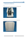
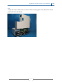
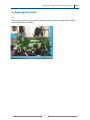
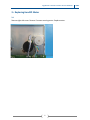
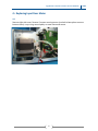
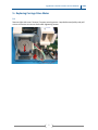
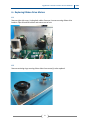
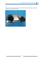
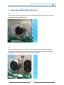
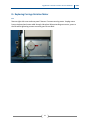
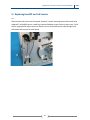
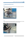
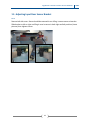
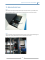
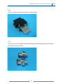
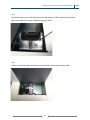
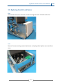
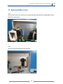
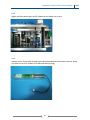
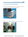
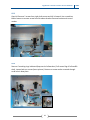
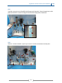
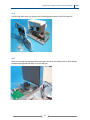
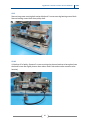
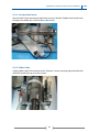
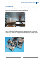
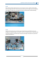
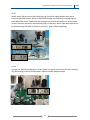
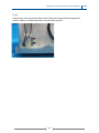
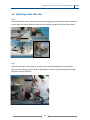
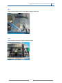
Service Manual for Signature Cassette Printer ©2015 All rights reserved Rear and Side Covers 02 Main Board 04 Headlift Motor 05 Input Door Motor 06 Carriage Drive Motor 07 Ribbon Drive Motors 08 Headlift & Ribbon Idler Gears 10 Carriage Rotation Motor 11 Headlift & Lid Sensors 12 Input Door Sensor 13 Input Door Sensor Bracket 14 Cassette Sensor 15 Cassette Load Sensor 18 Ribbon Sensor 19 Access Internal Sensors & Ribbon Cable 21 Carriage Home Sensor 26 Ribbon Cable 26 Carriage Rotation Sensor 27 Idler Post 31 Troubleshooting 35 ©2015 All rights reserved 1 Signature Cassette Printer Service Manual 1 ▪ Removing Rear and Side Covers 1.1 Open lid. Loosen 3 screws from the side or both sides that are being removed. 1.2 Remove rear panel. Loosen screw from side or both sides being removed. 2 2015 Signature Cassette Printer Service Manual 2015 1.3 Lift up side cover or both covers to remove. When removing right cover, disconnect control panel cable from main board. 3 Signature Cassette Printer Service Manual 2 ▪ Replacing Main Board 2.1 Remove right side cover. Disconnect all cables. Remove 4 screws securing board. Replace board and reconnect all cables. 4 2015 Signature Cassette Printer Service Manual 3 ▪ Replacing Headlift Motor 3.1 Remove right side cover. Remove 2 screws securing motor. Replace motor. 5 2015 Signature Cassette Printer Service Manual 2015 4 ▪ Replacing Input Door Motor 4.1 Remove right side cover. Remove 2 screws securing motor (use hole in baseplate to access bottom screw). Loop oring around pulley on new motor and secure. 6 Signature Cassette Printer Service Manual 2015 5 ▪ Replacing Carriage Drive Motor 5.1 Remove right side cover. Remove 2 screws securing motor. Loop belt around pulley and pull out on new motor to remove slack while tightening screws. 7 Signature Cassette Printer Service Manual 6 ▪ Replacing Ribbon Drive Motors 6.1 Remove right side cover. Unplug both cables. Remove 4 screws securing ribbon drive bracket. Open lid and lift bracket and motors out of unit. 6.2 Remove retaining rings securing ribbon hubs from motor(s) to be replaced. 8 2015 Signature Cassette Printer Service Manual 2015 6.3 Remove screws and replace motor(s). Resecure ribbon hubs with retaining rings. Replace bracket into unit and connect cables. 9 Signature Cassette Printer Service Manual 7 ▪ Replacing Headlift & Ribbon Idler Gears 7.1 Remove right side cover. Remove two screws securing headlift motor bracket (use hole in main board to access bottom screw). 7.2 Remove small retaining ring. Remove and replace one or both damaged gears. Replace retaining ring. Reattach motor bracket. Be sure teeth on motor gear line up evenly with plastic gear. Rotate with thumb to verify gears turn smoothly. 10 2015 Signature Cassette Printer Service Manual 2015 8 ▪ Replacing Carriage Rotation Motor 8.1 Remove right side cover and rear panel. Remove 2 screws securing motor. Unplug motor from main board and route cable through side plate. When attaching new motor, press to the left while tightening screws to ensure gears do not bind. 11 Signature Cassette Printer Service Manual 2015 9 ▪ Replacing Headlift and Lid Sensors 9.1 Remove both side covers and rear panel. Remove 2 screws securing sensor that needs to be replaced. For headlift sensor, rotate flag counterclockwise to gain access to top screw. For lid sensor, pop open lid to gain access to bottom screw. Route new sensor cable though both side plates and connect to main board. 12 Signature Cassette Printer Service Manual 2015 10 ▪ Replacing Input Door Sensor 10.1 Remove both side covers and main board. Remove 2 screws securing sensor and pull cable out of wire saddles and through unit. 10.2 Secure new sensor and route through wire saddles. Feed end of cable through left side plate and use a needlenose to reach into right side plate and pull cable though. 13 Signature Cassette Printer Service Manual 2015 11 ▪ Adjusting Input Door Sensor Bracket 11.1 Remove left side cover. Sensor should be centered in arc of flag. Loosen screws on bracket. Slide bracket to left or right until flag is even in sensor in both right and left positions (insert pictures) then tighten screws. 14 Signature Cassette Printer Service Manual 2015 12 ▪ Replacing Cassette Sensor 12.1 Slide cassette pivot block assembly fully forward and rotate clockwise. Use needlenose to unhook spring from block. Use allen wrench to loosen both set screws a few rotations. 12.2 Open lid and slide cassette pivot block assembly to center of unit. Pull pins and bearings out of both sides. Unplug ribbon cable from sensor and lift block out of unit. 15 Signature Cassette Printer Service Manual 2015 12.3 Remove 2 screws securing cassette sensor. Replace sensor. 12.4 Be sure pins have 0.01 washers between retaining rings and bearings (add them if the unit did not previously have them). 16 Signature Cassette Printer Service Manual 12.5 Set block back onto assembly and replace bearings and pins. Slide assembly fully forward again and retighten set screws. Reattach spring to block. 12.6 Rotate cassette pivot block assembly counterclockwise and reattach ribbon cable. 17 2015 Signature Cassette Printer Service Manual 2015 13 ▪ Replacing Cassette Load Sensor 13.1 Remove both side covers. Remove 4 screws securing front cover. Remove front cover. 13.2 Remove 2 screws securing cassette load sensor and unplug cable. Replace sensor and front cover. 18 Signature Cassette Printer Service Manual 2015 14 ▪ Replacing Ribbon Sensor 14.1 Remove both side covers. Remove screw and retaining ring indicated. Unplug ribbon sensor cable from main board. 14.2 Remove screws and retaining ring indicated. 19 Signature Cassette Printer Service Manual 2015 14.3 Slightly pull side panels apart and lift ribbon sensor bracket out of unit. 14.4 Replace sensor. Route cable through right side plate and place bracket back into unit, being sure tabs fit into slots. Replace all screws and retaining rings. 20 Signature Cassette Printer Service Manual 2015 15 ▪ Accessing Internal Sensors & Ribbon Cable 15.1 To replace carriage rotation sensor, carriage home sensor or ribbon cable, the left side plate needs to be removed. Remove both side covers. Remove front cover. 15.2 Remove headlift motor bracket from right side plate. Unhook spring from lid lift bracket. 21 Signature Cassette Printer Service Manual 2015 15.3 Open lid. Remove 2 screws from right shaft mount and tilt it forward. Use screwdriver behind mount to remove screw from lid release bracket. Remove bracket and curved washer. 15.4 Remove 5 retaining rings indicated (keep track of all washers). Pull sensor flag off of headlift shaft. Loosen both set screws (insert picture). Bottom set screw can be accessed through small hole in base plate. 22 Signature Cassette Printer Service Manual 2015 15.5 Use pliers to pry pin out of headlift shaft (keep track of washer). Access through slot in side plate and remove 2 screws securing belt tension block (keep track of washers). 15.6 Remove 7 screws indicated. Tip unit up to access 3 screws from bottom of base plate. 23 Signature Cassette Printer Service Manual 2015 15.7 Pull left side plate from unit. Keep track of bushing and washers as left link comes off. 15.8 Remove retaining ring indicated. Remove input cover from unit (keep track of white washer between bushing and side plate, as it may fall out). 24 Signature Cassette Printer Service Manual 2015 15.9 Remove long screw securing belt tension block and 2 screws securing bearing mount block. Remove bearing mount block from pulley shaft. 15.10 Lift belt up off of pulley. Remove 2 screws securing wire plenum bracket to base plate (note that both screws are slightly shorter than others used in unit and must be reused in same location). 25 Signature Cassette Printer Service Manual 15.11 – Carriage Home Sensor Remove both screws securing carriage home sensor to bracket. Replace sensor and route through wire saddles (be sure wire goes under shaft). 15.12 – Ribbon Cable Unplug ribbon cable from cassette sensor. Remove 2 screws securing capture bracket (tilt drive belt attachment up to access screws). 26 2015 Signature Cassette Printer Service Manual 2015 15.13 – Ribbon Cable Remove 2 screws securing capture bracket. Replace ribbon cable and secure in both capture brackets (be sure ribbon cable is level when tightening screws). After replacing wire plenum bracket verify ribbon cable is level and does not snag on bracket. 15.14 – Carriage Rotation Sensor Remove screw securing input brace bracket to right side plate (keep track of bearing and washers on pin). Remove both screws securing carriage rotation sensor to bracket. Replace sensor and route through wire saddles (be sure wire goes under shaft). Reattach bracket (be sure bearing on pin goes into hole on carriage). 27 Signature Cassette Printer Service Manual 2015 15.15 Reattach wire plenum bracket (be sure to use 2 shorter screws). Loop belt around pulley. Secure bearing mount block. Secure belt tension block (just start long screw, do not tighten). Place right pin of input cover into right link (make sure white washer is behind bushing). 15.16 Replace left side plate (be sure all shafts goes through bearings and lid lift bracket goes through slot on right side plate). Secure all 7 screws. Use channel lock pliers to press pin back into hole on lid shaft, so one end of pin is flush with flat edge of shaft (be sure to place thin washer onto shaft first). 28 Signature Cassette Printer Service Manual 2015 15.17 Attach sensor flag and secure with retaining ring. Secure lid release bracket then secure screws in right shaft mount. Route 4 cables back through unit. Replace 2 retaining rings on both ribbon idler shafts. Replace left link (arrange link, bushing and washers in order shown in insert pictures) and secure with retaining rings. If necessary, sensor input door bracket can be removed to get link back on (Refer to section 11, page 14 when replacing). 15.18 Arrange link, bushing and washers in order shown in insert picture and secure with retaining ring. Hook spring to end of lid lift bracket. Replace headlift stepper bracket. 29 Signature Cassette Printer Service Manual 15.19 Tighten long screw connected to belt tension block until carriage belt has appropriate tension. Replace 2 screws and washers to secure block in place. 30 2015 Signature Cassette Printer Service Manual 2015 16 ▪ Tightening Loose Idler Post 16.1 Remove both side covers. Remove bottom retaining ring on left link (keep track of washers). Loosen both set screws (bottom screw can be accessed through small hole in base plate). 16.2 Remove input door motor (bottom screw can be accessed through hole in base plate). Remove tiny retaining ring and slide off black pulley. Remove top retaining ring from right link (keep track of washers). 31 Signature Cassette Printer Service Manual 16.3 Slide link and shaft out until it stops against edge of base plate. 16.4 Remove both screws securing wire plenum bracket. 32 2015 Signature Cassette Printer Service Manual 2015 16.5 Remove bearing that shaft was in from left side plate. Slide long screwdriver into hole and lift wire plenum bracket slightly to access screw securing idler post. Tighten or replace screw (with Loctite 242) while gripping idler post with pliers. Be sure post is solid on side plate. Replace 2 screws in wire plenum bracket. Press bearing back into left side plate. 16.6 Arrange link, bushing and washers in order shown in insert picture and secure with retaining ring. Slide pulley onto post and secure with tiny retaining ring. Loop oring around both pulleys and secure input door motor. 33 Signature Cassette Printer Service Manual 16.7 Arrange link and washers in order shown in insert picture and secure with retaining ring. Tighten both set screws. 34 2015 Signature Cassette Printer Service Manual 17 ▪ Troubleshooting 17.1 X 35 2015