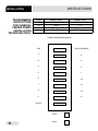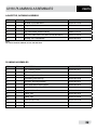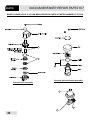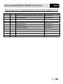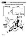
1
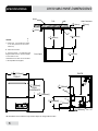
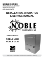
NOBLE SERIES
ELECTRICALLY HEATED
UNDERCOUNTER
DISHMACHINES
INSTALLATION, OPERATION
& SERVICE MANUAL
FOR NOBLE MODEL(S):
NOBLE UH30
NOBLE UL30
NOBLE UH30/UL30 Technical Manual • P/N 07610-004-25-09 • Issued 06-05-15 • Revised N/A
01
REVISION HISTORY
Revision
Letter
Revision Date
Made By
Applicable ECNs
A
06-04-15
KAP
N/A
Details
Release to production
i
NOMENCLATURE
NOBLE UH30
High temperature, hot water sanitizing, with a booster tank.
Detergent & rinse aid chemical feeder pumps.
NOBLE UL30
Low temperature, chemical sanitizing, no booster tank.
Detergent, rinse aid & sanitizer chemical feeder pumps.
Detergent & rinse aid chemical feeder pumps
Model:
Serial No.:
Installation Date:
Service Rep. Name:
Phone Number:
ii
TABLE OF CONTENTS
SPECIFICATIONS
NOBLE UH30 & UL30 DIMENSIONS....................................................................................................... 1
OPERATING PARAMETERS.................................................................................................................... 3
ELECTRICAL REQUIREMENTS.............................................................................................................. 4
INSTRUCTIONS
INSTALLATION......................................................................................................................................... 5
OPERATING........................................................................................................................................... 14
DELIME................................................................................................................................................... 16
MAINTENANCE
PREVENTATIVE MAINTENANCE.......................................................................................................... 17
TROUBLESHOOTING............................................................................................................................ 19
PARTS
CONTROL PANELS................................................................................................................................ 21
KICK PANEL WELDMENT...................................................................................................................... 24
TERMINAL BLOCK BOX ASSEMBLY..................................................................................................... 25
PERIPUMP TRACK ASSEMBLIES......................................................................................................... 26
CHEMICAL FEEDER PUMP ASSEMBLIES........................................................................................... 28
CHEMICAL FEEDER PUMP COMPONENTS........................................................................................ 30
PLUMBING ASSEMBLIES...................................................................................................................... 31
VACUUM BREAKER REPAIR PARTS KIT.............................................................................................. 33
WASH MANIFOLD ASSEMBLY.............................................................................................................. 35
MOTOR & PUMP ASSEMBLY................................................................................................................ 37
RINSE ARM & WASH ARM ASSEMBLIES............................................................................................. 39
UH30 THERMOSTAT & RINSE TANK ASSEMBLY................................................................................. 40
NOBLE UL30 OPTIONAL THERMOSTAT & HEATER COMPONENTS................................................ 41
DOOR ASSEMBLY.................................................................................................................................. 42
CLYDE SWITCH ARM............................................................................................................................. 44
MISCELLANEOUS DOOR COMPONENTS........................................................................................... 45
FRAME AND PANEL COMPONENTS.................................................................................................... 47
MISCELLANEOUS PARTS..................................................................................................................... 49
STANDS & COMPONENTS.................................................................................................................... 50
HTS-11 SCALE PREVENTION & CORROSION CONTROL DEVICE.................................................... 51
GO BOX KIT............................................................................................................................................ 52
VACUUM SWITCH ASSEMBLY.............................................................................................................. 53
VACUUM SWITCH ASSEMBLY INSTALLATION.................................................................................... 54
SCHEMATICS
NOBLE UH30 208-230 VOLT, 60 HERTZ, SINGLE PHASE................................................................... 55
NOBLE UH30 480 VOLT, 60 HERTZ, THREE PHASE........................................................................... 56
NOBLE UL30 115 VOLT, 60 HERTZ, SINGLE PHASE........................................................................... 57
iii
UH30 MACHINE DIMENSIONS
SPECIFICATIONS
WALL
B
TOP
GEND:
Water Inlet - 1/2" Female Pipe Thread,
2 1/2" AFF (Connect to a true 1/2" ID
water line)
LEGEND:
TOP Clearance B
Wall
Wall Clearance
A - Water
Inlet - 1/2" Female Pipe
Thread,
9
1 [6mm]
9
1
1 [40mm]
1 [40mm]
16 1/2" ID 4
4 [6mm]
16
2 1/2"
AFF (Connect to a true
1 [32mm]
14
water line)
1 [32mm]
14
m]
Electrical Connection
A
Drain Connection - 10' coiled drain hose.
LEGEND:
pped inside machine.
Must be installed
233
4 [604mm]
more thanA 24"
AFF.
- Water Inlet - 1/2" Female Pipe Thread,
2 1/2" AFF (Connect to a true 1/2" ID
water line)
dimensions from
floor can be increased
with adjustable
feet supplied.
B - Electrical Connection
Open
WALL
WALL
1 [32mm]
14
Door Open
All dimensions from floor can be increased
1" with adjustable feet supplied.
165 [423mm]
8
Door Open
BACK
All dimensions from floor can be increased
A
1" with adjustable feet 3supplied.
233
4 [604mm]
24 3 [615mm]
16
FRONT
BACK
5 [84mm]
316
A
1 [292mm]
12
7 [22mm]
8
111 [292mm]
2
Door Op
165 [423mm]
8
1412" [368mm]
DISH
CLEARANCE
BACK
33 5 [846mm]
16
316 [84mm]
33 5 [846mm]
16
B
33 5 [846mm]
16
A
7 [22mm]
8
165 [423mm]
8
1412" [368mm]
DISH
CLEARANCE
5
1412" [368mm]
DISH
CLEARANCE
B
258 [644mm]
24 3 [615mm]
16
FRONT
5 [84mm]
316
B
253 [644mm]
3
8 drain hose.
C -23
Drain
Connection
- 10' coiled
4 [604mm]
B
TOP
Wall Clearance
[644mm]
253
Shipped inside machine.
Must be1 [6mm]
installed
8
1 9 [40mm]
4
16
no more than 24" AFF.
C - Drain Connection - 10' coiled drain hose.
Shipped inside machine. Must be installed
no more than 24" AFF.
24 3 [615mm]
16
FRONT
B - Electrical Connection A
41 [105mm]
8 41 [105mm]
8
C
C
A
1
112 [292mm] 7
[22mm]
8
41 [105mm]
8
*All dimensions are for reference only and are subject to change without notice.
1
C
UL30 MACHINE DIMENSIONS
B
TOP
END:
ater Inlet - 1/2" Female Pipe Thread,
1/2" AFF (Connect to a true 1/2" ID
ater line)
m]
B
TOP
Wall Clearance
Wall Clearance
1 [6mm]
9
A - Water Inlet
- 1/2" Female Pipe1Thread,
[40mm]
9
1
4
16
1 [40mm]
2 1/2" AFF
(Connect to a true 1/2" ID
4 [6mm]
16
water
line)
11
4 [32mm]
11
[32mm]
4
B - Electrical Connection
A
rain Connection - 10' coiled drain hose.
LEGEND: Must be installed
ed inside machine.
3
ore than 24" AFF.234 [604mm]
WALL
mensions
h adjustable feet supplied.
11
4 [32mm]
B - Electrical Connection
C - Drain Connection - 10' coiled drain hose.
Shipped inside machine. Must be installed
no more than 24" AFF.
All dimensions from floor can be increased
1" with adjustable feet supplied.
3 [604mm]
253 [644mm]
23
8
C - Drain4Connection - 10' coiled drain
hose.
All dimensions from floor can be increased
A
1" with adjustable feet supplied.
165 [423mm]
8
1 [89mm]
32
B
A
1 [292mm]
112
16 [423mm]
8
Door Ope
3 [615mm]
2416
BACK
1 [89mm]
FRONT
32
B
253
8 [644mm]
5
233
4 [604mm]
Door Open
Door Open
3 [615mm]
2416
A
B
TOP
Wall Clearance
3
Shipped inside machine. Must
be installed
25 [644mm]
9 [40mm]
1
8
116
4 [6mm]
no more than 24" AFF.
A - Water Inlet - 1/2" Female Pipe Thread,
2 1/2" AFF (Connect to a true 1/2" ID
fromwater
floorline)
can be increased
1 [292mm]
12
WALL
LEGEND:
WALL
ectrical Connection
Open
SPECIFICATIONS
165
8 [423mm]
FRONT
3 [615mm]
2416
BACK
FRONT
1312" [343mm]
DISH
1CLEARANCE
5 [110mm]
416
5
416 [110mm]
C
33 5 [846mm]
16
C
BACK
5 [846mm]
3316
32 [89mm]
5 [846mm]
3316
B
1312" [343mm]
DISH
CLEARANCE
A
1312" [343mm]
DISH
CLEARANCE
111 [292mm]
2
A
C
4 5 [110mm]
16
*All dimensions are for reference only and are subject to change without notice.
2
OPERATING PARAMETERS
SPECIFICATIONS
Model Designation:
Operating Capacity:
NOBLE UH30
NOBLE UL30
Racks per Hour
24
24
Dishes per Hour
600
600
Glasses per Hour
864
864
Wash Tank
1.1
1.2
Rinse Tank
1.1
3.0
Wash Motor HP
0.75
0.75
Rinse Heater KW
8.2
N/A
Tank Capacity (Gallons):
Electrical Loads (as applicable):
NOTE: Always refer to the machine data plate for specific electrical and water requirements.
The material provided on this page is for reference only and is subject to change without notice.
HOT WATER SANITIZING
Water Temperatures (Fahrenheit):
Minimum Wash Temperature
150
N/A
Minimum Rinse Temperature
180
N/A
Minimum Incoming Water Temperature
110
N/A
N/A
120
Minimum Rinse Temperature
N/A
120
Minimum Incoming Water Temperature
N/A
120
Water Flow Pressure (PSIG)
20
20
Flow Rate Minimum (GPM)
0.44
0.48
1/2"
1/2"
1-3/8"
1/2"
Chemical Sanitizing:
Water Temperatures (Fahrenheit):
Minimum Wash Temperature
Other Water Requirements:
Water Line Size (NPT)
Drain Line Size (NPT)
Minimum Chlorine Required (PPM)
3
N/A
50
ELECTRICAL REQUIREMENTS
All electrical ratings provided in this manual are for reference only.
Always refer to the machine data plate to get the exact electrical
information for your machine. All electrical work performed on
machines should be done in accordance with applicable local,
state, territorial and national codes. Work should only be performed
by qualified electricians and authorized service agents.
Note that all electrical wiring used in the NOBLE UH/UL30 series
of machines must be rated, at a minimum, for 100◦C (212◦F).
Furthermore, use copper conductors only.
Where applicable, heating element amperage draws have been
adjusted for the assumed input voltage. Noble assumes incoming
voltages will be either 208, 230 or 460 volts. Some of the heating
elements used in our machines are actually rated for other
voltages, such as 240 or 480 volts. Always verify the amperage
draw of the machine in operation when sizing circuit protection.
If your machine is equipped with the optional rinse heater, note
the rinse heater has its own electrical connection and therefore
requires a separate service. Amperage loads for motors and
heaters are called out on the machine data plate for the installation/
service technician.
The electrical configurations of the NOBLE UH/UL30 series of
machines are as follows:
Available Electrical Characteristics:
• 115 volt, 60 Hz, single phase
• 208 volt, 60 Hz, single phase
• 230 volt, 60 Hz, single phase
• 460 volt, 60 Hz, three phase
SPECIFICATIONS
NOBLE UH30
Electrical Characteristics
VOLTS
208
230
460
PHASE
1
1
3
FREQ
60
60
60
WASH MOTOR
AMPS
6.6 A
6.6 A
1.3A
RINSE HEATER
32.2 A 35.7 A 42.3 A
AMPS
FLA
38.8 A 42.3 A
13.3
NOBLE UL30
Electrical Characteristics
VOLTS
15
PHASE
1
FREQ
60
WASH MOTOR
AMPS
13.2 A
RINSE HEATER
AMPS
N/A
FLA
13.2
Available Wash Tank Heaters:
• 8.2KW (standard for NOBLE UH30)
4
INSTALLATION
VISUAL INSPECTION:
DO NOT THROW AWAY
CONTAINER IF DAMAGE
IS EVIDENT
INSTRUCTIONS
Before installing the unit, check the container and the machine for damage. A damaged container may be an indication there is possible damage to the machine. If there
is any type of damage to both the container and the unit, DO NOT THROW AWAY
THE CONTAINER. The dish-machine has been previously inspected at the factory
and is expected to arrive to you in new, undamaged condition. However, rough handling by carriers or others may result in damage to the unit while it is in transit. If such
a situation occurs, DO NOT RETURN THE UNIT TO NOBLE. Instead, contact the
carrier and ask them to send a representative to the site to inspect the damage. You
should request that an inspection report be completed. You must contact the carrier
within 48 hours of receiving the machine in order to report possible freight damage.
You are also encouraged to contact the dealer through which you purchased the unit.
UNPACKING THE
MACHINE:
The machine should be unboxed and/or removed from the pallet prior to installing.
Open the front door and remove all of the materials from the inside. Once unpacked,
verify there are no missing parts to the best of your ability. If you discover a part is
missing, contact Noble immediately.
LEVEL THE
DISHMACHINE:
The dish-machine is designed to operate while level. This is important to prevent any
damage to the machine during operation and to ensure the best results possible. The
unit comes equipped with adjustable feet, which can be turned using a pair of channel
locks or by hand. Verify the unit is level from front to back and side to side prior to
making any electrical or plumbing connections.
PLUMBING THE
DISHMACHINE:
All plumbing connections must be made to adhere to local, state, territorial and national codes. The installing plumber is responsible for ensuring the incoming water
lines are flushed of debris prior to connecting to the machine. Note that chips and
materials from cutting processes can become lodged in the solenoid valves and prevent them from opening or closing. Any valves that are found to be fouled or defective
because of foreign matter left in the water line, and any subsequent water damage,
are not the responsibility of the manufacturer.
A water hardness test
must be performed.
A water hardness test must be performed to determine if the HTS-11 (scale prevention & corrosion control) need to be installed. A hardness test kit is attached to the
warning tag that is attached to the incoming plumbing connection on the back of the
machine. If the hardness is higher than 5 GPG the HTS-11 will need to be installed.
Please contact Noble immediately to have this shipped to you.
5
INSTRUCTIONS
INSTALLATION
WATER SUPPLY
CONNECTIONS:
WATER HARDNESS
GREATER THAN
5 GPG
Ensure you have reads the above section entitled “PLUMBING THE MACHINE” above
before proceeding. Install the HTS-11 into the water line (1/2” ID pipe size minimum)
before the dish machine line incoming water connection point using copper pipe. The
HTS-11 must be installed vertically. A mounting bracket is provided to facilitate the
venture metering head to the wall. Observe proper inlet/outlet water directions. Flow
directions are molded into the top of the head. It is recommended that a water shut
off valve be installed before the HTS-11 to allow access for servicing. Plumb from the
HTS-11 outlet to the incoming water connection point using copper pipe (or order the
1/2” ID flexible hose kit offered by Noble). The water supply is to be capable of 20 PSI
(plus or minus 5 PSI) “flow” pressure at the recommended temperature indicated on
the data plate. See “Shock Absorber” section.
WATER SUPPLY
CONNECTION:
WATER HARDNESS
OF 5 GPG OR LESS
Ensure you have read the section entitled “PLUMBING THE DISH MACHINE” before
proceeding. Install the water supply line (1/2” ID pipe size minimum) to the dish machine incoming water connection point using copper pipe (or order the 1/2” ID flexible
hose kit offered by Noble). It is recommended that a water shut off valve be installed in
the water line between the main supply and the machine to allow access for service.
The water supply line is to be capable of 20 PSI (plus or minus 5 PSI) “flow” pressure
at the recommended temperature indicated on the data plate.
CHEMICAL
CONNECTIONS:
Upon first installation, the chemical alarm will buzz until the chemical feeder pumps
are primed. If the chemicals run out, the chemical alarm will buzz until the chemical
is replaced and primed if necessary. The bottom of the chemical container cannot be
located any higher than 8” from the floor. If the unit is shipped with a 6” or 18” table
stand, then the highest position will be respectively 14” or 26” from the floor.
PRESSURE
REGULATOR:
Noble offers a water pressure regulator that can be purchased separately. Regulators
help areas where the water pressure fluctuates or is lower than the recommended
pressure. DO NOT confuse STATIC pressure with FLOW pressure. Static pressure
is the line pressure in a “no flow” condition (all valves and services are closed). Flow
pressure is the pressure in the fill line when the valve is opened during the cycle.
SHOCK ABSORBER:
Also, it is suggested that a shock absorber (NOT SUPPLIED) be installed on the
incoming water line. This prevents water hammer (hydraulic shock), induced by the
solenoid valve as it operates, from causing damage to the equipment.
Take care not to confuse
static pressure with
flow pressure.
6
INSTALLATION
INSTRUCTIONS
CONNECTING THE
DRAIN LINE:
The dish machine has a pumped (pressure) drain capable of pumping waste water
to a height of 24” above the floor to the kitchens drain system. Each dish machine is
supplied with a six foot long hose. This ships INSIDE the unit. When installed, it will
extend from the rear side of the machine. There also must be an air gap between the
machine drain line and the floor sink or drain. If a grease trap is required by code, it
should have a flow capacity of 12 GPM (Gallons Per Minute).
PLUMBING CHECK:
Slowly turn on the water supply to the machine after the incoming fill line and the drain
line have been installed. Check for any leaks and repair as required. All leaks must be
repaired prior to placing the machine into operation.
ELECTRICAL POWER
CONNECTIONS:
Electrical and grounding conductors must comply with the applicable potions of the
National Electric Code ANSI/NFPA 70 (latest edition) and/or other electrical codes.
DISCONNECT ELECTRICAL
POWER SUPPLIES & TAG
OUT IN ACCORDANCE
WITH APPROPRIATE
PROCEDURES & CODES
AT THE DISCONNECT
SWITCH TO INDICATE
THE CIRCUIT IS BEING
SERVICED.
The data plate is located toward the right front side of the dish machine. Refer to the
data plate for machine operating requirements, machine voltage, total amperage &
serial number.
To install the incoming power lines, remove the back panel. This will require taking
a Phillips head screw driver and removing the two screws at the bottom of the back
panel; remove the back panel and set aside. Install 3/4” conduit into the pre-punched
holes in the back of the control box. Route power wires and connect to power block
and grounding lug. Install the service wires (L1 and L2) to the appropriate terminals as
they are marked on the terminal block. Install the grounding wire into the lug provided.
It is recommended that “DE-OX” or another similar anti-oxidation agent be used on
all power connections.
VOLTAGE CHECK:
Ensure that the power switch is in the OFF position and apply power to the dish
machine. Check the incoming power at the terminal block and ensure it corresponds
with the voltage listed on the data plate. If not, contact a qualified service agency to
examine the problem. Do not run the dish machine if the voltage is too high or too
low. Shut off the service breaker and mark it as being for the dish machine. Advise all
proper personnel of any problems and of the location of the service breaker. Replace
the control box cover and tighten down the screws.
SURROUNDING
AREA:
This is a commercial dish machine and reaches temperatures that can exceed
those generated by a residential machine. Therefore, any surrounding countertops,
cabinets, flooring material & sub floor material must be designed and/or selected with
these higher temperatures in mind.
Note: any damage to surrounding area that is caused by heat and or moisture
to materials selected that are NOT recommended for higher temperatures will
not be covered under warranty or by Noble Warewashing.
7
INSTRUCTIONS
INSTALLATION
THERMOSTATS:
The thermostats on your NOBLE UH/UL30 unit have been set at the factory. They
should only be adjusted by an authorized service agent.
CHEMICAL FEEDER
EQUIPMENT:
This equipment is not recommended for use with deionized water or other aggressive
fluids. Use of deionized water or other aggressive fluids will result or corrosion and
failure of materials and components. Use of deionized water or other aggressive fluids
will void the manufacturers warranty.
NOTE: The bottom of the chemical container cannot be located any higher than 8”
from the floor. If the unit is equipped with the 6” or 18” table stand, then the highest
position will respectively be 14” or 26” from the floor. this, contact Noble immediately
for assistance.
It is important to remember that if you decide to operate the unit in chemical sanitizing
mode, you must ensure an appropriate chlorine-based sanitizer is used in the final
rinse line.
WARNING! CHLORINE BASED SANITIZERS CAN BE DETRIMENTAL TO YOUR
MACHINE IF THE CHEMICAL SOLUTION IS TOO STRONG. SEE YOUR CHEMICAL
PROFESSIONAL TO ENSURE YOUR DISPENSER IS SET UP CORRECTLY.
TO PREPARE
CHEMICAL
FEEDER PUMPS
FOR OPERATION:
The NOBLE UH30 dish machine is supplied with integral detergent and rinse aid
chemical feeder pumps. The NOBLE UL30 dish machine is supplied with integral
detergent, rinse additive, and sanitizer chemical feeder pumps. Locate the open ends
of the chemical tubes with the tube stiffeners and place each one in the appropriate
container.
A. Red Tubing=Detergent
B. Blue Tubing= Rinse Aid
C. White Tubing= Sanitizer
PRIMING CHEMICAL
FEEDER PUMPS:
Chemical feeder pumps need priming when the machine is first installed or if for some
reason, the chemical lines have been removed and air is allowed to enter.
CAUTION! Water must be in the sump and wash tank prior to the dispensing of
chemicals. Sanitizer in concentration is caustic and may cause damage without
dilution.
8
INSTALLATION
PRIMING CHEMICAL
FEEDER PUMPS
(CONTINUED):
INSTRUCTIONS
1. Verify that the proper chemical tube stiffener inlet is in the proper container.
2. Use the prime switches located on the control panel at the bottom of the unit to
prime each pump. The switches are clearly marked as to what chemical feeder
pump they are assigned to.
3. To prime the pumps, hold the switch in the momentary position until chemical
can be observed entering the pump.
4. Detergent is dispensed as required during the wash cycle by the timer. The
amount of detergent may need to be increased or decreased depending upon
water quality and type of detergent.
5. Rinse additive is dispensed as required into the final rinse. The amount of rinse
additive may need to be adjusted depending upon water hardness & results.
6. Sanitizer (either chlorine or iodine) is dispensed into the final rinse. The amount
of sanitizer may need to be adjusted depending on the concentration and type
of sanitizer used.
7. Please refer to the next page for instruction on adjusting the chemical feeder
pumps on the universal timer.
WARNING: Some of the chemicals used in dish washing may cause chemical
burns if they come in contact with your skin. Wear protective gear when handling these chemicals. If you do come in contact with these chemicals, immediately follow the instructions provided with the chemicals for treatment.
9
INSTRUCTIONS
PROGRAMMING
INSTRUCTIONS
FOR CHEMICAL
FEEDER PUMPS
(INSTALLATION
TECHNICIAN ONLY):
INSTALLATION
To access the programming mode, the machine must be ON and idle (between
cycles).
On the timer board, press and hold both the MOVE and ENTER buttons on the
timer board simultaneously for two seconds.
The PROGRAM (PGM) light and light A will illuminate.
NOTE: Once in the programming mode, the MOVE button is used to scroll
between the programming categories and the ENTER button is used to select
the category.
Press the MOVE button to move the solid light to the desired location of FILL,
RINSE AID, DETERGENT, or SANITIZER. Please note that options A, B, C and
D are not adjustable outputs.
Press the ENTER button for the chosen category. Now, the (PGM) light will
illuminate along with lights corresponding to the time values for the chosen
category. The ACCEPT light will blink.
The PROGRAM light will illuminate.
To change the value of a parameter, use the MOVE button to illuminate the
light next to the time option (time is measured in seconds). In the time categories, each second in use will light up. To deselect the option, press ENTER
and the light will go off, press ENTER again and it will illuminate. Once you
have set your time catergory, press the MOVE button until the ACCEPT light
illuminates and press ENTER. This will save the changed parameters.
Once you press the ENTER button when the ACCEPT light is blinking you will
exit the programming mode. To change any other values, you will have to return to the programming mode. To revert back to a previous setting, you must
return to that option and change the parameter back to the previous setting.
Once in the programming mode, if there have been no keypad inputs for
approximately two minutes, the system will automatically exit out of the programming mode. Any changes to parameters will be saved when the programming mode is automatically exited.
The wash and drain cycles are not adjustable.
All time adjustments are in seconds. Refer to the chart on the following page
for adjustable outputs.
10
INSTRUCTIONS
INSTALLATION
PROGRAMMING
INSTRUCTIONS
FOR CHEMICAL
FEEDER PUMPS
(INSTALLATION
TECHNICIAN ONLY):
PGM
NOBLE UH30
NOBLE UL30
E
F
G
H
Not Adjustable
Rinse
Detergent
Rinse Aid
Rinse Aid
Fill
Sanitizer
Detergent
TIMER PROGRAMMING BOARD
PGM
TIME IN SECONDS
A
8
B
4
C
2
D
1
E
0.8
F
0.4
G
0.2
H
0.1
ACCEPT
MOVE
11
ENTER
INSTRUCTIONS
DETERGENT
CONTROL:
INSTALLATION
Detergent usage and water hardness are two factors that contribute greatly to how
efficiently your dish machine will operate. Using detergent in the proper amount
can become, in time, a source of substantial savings. A qualified water treatment
specialist can tell you what is needed for maximum efficiency from your detergent, but
you should still know some basics so you’ll understand what they are talking about.
First, you must understand that hard water greatly effects the performance of the dish
machine. Water hardness is the amount of dissolved calcium and magnesium in the
water supply. The more dissolved solids in the water, the greater the water hardness.
Hard water works against detergent, thereby causing the amount of detergent required
for washing to increase. As you use more detergent, your costs for operating the dish
machine will increase and the results will decrease. The solids in hard water also
may build-up as a scale on wash and rinse heaters, decreasing their ability to heat
water. Water temperature is important in removing soil and sanitizing dishes. If the
water cannot get hot enough, your results may not be satisfactory. This is why Noble
recommends that if you have installed the machine in an area with hard water, that
you also install some type of water treatment equipment to help remove the dissolved
solids from the water before it gets to the dish machine.
Second, hard water may have you adding drying agents to your operating cycle to
prevent spotting, when the real problem is deposited solids on your ware. As the water
evaporates off of the ware, the solids will be left behind to form the spotting and no
amount of drying agent will prevent this. Again, using treated water will undoubtedly
reduce the occurrences of this problem.
Third, treated water may not be suitable for use in other areas of your operation. For
instance, coffee made with soft water may have an acid or bitter flavor. It may only be
feasible to install a small treatment unit for the water going into the dish machine itself.
Discuss this option with your qualified water treatment specialist.
Even after the water hardness problems have been solved, there still must be proper
training of dish machine operators in how much detergent is to be used per cycle.
Talk with your water treatment specialist and detergent vendor and come up with a
complete training program for operators. Using too much detergent has as detrimental
effects as using too little. The proper amount of detergent must be used for job. It is
important to remember that certain menu items may require extra detergent by their
nature and personnel need to be made aware of this. Experience in using the dish
machine under a variety of conditions, along with good training in the operation of
the machine, can go a long way in ensuring your dish machine operates as efficiently
as possible.
Certain dish machine models require that chemicals be provided for proper operation
and sanitization. Some models even require the installation of third-party chemical
feeders to introduce those chemicals to the machine. Noble does not recommend or
endorse any brand name of chemicals or chemical dispensing equipment. Contact
your local chemical distributor for questions concerning these subjects.
Some dish machines come equipped with integral solid detergent dispensers. These
dispensers are designed to accommodate detergents in a certain sized container. If
you have such a unit, remember to explain this to your chemical distributor upon first
contacting them.
12
INSTALLATION
DETERGENT
CONTROL
(CONTINUED):
INSTRUCTIONS
As explained before, water temperature is an important factor in ensuring that your
dish machine functions properly. The data plate located on each unit details what the
minimum temperatures must be for either the incoming water supply, the wash tank
and the rinse tank, depending on what model of dish machine you have installed.
These temperatures may also be followed by temperatures that Noble recommends
to ensure the highest performance from you dish machine. However, if the minimum
requirements are not met, the chances are your dishes will not be clean or sanitized.
Remember, a dish can look clean, but it may not be sanitized. Instruct your dish
machine operators to observe the required temperatures and to report when they
fall below the minimum allowed. A loss of temperature can indicate a much larger
problem such as a failed heater or it could also indicate that the hot water heater for
your operation is not up to capacity and a larger one may need to be installed.
There are several factors to consider when installing your dish machine to ensure that
you get the best possible results from itand that it operates at peak efficiency for many
years. Discuss your concerns with your local chemical distributor and water treatment
specialist before there is a problem.
13
OPERATING INSTRUCTIONS
PREPARATION:
POWER UP:
FILLING THE
WASH TUB:
INSTALLATION
Before proceeding with the start-up of the unit, verify the following:
1. The strainer is in place and is clean.
2. That the wash and rinse arms are screwed securely into place and that their end
caps are tight. The wash and rinse arms should rotate freely.
3. Verify all chemical levels for machine chemical feeder pumps are correct.
To energize the unit, turn on the power at the service breaker. The voltage should
have been previously verified as being correct. If not, the voltage will have to be
verified.
For the initial fill, close the door and ensure that the MANUAL switch light is not on.
Depress and hold the START CYCLE switch until the auto light comes on and then
release the button. For the initial fill, run the machine through 3 cycles to fill the tub
sump. The machine will run a partial cycle and fill to the bottom of the pan strainer.
Open the door and verify that the water level is correct.
NOTE: For the NOBLE UH30:
Ensure the orange/white wires at the heater contactor are connected properly. They
have been purposely disconnected at the factory to avoid damage to the heater
element when there is no water in the booster heater.
Hereafter, the water level is controlled by the timer that has been preset at the
factory. Verify that there are no other leaks on the unit before proceeding any
further. The wash sump must be completely filled before operating the wash pump
to prevent damage to the component. Once the wash tub is filled, the unit is ready
for operation.
The machine runs a complete cycle to drain and fill. If the machine is not allowed to
drain, the water will build up inside the tub. After the initial fill, the rinse water for the
current cycle will become the wash water for the next cycle.
WARE
PREPARATION:
Proper preparation of ware will help ensure good results and less re-washes. If
not done properly, ware may not come out clean and the efficiency of the dish
machine will be reduced. It is important to remember that a dish machine is not
a garbage disposal and that simply throwing un scraped dishes into the machine
simply defeats the purpose altogether of washing the ware. Scraps should be
removed from ware prior to being loaded into a rack. Pre-rinsing and pre-soaking
are good ideas, especially for silverware and casserole dishes. Place cups and
glasses upside down in racks so that they do not hold water during the cycle. The
dish machine is meant not only to clean, but to sanitize as well, to destroy all of the
bacteria that could be harmful to human beings. In order to do this, ware must be
properly prepared prior to being placed in the machine.
14
INSTALLATION
DAILY MACHINE
PREPARATION:
WARM-UP CYCLES:
OPERATING INSTRUCTIONS
Refer to the section entitled “PREPARATION” at the top of this page and follow the
instructions there. Afterwards, check that all of the chemical levels are correct and/or
that there is plenty of detergent available for the expected workload.
For a typical daily start-up, it is recommended to run the machine through 3 cycles
to ensure that all of the cold water is out of the system and to verify that the unit is
operating correctly. To cycle the machine, ensure that the power is on and that the
tub has filled to the correct level.
Push the START CYCLE button and hold until the green cycle light is on and then
release, the unit will start, run through the cycle, and shut off automatically. Repeat
this two more times. The unit should now be ready to proceed with the washing of
ware.
WASHING A RACK
OF WARE:
To wash a rack, open the door completely and slide the rack into the unit. Close the
door, press the START CYCLE button and hold until the green cycle light is on and
release, the unit will start. Once the cycle is completed, open the door and remove
the rack of clean ware. Replace with a rack of soiled ware and close the door. The
process will then repeat itself.
OPERATIONAL
INSPECTION:
Based upon usage, the pan strainer may become clogged with soil and debris as
the workday progresses. Operators should regularly inspect the pan strainer to
ensure it has not become clogged. If the strainer does, it will reduce the washing
capability of the machine. Instruct operators to clean out the pan strainer at regular
intervals or as required by work load.
SHUTDOWN AND
CLEANING:
15
At the end of the workday, close the door. Start a cycle. Wait approximately five
seconds after the green cycle light comes on and then push the POWER OFF
switch. This will put the machine in shutdown mode which will let the machine drain
completely prior to shutting off. Once the wash tub is drained and power light is off,
remove he pan strainer. Remove soil and debris from the strainer and set to the
side. Unscrew the wash and rinse arms from their manifolds. Remove the end caps
and flush the arms with water. Use a brush to clean out the inside of the arms. If the
nozzles appear to be clogged, use a toothpick to remove the obstruction. Wipe the
inside of the unit out, removing all soil and scraps. Reassemble the wash and rinse
arms and replace them in the unit. The arms only need to be hand tight, do not use
tools to tighten them down. Reinstall the strainer and close the door.
OPERATING INSTRUCTIONS
DELIMING
OPERATIONS
INSTALLATION
In order to maintain the dish machine at its optimum performance level, it will be
required to remove lime and corrosion deposits on a frequent basis. A deliming solution should be available from your detergent supplier. Read and follow all instructions on the label of the deliming solution.
NOTE: If this machine is equipped with a HTS-11, scale prevention and corrosion
control device, and lime is becoming a frequent problem, the cartridge needs to
be replaced. To order a replacement cartridge, call Noble immediately to have one
shipped to you.
To proceed with the deliming operation, fill the dish machine and add the correct
amount of deliming solution as recommended by the deliming solution manufacturer.
The water capacity of the tank can be verified on the specification sheet (s) of this
manual.
Perform the following operations to delime the dish machine:
1. Push Manual Switch on the front of the control panel.
2. Close the door (after adding the deliming solution).
3. Run the machine for the recommended period of time.
4. Press the Power Switch to turn the unit off and open the door.
5. Wait five minutes, then inspect the inside of the machine. If the machine is not delimed, run another time cycle as per the deliming solution’s instructions.
6. When clean, drain and re-fill the machine.
7. Run in MANUAL for 10 minutes to remove residual deliming solution.
8. Drain and re-fill the machine.
16
MAINTENANCE
PREVENTATIVE
MAINTENANCE:
PREVENTATIVE MAINTENANCE
The dish machines covered in this manual are designed to operate with a minimum
of interaction with the operator. However, this does not mean that some items
will not wear out in time. Noble highly recommends that any maintenance and
repairs not specifically discussed in this manual should be performed by QUALIFIED SERVICE PERSONNEL ONLY. Performing maintenance on your dish
machine may void your warranty if it is still in effect.
There are many things that operators can do to prevent catastrophic damage to
the dish machine. One of the major causes of component failure has to do with
pre-scrapping procedures. A dish machine is not a garbage disposal; any large
pieces of material that are put into the machine shall remain in the machine
until they are either broken up (after spreading out on your ware!) or physically
removed. Strainers are installed to help catch debris, but they do no good if they
are clogged. Have operators regularly inspect the pan strainers to ensure (1) that
they are free of soil and debris and (2) they are laying flat in the tub.
When cleaning out strainers, do NOT beat them on waste cans. The strainers are
made of metal and can be forgiving; but once severe damage is done, it is next
to impossible for the strainer to work in the way it was designed to. Wipe out
strainers with a rag and rinse under a faucet if necessary. For stubborn debris,
a toothpick should be able to dislodge any obstructions from the perforations.
Always ensure that strainers are placed back in the machine before operation
and that they lay flat in the tub.
You may wish to also refer to the page entitled “Detergent Control” in order to learn
more about how your water hardness will effect the performance of your machine. Hard water makes dish machines work harder and decreases efficiency.
Again, it is important to remind operators that trying to perform corrective maintenance on the dish machine could lead to larger problems or even cause harm to
the operator. If a problem is discovered; secure the dish machine using proper
shut down procedures as listed in this manual and contact a QUALIFIED SERVICE AGENCY.
Some problems, however, may having nothing to do with the machine itself and no
amount of preventative
maintenance is going to help. A common problem has to do with temperatures
being too low. Verify that the water temperatures coming to your dish machine
match the requirements listed on the machine data plate. There can be a variety
of reasons why your water temperature could be too low and you should discuss
it with a QUALIFIED SERVICE AGENCY to determine what can be done.
17
By following the operating and cleaning instructions in this manual, you should get
the most efficient results from our machine. As a reminder, here are some steps
to take to ensure that you are using the dish machine the way it was designed to
work:
PREVENTATIVE MAINTENANCE
PREVENTATIVE
MAINTENANCE
(CONTINUED):
MAINTENANCE
1. Ensure that the water temperatures match those listed on the machine data
plate.
2. Ensure that all strainers are in place before operating the machine.
3. Ensure that all wash and/or rinse arms are secure in the machine before
operating.
4. Ensure that drains are closed/sealed before operating.
5. Remove as much soil from dishes by hand as possible before loading into racks.
6. Do not overfill racks.
7. Ensure that glasses are placed upside down in the rack.
8. Ensure that all chemicals being injected to machine have been verified as being
at the correct concentrations.
9. Clean out the machine at the end of every workday as per the instructions in the
manual.
10. Always contact a QUALIFIED SERVICE AGENCY whenever a serious problem
arises.
11. Follow all safety procedures, whether listed in this manual or put forth by local,
state or national codes/regulations.
18
TROUBLESHOOTING COMMON PROBLEMS
MAINTENANCE
WARNING:
Inspection, testing and repair of electrical equipment should be performed only by
qualified service personnel. Certain procedures in this section require electrical tests
or measurements while power is applied to the machine.
EXERCISE EXTREME CAUTION AT ALL TIMES.
If test points are not easily accessible, disconnect power, attach test equipment and
reapply power to test. When replacing electrical parts, disconnect power at source
circuit breaker.
PROBLEM
POSSIBLE CAUSE
REMEDY
Water overflow from
bottom of door.
1. Clogged drain.
1. Remove obstruction.
2. Machine not level.
2. Level machine, or increase height to the front.
3. Excessive inlet pressure.
3. Install pressure reducing valve, or adjust if
one is present. Ensure flow is 20 ±5 PSI.
4. Detergent foaming
4. Reduce detergent quantity.
Wash motor doesn’t operate on manual wash.
1.Loose or broken wires.
1. Reconnect or replace wires in motor.
2.Defective manual wash switch
2. Replace.
3.Defective motor starting relay.
3. Replace.
Motor operates on manual 1. Defective circuit in manual wash
wash but not on automat- switch.
ic.
1. Replace switch.
No water comes through
the rinse arms when the
“ON/FILL” switch is depressed.
1. Water not turned on.
1. Turn water on.
2. Defective solenoid valve.
2.Replace solenoid valve.
Little or no water coming
through the rinse assemblies.
1. Limed up rinse heads or piping.
1. Delime rinse heads.
2. Low water pressure.
2. Increase pipe size to machine. Adjust pressure regulator.
19
TROUBLESHOOTING COMMON PROBLEMS
WARNING:
MAINTENANCE
Inspection, testing and repair of electrical equipment should be performed only by
qualified service personnel. Certain procedures in this section require electrical tests
or measurements while power is applied to the machine.
EXERCISE EXTREME CAUTION AT ALL TIMES.
If test points are not easily accessible, disconnect power, attach test equipment and
reapply power to test. When replacing electrical parts, disconnect power at source
circuit breaker.
PROBLEM
POSSIBLE CAUSE
REMEDY
Rinse water runs continuously with breaker
turned off.
1. Defective plunger in solenoid valve.
1. Delime rinse heads.
Wash temperature not
at required reading on
thermometer.
1. Check that orange/white wires are
connected.
2. Defective diaphragm in solenoid valve. 2. Replace diaphragm.
1. See note on page 7.
2. Replace.
2. Defective thermometer.
3. Adjust thermostat. Replace thermostat.
3. Defective thermostat.
Rinse water not at
required temperature
range.
1.Check that orange/white wires are
connected.
1. See note in installation instructions.
2. Replace.
2.Thermometer is defective
3. Adjust the thermostat. Replace if necessary.
3.Thermostat is defective.
4. Adjust as required.
4. Incoming rinse water does not meet
minimum criteria indicated on machine
data plate.
Machine doesn’t drain
when “OFF/DRAIN”
switch is pressed.
No indication of
pressure.
1.Drain solenoid clogged.
1. Remove obstruction.
2. Defective motor or motor start relay.
2. Replace.
3. Defective drain valve.
3. Replace.
1. Water turned off.
1. Turn water on.
2. Pressure gauge defective.
2. Replace pressure gauge.
20
D
CHANGE DESIGN
PRELIMINARY
MF
MF
4-26-07
E
CHANGED 6-32 TO 10-24 LOCKNUT & HEYCO CLAMP TO
NYLON
PRELIMINARY
MF
CS
5-14-07
NOBLE UH30 CONTROL PANEL
PARTS
1
2
3
11
4
5
10
6
9
8
7
ITEM
QTY
DESCRIPTION
PART NUMBER
1
1
Heyco Open/Closed Busing .875
5975-003-35-21
2
1
Relay, Omron
05945-111-89-75
3
2
Screw, 6-32 X 3/8
05305-002-25-91
4
1
Control Panel Weldment
05700-003-31-48
5
3
Locknut, Nylon
05310-373-01-00
6
8
Screw, 10-32 X 3/8
05305-173-12-00
7
2
Contactor, 240V
05945-002-74-20
8
1
Universal Timer
05945-003-33-09
1
Fused Universal Timer (not shown)
05945-003-75-23
9
1
Timer Mounting Bracket (Avenger HT Only)
05700-003-36-05
10
1
P Clamp 1/4”
05975-002-61-42
1
Locknut. 6-32 w/ Nylon Insert
05310-373-03-00
4
Screw, 10-32 X 1
05305-002-19-42
11
21
NOBLE UL30 CONTROL PANEL
PARTS
6
5
7
1
3
4
ITEM
QTY
DESCRIPTION
PART NUMBER
1
1
W- Control Panel LT with Heater
05700-003-45-73
2
1
Timer, Universal Polytron
05945-003-33-09
3
2
Contactor, 115V, 30A
05945-109-05-69
4
1
Screw, 10-32 3/8” Long Phil Truss
05700-003-31-48
5
3
Locknut, 10 -24 S/S Hex w/ Nylon Ins.
05305-173-12-00
6
8
Heyco Open/Closed Busing .875
5975-003-35-21
7
2
Relay, 20A
5945-002-90-51
22
NOBLE UH30 480V CONTROL PANEL
PARTS
12
4
3
11
7
1
2
9
8
14
10
13
5
ITEM
QTY
DESCRIPTION
PART NUMBER
1
1
Electrical Panel Weldment
05700-003-37-46
2
1
Timer, Bracket Assembly
05700-003-36-05
3
1
Timer, Universal
05945-003-33-09
1
Fused Universal Timer (Alternate Construction)
05945-003-75-23
1
Fuse
05920-003-75-24
1
9 Wire Harness
05999-003-75-81
1
10 Wire Harness
05999-003-87-88
4
1
Relay
05945-002-47-41
5
1
Terminal Board
05940-021-94-85
6
1
Track, Terminal Block
05700-003-37-49
7
1
Fuse Holder
05920-011-72-89
8
1
Fuse, 1/4 Amp
05920-002-75-95
9
2
Contactor
05945-111-60-07
10
1
Overload
05945-111-60-08
11
2
Screw, 6-32 X 3/8” w/ External T Washer
05305-002-25-91
12
1
Open/Closed Bushing, 7/8”
05975-003-35-21
13
6
Screw ,10-32 X 3/8” Long Phil Truss Head
05305-173-12-00
14
2
End Clamp
05950-111-60-30
15
1
Transformer ( not shown)
05950-011-50-70
23
KICK PANEL WELDMENT UH30
12
PARTS
11
10
8
9
1
7
2
3
4
5
6
ITEM
QTY
DESCRIPTION
PART NUMBER
1
1
Control Panel
09330-003-31-66
1
Decal, Control Panel
09905-003-31-65
6
Locknut, 1/4” -20 S/S Hex w/ Nylon Insert
05310-374-01-00
2
1
Thermometer, 48” Rinse
06685-111-68-48
3
1
Light, Amber
05945-111-44-44
4
1
Thermometer, 96” Wash
06685-111-68-49
5
1
Light, Red
05945-111-44-45
6
1
Window Plug
05975-003-31-72
7
1
Switch, Rinse Aid
05930-011-49-54
8
1
Switch, Detergent
05930-011-49-54
9
1
Light, Green
05945-111-44-43
10
1
Switch, On-Off
05930-301-49-00
11
1
Gauge, 0-100 PSI w/ Green Zone
06680-011-86-42
1
Bell Adapter, 1/4 NPT X 1/8 FNPT
04730-003-33-02
1
Hose, Pressure Gauge
04730-003-33-02
1
Switch, Auto-Manual
05930-011-49-55
1
Kick Plate Weldment (not shown)
05700-003-32-91
1
Complete Control Panel Assembly
05700-003-31-64
1
Wire Harness
05999-003-34-61
12
24
TERMINAL BLOCK BOX ASSEMBLY
PARTS
9
1
8
7
2
6
3
5
4
ITEM
QTY
DESCRIPTION
PART NUMBER
1
1
Decal. Power Connections
09905-011-47-35
2
1
Terminal Block Box
05700-003-27-69
1
Terminal Box Cover (not shown)
05700-003-27-70
3
1
Decal, Copper Conductors
09905-001-62-72
4
1
Screw, 1--32 X 1/2”
05305-011-39-36
5
1
Ground Lug
05940-200-76-00
6
1
Screw, 1--32 X 1/2”
05305-011-39-36
7
2 (3 per 480V)
Terminal Block
05940-500-02-19
8
1
Locknut, 10-24 S/S Hex w/ Nylon Insert
05310-373-01-00
9
1
Terminal Block Track
05700-000-43-60
25
COMPLETE UH30 PERIPUMP TRACK ASSEMBLY
PARTS
4
1
3
2
ITEM
QTY
DESCRIPTION
PART NUMBER
1
4
Screw, 10-32 X 5/8” PH Truss HD
05305-003-02-12
2
2
Track, Peripump HT
05700-003-33-44
3
1
A-Track Mount HT
05700-003-33-52
4
4
Locknut, 10-32 With Nylon Insert
05310-373-02-00
26
COMPLETE UL30 PERIPUMP TRACK ASSEMBLY
PARTS
1
2
3
ITEM
QTY
DESCRIPTION
PART NUMBER
1
1
Complete Noble UL30 Peripump Track Assembly
05700-003-33-31
2
1
Bracket, Track Mounting
05700-003-33-30
3
2
Track, Peripump
05700-003-33-29
4
6
Screw, 10-32 X 5/8” Truss Head
05305-003-02-12
27
UH30 CHEMICAL FEEDER PUMP ASSEMBLY
PARTS
10
9
8
1
6
7
2
5
3
4
ITEM
QTY
DESCRIPTION
PART NUMBER
1
1
A-Peri Pump, 14 RPM
05700-002-72-82
2
1
A-Peri Pump, 36 PRM 240V/Red Tygoprene
05700-003-78-74
3
2
Strap, Nylon Loop
04320-002-71-22
4
1
CW 750 PE UV Black 8924 12”
05700-003-33-63
5
1
W Peripump Slide
05700-003-33-48
6
1
A-Stop Bracket
05700-003-36-24
7
2
Screw, 10-32 X 3/8” Long Phil Truss
05305-173-12-00
8
2
Tube Stiffener
05700-003-33-60
9
1
Tie, 4” PLT 1-M Panduit Cable
05700-003-33-58
10
1
A-Tube, Blue 1/4 X 22” Polyethylene
05700-011-86-78
28
UL30 CHEMICAL FEEDER PUMP ASSEMBLY
PARTS
14
8
1
12
9
16
17
11
13
8
14
5
2
7
18
8
4
3
10
15
6
ITEM
QTY
DESCRIPTION
PART NUMBER
1
1
W-Peri Pump Channel
05700-003-53-25
2
Swtich, Vaccum
06685-003-36-13
3
F-Pressure Swtich Bracket
05700-003-53-03
4
Lockenut, 10-24 S/S Hex W/ Nylon Inserts
05310-373-01-00
5
Motor, 105-3036-2 36 RPM
04320-111-35-14
6
Motor, 14 RPM Peri Pump
04320-111-35-13
7
A-Kit, Peri Pump Assy W/ White Roller
04320-002-83-90
8
Tube Stiffener
05700-002-66-49
9
Tube, Tygoprene XL60 3/16 X 8 9657-25
05700-003-22-89
10
Wye, 1/4” Barbed PVDF
04730-003-36-14
11
Tubing, Clear 5/16 ID
04710-003-53-26
12
A-Tubing, 1/4 X 100 Red
05700-003-03-45
13
A-Tubing, 1/4 X 100 Long White
05700-003-20-67
14
A-Tube, 1/4 OD X 48 Blue Plastic
05700-002-62-11
15
A-Tubing, 1/4 X 100 Long Blue
05700-003-20-68
16
A-Tube, 1/4 OD X 48 Red Plastic
05700-002-62-12
17
A-Tubing, 1/4 X 48 White Plastic
05700-002-62-13
18
Tie, 4” PLT1M-M Panduit Cable
05945-602-01-16
29
7
CHEMICAL FEEDER PUMP COMPONENTS
PARTS
1
2
3
8
7
5
6
4
ITEM
QTY
DESCRIPTION
PART NUMBER
1
1
Rear Housing
04320-111-37-09
2
2
Screw, 8-32 X 3/8” Phillips Pan Head
05305-011-37-07
3
4
Screw, 6-32 X 32 X 3/4” Phillips Pan Head
05305-011-37-05
4
1
Front Housing
04320-111-37-08
5
1
Roller, Black
04320-111-65-27
1
Roller, White
04320-002-82-28
6
1
Tygoprene Tube
05700-03-22-89
7
2
Screw, 8-32 X 1/2” Phillips Flat Head
05305-011-37-06
8
1
Motor, 14 RPM 115V Rinse Aid Feeder Pump
04320-111-35-13
Motor, 14 RPM 240V Rinse Aid Feeder Pump
04320-111-47-46
Motor, 36 RPM 115V Detergent/Sanitizer Feeder Pump
04320-111-35-14
Motor, 36 RPM 240V Detergent/Sanitizer Feeder Pump
04320-111-47-47
30
UH30 PLUMBING ASSEMBLIES
PARTS
A-Injector, Incoming Assembly
1
2
2
11
6
4
3
12
5
2
8
13
5
9
3
4
6
1
31
7
10
UH30 PLUMBING ASSEMBLIES
PARTS
A-INJECTOR, INCOMING ASSEMBLY
ITEM
QTY
DESCRIPTION
PART NUMBER
1
1
W-Weld, Injector Machined
05700-031-41-83
2
2
Plug, 1/4 211 P-4 Brass
04730-209-01-00
3
1
Valve, Check
04820-111-51-14
4
1
Ftg, Outlet Elbow (ECO9218-8044)
04820-111-51-18
5
1
Nut, Tube 1/8PP Jaco P-0-2-SPEC Ecolab #92008002
04730-011-59-45
6
1
Bushing, 1/4 X 1/8 Stainless
04730-003-05-61
NOTE:
USE TEFLON TAPE ON THREADS, DO NOT USE PIPE DOPE
PLUMBING ASSEMBLIES
ITEM
QTY
DESCRIPTION
PART NUMBER
1
1
1/2 “ Plumbing Section
05700-003-32-17
2
1
A-Plumbing, Inlet Booter
05700-003-33-97
3
1
A-Plumbing, Inlet Vavle-Booster
05700-003-33-98
4
1
A-Plumbing, Inlet Hook-Up
05700-003-33-99
5
1
A-Injector, Incoming Assembly
05700-003-22-01
6
1
Assy, Noble UH30 Vaccum Break
05700-003-32-15
7
1
Vac BRKR 1/2 Brass Bon.EDP-0336402
04820-003-06-13
8
1
Nipple-1/2 Close Brass
04730-207-15-00
9
2
Clamp, Pipe
05700-000-35-05
10
1
Clamp, Pipe
05700-011-38-62
11
2
Lock Nut 1/4-20 S/S
05310-374-01-00
12
2
Rinse Hub Weldment
05700-021-38-31
13
2
Rinse Gasket
05330-111-42-81
32
PARTS
VACUUM BREAKER REPAIR PARTS KIT
RINSE SOLENOID VALVE & VACUUM BREAKER REPAIR PARTS KIT/WATER HAMMER KIT OPTION
1
2
3
Solenoid Valve Assembly
Complete Vacuum Breaker Assembly
4
6
33
5
VACUUM BREAKER REPAIR PARTS KIT
PARTS
RINSE SOLENOID VALVE & VACUUM BREAKER REPAIR PARTS KIT/WATER HAMMER KIT OPTION
ITEM
QTY
DESCRIPTION
PART NUMBER
Complete 110 Volt Solenoid Valve Assembly 1/2” Assembly
04810-100-12-18
Coil & Housing Only 1/2”
06401-003-07-43
Complete 220 Volt Solenoid Valve Assembly 1/2” Assembly
04810-003-07-43
Coil & Housing Only 1/2”
06401-003-07-43
1
1
Spring & Plunger Kit
06401-003-07-41
2
1
O-Ring & Diaphragm
06401-003-07-41
3
1
Components of Repair Kit
06401-003-06-23
Complete Vacuum Breaker Assembly 1/2” NPT
04820-003-06-13
Water Hammer Arrestor
05700-002-64-67
4
5
1
Tee 1/2” X 1/2” 1/2”
04730-211-27-00
6
1
Close Nipple 1/2” NPT
04730-207-15-00
34
NOBLE UL30 WASH MANIFOLD ASSEMBLY
PARTS
WASH MOTOR/DRAIN PLUMBING/NOBLE UL30 WASH MANIFOLD ASSEMBLY
Noble UL30
Noble UL30
NOBLE UL30 115V &
NOBLE UH30 480V:
NOBLE UH30 230V:
35
NOBLE UL30 WASH MANIFOLD ASSEMBLY
PARTS
WASH MOTOR/DRAIN PLUMBING/NOBLE UL30 WASH MANIFOLD ASSEMBLY
ITEM
QTY
DESCRIPTION
PART NUMBER
1
1
Hub, Discharge Machine (Noble UH30 Shown)
05700-021-37-90
1A
1
Lower, Wash Manifold (Noble UL30)
05700-021-52-80
2
1
Gasket, Manifold
05330-200-23-00
3
1
Nut, Jam 1-1/2” -12 NPT
05700-000-86-23
4
4
Hose Clamp, 1-5/16”-2 1/4” #28
04730-719-01-37
Hose, 1-1/4” X 2-1/4” Reinforced
05700-011-44-48
Hose, Bottom Manifold Pump
05700-001-22-92
Gasket, Suction Adaptor
05330-003-32-82
Casting, Suction Adaptor
Washer, S/S 1/4”-20 I.D.
Locknut, 1/4”-20 S/S
09515-031-39-86
05311-174-01-00
05310-374-01-00
9
Clamp, 3/16” to 1-1/2”
04730-719-06-09
10
Hose, 8” Straight Drain
04720-003-27-95
11
Hosebarb, 1”X 3/4” NPT Polypropylene
04730-011-65-86
12
Spacer, Drain Valve
05700-003-31-93
13
Bracket, Drain Vavle Support
05700-003-31-74
14
Hose, 1” I.D. X Ten Feet Long
05700-011-39-72
15
Hosebarb, 90 Degree 1” X 3/4” NPT
04730-011-65-87
16
O-Ring, Manifold
05330-111-35-15
17
Tube, Wash Manifold
05700-002-13-75
18
Upper Wash Manifold
05700-031-34-82
19
Bracket, Manifold Tube Positioning
Locknut 1/4”-20 S/S
05700-011-34-63
05310-374-01-00
5
6
1
7
8
1
2
3
36
MOTOR & PUMP ASSEMBLY
PARTS
1
2
3
4
8
7
6
9
5
37
MOTOR & PUMP ASSEMBLY
ITEM
QTY
PARTS
DESCRIPTION
PART NUMBER
Complete Pump & Motor Assembly, 60 HZ Bracket
05700-003-31-57
Complete Pump & Motor Assembly, 480V, 60 HZ Bracket
05700-003-52-80
Complete Pump & Motor Assembly, 60 HZ No Bracket
06105-002-72-75
Complete Pump & Motor Assembly, 480V, 60 HZ No Bracket
06105-003-52-78
Pump Only Assembly, 60 HZ
(area indicated with box, casing included)
05700-002-79-50
1
1
Motor Only, 208-230V, 60 HZ
Motor Only, 460V, 60 HZ
06105-002-79-61
06105-003-52-64
2
1
Shim Kit
05700-002-82-58
3
1
Case Capscrew
05305-002-81-88
4
2
2
2
Bolt, 3/8”
Lock Washer, 3/8”
Nut Hex, 3/8”
05311-276-03-00
05311-276-01-00
05310-276-01-00
5
1
Pump Casing S/S, 60 HZ
05700-002-85-00
6
1
Impeller Assebmly, 60 HZ
05700-002-81-86
7
1
Mechanical Seal, 60 HZ
05330-002-34-22
8
1
Case O-Ring, 60 HZ
Seal Plate, 60 HZ
05330-002-81-83
05700-002-81-87
Drain Plug (not shown)
04730-002-81-89
Mounting Bracket
05700-003-31-58
9
1
38
RINSE ARM & WASH ARM ASSEMBLIES
PARTS
1
Rinse Arm
2
6
5
4
3
Wash Arm
7
8
ITEM
QTY
DESCRIPTION
PART NUMBER
2
Rinse Arm Assembly (Noble UH30 units ONLY)
05700-031-39-21
1
2
Plug, Rinse Arm
04730-609-04-00
2
1
Rinse Arm
05700-031-38-30
3
1
Washer, Rinse Arm
05330-011-42-10
1
O-Ring (not shown)
05330-002-60-69
4
1
Ring, Retaining
05340-112-01-11
5
1
Bushing. Rinse Head
05700-021-33-84
6
1
Bearing
03120-002-72-24
2 per LT
1 per HT
Wash Arm Assembly
05700-021-39-23
7
1
Wash Arm Weldment w/Plugs
05700-021-45-58
8
1
Bearing Assembly
05700-021-35-97
O-Ring (not shown)
05330-002-60-69
39
UH30 THERMOSTAT & RINSE TANK ASSEMBLY
PARTS
9
1
2
3
4
7
6
5
8
ITEM
QTY
DESCRIPTION
PART NUMBER
1
1
Rinse Tank Weldment
05700-003-31-95
2
1
Fittin, 1/4” Imperial Brass
05310-924-02-05
3
1
Heater: 208-230 Volt
Heater: 480 Volt
04540-111-43-21
04540-002-29-82
4
4
Lock Washer, 5/16” Split
05311-275-01-00
5
4
Nut, Hex 5/16”- 18 S/S Hex
05310-275-01-00
6
1
Gasket, Heater
05330-011-47-79
7
9
Locknut, 1/4”-20 S/S Hex w/ Nylon Insert`
05310-374-01-00
8
1
Dielectric Cover
05700-001-40-50
9
1
Thermostat
05930-003-06-48
40
NOBLE UL30 OPTIONAL
THERMOSTAT & HEATER COMPONENTS
PARTS
1
2
3
4
5
ITEM
QTY
DESCRIPTION
PART NUMBER
1
1
Wash Thermostat
05930-003-13-65
2
1
Heater, Fire Bar
04540-003-46-27
3
1
Insulation Paper 1/8”
04540-003-46-30
4
1
Heater Cover Plate
05700-003-46-37
5
1
High Limit Thermostat
06685-003-46-77
41
NOBLE UH/UL30 DOOR ASSEMBLY
PARTS
42
NOBLE UH/UL30 DOOR ASSEMBLY
PARTS
ITEM
QTY
DESCRIPTION
PART NUMBER
1
1
Outer Door Weldment
05700-003-33-37
2
1
Inner Door Weldment
05700-003-33-21
3
1
Door Handle
05700-003-26-62
4
2
Bolt, 1/4”-20 X 3/8” Long
05305-274-20-00
5
1
Channel, Right Seal
05700-003-33-19
6
1
Channel, Left Deal
05700-003-33-20
7
1
Channel, Top Seal
05700-003-33-22
8
12
Screw, 10-32 X 1/2” Pan Phillips Head
05305-011-44-52
9
1
Baffle, Door
05700-003-33-38
10
1
Start Switch Assembly
05700-003-34-80
11
1
Hinge, Right Weldment
05700-003-32-72
12
1
Hinge, Left Weldment
05700-003-32-71
13
6
Screw, 1/4”-20 X 1-1/2” Pan Phillips Head
05305-011-44-50
14
2
Hinge Spacer
05700-003-33-42
15
2
Stop, Door Hinge
05700-003-32-55
16
2
Screw, Number 10 Pan Head 18-8 S/S X 1/2”
05305-173-01-00
17
2
Retaining Plate Assembly
05700-011-44-37
18
1
Magnet, Reed Switch
05930-002-68-53
19
2
Lock Nut, 6-32 S/S Hex W/ Nylon Insert
05310-373-03-00
43
CLYDE SWITCH ARM
PARTS
1
2
6
4
5
3
ITEM
QTY
DESCRIPTION
PART NUMBER
Clyde Switch Arm Assembly
05700-003-52-14
1
1
F-Plate, Switch Cover RT
05700-003-52-10
2
1
Screw, 6-32 X 5/8”
05305-011-39-85
3
1
Lock Nut 6-32 Hex w/ Nylon Insert
05310-373-03-00
4
1
Cycle Switch Weldment
05700-003-36-81
5
2
Term, 190030013 .187 Pink Reel
05940-111-45-18
6
1
Wire Nut, Blue Metal 30-172 Ideal
05945-111-01-00
44
MISCELLANEOUS DOOR COMPONENTS
PARTS
10
11
1
9
2
7
8
3
6
4
5
45
MISCELLANEOUS DOOR COMPONENTS
PARTS
ITEM
QTY
DESCRIPTION
PART NUMBER
1
1
Switch Mounting Plate Assembly
05700-003-33-54
2
1
Door Spring
05700-003-32-85
3
1
Hinge Stop Assembly: Right
05700-003-32-61
1
Hinge Stop Assembly: Left (not shown)
05700-003-32-60
1
Hinge Stop Assembly: Right
05700-003-32-63
1
Hinge Stop Assembly: Left (not shown)
05700-003-32-61
4
1
Cover, Left Hinge Weldment
05700-002-18-41
5
1
Cover, Right Hinge Weldment
05700-002-18-42
Hinge Components secured with: Locknut, 1/4”-20 S/S Hex
with Nylon Insert
05310-374-01-00
6
2
O-Ring
05330-003-32-34
7
1
Latch Spring
05700-003-32-32
8
2
Latch Nut
05700-003-32-33
9
2
Hardware: Locknut, 6-32 S/S Hex with Nylon Insert
05310-373-03-00
2
Screw, 6-32 X 1/4” Flat Head
05305-171-01-00
10
1
Door Switch
05930-003-31-44
11
1
Door Switch Bracket
05700-003-31-43
Door Switch & Bracket Assembly
05700-003-32-21
46
FRAME AND PANEL COMPONENTS
PARTS
10
1
9
8
3
2
6
4
7
5
47
FRAME AND PANEL COMPONENTS
PARTS
ITEM
QTY
DESCRIPTION
PART NUMBER
1
1
Top Shroud Weldment
05700-003-37-06
2
1
Left Shroud Weldment
05700-003-37-04
3
1
Right Shroud Weldment
05700-003-37-05
4
1
Left Frame Weldment
05700-003-31-91
5
1
Swivel Feet
05340-108-02-00
6
1
Right Frame Weldment
05700-003-31-90
4
Hardware: Nut, 1/4”-20 Serrated Hex
05310-959-03-00
4
Nut, 5/16”-18 Cad Spine
05310-959-03-00
7
1
Optional Bottom Panel
05700-003-32-92
8
1
Optional Back Panel
05700-003-33-55
9
1
Standard Back Panel
05700-003-36-35
10
2
Shroud Plug
05700-003-32-50
48
MISCELLANEOUS PARTS
PARTS
1
2
4
3
5
ITEM
QTY
DESCRIPTION
PART NUMBER
Components secured with: Locknut, 1/4”-20 S/S Hex with Nylon Insert
05310-374-01-00
1
1
Rail, Left Rack
05700-031-37-88
2
1
Rail, Right Rack
05700-031-37-88
3
1
Splash Shield
05700-003-33-51
4
1
Strainer Spacer
05700-001-35-83
Attaches with: Nut, Nylon Wing, 1/4”-20
05310-994-01-00
Strainer Weldment
05700-003-32-81
5
1
49
STANDS & COMPONENTS
INSTALLATION
INSTRUCTIONS:
PARTS
To install the stand, first remove the adjustable feet from the machine. Place machine
on table and use the square mounting holes to line up the machine. Re-insert the
adjustable feet through bottom of table top and tighten to lock machine to table.
1
2
4
5
6
3
10
9
8
7
ITEM
QTY
DESCRIPTION
PART NUMBER
1
1
6” Stand Assembly
05700-003-34-24
2
1
Stand
05700-002-88-82
3
4
6” Leg
05700-021-61-10
4
4
Bullet Foot
05340-108-01-03
5
1
18” Stand Assembly
05700-003-34-25
6
1
Stand
05700-002-88-82
7
4
Bullet Foot
05340-108-01-03
8
4
18” Leg
05700-002-89-47
9
4
Cross Brace
05700-003-25-90
10
4
Cross Member Bracket
04730-003-25-89
50
HTS-11 SCALE PREVENTION
& CORROSION CONTROL DEVICE
PARTS
INSTALLATION
INSTRUCTIONS:
Must be installed vertically. The provided bracket is to be secured to the wall.
Observe proper inlet/outlet water directions. Flow directions are molded into the
top of the head. Line pressure should be released prior to changing cartridges. Deliming of equipment prior to installation is recommended but no required.
2
1
ITEM
QTY
DESCRIPTION
PART NUMBER
1
1
Kleeneware HTS-11 System
04730-003-28-03
2
1
Replacement Cartridge (Inspect at least every 6 months)
04730-003-28-04
Replacement Test Strip (not shown)
06401-003-28-06
51
GO BOX KIT
PARTS
A GO Box is a kit of the most needed parts for a particular model or model family to successfully
effect a repair in the first call 90% or more of the time.
ITEM
QTY
DESCRIPTION
PART NUMBER
1
1
Rinse Thermostat
05930-003-06-48
2
1
Contactor/Heater
05945-002-74-20
3
1
Pump Seat
05330-002-34-22
4
1
Pump Gasket O-Ring
05330-002-81-83
5
1
Door Switch (Reed)
05930-003-31-44
6
1
Relay, 220-240-Volt
05945-111-89-75
7
1
Relay, 115 Volt
05945-002-47-41
8
2
Switch, Det/Rinse Aid Prime
05930-011-49-54
9
2
Switch, On/Off
05930-301-49-00
10
2
Switch, Auto/Manual
05930-011-49-55
11
1
Fill Solenoid Valve 1/2”
004810-100-09-18
12
1
Vacuum Breaker
04820-003-06-13
13
1
Timer, Universal
05945-003-33-09
14
4
Washer Rinse Arm
05330-011-42-10
15
2
Ring, Retaining
05340-112-01-11
16
2
Bearing Assembly, Wash Arm
05700-021-35-97
17
2
Squeeze Tube, 3/16”
05700-111-35-29
18
2
Squeeze Tube
05700-011-76-41
19*
1
Pump & Motor Assembly
06105-002-72-75
* Special pricing when purchased with a GO BOX. Call for details.
52
VACUUM SWITCH ASSEMBLY
PARTS
1
7
12
5
8
2
6
3
4
ITEM
QTY
10
11
9
13
DESCRIPTION
PART NUMBER
Complete Assembly
05700-003-55-98
1
1
Box, Vacuum Switch
05700-003-55-96
2
2
Switch, Vacuum
05700-003-36-13
3
2
Wye, 1/4” Barbed PVDF
04730-003-36-14
4
6
Tubing, Clear 5/16 ID
04710-003-53-26
5
1
A-Tube, Red 1/4 OD X 100 Long
05700-003-03-45
6
1
A-Tube, White 1/4 OD X 100 Long
05700-003-03-45
7
1
Fitting, Liquidtite .231 X .394 Heyco
05700-003-20-67
8
2
F-Pressure Switch Bracket
05700-003-53-03
9
2
Spice, Blue Butt
5940-200-11-44
10
6
Locknut, 10-24 X 3/8 Phillips Truss
05945-602-01-16
11
14
A-Cable, 18 GA/5 Con 46”
35597
12
3
Tube Stiffener
05700-002-66-49
13
2
Splice, Red Butt
05940-200-26-00
53
VACUUM SWITCH ASSEMBLY INSTALLATION
PARTS
Remove locknut on plumbing support brackets and mount
switch box over existing stud. Re-install bracket and route red
and white tubes behind blue hose as shown.
Route gray cable down back and under tub along inlet
plumbing, remove wires from existing pressure switches and
connect gray cable per note below.
Locknut
Detergent switch (Red Tube)
1. Connect black wire from gray cable to black/yellow wire
from switch.
2. Connect brown wire from gray cable to blue wire from
switch.
Sanitizer Switch (White Tube)
1. Connect white wire gray cable to white/yellow wire from
switch.
2. Connect red wire from gray cable to blue from switch.
After Cutting existing red & white tube approximately 12”
above the gray tube stiffener, insert the cut ends into the clear
tubes as shown.
Red Tube
White Tube
54
SCHEMATICS
55
NOBLE UH30
208-230 VOLT, 60 HERTZ, SINGLE PHASE
NOBLE UH30
480 VOLT, 60 HERTZ, THREE PHASE
SCHEMATICS
56
SCHEMATICS
57
NOBLE UL30
115 VOLT, 60 HERTZ, SINGLE PHASE
Noble Warewashing • Lancaster, Pennsylvania
www.nobleproducts.biz
NOBLE UH30/UL30 Technical Manual • P/N 07610-004-25-09 • Issued 06-05-15 • Revised N/A