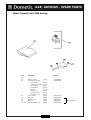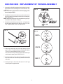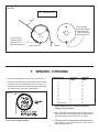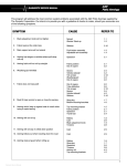
1
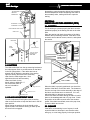
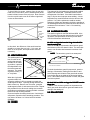
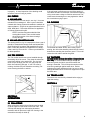
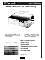
A&E AWNINGS
Model: Dometic A&E 8300 Awning
A&E innovation leads the field again with the
all-new 8300 vinyl patio awning. Its theme is
clean simplicity – yet with all the rugged A&E
quality RVers have trusted for years. It’s
great-looking, long-lasting, easy to operate
and very affordable!
The canopy fabric is reinforced vinyl in
popular Horizon stripe patterns; the
weathershield is durable laminated white
vinyl. And, like all A&E awnings, the 8300 is
stain and mildew resistant, waterproof,
washable and fully UV protected.
• Lengths 10ft to 16ft in one foot increments
A&E Sunchaser 8300
Colours
• Full approx. 8ft extension
• Simple one-person setup
• Sporty coloured canopy top; cool white underneath
• Sleek hardware design
• Handy ergonomic lock knobs
The color in this chart should be used
as a guide only. For exact fabric color,
see A&E's fabric sample kit.
Index
™
USA
Index
Fabric Roller Tube Assemb
Assemblly with
.
.
Square 1™ Har
dware
Hard
CANADA
Cambridge, Ontario
CANADA N3H 2N7
This Manual should be read and understood before
installation, adjustment, service or maintenance is
performed. This unit must be installed and serviced
by a qualified serviceman. Modification of this
appliance can be extremely hazardous and could
result in personal injury or property damage.
For Service Center
Assistance Call:
MODEL
INST
ALLA
TION
INSTALLA
ALLATION
INSTRUCTIONS
Form No. 3106879.004 1/96
©1996 The Dometic Corp.
LaGrange, IN 46761
(French 3108650.007)
Sunchaser
1
INST
ALLA
TION
INSTALLA
ALLATION
the torsion rod using the 1/4–20 machine screws, nylon
washers, and 1/4" locknuts.(FIG. 2A) Align and attach
the other end.
COVERED BY PATENT 4,524,791
OTHER PATENTS APPLIED FOR
FIG. 2A
REQUIRED PARTS (Packed with each Hardware Assembly)
(2)
(2)
(8)
(2)
(2)
(2)
1/4–20 Machine Screws
1/4–20 Short Locknuts
#14 x 2 Screws
#10 Self-Drilling Screws
Stop Washers
#6 Self-Drilling Screws
(1)
Door Roller Kit, Containing:
(2) #10 Self-Drilling Screws
(1) Door Roller
(1) Edge Guard
Application
The A&E Awning is designed and intended for use on
motorhomes, mini-motorhomes, 5th wheels and travel
trailers with straight sides.
IMPORTANT: Read and understand ALL of the following steps before beginning installation.
FIG. 2B
The Dometic Corporation reserves the right to modify
appearances and specifications without notice.
Installation of A&E Awnings will at some points, require
three people. Use the following procedure to assure a
properly installed, and properly functioning awning.
FIG. 1A
Position Wheel
Directly over edge
of Door
Wheel Above
Door 1/4" – 3/8"
ENTRY
DOOR
DO NOT REMOVE the NAIL from the right end at this
time and DO NOT attempt to rotate the Safe-T-LockTM
Lock Direction Lever until installation is complete.
(Lever has been preset in the roll-down position.)
(FIG. 2A)
1. Where the A&E Awning is to be mounted above the
entry door, the door roller must be installed on the
exterior side of the door in the extreme upper corner
above the door handle. (FIG. 1A)
In addition, if there is
a screen door inside the
SCREEN
regular door, a door edge FIG. 1B
DOOR
guard must be installed
DOOR EDGE
on the exterior side of GUARD
the screen door, in the
extreme upper corner
opposite the door
hinges. (FIG. 1B)
This allows the door roller or the edge-guard (instead of the sharp door corner) to contact the underside of the fabric when the entry or screen door is
swung out while the awning fabric is extended low.
3. Remove the left nail only. With both awning arms
secured to the Fabric Roller Tube Assembly, and facing
the floor, rotate the left arm clockwise as if rolling the
fabric up. This takes the torsion pressure off of the nail.
Remove the nail by hand and lower the arm to the floor.
(FIG. 2B)
4. DO NOT remove the tape or spacer holding the arm
and rafter together until the top brackets are installed.
Prepare the awning rail to accept the awning roller
cover by selecting the end from which the awning shall
be fed, then widen that end of the rail with a flat
screwdriver and remove burrs. (FIG. 3)
With one person grasping each support arm, carefully lift the entire assembly to an upright position.
Keeping the two arm assemblies PARALLEL to
each other to avoid excessive twisting and possible
damage to assembly, walk the awning to the prepared
end of the awning rail (FIG. 4A)
2. Carefully lay the fabric roller tube assembly on a clean,
well padded "V" trough to prevent fabric damage.
Working on the torsion lock end first, insert the arm cap
into the arm, position the nail in the end cap to the front
of the hardware, align and secure the arm assembly to
2
FIG. 3
BEFORE
arm and rafter on each side. Install remaining top mounting
bracket using the same procedure. Remove the tape
holding the awning arm and rafter together and unhook the
travel straps after both brackets are installed.
FIG. 4A
AWNING
RAIL
FABRIC ROLLER
TUBE ASSEMBLY
ARM
ASSEMBLIES
TAPE
FIG. 5B
TAPE
AFTER
A third person is now required to guide the full awning
into the awning rail while standing on a stepladder,
while the other two walk the entire awning assembly to
the desired position. (FIG. 4)
5. Loosen the knobs and extend the arms to the ground.
Position the pivot 2 inches above the awning rail.
Retighten the knobs so the arms support the awning
weight.
FIG. 5C
PIVOT
AWNING
RAIL
6. Install Top Mounting Brackets.
After the complete awning assembly has been slid into the
awning rail, check to be sure that its position allows for solid
mounting of the top and bottom brackets and that support
arms are in desired location (not restricting use of doors,
access doors, etc.). (FIG. 5A)
TOP
MOUNTING
BRACKET
DO NOT untape or move the main support arm away
from the top mounting bracket and rafter arm.
#14 HEX. HD. SCREW
#14 HEX.
HD. SCREW
FIG. 5A
TOP MOUNTING
BRACKET
FIG. 5D
AWNING
RAIL
PIVOT
Swing the foot away from the coach as needed to lower the
top pivot to the awning rail height. Insert the pivot into the
awning rail as shown in FIG. 5B.
FIG. 5E
Position the top bracket in the top pivot. Alternate slots
allow for use with various awning rails and constructions.
(FIG. 5C, D, E)
Mark the top bracket hole locations. Predrill the two holes
using a 3/16" drill bit. The hole should angle downward
slightly. (Use 7/32" drill bit if drilling through steel). Install
top bracket with two #14 hex. hd. screws (FIG. 5C, D, E).
Use clear silicon to seal where the screw enters the coach.
The main support arm cap will rest on the top pivot.
Check that there is approximately 1/8 inch between the
TOP MOUNTING BRACKET
#14 HEX.
HD. SCREW
AWNING
RAIL
PIVOT
3
7. Installation of Bottom Mounting Brackets
Brackets.
Position the bottom mounting bracket (FIG. 6) between
66" and 80" below the awning rail, centered on the main
arm with the coach level. Always select the position that
offers the best supporting structure for mounting the
bottom bracket, i.e. mount directly into the floorline, molding, etc.
8. Installation of Stop Washer
CAUTION:
1) This step is essential for the proper functioning
of all A&E Awnings.
2) The top brackets (FIG. 5) must be bolted tight to
the coach to ensure proper stop washer location and proper awning function.
FIG. 6
A. Ensure the arm cap is above the rafter pivot. Hold the
arm snug to the rafter. Loosen the arm knob slowly so
the arm lowers onto the rafter pivot. Raise the inner arm
to where the foot is at the bottom of the foot bracket and
retighten the knob. (FIG. 7A)
FIG. 7A
Mark position of bottom bracket so that both holes are
positioned over the floorline. Predrill two 3/16" dia. holes
through the marked locations. (Use 7/32" dia. if drilling
through steel).
Secure bracket using two #14 hex head screws. (FIG. 6B).
Use clear silicon to seal where the screw enters the coach.
Repeat for other side.
FIG. 6B
B. Lift the weight of the awning with the arm and snap the
foot into place. (FIG. 7B)
FIG. 7B
The bracket must be mounted level. When installing
over a molding, A&E Stand-Off Kit, Part No. 3104781,
may be used.
FIG. 6C
4
C. (Refer to FIG. 7C)
1) Rotate the arm to the coach, holding it against the
rafter again.
2) Loosen the rafter knob so the rafter will slide within
the arm.
FIG. 8
Safe-T-Lock Lever in
Roll Up
Position
FIG. 7C
REMOVE
NAIL
ROLLER TUBE
END CAP
10.
Securing Awning
10.Securing
The fabric must be secured from shifting within the awning
rail.
Open and close awning a few times to allow for natural self
adjustment of awning. Track the strap slightly to one side
as it closes to avoid bulging over the extra thickness of
material and stretching the fabric.
With the awning closed, the fabric will locate itself between
the two top brackets. Pull the main arm sideways to the
rafter so there is no gap between them. The fabric will
move with the roller tube. Measure in 2" from the edge of
the fabric and secure by driving a #6 self-drilling screw
through the rail and into the fabric rope. (FIG. 9)
3) Loosen the arm knob slowly, letting the arm cap
settle onto the rafter pivot.
4) Mark the stop bolt location lightly at the very bottom
of the main arm in the center of the adjustable arm.
5) Lift the arm 1 inch and
6) Retighten the arm knob.
7) Install the stop plug with (1) #10 self-drilling screw
centered to 1/8" above the marked line.
8) Loosen the arm knob, letting the weight settle onto
the stop plug.
The main support arm cap should completely clear the
main rafter and pivot as it swings toward the vehicle.
Repeat for other side. (You may need to push the other
arm, rotating the awning to the coach wall).
Repeat at other end, hold the main arm against the rafter
while securing the fabric.
9. Releasing Pre-Set Tension.
FIG. 9
When removing nails, keep hands clear of hardware
and roller tube. Springs are under tension and the
awning will attempt to close.
The nail is found in the roller tube end cap (FIG. 8). Twist
the roller tube as if unrolling awning while pulling the nail by
hand and discard.
Remove wire tie from the Safe-T-Lock™ Lever. Rotate the
lever to the roll up position and allow the awning to roll up.
The awning should now roll up snugly against the vehicle
side. If no tension is felt, check to make sure the Safe-TLock Lever is in the roll-up position.
11. Operate awning according to the Operating Instructions to check that all parts function properly.
12. Re-secure the travel straps.
TM
5
SERVICE OFFICE
The Dometic Corp.
Fabric Roller Tube Assembly with
Square 1™ Hardware
.
1
OPERATING INSTRUCTIONS
Form No. 3106880.002 1/96
(French 3108603.006)
©1996 The Dometic Corp.
LaGrange, IN 46761
1
MODEL 8300
Sunchaser
TO OPEN
Index
4. From the side of either arm assembly, pull sideways on
the rafter and slide it to the top of the support arm. Place
downward force on main support arm to remove slack
from fabric and tighten black adjustment knob on the
rafter arm. Repeat for other side. (FIG. 4)
1. Loosen the rafter adjustment lock knobs (located
behind the main arm) and unhook the travel straps.
(FIG. 1)
FIG. 1
FIG. 4
RAFTER
ADJUSTMENT
LOCK KNOB
5. Reposition the pull strap out of the way by sliding it down
the fabric roller tube assembly toward the right (same
end as the Safe-T-Lock™). Wrap the strap around the
main support arm. (FIGS. 5A & 5B)
2. Locate Safe-T-Lock™ Lever on the right end cap of the
fabric roller tube assembly. Place the hook of the pull
rod behind lock lever and pull lever forward into the
ROLL DOWN position. (FIG. 2)
FIG. 5A
FIG. 5B
FIG. 2
SAFE-T-LOCK
LEVER
TM
6. To raise awning, grasp arm, loosen knob, and lift the
arm assembly. When the desired awning height is
reached, retighten the knob. Extend other arm assembly to the same height. (FIG. 6)
PULL ROD
3. Insert hook of the pull rod through the loop of the pull
strap. Pull the strap outward and completely extend the
awning. The awning will stay positioned by itself. (FIG.
3)
FIG. 6
FIG. 3
ARM KNOB
2
7. For extended stays and where ground and weather
conditions permit, the patio position allows easier access and more usable space (FIG. 7B):
8. CAUTION: Whenever heavy or prolonged rain or
wind is anticipated, or you will leave the awning
unattended, it is best to close the awning. Damage
as a result of weather is not covered by warranty.
Lower the awning (reverse Steps in Sec. 6)
Grasp the arm and support the awning weight. Push on
the thumb latch and remove the foot from the bracket.
(FIG. 7A)
FIG. 8
Place the support arm down vertically on the ground
and adjust the support arm height. (FIG. 7B)
Accessory hold-down stakes should be installed through
the holes on the awning foot to secure the awning in
case of wind. (FIG. 7C)
FIG. 7A
TO CLOSE
1. FROM PATIO POSITION
Remove the stakes from the awning foot and swing the
support arm up to the bottom mounting bracket. Repeat
on other side.
(FIG. 1)
FIG. 7B
FIG. 7C
FIG. 1
2. FROM VEHICLE MOUNTING POSITION: Grasp the
main arm, loosen the arm knob and lower main support
arm down to the stop plug. (FIG. 2)
CAUTION: DO NOT DRIVE THE STAKES "HOME" AS IT
WILL BE DIFFICULT TO PULL THEM OUT AND MAY
DAMAGE THE AWNING FOOT.
FIG. 2
Repeat this step on the other side to complete the patio
position setup.
ARM KNOB
3
3. To release the rafter arm, loosen black adjustment knob
on the rafter arm and lift up on the slider catch, located
under the slider. Pull sideways on the rafter and slide it
to the bottom of the main arm. DO NOT retighten
adjustment knob at this time. (FIG. 3)
5. Tighten the four adjustment knobs and
secure the travel
straps.
FIG. 3
TRAVEL
STRAP
The awning is now ready for travel.
OWNER MAINTENANCE
HELPFULHINTS
FORAWNING CARE
4. Prepare fabric roller tube assembly for roll-up. While
pulling down on the pull strap or while, from the bottom,
turning the entire roller tube toward you slightly, flip the
Safe-T-Lock™ Lever into the ROLL UP position.
2 Whenever the awning is wet while rolled up, as soon
as conditions allow, roll it out and let it dry before
rolling it up again. This will help prevent mildew and
rotting.
CAUTION: DO NOT release the awning as it is
now under tension and could snap back against
the vehicle side.
2 Always make sure the awning is extended high
Hold the roller tube down and slide the pull strap to the
middle of awning. Using strap for control of speed and
even roll-up, allow awning to return to the vehicle side.
(FIG. 4)
enough before opening entry door.
2 WHEN TO GET MORE HELP:
If malfunctions occur that cannot be corrected by
reviewing this user's guide, contact a qualified
Dometic service technician.
NOTE: Wind the strap diagonally as the awning rolls up
to avoid creating a bulge and stretching the awning
fabric.
Please note: A slight "travel line" may
appear where the door roller contacts
the awning fabric. This is considered
normal and does not affect the integrity of the awning.
FIG. 4
4
A&E AWNINGS - SPARE PARTS
Model: Dometic A&E 8300 Awning
122
A&E AWNINGS - SPARE PARTS
Model: Dometic A&E 8300 Awning
Item
No.
1
2
3
4
10
11
12
8271003.402B
Part No.
Description
Main Arm
A1 Handle. Iift
A2 Rivet
A4 Shim, lift base
A5 Kit, slider catch
Arm, asm. adjustable
B1 Foot diecast
(2 req.)
(2 req.)
(pair)
(2 req.)
C1 Rivet, semi-tube 5/16"x2.59
C2 Rivet, semi-tube 1/4"x2.56
Rafter asm., main
(2 req.)
D1 Bracket asm., top
D2 Rivet, semi-tube
D3 Bumper. rubber
D4 Latch, travel
(2 req.)
Rafter asm., secondary (2 req.)
E1 Slider
E2 Rivet, semi tube 3/ 6” x 1.45 SS
Knob, 5-point
(2 req.)
Nut, special
(2 req.)
Rod, EZ-pull
3104502.426B
830644
308171.020
---830472.002
830466.516B
3108708.342 (Old)
3108708.042 (New)
143002.059
143002.058
830295.542B
3108119.003M
143002.053
141031
3105278.026
830463.512B
830463
143002.055
3105421.014
3104652.007
830152.102
123
A&E AWNINGS - SPARE PARTS
Model: Dometic A&E 8300 Awning
Item
No.
F2
F3
F4
F5
F6
F7
F2 + F3
Description
Bracket, bottom
Kit, hardware, includes
Washer. split
Screw cap. Hex 1/42
Screw *6-20
Screw #10-24
Nut lock
Washer, stop
Screw #14 x 2.0
Screw #14 x 3.0
Screw 1/4-20
Cap, arm
Washer, nylon
Nut, lock
Universal Hardware Kit
Part No.
(2 req.)
(2
(2
(2
(2
(2
(2
(4
(4
(2
(2
(2
(2
(2
req.)
req.)
req.)
req.)
req.)
req.)
req.)
req.)
req.)
req.)
req.)
req.)
req.)
124
3104653.005
3104852.003
3104176.114
3107942.009
309513.054
3106825.007
3104125.020
Kit 3107942.009
A&E AWNINGS - SPARE PARTS
Model: Dometic A&E 8300 Awning
ITEM PART
No. No.
DESCRIPTION
1
3
4
5
Kit pull strap
94.5"
Torsion Asm. Right-hand
Torsion Asm. Left-hand
Roller Tube
10'
Roller Tube
11'
Roller Tube
12'
Roller Tube
13'
Roller Tube
14'
Roller Tube
15'
Roller Tube
16'
Fabric Asm.
10'
Fabric Asm.
11'
Fabric Asm.
12'
Fabric Asm.
13'
Fabric Asm.
14'
Fabric Asm.
15'
Fabric Asm.
16'
6
940001
3108018.080
3108018.098
3108346.010
3108346.011
3108346.012
3108346.013
3108346.014
3108346.015
3108346.016
R3105699 (Colour
R3105699 (Colour
R3105699 (Colour
R3105699 (Colour
R3105699 (Colour
R3105699 (Colour
R3105699 (Colour
Code)
Code)
Code)
Code)
Code)
Code)
Code)
.106
.114
.122
.130
.148
.155
.163
Colour Code:
SEE
INDEX
FOR
CODES
AW = Burgundy
AV = Blue
BE = Coffee
EH = Pewter
Dometic
A&E AWNINGS - SPARE PARTS
Model: Dometic A&E 8300 Awning
Part No.: 3108018.080 TORSION ASSEMBLY – RIGHT-HAND
ITEM PART
No. No.
DESCRIPTION
A2
A3
A4
A6
A10
Asm., cap, end
Pin, spring 3/16” x 1” (2 req.)
Spring, torsion lock
Disk, lock
Spring, torsion, right-hand
3108017.009
3104664.044
3105695.005
3105691.004
3105687.002
Part No.: 3108018.098 TORSION ASSEMBLY – LEFT-HAND
ITEM PART
No. No.
DESCRIPTION
C2
C7
C12
Asm., cap, end
Pin, spring 3/16” x 1”
Spring, torsion, left-hand
3108017.009
3104664.044
3105687.010
Index
8300 8500 9000 REPLACEMENT OF TORSION ASSEMBLY
1. Insert the leg of the idler opposite the torsion spring screw
and washer over the seamed groove of the roller tube. See
FIG. 10.
NOTE: The idler leg opposite the torsion spring screw
has a triangle shape.
FIG. 10
2. Installation of a new roller tube may require a notch cut in
the side of the groove away from lock lever for each poly
rope. See FIG. 11.
NOTE: Insert torsion idler into roller tube before the poly rope
is stretched. See Section E. Step 1.
3. Use pliers to stretch the poly rope 1/4" – 1/2" and tuck it
into the notch and place off to the side. See FIG. 13A13G. Repeat Steps 1 and 2 on opposite end.
FIG. 11
FIG. 12
FT
LE
RIG
H
T
WIND TO
ADD TORSION
CAP A
ROLL
UP
ROLL
DN
FT
LE
RIG
H
T
WIND TO
ADD TORSION
CAP B
ROLL
UP
The left-hand end cap is always positioned with the open
notch over the open groove. See FIG. 13G.
5. Mark the location of rivet holes in the end cap on roller
tube. Drill 3/16" hole. Remove any drill burrs from inside
roller tube.
CAP C
6. Attach end cap to roller tube with two 3/16" x 3/8" pop
rivets. Repeat on opposite end.
5
ROLL
DN
4. Slide torsion assembly into roller tube. Identify the end
cap "A", "B" or "C" (refer to FIG. 12). Position the SafetyT-Lock™ Lever as shown in FIGS. 13A–13F.
FIG. 13A
RIGHT-HAND
END CAP “A”
Fabric without
hemmed edge
Cut Poly Rope flush
with end of tube
See Fig. 11
ROLL
UP
Open
Groove
ROLL
DN
WIND TO
ADD TORSION
FT
LE
RIG
HT
Place open notch
in alignment with
open groove
Valance
Trim Poly Rope
leaving sufficient
length to tuck in
place behind the
open groove
RIGHT-HAND
END CAP “A’
Fabric edge
folded and
hemmed
Place open notch in alignment
with fabric groove
Cut Poly Rope flush
with end of tube
FIG. 13B
LEF
See Fig. 11
T
RIGHT
TO N
D SIO
IN
W TOR
D
AD
LL
RO
UP
Open
Groove
LL
RO D N
Valance
Trim Poly Rope
leaving sufficient
length to tuck in
place behind the
open groove
RIGHT-HAND
END CAP “B”
Place open notch in alignment
with fabric groove
Fabric edge
folded and
hemmed
Cut Poly Rope flush
with end of tube
HT
See Fig. 11
W
ADD IND TO
TOR
SIO
N
ROL
L
DN
LEFT
RI
G
FIG. 13C
ROL
UP L
Open
Groove
Valance
6
Trim Poly Rope
leaving sufficient
length to tuck in
place behind the
open groove
RIGHT-HAND
END CAP “B”
Fabric without
hemmed edge
Cut Poly Rope flush
with end of tube
ROLL
DN
See Fig. 11
ROLL
UP
FIG. 13D
Trim Poly Rope
leaving sufficient
length to tuck in
place behind the
open groove
Open
Groove
WIND TO
ADD TORSION
FT
LE
RIG
HT
Place open notch
in alignment with
valance groove
Valance
RIGHT-HAND
END CAP “C”
Place open notch in alignment
with fabric groove
Cut Poly Rope flush
with end of tube
Fabric without
hemmed edge
FIG. 13E
See Fig. 11
Trim Poly Rope
leaving sufficient
length to tuck in
place behind the
open groove
Open
Groove
Valance
RIGHT-HAND
END CAP “C”
Cut Poly Rope flush
with end of tube
Fabric edge
folded and
hemmed
FIG. 13F
See Fig. 11
Open
Groove
Place open notch
in alignment with
Open groove
Valance
7
Trim Poly Rope
leaving sufficient
length to tuck in
place behind the
open groove
FIG. 13G
LEFT-HAND END CAP
Fabric
Trim Poly Rope
leaving sufficient
length to tuck in
place behind groove
The Left-Hand
End Cap is always
placed with open
notch in alignment
with open groove
See
Fig. 11
Valance
Open Groove
F. WINDING TORSIONS
AWNING LENGTH
1. Insert torsion winding tool into torsion rod. See FIG. 7.
8'
9'
10'
11'
12'
13'
14'
15'
16'
17'
18'
19'
20'
21' AND ABOVE
2. Always have the speed wrench handle at the 6 O-clock
positions and turn towards the side of the coach. Left
hand end cap is turned clock-wise and right hand end cap
is turned counter-clock-wise to add tension.
FIG. 14
*
ROLLED UP
TURNS *
EXTENDED
TURNS*
5
5
5
5
5
6
6
7
7
9
9
10
10
10
11
11
11
11
11
12
12
13
13
15
15
16
16
16
Add 6 additional turns to torsion spring when
awning is fully extended.
3. After torsion spring is wound to proper number of turns,
insert a steel pin in the end cap to prevent rapid spin-off
when reinstalling on coach. See FIG. 3, Page 2.
NOTE: Right hand torsion must have Safe-T-Lock™
lever in the roll-down position.
4. Reinstall awning per the Operating and Installation Manual.
If the awning is not removed from the coach, reverse
disassembly procedure.
8
A&E
Patio Awnings
DIAGNOSTIC SERVICE MANUAL
This program will address the most common system problems associated with the A&E Patio Awnings supplied by
The Dometic Corporation. Our intent is to provide you with a guideline of checks to make, should you encounter one
of the following symptoms.
SYMPTOM
CAUSE
REFER TO
1.
Black adjustment knob will not tighten
Nutsert
Washer Stack-up
1.1
1.2
2.
Fabric leaks at the roller tube
Stitches
2.10
3.
Main support arms will not extend
Push button assembly
Adjustable arm assembly
1.3
1.4
4.
Awning has bulges or wrinkles where pull strap
rolls up
Operation
3.1
5.
Awning fabric will not roll up straight
Fabric position
Out of square
2.1
2.2
6.
Weatherguard wrinkled
Seams
Vehicle sidewall
Tek screws
Weatherguard
Out of square
2.4
4.2
2.12
2.3
2.2
7.
Fabric does not hang well
Out of square
Tube deflection
Tek screws
Seams
Vehicle sidewall
Stitches
2.2
2.6
2.12
2.4
4.2
2.10
8.
Must lift main arm(s) to open or close the awning
Stop plug
Bottom mounting brackets
1.7
1.6
9.
Awning arm(s) stay up against side of coach when
trying to open awning
Top mounting bracket
Fabric position
Operation
Travel lock
1.5
2.1
3.1
3.4
10. Awning will not roll up
Rafters
Cam
Black adjustment knob
Torsions
1.8
2.9
1.9
2.8
11. Awning will not stay in rolled down position
Cam
2.9
12. Awning billows out when traveling down the road
Cam
2.9
13. Awning stops at guard when rolling up
Rafters
Stop plug
Operation
Torsions
Awning rail
Top mounting brackets
1.8
1.7
3.2
2.8
4.3
1.5
1
Diagnostic Service Manuals
A&E
Patio Awnings
SYMPTOM
DIAGNOSTIC SERVICE MANUAL
CAUSE
REFER TO
14. Water leaks through guard
Operation
Guard
Tube deflection
3.3
2.5
2.6
15. Water drips down the side of coach
Awning rail
Rubber seal
4.1
2.7
16. Water leaks through fabric
Fabric
2.11
SECTION 1
1.2 WASHER STACK-UP
HARD
WARE COMPONENTS
HARDW
Washer stack-up merely means the proper positioning of
the washers on the stud of the black adjustment knob.
Remove the knob and check for proper washer position.
The plastic washer should be against the main rafter,
and backed by the metal washer for stiffness. If the
stack-up is not proper it should be corrected.
1.1 NUTSERT OR SPECIAL NUT
The nutsert is simply a threaded fastening device
used to tighten down the black adjustment knob. If
the knob will not tighten, first
remove the secondary rafter
assembly from the hardware.
Turn the knob to determine if
the nutsert is stripped or
NUTSERT
spinning. If so, replace the
nutsert. If you cannot turn the
knob it will be necessary to
replace both the nutsert and
the black adjustment knob.
On some arm assemblies the
nutsert has been replaced with
a SPECIAL NUT
NUT. If the knob will
not tighten, first separate the rafter assembly. Turn
the knob to determine if the special nut is stripped. If
so, replace the special nut. If you cannot turn the
knob, it will be necessary to replace both the special
nut and the back adjustment knob.
SPECIAL
NUT
SECONDARY
RAFTER
PLASTIC WASHER
METAL WASHER
ADJUSTMENT KNOB
1.3 PUSH BUTTON ASSEMBLY
The push button assembly locks the main support arm to
the adjustable arm assembly and controls the height of
the awning in the open position. To check it, open the
awning to full extension. Look inside the main support
arm, and activate the push button to see if the locking pin
is moving in and out of the hole in the adjustable arm
assembly. If the locking pin does not move, or has been
SD 66 BS RIVET
(3/16 DIA. POP
RIVET)
COMPRESSION
SPRING
LIFT HANDLE LOCK BUTTON
3/16" X 1/4"
GRIP
ALUMINUM
POP RIVET
BUTTON
LOCK
BUTTON
RETAINER
MAIN SUPPORT
ARM
NOTE
NOTE: The special nut could be a large hex nut as
well as the one shown.
2
SD 66 BS RIVET
(3/16 DIA. POP RIVET)
#8—32
HEX NUT
A&E
Patio Awnings
DIAGNOSTIC SERVICE MANUAL
broken off, the push button assembly must be replaced.
At times the lock pin of the push button assembly can
break off and jam between the push button housing and
the adjustable arm assembly, making it difficult to extend
the main support arm.
1.4 ADJUSTABLE ARM ASSEMBLY
The adjustable arm assembly allows for telescoping
height adjustment of the main support arm, and it
connects to the bottom mounting bracket to support the
weight of the awning. If the main support arm cannot be
extended freely, the adjustable arm assembly should be
checked. Remove the adjustable arm assembly and
check for nicks, burrs, bends or twists. If any deflection
is noted, the adjustable arm assembly must be replaced.
For ease of operation apply GO-EASY, a special lubricant.
LIFT
HANDLE
ARM
ASSEMBLY
ADJUSTABLE
ARM
NOTE: GO-EASY is available from your distributor.
1.5 TOP MOUNTING BRACKETS
The top mounting bracket supports the main rafter
assembly to hold the awning in the open extended
position, and allows the rafter to pivot into the “C”
channel of the main support arm. Each top mounting
bracket should be mounted directly over the awning rail
so the screws go through the “C” portion of the rail.
TOP MOUNTING BRACKET
On the Series 9000 awning the top mounting bracket
can be mounted lower when possible. If the top mounting bracket is mounted above center of the awning rail,
the aluminum guard may not cover the fabric completely
in the closed position. If this is the case, relocate the
top mounting bracket accordingly.
The top mounting brackets have slotted holes for the
mounting screws, allowing them to be adjusted side to
side. To adjust the brackets, close the awning and
sight down the main support arm and the main rafter.
The clearance on each side of the rafter should be
approximately 1/4 inch. If clearance is not appropriate,
adjust the top mounting bracket(s) as necessary.
1.6 BOTTOM MOUNTING BRACKETS
The bottom mounting brackets
are screwed to the
floor line of the
unit, and they
support the
weight of the
BOTTOM MTG.
BRACKET
awning. They
INSERT
also provide a
BOTTOM
BOTTOM
MOUNTING
quick release
MOUNTING
BRACKET
BRACKET
to set up the
SPACER
#14 X 2-1/2"
HEX. HD. SCREWS
awning in
the patio
position. If a bottom mounting
bracket settles, sags, or becomes loose it can reduce
the clearance between the top casting of the torsion
and the extension of the top mounting bracket, making
operation difficult.
Check the bottom mounting bracket for looseness or
settling, and tighten or reposition it accordingly for
proper operation.
1.7 STOP PLUG
The stop plug is a mechanical stop that supports the
main arm when opening and closing the awning. It
controls the clearance between the top casting of the
torsion to the extension of the top mounting bracket.
This clearance should be 1/4 inch to 1 inch. To adjust
the clearance, raise or lower the stop plug as needed.
On the 9000 and 9500 Series awning the clearance
should be kept to a minimum for best operation.
TOP VIEW OF MAIN SUPPORT
ARM AND RAFTER
MAIN SUPPORT ARM
RAFTER
1/4" CLEARANCE, EACH SIDE
FROM TOP TO BOTTOM OF
ARM ASSEMBLY
3
A&E
Patio Awnings
DIAGNOSTIC SERVICE MANUAL
Attempting to open the awning without first loosening
the black adjustment knobs can damage the slider of
the secondary rafter, making it difficult to open the
awning.
TOP MOUNTING
BRACKET
AWNING RAIL
SECTION 2
FABRIC R
OLLER TUBE ASSEMBL
Y (FR
TA)
ROLLER
ASSEMBLY
(FRT
CLEARANCE
EXTENSION
2.1 POSITION
For the awning to operate properly the fabric must be
positioned properly in the awning rail and on the roller
tube.
Open the awning and check the position of the fabric
between the top mounting brackets. If the fabric is not
centered, remove the tek screws, center it, and replace
the screws.
MAIN SUPPORT ARM
STOP PLUG
MAIN ARM
STOP
PLUGS
#10 LOCK NUT
3/16" DIA. HOLE
CLOSEST TO
MAIN ARM
CLEARANCE
FROM FABRIC
TO END CAP
#6 X 1/2" TEK SCREW
2"
1.8 RAFTERS
The rafters telescope from the top mounting brackets to
the main support arms to provide tension on the fabric
in the full open position. If the rafters are bent or
twisted, this will hinder the operation of the awning.
Open the awning and remove the secondary
rafter from the main support arm. Now
sight down the main and secondary
rafters and check for any
bends, twists or deflection. If
one or the other rafter is
not true it should be
MAIN RAFTER
replaced.
SECONDARY RAFTER
SLIDER
1.9 BLACK ADJUSTMENT KNOB
The black adjustment knob tightens the secondary
rafter to the main rafter to keep the fabric taut in the full
open position.
When closing the awning, the knob should not be
tightened down until after the awning is rolled up and
the travel lock is engaged.
4
AWNING RAIL
TOP
BRACKET
VINYL FABRIC
When the fabric is properly positioned, next check the
position of the fabric on the roller tube. The clearance
from the end cap of the torsion assembly to the edge of
the fabric must be the same on each end. If it is not,
adjust the fabric on the tube as necessary.
On the Elite 9000 and 9500 awning the fabric is held in
place to the weatherguard with 1/8" pop rivets. Check
the position of the fabric at each end of the weatherguard.. If the fabric has shifted, remove the pop rivets,
center the fabric and re-rivet.
2.2 SQUARE
If the fabric on the awning is out of square, it could
cause the fabric to telescope in one direction when
rolling up, or to not hang properly in the open position.
A&E
Patio Awnings
DIAGNOSTIC SERVICE MANUAL
To check fabric for square, measure from the top right
hand corner of the fabric (not the weatherguard) to the
bottom left hand corner at the poly rope. Now measure
from the top left hand corner to the bottom right hand
corner as shown below.
AWNING
RAIL
WEATHER
GUARD
FABRIC
1ST POLY
ROPE
ROLLER
TUBE
DISTANCE FROM FABRIC TO END CAP (SAME ON EACH END)
In this check, the difference of the two dimensions
should be no more than one inch. If it is more, the
fabric is out of square, and replacement would be
necessary.
The seams of the vinyl awning are electronically welded
together with a heat seal. The welded seams are the
strongest part of the fabric. If the fabric has wrinkles or
sags, it may be due to improper seam welding. A close
inspection may reveal the seams to be the source of the
problem. If so, fabric replacement would be needed.
Whenever wrinkles are detected in the fabric, stretching of
the weatherguard should be performed before the fabric is
condemned for bad seams. See 2.3 for stretching
instructions.
2.5 ALUMINUM GUARD
The aluminum guard on the Elite 9000 and 9500 is the
last 15 inches of the awning that encloses it in the rolled
up position, and protects the woven acrylic fiber fabric
from the environment and elements.
On 9000 awnings that have the hinge slat which fits
into the awning rail:
When the awning is fully extended, the aluminum guard
should have an arch of at least 2 inches. The arch helps
water to run off rather than between the sections of the
guard.
NOTE
NOTE: The aluminum guard is not waterproof.
2.3 WEATHERGUARD
The weatherguard is the
last 15 inches of the
awning that encloses
the fabric in the rolled
up position. It protects
the striped fabric from
the environment and
elements. The weatherguard is a heavy 17
oz. vinyl fabric.
#6 X 1/2" TEK SCREW
SECOND SLAT
2" MIN.
2"
TOP SLAT/HINGE ASSEMBLY
BOTTOM SLAT
ELITE 9000 SHIELD ASSEMBLY
AWNING RAIL
TOP
BRACKET
VINYL FABRIC
When the vinyl weatherguard or fabric has
excessive wrinkles, it will be necessary to stretch the
weatherguard or fabric. Open the awning and allow the
fabric to warm up. Remove one Tek screw, grasp the
weatherguard, stretch it, and resecure the screw. Repeat
this procedure for the other end, making sure to stretch
each side an equal distance, keeping the fabric centered
between the top mounting brackets.
Close and reopen the awning three times. If wrinkles are
still present, repeat the above stretching procedure. This
may have to be done 4 or 5 times before all wrinkles
disappear.
To check the aluminum guard for proper arch, open the
awning to full extension, making sure the fabric is taut.
Hold a flat edge to the bottom of the guard and measure
from the flat edge to the inside of the arch at its highest
point. If the measurement is less than 2 inches, the guard
should be replaced.
On both 9000 and 9500 awnings that DO NOT have the
hinge slat
slat:
The arch of the aluminum guard is not important as the
fabric goes under the aluminum guard and attaches the
awning to the awning rail.
2.6 ROLLER TUBE
2.4 SEAMS
5
A&E
Patio Awnings
DIAGNOSTIC SERVICE MANUAL
9000 WITH HINGE SLA
T
SLAT
E
C
D
D
D
A - VINYL STRIP
B - HINGE SLA
T
SLAT
C - TOP SLA
T
SLAT
D - MAIN SLA
T
SLAT
E-A
WNING RAIL
AWNING
VINYL STRIP "A"
D
D
INSTALL A 1/8"
POP RIVET
EACH END
HINGE SLAT "B"
TOP SLAT "C"
VIEW RH END
E
5/16" CHANNEL
BOTH ENDS
C
MAIN SLAT "D"
VIEW RH END
D
D
D
5/16" CHANNEL
INSTALL TOWARD
CANOPY
1/4" CHANNEL
INSTALL TOWARD
AWNING RAIL
D
3/8" CHANNEL
FOR VINYL
STRIP "A"
HINGE SLAT "B"
D
1/4" CHANNEL
INSTALL A 1/8"
POP RIVET
EACH END
9000 AND 9500 WITHOUT HINGE SLA
T
SLAT
6
VINYL STRIP "A"
5/16" ROD IN
AWNING RAIL
A&E
Patio Awnings
DIAGNOSTIC SERVICE MANUAL
The roller tube is a 3-1/2 inch diameter tube. It has three
symmetrical grooves to retain the poly ropes of the awning
fabric.
If the fabric appears to have more than normal sag, the
roller tube deflection must be taken into consideration.
Depending on the length of the awning, the roller tube can
deflect from one to five inches with the awning in the open
position.
Installing a tension rafter will usually remove 80 per cent of
sag and roller tube deflection. All awnings 22 feet and
longer should be installed with heavy duty hardware which
includes a center tension rafter, a center supporter, and
heavy duty adjustable arm assemblies.
If the roller tube is bent, it will bounce up and down when
opening and closing the awning. On the 9000 Series this
can cause the aluminum guard to leak, because the guard
assembly may not be tight.
provides tension on the roller tube to roll the awning up
into the travel position.
The right hand torsion end cap contains a cam assembly which prevents the awning from billowing or unrolling during travel. It also allows one-person set-up of
the awning by preventing rollback.
When difficulties are experienced in rolling the awning
up, the tension on the torsion should be checked. In
#6 MACHINE SCREW
TOP CASTING
WASHER
END CAP
WITH ASSY.
3/16" POP RIVETS
2.7 RUBBER SEAL
On the 9000 Series awning(see Section 2.5), an extruded black rubber seal is located at the awning rail of
the coach. The seal slides into the metal hinge which
connects the aluminum guard to the awning rail. This
seal is designed to prevent water from running down the
side of the coach.
To check, inspect the full length of the seal for proper
positioning, and for cuts, tears or wrinkles. If any of
these problems are found, the seal should be repaired or
replaced.
On some units it may be necessary to silicone seal the
lips of the rubber seal to the awning rail and the top slat
of the aluminum guard as shown , to prevent water from
running down the side of the RV.
TORSION SPRING/
STABILIZER ASSEMBLY
IDLER SLEEVE
STABILIZER
TORSION ROD
2.8 TORSION
ROLLER TUBE
SILICONE SEALANT
TOP SLAT
HEX LOCK NUT
FABRIC
RUBBER SEAL
most cases adding a few turns of torque to each end
will correct the problem. If all tension has been lost,
refer to the following chart and apply the specified
number of turns as indicated. This must be done with
the awning extended two feet away from the coach.
.
METAL HINGE
AWNING RAIL
9000 AWNINGS
WITH HINGE
SLAT
The torsion assembly has a wound coil spring which
7
A&E
Patio Awnings
DIAGNOSTIC SERVICE MANUAL
TORSION ASSEMBLY TORQUE SPECIFICATIONS
Number of Turns
MODEL NUMBER
5000
7000
6
6
6
6
6
6
7
7
8
8
10
10
11
11
11
12
12
12
12
8
8
8
8
9
9
10
10
12
12
13
13
13
-
Awning Length (Ft.)
8
9
10
10' 8"
11
12
13
14
15
16
16'6"
17
18
19
19'6"
20
21
22
23
24
25
1234567
1234567
1234567
1234567
7500
8000
8500
9000
9500
Grande Pavillion
8
8
8
8
8
8
9
9
10
10
12
12
12
13
13
13
13
12345678901
12345678901
14
12345678901
12345678901
12345678901
14
12345678901
12345678901
14
12345678901
12345678901
14
12345678901
12345678901
6
6
7
7
8
8
8
9
9
See Spring Indentification Chart for No. of Turns
AWNING RAIL
TOP CASTING
RIGHT HAND SIDE
(VIEWED FROM FRONT)
AWNING RAIL
TOP CASTING
LEFT HAND SIDE
(VIEWED FROM REAR)
When winding the torsion, be sure to wind in the proper
direction.
SEVERE INJURIES CAN RESULT FROM
THE SPINNING TOP CASTING. USE VISE
GRIPS® (NEVER BARE HANDS) TO
GRASP TOP CASTING WHILE LOADING
TORSION.
Note: Rewinding must be done with the
Awning Fabric extended two feet away
from the coach.
2.9 CAM
The cam assembly locks the roller tube from turning in
8
SPRING IDENTIFICATION CHART
Standard
Wire Dia.
Heavy Duty
.120
.140
RH
Painted red cap
end and no paint
on stabilzier end.
Painted red cap
end and white
on stabilzier end.
LH
No paint on either
end.
Painted white on
cap end and no
paint on stabilizer
end.
Length
22'
23'
24'
25'
TURNS OF TENSION
14
14
14
14
8
8
8
8
one direction or the other according to which way the
cam lock lever is flipped.
To check the cam lock on the A&E awning, unlock the
main support arms. Hook the pull rod into the pull strap
and try to open the awning. Be sure the cam lock lever
is in the roll-up position. If the roller tube rotates 1/2
turn or more the cam lock must be repaired or replaced.
To check the roll-down position of the cam lock, open
the awning to full extension. Grasp the roller tube with
your hands and try to turn the tube in the direction it will
roll up. If the tube can be rotated 1/2 turn or more the
cam lock must be repaired or replaced.
2.10 STITCHES
The side hems and poly ropes of the awning are
stitched in with a sewing machine. At times the stitches
can allow water to leak through to the inside of the
roller tube. On vinyl awnings the stitches should be
sealed with seam sealer, available at sporting goods
stores. This will stop the water from running down the
inside of the roller tube. For the woven acrylic fabric of
the 9000, 9500 Series awning, Acrylife is an approved
sealant.
When sewing in the poly ropes of the fabric, if a straight
line is not followed it could cause the fabric to hang
A&E
Patio Awnings
DIAGNOSTIC SERVICE MANUAL
improperly. A close inspection of the stitching could
reveal the cause of a sag or pucker.
2.11 FABRIC
A. 9000 AND 9500
The awning fabric is woven acrylic, not vinyl. It is water
resistant but not waterproof. Once a year it should be
cleaned with Canopy-Clean and resealed to maintain its
water resistance. Acrylife is an approved sealant for the
9000, 9500 fabric. Follow the directions for application
of Canopy-Clean and Acrylife.
If the pull strap is rolled up at one end of the awning, it
can cause the fabric to telescope in that direction during
roll-up, and create a bulge or wrinkles at that end. This
could cause the awning arm to stay against the side of
the coach when trying to open.
3.2 CLOSING
NOTE: Avoid touching the underside of the
awning fabric when it is wet, as this breaks
the surface tension of the water causing it
to seep through.
PULL STRAP
B. 8500 AND GRANDE PAVILLION
The awning fabric is vinyl. It is waterproof. Once a year it
should be cleaned with Canopy-Clean and treated with
Vinyl Formula 201 to protect and extend the life of the
fabric. Follow the directions for application for CanopyClean, and Vinyl Formula 201. Contact your distributor
for these products.
2.12 TEK SCREWS
The Tek screws are the two screws installed through
the awning rail of the coach. They keep the aluminum
guard from shifting in the awning rail. On vinyl and
some acrylic awnings (see Sec. 2.5) they keep the
fabric from shrinking with age. If one Tek screw is
missing, the fabric will pull toward the remaining Tek
screw causing the fabric to wrinkle.
#6 X 1/2" TEK SCREW
2"
On the 9000 and 9500 Series, when rolling up the
awning, the roller tube assembly should not be slowed
down before reaching the aluminum guard. This could
cause the roller tube to stall at the guard.
3.3 TAUTNESS
On 9000 Sereis awnings that utilize a hinge slat (see
Sec. 2.5): To minimize water leakage through the
aluminum guard, the fabric must be taut when the
awning is extended. This will keep the sections of the
aluminum guard tight against each other. Before
tightening the black adjustment knob, be sure to apply
enough downward force on the main support arm to pull
the fabric taut.
3.4 TRAVEL LOCK
The travel lock must be fully released before trying to
open the awning.
SECTION 4
AWNING RAIL
MAIN SUPPORT ARM
TOP
BRACKET
FABRIC
UNLOCK
TRAVEL
LATCH
MAIN SUPPORT ARM
LOCK
TRAVEL
LATCH
SECTION 3
OPERA
TION
OPERATION
3.1 PULL STRAP
When closing the awning the pull strap must be rolled
up at an angle from the center of the roller tube. This
will keep the awning from telescoping forward or
rearward, and will prevent a bulge from forming in the
area where the strap is rolled up.
9
A&E
Patio Awnings
AWNING RAIL
4.1 LEAKAGE
When water drips down the side of the coach, the seal
between the coach and the awning rail must be
checked. If improper seal is detected, reseal the
awning rail.
4.2 STRAIGHT
Before condemning the fabric for sags or wrinkles, the
awning rail should be checked. Open the awning and
sight down the rail to see if the rail or sidewall varies up,
down, inward or outward. This must be taken into
consideration when checking a fabric.
DIAGNOSTIC SERVICE MANUAL
There are three types of awning rail used in the RV
industry. Of these, type A and B (see below) are
acceptable for use on the 9000 Series awning that
utilizes a hinge slat (see Sec.2.5) . Type C should never
be used on the 9000 Series that utilizes a hinge slat
(see Sec. 2.5) as it could cause a binding problem on
the aluminum guard assembly, but it is acceptable on
the vinyl awnings.
A
B
C
OPENING
OUTWARD
OPENING
UPWARD
OPENING
DOWNWARD
4.3 TYPE
10