1
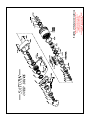
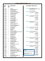
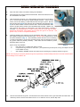
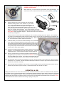
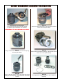
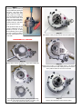
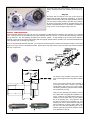
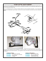
ADVANCE ADAPTERS INC.
P/N: SATURN
P.O. Box 247, 4320 Aerotech Center Way
Paso Robles, CA 93447
Telephone: (800) 350-2223
Fax: (805) 238-4201
PAGE 1 OF 10
Page Rev. Date: 08-05-10
SATURN OVERDRIVE ASSEMBLY
KIT CONSISTS OF:
No.
Qty
1.
2.
3.
4.
5.
6.
7.
8.
1
1
1
1
1
1
5
5
Part No.
Description
911806
911236
911137
911133
911157
911144
GEAR ASSEMBLY (29 or 26 Tooth)
HOUSING ASSEMBLY
SPECIAL TABBED LOCK WASHER
SPECIAL SNAP RING
BODY GASKET
OIL SCOOP
SEAL WASHERS
H.H.C.S. 3/8"-16 x 3-1/2" LG.
One of the most critical factors in performing a successful Saturn Overdrive installation, is the proper installation of the
tabbed washer and special snap ring. If these are not properly installed, the overdrive assembly can slip out of position
and cause gear damage that is not covered by warranty.
The second most important part of the installation is the proper alignment of the brass synchro ring onto the synchronizer
assembly. Advance Adapters has installed the brass ring onto the synchro assembly by use of some heavy wheel bearing
grease. This extra grease will maintain the proper location of the synchro ring while being installed onto the gear assembly.
If there are any questions as you are performing this installation, please do not hesitate to call the factory for assistance.
The third most important part of the installation the oil supply, The oil scoop is the only way oil is fed to the bearings in
the Saturn OD. We have seen units completely destroyed after just a 50 miles because the oil scoop was left off the unit.
SPECIAL NOTE: The components packaged in this kit have been assembled and machined for specific type of conversions. Modifications to any of the components
will void any possible warranty or return privileges. If you do not fully understand modifications or changes that will be required to complete your conversion, we
strongly recommend that you contact our sales department for more information. This instruction sheet is only to be used for the assembly of Advance Adapter
components. We recommend that a service manual pertaining to your vehicle be obtained for specific torque values, wiring diagrams and other related equipment.
These manuals are normally available at automotive dealerships and parts stores.
T
his all-range overdrive is a great addition to any of the early model Jeeps from 1940 to 1971, and I.H. Scouts 1961-65
with the Model 18 transfer case. The addition of this 25% overdrive unit offers you the needed gearing the early Jeeps were
lacking. The Saturn overdrive is a fully synchronized unit that can be shifted-on-the-fly. When installing the unit, only minor modifications are required to the floorboard for the shifter. The Saturn is built to handle up to 300 ft./lbs. of torque, well within the range of a
stock V8. If you are interested in a lower gear set for your Dana 18 transfer case, but would like to retain your overdrive,
we offer a Saturn bowl gear that will work with the gear reduction kits currently on the market. (See the Jeep Dana 18
& 20 Upgrade section for more information on low gear sets). If a low gear set is purchased, we have available a Saturn
overdrive less the bowl gear.
The Saturn is the original unit designed and developed by Warn Industries. Soon after their introduction, another unit emerged in
Colorado by the name of Husky or Dual-A-Matic. The Colorado unit was identical in appearance, but in no way was it interchangeable with the Warn All-Range. Both units were available for the early Jeep and Scout vehicles. The units were offered with the 6 and
10 spline internal assembly and the 26 or 29 tooth output gear. Both units were very popular in the mid-1960s, but it wasn't until the
introduction of the Dana Spicer Model 20 transfer case in 1972 that production quantities started to recede. The Warn and Husky
overdrives were no longer compatible. Both companies stopped production, and the availability of spare parts became very scarce
by the mid-1970s.
Advance Adapters purchased the tooling, engineering data, & inventory from Warn Industries in 1991. The components we manufacture today are the same as the old Warn components. We have incorporated a few upgrades on the units we sell today, but these
units are all still interchangeable with the original Warn overdrive. (Note: The Saturn is not compatible with the Husky unit.) The
Saturn overdrive installs directly on the backside of the transfer case through the inspection cover. No cutting or modification of the
drivetrain is required. No relays and electrical connections required.
APPLICATION INFORMATION:
To select the proper overdrive model, find your vehicle model and
transmission type listed below. The Saturn overdrive will only fit the
vehicles listed that have a Dana 18 transfer case.
Part #
915670
Description
26T x 6 spline
Vehicle Models
M38, M38-A1, CJ2A, CJ3A,
some CJ3B, 4-63 4X4, 4-73 4X4
915672
29T x 6 spline
CJ5, CJ5A, CJ6, CJ6A, 4-74 4X4,
some CJ3B, 6-266, 6-230
915674
29T X 10 spline
(T14 trans) CJ5, CJ5A, CJ6, CJ6A
915676
31T X 10 spline
(Mitsubishi Jeep only)
915677
6 spline overdrive (minus the bowl gear) designed
for the Tera Low & Jack O’Brien low gear sets.
915678
27T x 6 spline
SHIFTER APPLICATION:
(Shifters are sold separately.)
Part #
920000
920001
920003
920013
Description
T90 Dual Handle T/C
T90 Single Handle T/C
Universal Saturn Shifter
T14 Shifter
Top View
Some early Jeeps had a 27 thooth
drive gear.
SATURN OVERDRIVE ONE (1) YEAR LIMITED WARRANTY
The manufacturer warrants this product against material defects and faulty workmanship for a period of one (1) year from the time of shipment on
the Saturn Overdrive. We do not offer any type of labor allowance, and all warranty claims are subject to inspection by Advance Adapters. It is the
customers responsibility to return possible warranted parts to Advance Adapters. The customer will be refunded for shipping costs incurred if the
product is found faulty. We reserve the right to repair or replace any product. All returns must have a Return Goods Authorization Number
(RGA#). Please call 1-800-350-2223, and our sales department can assist you. Warranty is void if proper gear lubricates are not used, the proper
oil levels are not kept, the product has not been properly installed, and/or installation instructions have not been followed.
* INCREASES ENGINE & DRIVETRAIN LIFE
* REDUCES ENGINE RPM’s BY 25%
* IMPROVES GAS MILEAGE
* NO DRIVELINE MODIFICATIONS
* CAN BE USED IN OVERDRIVE OR DIRECT
* ONE (1) YEAR WARRANTY
Benefits of the Saturn Overdrive:
SATURN OVERDRIVE PARTS LIST
PART
NO.
QTY DESCRIPTION
REQ.
COMPONENT ASSEMBLY KITS
911043
911067
911069
911071
911078
911088
911090
911091
911092
911093
911094
911095
911096
911097
911098
911099
911100
911103
911105
911106
911107
911108
911109
911130
911131
911133
911137
911143
911147
911236
911313
911316
911326
911328
911330
911334
911336
911337
911338
911341
911342
911346
911731
911731-S
911806
911838
912388
913296
913297
914231
914232
914384
914384-S
914862
915132
915204
916779
919866
919869
1
2
3
3
1
1
4
2
1
1
2
1
1
1
1
2
2
1
1
1
1
1
1
1
1
1
1
1
2
1
1
4
1
1
1
1
1
1
4
8
8
1
1
1
1
1
1
1
1
2
1
1
1
1
1
1
1
1
1
911349
SEAL AND GASKET KIT
KIT INCLUDES ALL GASKET SEALS
& SEAL WASHERS
912821
THRUST BEARING KIT
KIT INCLUDES: (2) 911099
(2) 911094
(2) 911100
918963
4-PC PLANETARY GEAR SETS
KIT INCLUDES: (8) 911341
(8) 911342
(4) 911316
(4) 911090
(4) 911338
911362
SPLINED SHAFT KIT
KIT INCLUDES: (1)
(1)
(1)
(1)
(1)
HEX NUT
BRASS SYNCHRO-RING
SYNCHRO DOG
SYNCHRO SPRING
SHIFTER SLIDER RING
O’BRIAN’S 4WD BOWL GEAR
PIN, PLANETARY GEAR
NEEDLE BEARING
26-TOOTH GEAR
29-TOOTH GEAR
THRUST RACE
THRUST WASHER
31-TOOTH GEAR
27-TOOTH GEAR
TERA LOW BOWL GEAR
NEEDLE BEARING
THRUST WASHER
SHIFTER FORK
SPRING, SHIFT DETENT
SHIFT DETENT BALL
SHIFT RAIL SEAL NEW STYLE
SHIFT RAIL O-RING SEAL
SPACER WASHER
GASKET CASE
GASKET BODY
OIL SCOOP
O-RING
NEEDLE BEARING
RETAINER RING SUN GEAR BEARING
SPECIAL SNAP RING
ROLLER BEARING
THRUST WASHER
BEARING CAP
CASE COVER
6 SPLINE SHAFT
SPACER WASHER
GASKET CAP
STATIONARYMEMBER
14-TOOTH GEAR
THRUST WASHER
NEEDLE BEARING STRIP
DRIVE MEMBER
DRIVE NUT
SPECIAL METRIC DRIVE NUT
LOCKWASHER
RETAINER RING
ROLL PIN
SHIFTER SHAFT
SHIFTER GUIDE PIN
SOCKET HEAD SCREWS 6-32 X 1/4
PLANET HUB ONLY-6 SPLINE
PLANET HUB ONLY-10 SPLINE (T14)
PLANET HUB ONLY SPECIAL 10 SPL.
CAP SCREW SHIFTER
COTTER PIN
SATURN CASE
SNAP RING/PLAN HUB
RETAINING RING PLANET PINS
RING OIL SLINGER
911043
915132
911143
911147
911330
911317
SYNCHRO RING SERVICE KIT
KIT INCLUDES: (2) 911067
(3) 911069
(3) 911071
911318
SYNCHRO ASSEMBLY KIT
KIT INCLUDES: (2) 911067
(3) 911069
(3) 911071
(1) 911078
(1) 911346
911223
26 TOOTH PLANETARY HSG. KIT
KIT INCLUDES: (1) 911092
(2) 911091
(1) 919869
911224
29 TOOTH PLANETARY HSG. KIT
KIT INCLUDES: (1) 911093
(2) 911091
(1) 919869
911837
PLANETARY ASSEMBLY (6 SPL.)
KIT INCLUDES: (1) 914232
(4) 911090
(1) 911095
(1) 911137
911839 (4) 911316
PLANETARY ASSY. (T14 10 SPL.)
(4) 911338
911840 (8) 911341
PLANETARY ASSY. (METRIC 10 SPL.)
(8) 911342
THESE KITS INCLUDE THE SAME
(1) 911731
PARTS AS 911837
(2) 919866
(1) 916779
(1) 911143
SATURN INSTALLATION PROCEDURES
1.
Drain and flush transfer case before starting with installation.
2.
Put transmission into reverse gear and set hand brake. Remove shift knob, floor mat,
and transmission floor plate.
3.
Clean the transfer case and P.T.O. unit (if installed). Remove the rear cover plate or
P.T.O. unit and clean all surfaces of gasket material and burrs. Using a socket
wrench, remove the retaining nut that holds the stock drive gear in place. Remove
the main drive gear (Fig 1) and make sure the new planetary gear assembly (Fig.
2) has the same number of exterior & interior teeth. Check the transmission main
shaft for end play and the transfer case intermediate gear assembly. Replace any
worn bearings and inspect the transmission rear output shaft bearing, replacing if
necessary. (If installing Model No. 915674 overdrive unit, be certain that the spacer
between the transmission output bearing and the main drive gear is not removed. This
spacer is only on the T14 3 speed transmission).
4.
(Fig. 1)
Install the planetary gear assembly onto the transmission main shaft. Using 1/2” socket
drive, tighten the drive nut to 100-120 ft./lbs. torque. DO NOT USE an impact wrench. Install
the special lockwasher (Fig. 3). This lockwasher prevents the drive nut from loosening.
To retain the lockwasher, we have also provided a square snap ring that fits into the snap
ring groove inside this planetary assembly. These items must be installed to prevent
premature failure of this unit.
(Fig. 2)
Square snap ring installation:
a.
Use "snap ring" or "needle nose" pliers to install.
b.
Compress the ring until the two ears touch. (If compressed beyond this point, the ring will collapse and will
not be suitable for use).
c.
After installing, DOUBLE CHECK and make sure the retaining ring is properly seated in its groove.
NOTE: If the snap ring is not properly seated in its groove, the planetary unit will eventually work loose on the main shaft and cause
severe damage to the overdrive unit.
(Fig. 3)
5.
Lift both rear wheels off the ground. Put transmission into neutral, transfer case in gear and release the hand brake. Turn
driveline by hand to check for free rotation and run out. If rotation is not free, recheck Step 3 & 4.
(Fig. 4)
6.
Install the oil scoop into the case assembly (Fig. 4). NOTE: Be sure the oil scoop
7.
Before assembly, you must verify the proper location of the gear assembly. This
measurement of .677" if taken from the case to the top of the planetary. (See Fig. 5).
is in place. Failure to install this scoop will cause lack of proper oiling and
eventual overdrive failure.
(Fig. 5)
8.
Align the gasket to the rear of the transfer case and install the
aluminum housing portion of the overdrive to your transfer
case. Caution should be taken to make sure the brass synchroring is properly seated before mating these units together. The
three steel keys must interlock with the brass synchro-ring. We
have packed grease underneath the synchro-ring to prevent it from
falling out of position during assembly. If the synchro-dogs do not line up
properly, you will find a 1/4" gap between transfer case and overdrive housing. DO
NOT FORCE these components together. We have seen failure occur because of
synchro-ring misalignment.
Further precaution must be taken when installing your unit so that the planetary gears mesh properly. The overdrive unit
may need to be rotated slightly to allow the gears to align correctly. Once the unit is mounted flush to your transfer case,
install bolts with lock washers and tighten to 30 ft./lbs. torque. Make certain the seal washer is installed as shown in (Fig.
6). Turn the driveline by hand to check for free rotation.
9.
Install the shifter pivot mount and handle assembly to the transmission
case. Before connecting the shift lever rod to the Saturn shift rail, you must
remove and discard the small tube that was installed on the unit’s shift rail.
Connect the shift lever rod to the overdrive unit and the shifter handle. Make
sure you have proper clearance between shift rod, transfer case shifter, and
vehicle body to assure quiet operation.
10.
Using the new shift boot retainer plate as a pattern, mark and cut a new lever
opening in your transmission floor plate (removed earlier). Install this
modified floor plate. Install the shift boot retainer plate and shift boot.
11.
Now is a good time to fill your transfer case with the proper lubrication. A
high grade of gear oil (75-90w) is recommended. We DO NOT recommend
the use of additives in the gear oil. The oil level in the transfer case must
be maintained at proper levels to assure maximum overdrive durability.
(Fig. 6)
12.
Put the transfer case in neutral, the transmission in high gear, and the overdrive in the overdrive gear. Run the engine at
a fast idle for 7 to 10 minutes. This will circulate the oil through overdrive unit. Stop the engine and recheck the oil level in
transfer case, and refill if necessary.
13.
About 100 miles after the installation of the overdrive, check and retighten the five (5) bolts that hold the overdrive unit to the
transfer case (30 ft./lbs. torque) if necessary. Recheck the transfer case oil level once again.
OPERATION & USE:
Shifting the overdrive is done in the same manner as with a standard transmission, which is to release the throttle, depress the
clutch pedal and shift. On automatic applications, the transmission should be shifted into neutral. When the shift lever in the forward
position, the unit is engaged in overdrive. When the handle is shifted back towards the driver, the unit is in direct. The Saturn is
designed mainly to be used as an overdrive; however, it can be used in any transmission gear-shifted in direct or overdrive. Caution:
The unit should not be used in overdrive when towing or pulling a heavy load.
SATURN BREAKDOWN & ASSEMBLY INSTRUCTIONS
Planetary & Case Assembly
The overdrive has two basic parts which include
the planetary gear assembly & case assembly.
Step P3
Remove the thrust bearing sets. Take note that the thickest
race is next to the gear housing.
DISASSEMBLY OF THE PLANATARY GEAR ASSY.
Step P1
Using a small flathead screwdriver, remove the snap ring
from the gear housing.
Step P4
Remove the thrust washers & bearing. Take note that the thin
race is next to the spider assembly.
Step P2
Using a 7/64” Allen wrench, remove the socket head screws
holding the beveled spacer. (Early model Warn units used 2
roll pins).
Step P5
Thoroughly clean & inspect all parts for wear. Replace if
necessary.
Step 6
Planetary gears & bearings
may be replaced by driving out
the pins. (On some early
model units, these pins were
held in place by a small roll
pin). By pushing the planetary
pins out with a 5/16” drift
punch, the roll pins will shear.
Inspect the thrush washers,
needle bearings, planetary
pins and gears for wear.
Units produced today do not
use the planetary pins retained by a roll pin. To keep
these planetary pins in place
we use a snap ring retainer
that fits underneath the synchro-teeth.
Step C2
Remove the cotter pin that locks the nut to the spline shaft.
DISASSEMBLY OF THE CASE
Step C1
Using a 9/16” wrench, remove the 4 cap screws holding the
bearing cap.
Bearing cap & screws removed. (During the reassembly,
the 4-3/8” cap screws should be torqued to 19 ft./lbs., and
the 1/4” cap screw to 6 ft./lbs. of torque)
Step C3
Remove the nut using a 12” adjustable wrench. The shift fork
must be at the rear of the case, locking the unit in the overdrive position before the nut can be removed.
Step C4
Remove the shift detent screw, ball and spring.
Step C5
Thoroughly clean and inspect all parts. Replace any if necessary. Reassemble the case assembly in the reverse order.
Step C6
Be certain that the notches in the rear synchro-rings are
aligned with the shifter dogs when assembling. To properly
retain the outer brass synchro-ring during assembly, we recommend using a quality grease to hold this ring in position.
All internal components should be lubricated during reassembly using SAE 90w gear oil. Remember to install the oil
scoop, as it is crucial for proper oiling of the unit.
SPECIAL CONSIDERATIONS:
The photo below represents the snap ring, lock ring, and retaining nut that fastens the planetary gear assembly to your transfer
case. These items are only accessable once the case assembly has been removed. To remove the case assembly, unbolt the
five (5) 3/8” bolts. The case assembly should then be removed. (NOTE: On high mileage units, the unit may be difficult to
seperate. This is due to the caged needle bearing that was originally pressed into the planetary hub. DO NOT dissassemble the
case assembly from the bearing cap inward.)
Once the case assembly has been removed, you should have access through the middle of the planetary housing to remove the
snap ring, lock ring, and nut. See illustration below. Whenever the snap ring and lock ring are removed, they should be replaced
with new components.
The design of the planetary housing has undergone a few changes from the early Warn & Saturn
units.
One of the biggest problems when installing &
removing this unit from a vehicle is the caged
needle bearing that rides on the 6 spline shaft.
This bearing required a pressed fit when installed
into the planetary housing.
New design
Old design
Today we have designed the planetary hub and
the 6 spline shaft to simplify the installation & removal. Instead of the caged bearing being preinstalled on the 6 spline shaft, we now install it
first in the planetary hub. This required a snap
ring groove machined in the planetary hub. The
retaining hub on the 6 spline shaft was removed.
Current production of these 6 spline shafts, with
the use of the older style planetary hub, will require this snap ring groove to be machined. Refer
to the illustration on the left.
SATURN SHIFTER LINKAGE ASSEMBLY
There are 4 linkages available for the Saturn overdrive. Illustrated below is the linkage for a T90 dual lever transfer case. The
pivot bracket on most linkages bolts to the 2 front top cover bolts of the transmission. The universal Saturn shifter bolts to the top
2 holes of the Dana 18 transfer case.
Little or no modifications will be necessary for linkages offered for the stock transmission assemblies. On the universal shifter
application, some fabrication may be required. This is due to the various transmission assembles that could be installed in the
vehicle.
Both above photos illustrate the shift rod installation on the Saturn Overdrive. The shift rod must remain in close proximity to the
overdrive unit for proper floorboard clearance. The configuration of some of the shifter rods are to avoid transfer case shifter lever
interference.
SATURN SHIFTERS
P/N 920000
T90 Dual Lever T/C Shifter
P/N 920001
T90, T86 Single Lever T/C Shifter
P/N 920003
Universal Shifter
P/N 920013
T14 Shifter
SHIFTER COMPONENTS
P/N 920021
Dual Lever Rubber Boot
P/N 920022
Dual Lever Retainer Ring
P/N 920023
Universal Rubber Boot
P/N 920024
Universal Retainer Ring