1
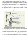
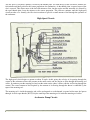
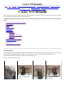
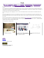
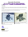
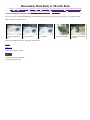
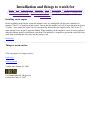
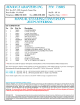
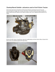
Carter WO 101
[ Home ] [ Up ] [ Carter WO 101 ] [ Parts Kits ] [ Tools ] [ Disassembly ] [ Cleaning and Inspection ]
[ Reassembly Throttle Body ] [ Reassembly Main Body ] [ Reassembly Main Body to Throttle Body ]
[ Reassembly Bowl Cover ] [ Reassembly Air Horn ] [ Installiation and things to watch for ] [ Carter Bulletin ]
Carter WO – 101
The Carter WO comes in two models, 596S on CJ2As before SN212110 and 636SA.on later CJ2As and all
CJ3As. There are some differences but there are insignificant to this article.
This carburetor is very simple as far as carburetors go. There are only five circuits. However, as with all
carburetors, it is a precision device and needs to be handled as such. To allow for an easier understanding of the
carburetor as a whole, This article will discuss the circuits individually. The five circuits are: float circuit, low-speed
circuit, and high-speed circuit, accelerator pump circuit and finally the choke circuit.
To enhance our understanding of carburetor operation, we must understand that the fuel in the fuel-bowl is at
atmospheric pressure. This pressure is about 14.7 pounds per square inch absolute (PSIA). The engine and venturi
of the carburetor creates a low pressure. The atmospheric pressure actually pushes the fuel up passageways into the
throat of the carburetor where it is mixes with air to create a combustible mixture.
The proportions of this mixture are critical and the carburetor’s job is to keep them optimum. To achieve these
optimum proportions the orifices or jets in the carburetor are calibrated by the factory. The orifices must be kept at
their designed size for the carburetor to perform its function optimally.
Float Circuit:
The float circuit controls the fuel level in the carburetor bowl. If the level is too high excessive fuel will be provided
and the mixture will be too rich. Conversely, too low of a level will cause the mixture to be too lean. Both of these
will lead to poor performance and can be taken to the extreme. An extremely high fuel level can cause raw fuel to
spill into the venturi at idle causing flooding. An extremely low fuel level will result in the negative pressure at the
end of the nozzle being insufficient to pull enough fuel from the bowl to allow the engine to do anything but Idle.
end of the nozzle being insufficient to pull enough fuel from the bowl to allow the engine to do anything but Idle.
Fuel enters the fuel bowl through a valve called a needle and seat. The needle is pressed against the seat by the float
to shut off fuel. When the fuel level drops to a level where the needle moves away from the seat, fuel enters the
bowl until the needle moves to the seat, thus shutting off fuel. The needle assembly is a three-piece device
consisting of a pin, spring and needle. The float actually presses the pin and the spring dampens the bumps found
when driving off-road.
Fuel pressure plays an important part in the fuel level also. Too much pressure will cause a high fuel level and too
little pressure will provide too low of a fuel level. A low fuel pressure could also be insufficient to provide the fuel
required by the engine. Stalling could occur. The size of the orifice in the needle and seat assembly also effects the
fuel level. Too large of an orifice will act like too much pressure and too small of an orifice will act like too little
pressure. This is covered in detail here.
Low-Speed Circuit:
The low speed circuit is sometimes called the idle circuit. This circuit provides fuel to the engine from idle until the
high-speed circuit kicks in at about 20 mph. The low speed circuit actually supplies some fuel during the operation
of the high-speed circuit. The significance of this is very small after the high-speed circuit begins to operate.
Intake manifold vacuum causes fuel from the fuel bowl to flow through the idle well jet and up the low-speed tube.
Air enters through a throttle-plate bypass port and mixes with the fuel creating a fuel-rich air-fuel mixture. This
mixture flows through an orifice known as the economizer. It continues past the air bleed and down to the idle port
and idle adjustment needle opening. The idle-mixture adjustment screw provides the adjustment necessary at idle.
The idle port is a slot that is partially covered by the throttle plate. Air from the top of this slot mixes with the air-
The idle port is a slot that is partially covered by the throttle plate. Air from the top of this slot mixes with the airfuel mixture and finally achieves the correct proportions for combustion. As the throttle plate is opened, more of the
slot is exposed. This allows more of the fuel-rich mixture to flow into the engine and the increased air, allowed by
the open throttle-plate, leans the mixture to the correct proportion. This increase continues until the high-speed
circuit can take over. Actually, the idle circuit continues to provide a small amount of fuel through the operation of
the carburetor.
High-Speed Circuit:
The high-speed circuit begins to operate at about 20 mph. At this point, the velocity of air passing through the
venturi of the carburetor reduces the pressure at the main nozzle and fuel begins to flow through the metering rod
orifice. It continues past the metering rod and out the main nozzle where it mixes with the air flowing through the
venturi. The correct amount of fuel required by the amount of air flowing through the throat is controlled by the
taper of the metering rod.
The metering rod is inside the metering rod orifice and tapered so as the throttle is opened wider more fuel passes
through. At wide-open throttle (WOT) only the small tip of the metering rod is inside the metering rod orifice.
Accelerator Pump Circuit:
The accelerator pump circuit performs two functions. These include additional fuel during starting and additional
fuel when accelerating quickly.
During the engine starting operation, the intake vacuum is quite low. Therefore, neither the low-speed nor the highspeed circuits can supply an air-fuel mixture. When depressed, before starting the engine, the accelerator pump
supplies a small amount of fuel to the intake manifold where the vapors are pulled into the cylinders during the
cranking operation. This, along with the choke circuit (described later), assists in engine starting.
When the throttle is opened the high-speed circuit reaction time doesn’t react as quickly as required. The accelerator
pump provides increased fuel to the throat of the carburetor during these critical times.
Operation of the accelerator pump is a simple pump circuit consisting of a spring-return cylinder, two check valves,
a discharge nozzle and spring to prolong the flow.
When the throttle is opened the cylinder rod is forced down forcing fuel in-between the check valves. The intake
check valve closes and the exhaust check valve opens allowing fuel to flow up to the discharge nozzle in the
carburetor throat. When the throttle is opened more quickly than the circuit can discharge fuel, the spring acts to
prolong the fuel flow. This precisely what the high-speed circuit requires due to it’s relative slow reaction time.
When the throttle begins to close the cylinder reverses it’s movement, closing the exhaust check valve and opening
the intake check valve. Fuel then flows from the bottom of the bowl through a filter screen to recharge cylinder for
the next operation.
Choke Circuit:
The choke circuit is used in starting and warming up a cold engine by providing a fuel rich mixture to the engine.
The components of the choke circuit include, the choke plate mounted on a shaft and a lever at one end. A spring
The components of the choke circuit include, the choke plate mounted on a shaft and a lever at one end. A spring
attached to the lever is actuated by the choke linkage controlled by the choke cable attached to the knob in the
driver’s compartment. A connector link is attached to the choke linkage and throttle linkage.
During starting, the engine needs a fuel-rich mixture. When the choke is closed, all vacuum produced by the engine
is trapped in the carburetor throat. This enables both the low-speed and high-speed circuits to provide fuel, thus inrichening the mixture. The connector link between the choke linkage and the throttle link opens the throttle slightly
to enhance the vacuum above the throttle plate.
Upon starting, the cold engine continues to require a fuel-rich mixture. The choke continues to enhance the vacuum
in the carburetor throat where by a fuel-rich mixture continues. A bypass on the choke plate to restricts the vacuum
that can be applied.
continue
back to top
back to Rebuilding a Carter WO
Visitors since February 2, 2004
Copyright Richard N. Meagley Sr.
Last revised: May 25, 2007.
Carter WO Rebuild
[ Home ] [ Up ] [ No Spark? ] [ 24 Volt from 12 Volt conversion system. ] [ D25 Cross Shaft Removal ] [ DANA 25 - Grenaded ]
[ Dana 41-2 Axle Replacement ] [ Carter WO Rebuild ] [ OneWireAlternator ] [ Broken Exhaust Manifold Stud Repair ]
[ ShackleReversal - Main ] [ Valve Keeper Installiation Tool ]
Carter WO Rebuild
This will follow the rebuild of a Carter model WO as found on Willys L134 engines. This carb is from a 1953 CJ3A, but any Carter
WO is similar enough that this information should be useful.
All pictures on this page are links to a larger version. Just click on the photo to view and use your browser's back button to
return
Carter W-O 101 (a primer on how it works)
In the beginning
The parts kit
Tools
The disassembly
The cleaning
The inspection
The reassembly
Throttle body
Main Body
Main Body to Throttle Body
Bowl Cover
Air Horn
Installation and things to watch for
What to watch out for
Needle and seat
Tips and tricks.
Carter Bulletin with repair pages
In the beginning:
I purchased the vehicle in good running condition and a rebuild wasn't absolutely necessary. However, I wanted to write a web page
on the subject and thought rebuilding it would be a good idea. Below are some pictures before the rebuild. These were
documentation photos for reference (incase I forgot where something went)
Click on pictures for a larger version.
Front view - Carter fuel filter
attached.
Rear, Carter filter is really a
seperation bowl
attached.
Carb installed on engine
continue
back to top
back to projects
Visitors since January 26, 2004
Copyright Richard N. Meagley Sr.
Last revised: May 25, 2007.
seperation bowl
Engine side - Linkage
Parts Kits
[ Home ] [ Up ] [ Carter WO 101 ] [ Parts Kits ] [ Tools ] [ Disassembly ] [ Cleaning and Inspection ]
[ Reassembly Throttle Body ] [ Reassembly Main Body ] [ Reassembly Main Body to Throttle Body ]
[ Reassembly Bowl Cover ] [ Reassembly Air Horn ] [ Installiation and things to watch for ]
[ Carter Bulletin ]
Parts kits:
I purchased two rebuild kits. I have previously used the kits from The Carburetor Shop and have been very
happy with them. However this time I also purchased a kit from Krage Motor Sports.
Both kits were supplied without instructions or a metering rod gauge. If you have a Factory Service Manual
the instructions are quite good. However without the metering rod setting gauge the metering rod can't be
set properly and this is a major problem
The kit from The Carburetor Shop is made in the U.S.A. and of excellent quality and would do for most
rebuilds I have done. One item that would be nice to include is the base gasket with diffuser.
The kit from Krage Motor Sports is an Omix Ada and probably made off shore. However it is considerably
more complete. If you are going to "bring one back from the dead" or need to install bushings for the
throttle or choke this kit has the throttle and choke plate screws. One obvious omission from this kit is the
Idle Mixture adjustment screw. This screw sometimes gets damaged by a mechanic over-tightening it.
Click on pictures for a larger version.
The Carburetor Shop Rebuild Kit
continue
back to top
Visitors since January 26, 2004
Krage Motor Sports Master Rebuild kit
Tools
[ Home ] [ Up ] [ Carter WO 101 ] [ Parts Kits ] [ Tools ] [ Disassembly ] [ Cleaning and Inspection ] [ Reassembly Throttle Body ]
[ Reassembly Main Body ] [ Reassembly Main Body to Throttle Body ] [ Reassembly Bowl Cover ] [ Reassembly Air Horn ]
[ Installiation and things to watch for ] [ Carter Bulletin ]
Tools:
You will need tools to rebuild the Carter WO carburetor. There is only one "special tool" required. The rest are either common tools or
easily made from common tools. There is one item that is highly recommended that is a Factory Service Manual. These are available, as
a reprint, for your vehicle from the various Willys sources.
The float setting gauge can be anything 3/8" (0.375"). I used a 3/8" lathe tool bit, but a non worn down 3/8" drill shank works well
also.
The special straight shank screw drivers can be made from a regular screw driver by grinding off the wedge. Be careful fit the screw
driver to the inside diameter of the screw threads with a little clearance but not so much as to allow the flat to not drive both sides of the
jet or screw.
The one special tool required is a metering rod gauge. This is available from The Carburetor Shop or can be made from the sketch I
have provided. Accuracy is very important when this is made. Carter probably manufactured this within +/- 0,001". A skilled machinist
should be able to make this from the sketch provided.
Click on pictures for a larger version.
Full assortment of tools used
continue
back to top
Visitors since January 26, 2004
Copyright Richard N. Meagley Sr.
Last revised: May 25, 2007.
Left to right. 2 screw holding screwdrivers; Drawing of home made metering rod
regular screw driver; 2 straight shank screw seting tool
drivers; 2 small wire brushes
Disassembly
[ Home ] [ Up ] [ Carter WO 101 ] [ Parts Kits ] [ Tools ] [ Disassembly ] [ Cleaning and Inspection ] [ Reassembly Throttle Body ]
[ Reassembly Main Body ] [ Reassembly Main Body to Throttle Body ] [ Reassembly Bowl Cover ] [ Reassembly Air Horn ]
[ Installiation and things to watch for ] [ Carter Bulletin ]
Disassembly:
Remove the carb from the engine, and determine what pieces are included in the rebuild kit you will use. I used the Carburetor Shop kit. This kit
includes the accelerator pump check valves, idle jet, metering jet and the accelerator pump plunger / return spring. It also includes all the gaskets
and seals needed. Next assemble the tools you will need to do the job. I have some screw drivers that I have ground to just slip into the holes
where the juts are located. In addition to the tools shown below, I use a "number drill set" to check orifice sizes. These drill ONLY are used for
checking hole size and never drilling holes.
I disassembled the entire carb. This ISN'T necessary. All the jets can be cleaned and checked for size without removal. I would suggest only
removing what you will replace unless there is a specific reason for removal.
In as much as there were no instructions in the rebuild kits, I referred to my Factory Service Manual (FSM) for disassembly.
I start from the top (air horn) and work my way down to the base (throttle body). Being very careful to place all parts in an organizes manner.
Even though this is a single venturi (one barrel), there are a lot of small parts.
Click on pictures for a larger version.
Here are the tools I used. A This spring actually opens
good set of screw drivers is the choke plate.
required.
This shows how the choke During disassembly note
spring is installed.
how things were
assembled.
During disassembly, look
for problems like this
gasket that probably was
leaking.
Good gasket - deformed
gasket
This is the idle jet, it is fed
from the bottom of the
bowl
This is the accelerator
pump discharge nozzle
Main jet and backup screw.
Notice copper gasket
around main jet.
continue
Parts asociated with
Air Horn
Inside the fuel feed port is
the end of the "seat"
portion of needle & seat
Fuel flows up the idle tube. These are the accelerator
pump check valves
Parts associated with
main body.
Parts associates with
the throttle body.
Cleaning and Inspection
[ Home ] [ Up ] [ Carter WO 101 ] [ Parts Kits ] [ Tools ] [ Disassembly ] [ Cleaning and Inspection ]
[ Reassembly Throttle Body ] [ Reassembly Main Body ] [ Reassembly Main Body to Throttle Body ]
[ Reassembly Bowl Cover ] [ Reassembly Air Horn ] [ Installiation and things to watch for ] [ Carter Bulletin ]
Cleaning:
After disassembling the carb, I wire brush each part to remove any loose debris, organize all parts. Then place
the parts in the basket and dip in carb cleaner. I got my carb cleaner from NAPA it was about $15. Normally 20
min to 30 minutes is all that is required to dissolve the crud. As directed on the can rinse the part off with water.
I then blow the part dry with compressed air.
When the parts are dry, I use wire brushes to dislodge any buildup that remains and it's back to the dip tank for
a final cleaning. Remember this is a carburetor and cleanliness is a must!
Click on pictures for a larger version.
Carb Cleaner. Comes with dip
basket.
Here the parts after cleraning.
These are idle air bleeds. I am not
sure of their size but I blow out
with compressed air and insert a
drill to assure they are clear.
Air Horn and
associated parts
Throttle Body and associated parts
Main body and
associated parts
back to top
Inspection:
Visually inspect all parts for wear, debris and breakage. Throttle shaft and choke shaft will probably have
'some' shaft play in them. The proper thing would be to remove the throttle and/or choke plate(s) and have
'some' shaft play in them. The proper thing would be to remove the throttle and/or choke plate(s) and have
bushings installed. For most of us this is out of our league and replacement of the carburetor is the best option.
Unless the shaft play is obviously excessive or you have the ability to install bushings yourself, I wouldn't
consider fixing the shaft play. If shaft play is required to be fixed then I suggest calling The Carburetor Shop for
an estimate on repair.
I use a number drill set to check for clean jets. These drills have never seen a drill chuck as I use the shank size
to check the orifice, The FSM defines the orifice sizes. I use compressed air and the shank end of the drill.
Blow air through and slide the drill through. Always start with a drill 1 or 2 sizes smaller and work your way up
to be sure you don't damage the orifice. NEVER FORCE the drill shank through the orifice. If a drill a couple
sizes smaller won't slide through or air won't go through, it's back to the solvent tank for a while. If you some
how break a drill off in a jet, replace the jet!
Once all parts are clean and ready for reinstallation, then and ONLY then start reassembly.
continue
back to top
Visitors since January 26, 2004
Copyright Richard N. Meagley Sr.
Last revised: May 25, 2007.
Reassembly Throttle Body
[ Home ] [ Up ] [ Carter WO 101 ] [ Parts Kits ] [ Tools ] [ Disassembly ] [ Cleaning and Inspection ]
[ Reassembly Throttle Body ] [ Reassembly Main Body ] [ Reassembly Main Body to Throttle Body ]
[ Reassembly Bowl Cover ] [ Reassembly Air Horn ] [ Installiation and things to watch for ] [ Carter Bulletin ]
Reassembly:
Throttle Body
Now the parts are all clean, you know what new parts you are going to be used, and everything is organized for assembly.
What, the previous sentence is not true? STOP!! Do what is required to make that sentence true. OK. Now you are ready
for assembly.
In as much as I started disassembly with the air horn and finished with the throttle body, Let's start assembly with the
throttle body, proceed to the main body, then the bowl cover and finish with the air horn.
Click on pictures for a larger version.
This is the trottle body and the associated parts. If you have The parts are assembled as shown. Turn the idle mixture
a vacuum adviance distributor, the 1/8" pipe plug will be a adjustmet screw in all the way and back it out 1 1/2 turns.
vacuum fitting.
That's a good starting place.
Set the throttle body aside and on to the main body.
continue
back to top
Visitors since January 26, 2004
Copyright Richard N. Meagley Sr.
Last revised: May 25, 2007
Reassembly Main Body
[ Home ] [ Up ] [ Carter WO 101 ] [ Parts Kits ] [ Tools ] [ Disassembly ] [ Cleaning and Inspection ] [ Reassembly Throttle Body ]
[ Reassembly Main Body ] [ Reassembly Main Body to Throttle Body ] [ Reassembly Bowl Cover ] [ Reassembly Air Horn ]
[ Installiation and things to watch for ] [ Carter Bulletin ]
Main Body
The main body is where most of the action is.
Click on pictures for a larger version.
The large hole is the main Main jet. Notice angle cut Notice the angle cut on the
jet passageway. (viewed
on end, flats and washer.
end of the main jet is flush
from bottom of main body) The flats align with mating with the venturi.
flats in the passageway.
Gasket seals inside.
Accelerator pump jet and
installiation location.
Here the accelerator pump
is installed. (Viewed from
the bottom)
This is the accelerator
Accelerator pump screen
pump screen on a 'J' drill to installed in cover screw
assure a round screen priot
to installiation.
Idle jet and passageway.
This feeds from the lower
portion of the fuel bowl.
Main Jet backup screw.
This holds the main jet in
place and causes the seal to
seal. Tighten securely but
don't damage drive slots.
After installing Main jet
and backup screw, install
the backup screw and new
gasket.
Notice this cover screw has Accelerator pump jet cover Accelerator pump check
a tapered seal and doesn't screw installed.
valves, screen and cover
require a gasket. This carb
plug ready for installation.
had two of this style cover
screw.
This is the way the screen
will be once installed.
Here is the two accelerator Accelerator pump cover
check valves and screen as screw installed
they will function in the
carb.
Here is the idle jet installed This long skinny tube is the This shows the idle tube
before the Idle tube is
idle tube. It is pointing to
installed and the cover
installed.
it's passageway.
screw is laying on the
bench.
After the idle tube is
installed, you can see both
the idle jet and the end of
the idle tube in the idle jet
passageway.
Idle jet cover installed.
Idle tube cover installed
Congratulations You have finished the main body.
continue
back to top
Visitors since January 26, 2004
Copyright Richard N. Meagley Sr.
Last revised: May 25, 2007
Metering orifice and
passageway inside fuel
bowl.
Here the metering orifice is
installed in the fuel bowl.
Reassembly Main Body to Throttle Body
[ Home ] [ Up ] [ Carter WO 101 ] [ Parts Kits ] [ Tools ] [ Disassembly ] [ Cleaning and Inspection ] [ Reassembly Throttle Body ]
[ Reassembly Main Body ] [ Reassembly Main Body to Throttle Body ] [ Reassembly Bowl Cover ] [ Reassembly Air Horn ]
[ Installiation and things to watch for ] [ Carter Bulletin ]
Assemble the Main body to the Throttle body
We are now ready to assemble the Main Body to the Throttle Body. There are two gaskets a spacer and 2 screws. Actually quite simple.
Click on pictures for a larger version.
Body with 2 gaskets and
spacer
One gasket installed
Spacer installed
Set this sub assembly aside and we will start on the bowl cover.
continue
back to top
Visitors since January 26, 2004
Copyright Richard N. Meagley Sr.
Last revised: May 25, 2007
Second Gasket installed
2 screws and the assembly
is complete
Reassembly Bowl Cover
[ Home ] [ Up ] [ Carter WO 101 ] [ Parts Kits ] [ Tools ] [ Disassembly ] [ Cleaning and Inspection ] [ Reassembly Throttle Body ]
[ Reassembly Main Body ] [ Reassembly Main Body to Throttle Body ] [ Reassembly Bowl Cover ] [ Reassembly Air Horn ]
[ Installiation and things to watch for ] [ Carter Bulletin ]
Bowl Cover
This contain all, except for the idle mixture screw, the adjustments necessary on this carburetor. They are the float, and metering rod position.
Click on pictures for a larger version.
This is the accelerator
pump parts and metering
rod
The spring holds
the metering rod
down against the
pin and allows the
metering rod to
float up when it
contacts the
metering jet.
Accelerator pump plunger Link is held on with this
installed with link, showing clip
the pump drive spring.
Before setting metering
rod, back out the throttle
stop screw to allow the
throttle plate to seat in the
closed position.
This is the pin resting on
This is the accelerator
the metering rod setup
pump linkage. It also
gauge. Assemble the bowl moves the metering rod.
cover and gasket to the
bowl and tighten securely.
(ignore wrench for now)
Accelerator pump is now
installed onto bowl cover.
This is the metering rod
spring. Notice the spring
goes through the hole in
the metering rod. Clip
holds the metering rod on
the pin.
This is the special tool
Here is the accelerator
resting in the metering
pump spring.
orifice. It will be used to set
the position of the metering
rod pin.
Here the accelerator pump
spring is installed.
Install the linkage as shown Install the accelerator pump
and attach with a hair pin
linkage on the throttle
clip.
linkage and hold in place
with the spring clip,
Ok, here goes! While
holding the throttle closed
and the pin against the
metering rod gauge tighten
the nut on the pin.
Remove bowl cover, put
The seat is now installed.
gauge in safe place and get The 3 piece needle is
ready to install and set the shown in assembly opder
float.
Assemble the needle and
install in the seat.
Here are the float parts.
This tang is bent slightly to Once the float is set install
position the float at
the gasket.
precisely 3/8" from bowl
cover (without gasket)
continue
back to top
Visitors since January 26, 2004
Copyright Richard N. Meagley Sr.
Last revised: May 25, 2007
Install metering rod as
previously shown reinstall
bowl cover.
Here is the float
resting on he
springloaded
needle.
A 3/8" spacer is used for a
gauge. A dowel pin or drill
shank works well also.
Note - Gasket NOT
installed
Reassembly Air Horn
[ Home ] [ Up ] [ Carter WO 101 ] [ Parts Kits ] [ Tools ] [ Disassembly ] [ Cleaning and Inspection ]
[ Reassembly Throttle Body ] [ Reassembly Main Body ] [ Reassembly Main Body to Throttle Body ]
[ Reassembly Bowl Cover ] [ Reassembly Air Horn ] [ Installiation and things to watch for ] [ Carter Bulletin ]
Air Horn
All the hard work is done. Next we assemble the air horn.
Click on pictures for a larger version.
Here is the Air Horn ready for
installiation.
Install the choke & throttle cable
support and install the choke
opening spring.
continue
back to top
Visitors since January 26, 2004
Copyright Richard N. Meagley Sr.
Last revised: May 25, 2007
When the air horn is
installed be careful of
the accelerator pump
and metering linkage.
Slide the choke to throttle linkage
onto the throttle first then onto the
choke end.
Here is the choke & throttle cable
support.
Install the spring inder the choke
end and hold in place with a hair
pin clip.
Installiation and things to watch for
[ Home ] [ Up ] [ Carter WO 101 ] [ Parts Kits ] [ Tools ] [ Disassembly ] [ Cleaning and Inspection ]
[ Reassembly Throttle Body ] [ Reassembly Main Body ] [ Reassembly Main Body to Throttle Body ]
[ Reassembly Bowl Cover ] [ Reassembly Air Horn ] [ Installiation and things to watch for ]
[ Carter Bulletin ]
Installing on the engine
Before installing on the engine set the idle mixture screw at a setting that will allow the carburetor to
function. This is 1 1/2 turns from fully seated. Turn in the idle mixture screw till it stops and then back out 1
1/2 turns. Also set the idle speed screw at a position the should allow the engine to idle. This is two (2)
turns after the screw begins to open the throttle. When installing on the engine be sure to use new gasket(s),
either the diffuser gasket or a thickness equivalent. This thickness is required to prevent the carb hold down
studs from contacting the carb body and preventing a seal.
back to top
Things to watch-out for:
Click on pictures for a larger version.
back to top
back to projects
Visitors since January 26, 2004
Copyright Richard N. Meagley Sr.
Last revised: May 25, 2007.