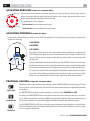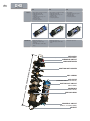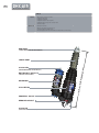
1
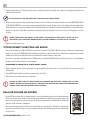
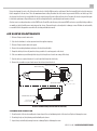
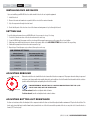
TABLE OF CONTENTS
QUICK REFERENCE / WARRANTY INFO / MAINTENANCE SCHEDULE . . . . . . . . . . . . . . 2
CONSUMER SAFETY . . . . . . . . . . . . . . . . . . . . . . . . . . . . . . . . . . . . . . . . . . . 4
IMPORTANT SAFETY INFORMATION . . . . . . . . . . . . . . . . . . . . . . . . . . . . . . . . . . 4
GENERAL MAINTENANCE . . . . . . . . . . . . . . . . . . . . . . . . . . . . . . . . . . . . . . . . 5
MEASURING SAG . . . . . . . . . . . . . . . . . . . . . . . . . . . . . . . . . . . . . . . . . . . . . 5
USING THE FOX HIGH PRESSURE PUMP . . . . . . . . . . . . . . . . . . . . . . . . . . . . . . . . 5
“STUCK DOWN” FLOAT/DHX AIR SHOCK . . . . . . . . . . . . . . . . . . . . . . . . . . . . . . . 6
AVA (AIR VOLUME ADJUSTER) . . . . . . . . . . . . . . . . . . . . . . . . . . . . . . . . . . . . . 6
AIR SLEEVE MAINTENANCE . . . . . . . . . . . . . . . . . . . . . . . . . . . . . . . . . . . . . . . 7
REDUCER REMOVAL . . . . . . . . . . . . . . . . . . . . . . . . . . . . . . . . . . . . . . . . . . . 8
FLOAT . . . . . 9
INSTALLING FLOAT SHOX (ALL FLOAT MODELS). . . . . . . . . . . . . . . . . . . . . . . . . . 10
SETTING SAG (ALL FLOAT MODELS) . . . . . . . . . . . . . . . . . . . . . . . . . . . . . . . . . 10
ADJUSTING REBOUND (FLOAT RP3 & FLOAT R ONLY). . . . . . . . . . . . . . . . . . . . . . . . 11
ADJUSTING PROPEDAL (FLOAT RP3 ONLY) . . . . . . . . . . . . . . . . . . . . . . . . . . . . . . 11
PROPEDAL VALVING (FLOAT RP3 & FLOAT R ONLY) . . . . . . . . . . . . . . . . . . . . . . . . . 11
DHX . . . . . . 12
INSTALLING DHX SHOX (DHX 5.0, 4.0 & 3.0) . . . . . . . . . . . . . . . . . . . . . . . . . . . . 13
SETTING SAG (DHX 5.0, 4.0 & 3.0) . . . . . . . . . . . . . . . . . . . . . . . . . . . . . . . . . . 13
CHANGING SPRINGS (DHX 5.0, 4.0 & 3.0) . . . . . . . . . . . . . . . . . . . . . . . . . . . . . . 14
SPRING ORIENTATION . . . . . . . . . . . . . . . . . . . . . . . . . . . . . . . . . . . . . . . . . 14
ADJUSTING REBOUND (DHX 5.0, 4.0 & 3.0) . . . . . . . . . . . . . . . . . . . . . . . . . . . . . 14
ADJUSTING BOTTOM-OUT RESISTANCE (DHX 5.0 ONLY). . . . . . . . . . . . . . . . . . . . . 14
ADJUSTING PROPEDAL (DHX 5.0. & 4.0 ONLY) . . . . . . . . . . . . . . . . . . . . . . . . . . . 15
BOOST VALVE . . . . . . . . . . . . . . . . . . . . . . . . . . . . . . . . . . . . . . . . . . . . . . 15
PROPEDAL AND BOOST VALVE INTERACTION (DHX 5.0. & 4.0 ONLY) . . . . . . . . . . . . . 15
DHX AIR. . . .16
INSTALLING DHX AIR SHOCK . . . . . . . . . . . . . . . . . . . . . . . . . . . . . . . . . . . . . 17
SETTING SAG. . . . . . . . . . . . . . . . . . . . . . . . . . . . . . . . . . . . . . . . . . . . . . . 17
ADJUSTING REBOUND . . . . . . . . . . . . . . . . . . . . . . . . . . . . . . . . . . . . . . . . . 17
ADJUSTING BOTTOM-OUT RESISTANCE . . . . . . . . . . . . . . . . . . . . . . . . . . . . . . . 17
ADJUSTING PROPEDAL. . . . . . . . . . . . . . . . . . . . . . . . . . . . . . . . . . . . . . . . . 18
BOOST VALVE . . . . . . . . . . . . . . . . . . . . . . . . . . . . . . . . . . . . . . . . . . . . . . 18
PROPEDAL AND BOOST VALVE INTERACTION . . . . . . . . . . . . . . . . . . . . . . . . . . . 18
VANILLA . . .19
INSTALLING VANILLA SHOX . . . . . . . . . . . . . . . . . . . . . . . . . . . . . . . . . . . . . . 20
SETTING SAG. . . . . . . . . . . . . . . . . . . . . . . . . . . . . . . . . . . . . . . . . . . . . . . 20
ADJUSTING REBOUND (VANILLA R ONLY) . . . . . . . . . . . . . . . . . . . . . . . . . . . . . 21
CHANGING SPRINGS (ALL VANILLA MODELS) . . . . . . . . . . . . . . . . . . . . . . . . . . . 21
INTERNATIONAL VERSIONS
FRANCAIS . . . . . . . . . . . . . . . . . . . . . . . . . . . . . . . . . . . . . . . . . . . . . . . . 22
ITALIANO . . . . . . . . . . . . . . . . . . . . . . . . . . . . . . . . . . . . . . . . . . . . . . . . . 42
DEUTSCH . . . . . . . . . . . . . . . . . . . . . . . . . . . . . . . . . . . . . . . . . . . . . . . . . 62
ESPANOL . . . . . . . . . . . . . . . . . . . . . . . . . . . . . . . . . . . . . . . . . . . . . . . . . 82
. . . . . . . . . . . . . . . . . . . . . . . . . . . . . . . . . . . . . . . . . . . . . . . . . . .102
INTERNATIONAL SERVICE CENTERS . . . . . . . . . . . . . . . . . . . . . . 122
DENOTES INFORMATION THAT MAY NOT BE OBVIOUS, OR THAT CAN HELP THE RIDER OUT WITH A DIFFICULT SITUATION.
DENOTES INFORMATION THAT, IF NOT FOLLOWED, CAN LEAD TO SERIOUS INJURY OR DEATH, OR CAUSE SERIOUS DAMAGE TO YOUR FORK.
4
CONGRATULATIONS!
Thank you for choosing FOX SHOX for your bicycle. In doing so, you have chosen the finest suspension shock in the world. FOX Racing Shox products are
designed, tested and manufactured by the finest professionals in the industry in Santa Cruz County, California, USA.
As a consumer and supporter of FOX Racing Shox products, you need to be aware of the importance of setting up your shock correctly to ensure maximum
performance. This manual provides step-by-step instructions of how to setup and maintain your shock. It is a good idea to keep your receipts with this
manual, and refer to it for service and warranty issues.
For detailed service instructions, consult a FOX Service Manual for your particular product. This manual does not contain step-by-step detailed service
instructions for a reason: FOX recommends that detailed service be performed by an Authorized Service Center or FOX Racing Shox.
CONSUMER SAFETY
> Keep your bicycle and suspension system in optimal working condition.
> Wear protective clothing, eye protection and always fasten your helmet before you ride.
> Know and ride within your limits.
> Follow IMBA's Rules of the Trail. For more information, go to www.imba.com:
1. Ride on open trails only
2. Leave no trace
3. Control your bicycle
4. Always yield trail
5. Never scare animals
6. Plan ahead
IMPORTANT SAFETY INFORMATION
> If the shock ever loses oil or makes unusual noises, stop riding and have the shock inspected by qualified personnel. A broken or malfunctioning shock
can result in loss of control and possible serious or fatal injuries.
> Do not modify your bike frame or shock. Use only genuine FOX Racing Shox parts. Modification, improper service or use of aftermarket replacement
parts voids the warranty and could cause the shock to malfunction, and can cause loss of control resulting in serious injury or death.
> Follow the scheduled maintenance recommendations listed on the inside cover of this manual. Shock service should be performed by FOX Racing Shox
in the USA or an Authorized Service Center outside the USA. The exception is air sleeve and mounting hardware service and maintenance, which can
be performed by the consumer or retailer.
> FOX Racing Shox contain a nitrogen charge. Do not pry out the white nylon (plastic) plug at the eyelet end of the shock. The charged portion of the
shock should only be opened by a FOX Racing Shox technician. Opening a nitrogen pressurized shock can be dangerous and can result in serious injury
or death.
> On air shocks, the portion of the shock charged with nitrogen does not need to be opened to perform air sleeve service.
DO NOT ATTEMPT TO PULL APART, OPEN, DISASSEMBLE OR SERVICE A SHOCK IF IT IS
COMPRESSED OR HAS NOT RETURNED (WILL NOT RETURN) TO ITS ORIGINAL NEUTRAL LENGTH
(WITH NO LOAD ON THE SHOCK). THIS CAN RESULT IN SERIOUS OR FATAL INJURIES.
2006 REAR SHOCK OWNER’S MANUAL | P/N: 605-00-048
5
GENERAL MAINTENANCE
On FLOAT and DHX AIR shocks there may be a small amount of air sleeve lubricant residue on the body. This is normal. If this residual air sleeve lubricant
is not present, this is an indication that the air sleeve should be re-lubricated. Some other things to consider for all shock models:
> If you ride in extreme conditions, service your shock and air sleeve more frequently. See the maintenance schedule on the inside cover of this
manual.
> Wash your shock with soap and water only.
> Do not use a high pressure washer to clean your shock.
> Extensive internal service should be performed by FOX Racing Shox or an Authorized FOX Racing Shox Service Center.
MEASURING SAG
Use this procedure to measure the sag on your FOX Racing Shox:
MEASUREMENT #1
1. Before sitting on the bicycle, measure and record the distance from the center of one mounting bolt to the center of the other mounting bolt. This
is known as the “eye-to-eye” measurement.
Air shocks have an o-ring on the shock body. The o-ring should be pushed up against the scraper lip of the air sleeve without the rider on the bike.
If there is no o-ring, use the "eye-to-eye" method.
MEASUREMENT #2
2. Sit on the bicycle in a normal riding position. Your weight should be distributed on the saddle, handlebars and pedals. It is also recommended that
you be outfitted in your normal riding gear. It may be necessary to hold yourself up against a wall or post to steady yourself. Do not bounce on the
pedals or saddle.
3. Have an assistant measure and record the eye-to-eye distance.
For an air shock, dismount the bicycle and measure from the scraper lip to the o-ring. This is the sag, using the o-ring method.
4. Subtract measurement #2 from measurement #1. The difference between the two is sag.
MEASUREMENT #1 – MEASUREMENT #2 = SAG
(E.G.: 7.875 - 7.275 = .600)
5. Consult the air or spring settings table in your respective shock’s section in this manual. If the sag specifications not in compliance, follow the instructions in SETTING SAG in the respective shock’s section.
USING THE FOX HIGH PRESSURE PUMP
A FOX Racing Shox High Pressure Air Pump is available for your FLOAT, DHX or DHX AIR shock.
The pump is used to add and release air pressure from your shock.
To pressurize your shock:
1. Remove the Schrader air valve cap from the shock.
FOX High Pressure Pump
2. Thread the pump’s valve chuck onto the shock’s air valve until pressure registers on the pump
gauge. This takes approximately 6 turns. Do not over-tighten the pump on air valve as this will damage the pump chuck seal.
P/N: 605-00-048 | 2006 REAR SHOCK OWNER’S MANUAL
6
3. Stroke the pump a few cycles. The pressure should increase slowly. If pressure increases rapidly check to make sure the pump is properly fitted and
tightened onto the air valve.
IF THE SHOCK HAS NO AIR PRESSURE, THE GAUGE WILL READ ZERO.
4. Pump to the desired pressure setting. Average air pressure range is from 50 to 300 psi for the main air chamber on air shocks. DO NOT EXCEED 300 PSI
IN THE MAIN AIR CHAMBER. You can decrease pressure by pushing the black bleed valve. Pushing the bleed valve half way down and holding it there
will allow pressure to escape from the pump and shock. Pushing the bleed valve all the way down and releasing it will allow only a small amount of
pressure to escape (micro adjust). When unthreading the pump from the air valve fitting, the sound of the air loss is from the pump hose, not from
the shock.
WHEN YOU ATTACH THE PUMP TO THE SHOCK, THE HOSE WILL NEED TO FILL WITH AIR. THIS
MAY RESULT IN A PRESSURE READING THAT CAN BE LOWER BY AS MUCH AS 10 TO 20 PSI.
5. Replace the Schrader air valve cap.
“STUCK DOWN” FLOAT/DHX AIR SHOCK
Under certain circumstances, a FLOAT or DHX AIR shock can become "stuck down.” If your FLOAT or DHX AIR shock has not returned to its original neutral
length (eye-to-eye position), DO NOT attempt to disassemble the outer air sleeve or any other part of the shock. Air has become trapped in the air negative
chamber and can cause serious injury if the shock is disassembled. This condition is known as “stuck down.”
If your shock is “stuck down,” immediately return it to FOX Racing Shox or an Authorized FOX Racing Shox Service Center for service. Service and warranty
information can be found on the inside cover of this manual.
PROCEDURE TO CHECK FOR A “STUCK DOWN” SHOCK:
1. Release air pressure from the shock by removing the air cap and depressing the Schrader valve. You can use the top of the air cap to press in the
Schrader valve.
2. Using a FOX Racing Shox High Pressure Pump, pressurize the shock to 250 psi.
3. If the shock does not extend, it has become “stuck down.”
DO NOT ATTEMPT TO PULL APART, OPEN, DISASSEMBLE OR SERVICE A SHOCK THAT IS STUCK
DOWN. SERIOUS INJURY CAN RESULT. CONTACT FOX RACING SHOX OR AN AUTHORIZED FOX
RACING SHOX SERVICE CENTER FOR ASSISTANCE.
AVA (AIR VOLUME ADJUSTER)
Certain FLOAT models feature AVA (see diagram at right), a technology that affords new levels of fine-tuning adjustment.
AVA increases or decreases the volume of the positive air spring chamber, which allows the rider to alter the shape of the
spring curve. The AVA system can create a shock with a 30% more linear spring rate than a standard FLOAT shock. AVA allows
as much as 200 lbs. of bottom-out adjustment.
AVA is a pre-ride tuning feature. The AVA system is not intended to be used on-the-fly. It is important to clean your shock,
especially the threads of the AVA air sleeve, prior to adjustment. Rotation of the AVA ring may require near complete deflation of the shock.
2006 REAR SHOCK OWNER’S MANUAL | P/N: 605-00-048
AVA Air Sleeve
7
Using a shock pump, let most or all of the air from the shock so that the AVA ring can be easily turned. Turn the ring until it just touches the wire ring
that is snapped onto the air sleeve. This is the maximum volume setting. Pressurize the shock and set sag as normal. AVA does not affect sag. If the
shock seems to bottom out too easily, deflate the shock, rotate the ring to the next setting on the air sleeve. Pressurize the shock, set sag and test again
for full stroke performance. Repeat this process until the setting that best fits your riding style and terrain is achieved.
Air sleeve service can be performed as on other FLOAT shocks. Clean AVA seals after every other normal FLOAT seal service, especially if riding conditions
are muddy or dusty. Carefully remove wire rings and air sleeves. Clean and inspect seals and parts for damage or wear. Re-lubricate and carefully
re-assemble. Refer to diagram for areas with critical sealing and lubrication needs.
AIR SLEEVE MAINTENANCE
1. Release all air pressure from air valve.
2. Cycle shock a few times to release pressure from the negative air spring.
3. Release all air pressure from air valve again.
4. Remove the mounting hardware and remove the shock from the bike.
5. Clamp the shaft eyelet in a soft-jawed vice being careful not to crush any parts on the shock.
6. Slide a screwdriver or punch through the body eyelet to keep the air sleeve from coming off the body.
7. Turn the air sleeve counterclockwise to loosen it and slide it down the shock body.
8. Remove the screwdriver or punch and remove the air sleeve from the shock.
THREADS FOR AIR SLEEVE
GREASE LIGHTLY HERE
SHAFT
AIR VALVE
GREASE LIGHTLY HERE
SHAFT EYELET O-RING
GREASE BEARINGS, SEAL & WIPER
AIR SLEEVE WIPER
AIR SLEEVE BEARING
AIR SLEEVE BEARING
AIR SLEEVE SEAL
Air Sleeve: Orientation and position on FLOAT air shock body.
CLEANING AND INSPECTION
1. Clean the inside of the air sleeve with parts cleaner. Inspect the seal and bearing inside of the air sleeve. Replace if damaged or worn.
2. Clean body, body seal, body bearings and shaft with parts cleaner.
3. Inspect body seal and body bearings for wear or damage. Replace if damaged or worn.
P/N: 605-00-048 | 2006 REAR SHOCK OWNER’S MANUAL
8
GREASING AND REASSEMBLING
1. Lubricate the shaft eyelet O-ring and shaft eyelet threads with FLOAT Fluid or Slick Honey™.
2. Liberally lube the body seal and body bearing, leaving a reservoir of lube above the body bearing .
3. Lubricate the air sleeve seal, air sleeve bearing, and air sleeve wiper. FLOAT Fluid can be used in this application.
4. Slide the air sleeve over the body until the air sleeve wiper is at the end of the body. Leave the air sleeve unthreaded at this time.
THE AIR SLEEVE WILL BE VERY DIFFICULT TO COMPRESS BECAUSE THERE IS PRESSURE
TRAPPED IN THE NEGATIVE AIR CHAMBER. WAITING UNTIL AFTER THE SHOCK IS MOUNTED
IN THE BIKE WILL ALLOW THE LEVERAGE OF THE BIKE TO EASILY COMPRESS THE SHOCK.
5. Dry bushings and reducers.
6. Install reducers in eyelet bushings and install the shock back on the bike.
7. Carefully compress the shock until you can screw on the air sleeve. Don't let the air sleeve slip off the body.
8. Thread the air sleeve onto shaft eyelet hand tight.
9. Inflate shock using inflation instructions listed in the Pump Instructions.
REDUCER REMOVAL
1. Screw a 3/8” bolt extractor (see picture below) counterclockwise with a pulling motion. The reducer will back out of the bushing.
2. Repeat for the other side.
3. Insert a stainless steel sleeve into the shock’s bushing, and place the shock eyelet into a soft-jaw vise.
4. Turn the vise handle so that the sleeve is driven in to the bushing. Once the sleeve is pushed into the other side, turn the shock body up and down
to slide the shock eyelet to the center of the sleeve.
5. Take the shock out of the vise and place aluminum sleeve spacers on each side.
6. Reload shock eyelet into the vise and turn handle up and down for final centering.
1/4” Bolt Extractor Tool
2006 REAR SHOCK OWNER’S MANUAL | P/N: 605-00-048
Inserting Bolt Extractor Tool Into Reducer
Centering Aluminum Hardware on Vise
FLOAT
features
adjustments
FLOAT RP3
FLOAT R
FLOAT
> Adjustable ProPedal
> Adjustable air spring
> Adjustable rebound
> Adjustable air spring
> Adjustable rebound
> Adjustable air spring
> Rebound: red knob
> ProPedal adjust: blue lever
> Air spring adjust: via Schrader
valve
> Rebound: red knob
> Air spring adjust: via Schrader
valve
> Air spring adjust: via Schrader
valve
REBOUND ADJUST
(RP3 & R MODEL ONLY)
PROPEDAL LEVER
(RP3 MODEL ONLY)
AIR VALVE & CAP
(SCHRADER VALVE)
SHOCK BODY
BODY EYELET
(EYE-T
O-EYE)
TRAVEL INDICATOR O-RING
SHOCK
LENGT
H
AIR SLEEVE
9
FLOAT
10
DHX
DHX AIR
INSTALLING FLOAT SHOX (ALL FLOAT MODELS)
If you are installing your FLOAT shock on a bike in which the shock is not original equipment:
1. Install the shock.
2. Remove the air cap and let all the air out of the air chamber.
3. Cycle the suspension through its entire travel.
4. Check that all parts of the shock are clear of the frame and swingarm as it cycles through the travel.
SETTING SAG (ALL FLOAT MODELS)
To get the best performance from your FLOAT shock, it is necessary to set sag. For initial sag measurement, see MEASURING SAG on page 5.
To set sag:
1. Locate the Schrader air valve on the shock and remove the valve cap.
2. Screw the FOX Racing Shox pump onto the air valve until the pump shows pressure on the gauge. Do not over-tighten.
3. Add air pressure until desired pressure is shown on the gauge. Refer to the AIR SPRING SETTINGS table below for the sag setting.
4. Unthread the pump from the air valve and measure the sag.
5. Repeat steps 2-4 until proper sag is achieved, then replace valve cap.
AIR SPRING SETTINGS
Shock Travel
Inches/Millimeters
Recommended Sag
Inches/Millimeters
1.00/25.4
.25/6.4
1.25/31.7
.31/7.9
1.50/38.1
.38/9.5
1.75/44.4
.44/11.1
2.00/50.8
.50/12.7
2.25/57.1
.56/14.2
2.50/63.5
.62/15.7
3.00/76.2
.75/19.1
2006 REAR SHOCK OWNER’S MANUAL | P/N: 605-00-048
VANILLA
FLOAT
DHX
DHX AIR
VANILLA
11
ADJUSTING REBOUND (FLOAT RP3 & FLOAT R ONLY)
Rebound controls the rate at which the shock returns after it has been compressed. The proper rebound setting is a personal
preference, and changes with rider weight, riding style and conditions. A rule of thumb is that rebound should be as fast as
possible without kicking back and pushing the rider off the saddle.
Slower (CW)
The rebound knob has 9 clicks of adjustment.
For slower rebound, turn the red adjuster knob clockwise.
Faster (CCW)
For faster rebound, turn the red adjuster knob counterclockwise.
ADJUSTING PROPEDAL (FLOAT RP3 ONLY)
The three-position ProPedal tuning lever allows for on-the-fly ProPedal adjustment. ProPedal damping reduces pedal-induced suspension bob.
The three lever settings are:
1. LIGHT PROPEDAL
TRAL ZONE
NEU
2. MID PROPEDAL
3. FULL PROPEDAL
+
Use the different settings to tune the shock to different riding conditions and situations. For example, use the
Full ProPedal position for riding to the top of the mountain and then switch to the Light ProPedal position for
the descent. Because suspension designs and riding skills vary, optimal settings can vary from bike to bike
and rider to rider.
-
3
1
2
To determine which ProPedal position is best, pedal the bicycle at about 15 MPH and monitor the shock movement.
Switch between positions and select the one that reduces suspension movement most effectively while providing
the desired amount of bump absorption. The setting may change depending on conditions and riding styles.
The “neutral zone” between the Full ProPedal and Light ProPedal adjustments is simply a transition zone between
the two settings. However, FOX recommends that the lever not be left in the “neutral zone” as there is no detent,
and the lever can accidentally shift into the Full ProPedal or Light ProPedal settings during hard riding.
PROPEDAL VALVING (FLOAT RP3 & FLOAT R ONLY)
Light ProPedal
Medium ProPedal
Firm ProPedal
FOX Racing Shox and your bike manufacturer have teamed up to deliver a FLOAT RP3/FLOAT R shock that has the perfect ProPedal
tune for your bicycle’s rear suspension design. This internal ProPedal valving is separate from the user-adjustable ProPedal tuning
described above.
Your FLOAT RP3/FLOAT R is delivered to your bike manufacturer in one of three settings: FIRM, MEDIUM, and LIGHT.
The setting of your FLOAT RP3/FLOAT R is listed on the band at the bottom of the air sleeve and is denoted by an icon, as shown on
the left. LIGHT is represented by the smallest bar. MEDIUM is represented by the middle bar. FIRM is represented by the largest
bar. The bar that is applicable to your tune will be highlighted and flanked on top and bottom with indicator arrows.
Your 2006 FLOAT RP3/FLOAT R has FOX’s latest cutting edge compression damping technology that delivers our best performing
FLOAT shock ProPedal performance yet. Changing your ProPedal tune can be done at an Authorized FOX Service Center for a charge
as it is not considered a warranty item.
P/N: 605-00-048 | 2006 REAR SHOCK OWNER’S MANUAL
DHX
features
adjustments
5.0
4.0
3.0
> Boost Valve / Position sensitive
> Adjustable ProPedal
> Adjustable bottom-out
resistance
> Adjustable tuning range via
Schrader valve
> Rebound adjust
> Coil spring preload
> Boost Valve / Position sensitive
> Adjustable ProPedal
> Adjustable tuning range via
Schrader valve
> Rebound adjust
> Coil spring preload
> Boost Valve
> Adjustable tuning range via
Schrader valve
> Rebound adjust
> Coil spring preload
> Rebound: red knob
> Bottom-out adjust: large
blue dial
> ProPedal adjust: smaller blue
knob
> Rebound: red knob
> ProPedal adjust: smaller blue
knob
> Rebound: red knob
REDUCERS
(VARIES DEPENDING ON BIKE MODEL)
-EYE
)
REBOUND ADJUST
SPRING RETAINER
SHOC
K LEN
GTH
(EYE
-TO
12
BOTTOM-OUT BUMPER
COIL SPRING
AIR VALVE
(RESERVOIR BOOST VALVE ADJUST)
BOTTOM-OUT ADJUST
(DHX 5.0 ONLY)
RESERVOIR
(WITH BOOST VALVE)
PRELOAD RING
PROPEDAL ADJUST
(DHX 5.0, 4.0 & AIR 5.0 ONLY)
EYELET
FLOAT
DHX
DHX AIR
VANILLA
13
INSTALLING DHX SHOX (DHX 5.0, 4.0 & 3.0)
If you are installing your DHX shock on a bike in which the shock is not original equipment:
1. Install the shock with the spring retainer, but without the spring. (To remove the spring, perform steps 1 – 3 in CHANGING SPRINGS on page 14.)
2. Carefully cycle the suspension through its entire travel.
3. Check that all parts of the shock are clear of the frame and swingarm as it cycles through the travel.
4. Properly place the spring back onto the shock. (To install the spring, perform steps 4 – 7 in CHANGING SPRINGS on page 14.)
5. Set sag as described in the next section, SETTING SAG.
SETTING SAG (DHX 5.0, 4.0 & 3.0)
Setting sag is necessary is to obtain the best performance from your DHX shock. To set sag:
1. Measure sag as described in MEASURING SAG on page 5, and compare it to the recommended sag setting shown in the COIL SPRING SETTINGS table
below.
2. Adjust the preload ring accordingly:
If sag is lower than on the table, turn the preload ring counterclockwise. Always ensure that the spring is secure and does not freely move.
AFTER THE PRELOAD RING ENGAGES THE SPRING, TURN THE PRELOAD RING CLOCKWISE ONE
TURN. IF THE PRELOAD RING NEEDS TO TURNED COUNTERCLOCKWISE FROM THIS POINT TO
ACHIEVE PROPER SAG, YOU WILL NEED TO OBTAIN A LOWER RATE SPRING.
If sag is higher than on the table, turn the preload ring clockwise no more than full two turns after the preload ring engages the spring.
IF AFTER THE PRELOAD RING ENGAGES THE
SPRING, MORE THAN 2 FULL CLOCKWISE TURNS
ARE REQUIRED TO ACHIEVE THE PROPER SAG
SETTING, YOU WILL NEED TO OBTAIN A HIGHER
RATE SPRING.
FOXS
HOX
3. If necessary, contact FOX Racing Shox or an Authorized Service Center to obtain
a higher- or lower-rated spring.
450 X
2
UP
COIL SPRING SETTINGS
Shock Travel
Inches/mm
Recommended Sag
Inches/mm
2.00/50.8
.50/12.7
2.25/57.1
.56/14.3
2.50/63.5
.63/15.9
2.75/69.6
.69/17.5
3.00/76.2
.76/19.0
.37
FOXSH
OX
450 X
2.37
The spring rate is printed directly on the shock spring. The
spring above has a 450-lb/in spring rate with 2.37” of travel.
P/N: 605-00-048 | 2006 REAR SHOCK OWNER’S MANUAL
FLOAT
14
DHX
DHX AIR
VANILLA
CHANGING SPRINGS (DHX 5.0, 4.0 & 3.0)
1. Loosen the preload ring until the spring freely moves.
2. Lift up the spring and remove the spring retainer.
3. Slide the spring off the shock body. Depending on your bike model, you may need to remove the reducers to remove the spring.
4. Orient the new spring correctly (see SPRING ORIENTATION below) and slide it onto the shock body.
5. Place the spring retainer back on the shock and under the spring ensuring that the open slot on the spring retainer rests on the flat part of the spring
end.
6. Tighten the preload ring just until the spring no longer moves.
7. Turn the preload ring one additional full turn.
SPRING ORIENTATION
When placing the spring back on the shock body, it is important that the spring is correctly oriented. Essentially, the space in the spring retainer should
rest on the flat part of the spring, and not on the segment of the spring where it starts to coil back under itself. Rotate the spring or spring retainer until
the correct orientation is achieved.
An improperly oriented spring can fail prematurely, causing loss of control of the bicycle, which can result in serious or fatal injuries. The pictures below
demonstrate correct and incorrect spring orientation. Correct spring orientation applies to all FOX Racing Shox rear shocks that utilize coil springs:
INCORRECT
CORRECT
SPACE
NO SPACE
ADJUSTING REBOUND (DHX 5.0, 4.0 & 3.0)
EB
OU
N
S
R
D
R
Slower (CW)
Rebound controls the rate at which your shock returns after it has been compressed. The proper rebound setting is a personal
preference, and changes with rider weight, riding style and conditions. A rule of thumb is that rebound should be as fast as
possible without kicking back and pushing the rider off the saddle.
For slower rebound, turn the red adjuster knob clockwise.
For faster rebound, turn the red adjuster knob counterclockwise.
L OW E
Faster (CCW)
ADJUSTING BOTTOM-OUT RESISTANCE (DHX 5.0 ONLY)
Bottom-out resistance affects the final part of the compression stroke. Bottom-out should be adjusted with a maximum of 125 psi in the Boost Valve. The
knob can be turned by hand or with a 4mm hex key inserted into one of the holes around the perimeter. Do not use any other tool to turn the knob—a
4mm (5/32”) hex key only!
2006 REAR SHOCK OWNER’S MANUAL | P/N: 605-00-048
DHX
FLOAT
DHX AIR
VANILLA
15
Turn the knob all the way clockwise for the most bottom-out resistance and counter-clockwise for the least. There are three (3) rotations of adjustment
and three (3) corresponding Adjustment Indicator Lines on the reservoir.
T
Indicator
Lines
T OM O
U
T
BO
More
Resistance
+
-
Less
Resistance
IF THE KNOB FEELS GRITTY DURING
ROTATION, SET THE KNOB TO MAXIMUM
VOLUME AND THEN USE A 2MM (5/64”)
HEX KEY TO LOOSEN THE SET SCREWS IN
THE PERIMETER HOLES AND REMOVE THE
KNOB. CLEAN THE KNOB THOROUGHLY,
GREASE AND RE-INSTALL.
ADJUSTING PROPEDAL (DHX 5.0. & 4.0 ONLY)
The ProPedal adjustment knob allows the rider to adjust the amount of ProPedal damping. ProPedal damping affects the first part of the compression
stroke and is designed to control pedal-induced suspension bob. Since suspension designs vary, not all bicycles require the same degree of ProPedal
damping provided by the Boost Valve.
There are 15 clicks of adjustment. Rotate the knob all the way counter-clockwise for the lightest ProPedal setting and all the way clockwise for the most
ProPedal damping.
BOOST VALVE
+
Pe d
ro
al
P
More
Damping
-
Less
Damping
The Boost Valve creates a position-sensitive damping scheme that allows for a seamless transition from efficient ProPedal to
square-edge bump absorption to a bottomless end-of-stroke feel. The Boost Valve also decouples the ProPedal and bottom out
adjustments, enabling ProPedal platform adjustment to be made separately from the bottom out adjustment.
The Boost Valve is not adjusted directly. Instead, its behavior and performance characteristics are influenced by the air pressure
setting in the reservoir and by adjusting the ProPedal knob (DHX 5.0 & 4.0 only).
To change the compression damping characteristics of your DHX shock, attach a FOX High Pressure Pump (see USING THE FOX
HIGH PRESSURE PUMP on page 5) to the air valve on the reservoir:
For a firmer ride, add 10 – 15 pounds of air pressure.
For a softer ride, decrease the shock’s air pressure 10 – 15 pounds by using the pump’s bleed valve.
Ride your bike and verify the settings before repeating the procedure.
NEVER RIDE YOUR BIKE WITH MORE THAN 200 PSI OR LESS THAN 75 PSI IN THE RESERVOIR
AIR CHAMBER. DOING SO WILL DAMAGE YOUR SHOCK AND REQUIRE REPAIRS THAT ARE NOT
COVERED UNDER WARRANTY.
PROPEDAL AND BOOST VALVE INTERACTION (DHX 5.0. & 4.0 ONLY)
Certain aspects of the Boost Valve can influence the ProPedal adjustment. If the ProPedal adjustment knob is fully counterclockwise (lightest ProPedal
damping position) and the compression damping is still too strong, attach a shock pump to the Schrader valve on the reservoir and reduce the pressure
10 – 15 psi. Repeat to achieve the desired compression damping. If there is not enough compression damping with the ProPedal knob fully clockwise, add
10 – 15 psi to the Boost Valve until desired compression damping is achieved.
P/N: 605-00-048 | 2006 REAR SHOCK OWNER’S MANUAL
16
DHX AIR
AIR 5.0
features
>
>
>
>
>
>
Boost Valve / Position sensitive
Adjustable air spring
Adjustable ProPedal
Adjustable bottom-out resistance
Adjustable tuning range via Schrader valve
Rebound adjust
adjustments
>
>
>
>
Rebound: red knob
Bottom-out adjust: large blue knob
ProPedal adjust: small blue knob
Air spring adjust: via main air chamber Schrader valve on lower body
REDUCERS
(VARIES DEPENDING ON BIKE MODEL)
SHOCK BODY
SHOC
K
AIR VALVE
(RESERVOIR BOOST VALVE ADJUST)
BOTTOM-OUT ADJUST
RESERVOIR
E)
E-TO
-EY
AIR SLEEVE
LENG
TH (E
Y
(HEX-KEY ADJUSTABLE)
PROPEDAL ADJUST
REBOUND ADJUST
AIR VALVE
(MAIN AIR CHAMBER ADJUST)
FLOAT
DHX
DHX AIR
VANILLA
17
INSTALLING DHX AIR SHOCK
If you are installing your DHX AIR shock on a bike in which the shock is not original equipment:
1. Install the shock.
2. Remove the main air chamber air cap and let all the air out of the main air chamber.
3. Cycle the suspension through its entire travel.
4. Check that all parts of the shock are clear of the frame and swingarm as it cycles through the travel.
SETTING SAG
To get the best performance from your DHX AIR shock, it is necessary to set sag. To set sag:
1. Locate the Schrader air valve on the shock and remove the valve cap.
2. Screw the FOX Racing Shox pump onto the air valve until the pump shows pressure on the gauge. Do not over-tighten.
3. Add air pressure until desired pressure is shown on the gauge. Refer to the AIR SPRING SETTINGS table below for the sag setting.
4. Unthread the pump from the air valve and measure the sag.
5. Repeat steps 2-4 until proper sag is achieved, then replace valve cap.
AIR SPRING SETTINGS
Shock Travel
Inches/Millimeters
Recommended Sag
Inches/Millimeters
2.00/50.8
.25/6.3
2.25/57.2
.56/14.2
2.50/63.5
.62/15.7
3.00/76.2
.75/19
ADJUSTING REBOUND
Slower (CW)
Rebound controls the rate at which the shock returns after it has been compressed. The proper rebound setting is a personal
preference, and changes with rider weight, riding style and conditions. A rule of thumb is that rebound should be as fast as
possible without kicking back and pushing the rider off the saddle.
FOR REFERENCE, DIRECTION IS LOOKING DOWN FROM THE TOP (AIR
VALVE CAP SIDE) OF THE RESERVOIR.
Faster (CCW)
For slower rebound, turn the red adjuster knob clockwise.
For faster rebound, turn the red adjuster knob counterclockwise.
ADJUSTING BOTTOM-OUT RESISTANCE
Bottom-out resistance affects the final part of the compression stroke. Bottom-out should be adjusted with a maximum of 125 psi in the Boost Valve. The
knob can be turned by hand or with a 4mm hex key inserted into one of the holes around the perimeter. Do not use any other tool to turn the knob—a
4mm (5/32”) hex key only!
P/N: 605-00-048 | 2006 REAR SHOCK OWNER’S MANUAL
FLOAT
18
DHX
DHX AIR
VANILLA
Turn the knob all the way clockwise for the most bottom-out resistance and counter-clockwise for the least. There are three (3) rotations of adjustment
and three (3) corresponding Adjustment Indicator Lines on the reservoir.
T
Indicator
Lines
T OM O
U
T
BO
More
Resistance
+
-
Less
Resistance
IF THE KNOB FEELS GRITTY DURING
ROTATION, SET THE KNOB TO MAXIMUM
VOLUME (FULL CCW) AND THEN USE
A 2MM (5/64”) HEX KEY TO LOOSEN
THE SET SCREWS IN THE PERIMETER
HOLES AND REMOVE THE KNOB.
CLEAN THOROUGHLY, GREASE AND
RE-INSTALL.
ADJUSTING PROPEDAL
+
r
o Pe d
al
P
More
Damping
-
The ProPedal adjustment knob allows the rider to adjust the amount of ProPedal damping. ProPedal damping affects the first
part of the compression stroke and is designed to control pedal-induced suspension bob. Since suspension designs vary, not
all bicycles require the same degree of ProPedal damping provided by the Boost Valve.
There are 15 clicks of adjustment. Rotate the knob all the way counter-clockwise for the lightest ProPedal setting and all the
way clockwise for the most ProPedal damping.
Less
Damping
BOOST VALVE
The Boost Valve creates a position-sensitive damping scheme that allows for a seamless transition from efficient ProPedal to square-edge bump absorption
to a bottomless end-of-stroke feel. The Boost Valve also decouples the ProPedal and bottom out adjustments, enabling ProPedal platform adjustment to
be made separately from the bottom out adjustment.
The Boost Valve is not adjusted directly. Instead, its behavior and performance characteristics are influenced by the air pressure setting in the reservoir
and by adjusting the ProPedal knob.
To change the compression damping characteristics of your DHX shock, attach a FOX High Pressure Pump (see USING THE FOX HIGH PRESSURE PUMP on
page 5) to the air valve on the reservoir:
For a firmer ride, add 10 – 15 pounds of air pressure.
For a softer ride, decrease the shock’s air pressure 10 – 15 pounds by using the pump’s bleed valve.
Ride your bike and verify the settings before repeating the procedure.
NEVER RIDE YOUR BIKE WITH MORE THAN 200 PSI OR LESS THAN 75 PSI IN THE RESERVOIR
AIR CHAMBER. DOING SO WILL DAMAGE YOUR SHOCK AND REQUIRE REPAIRS THAT ARE NOT
COVERED UNDER WARRANTY.
PROPEDAL AND BOOST VALVE INTERACTION
Certain aspects of the Boost Valve can influence the ProPedal adjustment. If the ProPedal adjustment knob is fully counterclockwise (lightest ProPedal
damping position) and the compression damping is still too strong, attach a shock pump to the Schrader valve on the reservoir and reduce the pressure
10 – 15 psi. Repeat to achieve the desired compression damping. If there is not enough compression damping with the ProPedal knob fully clockwise, add
10 – 15 psi to the Boost Valve until desired compression damping is achieved.
2006 REAR SHOCK OWNER’S MANUAL | P/N: 605-00-048
VANILLA
VANILLA
> ProPedal (factory set)
> Rebound adjust
> Coil spring preload
> Coil spring preload
> Rebound: red knob
> Preload: black preload ring
> Preload: black preload ring
NITROGEN CHARGE
PRELOAD RING
YE-TO-E
YE)
FACTORY SET.
DO NOT OPEN!
NGTH (E
adjustments
VANILLA R
SHOCK L
E
features
COIL SPRING
BOTTOM-OUT BUMPER
SPRING RETAINER
(NON-REMOVABLE)
REBOUND ADJUST
(VANILLA R ONLY)
19
FLOAT
20
DHX
DHX AIR
VANILLA
INSTALLING VANILLA SHOX
If you are installing your Vanilla shock on a bike in which the shock is not original equipment:
1. Install the shock without the spring. (To remove the spring, perform steps 1 – 3 in CHANGING SPRINGS on the next page.)
2. Carefully cycle the suspension through its entire travel.
3. Check that all parts of the shock are clear of the frame and swingarm as it cycles through its entire suspension travel.
4. Properly place the spring back onto the shock. (To install the spring, perform steps 4 – 7 in CHANGING SPRINGS on the next page.)
5. Set sag as described in the next section, SETTING SAG.
SETTING SAG
Setting sag is necessary is to obtain the best performance from your VANILLA shock. To set sag:
1. Measure sag as described in MEASURING SAG on page 5, and compare it to the recommended sag setting shown in the COIL SPRING SETTINGS table
below.
2. Adjust the preload ring accordingly:
If sag is lower than on the table, turn the preload ring counterclockwise. Always ensure that the spring is secure and does not freely move.
AFTER THE PRELOAD RING ENGAGES THE SPRING, TURN THE PRELOAD RING CLOCKWISE ONE
TURN. IF THE PRELOAD RING NEEDS TO TURNED COUNTERCLOCKWISE FROM THIS POINT TO
ACHIEVE PROPER SAG, YOU WILL NEED TO OBTAIN A LOWER RATE SPRING.
If sag is higher than on the table, turn the preload ring clockwise no more than full two turns after the preload ring engages the spring.
IF AFTER THE PRELOAD RING ENGAGES THE SPRING, MORE THAN 2 FULL CLOCKWISE TURNS
ARE REQUIRED TO ACHIEVE THE PROPER SAG SETTING, YOU WILL NEED TO OBTAIN A HIGHER
RATE SPRING.
3. If necessary, contact FOX Racing Shox or an Authorized Service Center to obtain
a higher- or lower-rated spring.
COIL SPRING SETTINGS
Shock Travel
Inches/Millimeters
Recommended Sag
Inches/Millimeters
1.00/25.4
.25/6.4
1.25/31.7
.31/7.9
1.50/38.1
.38/9.5
1.75/44.4
.44/11.1
2.00/50.8
.50/12.7
2.25/57.1
.56/14.3
2.50/63.5
.63/15.9
2006 REAR SHOCK OWNER’S MANUAL | P/N: 605-00-048
FOX 35
0x2.8
0
The spring rate is printed directly on the shock spring. The rate
above denotes a 350-lb/in spring rate with 2.80” of travel.
DHX
FLOAT
DHX AIR
VANILLA
21
ADJUSTING REBOUND (VANILLA R ONLY)
EB
OU
N
Rebound controls the rate at which the shock returns after it has been compressed. The proper rebound setting is a person
preference, and changes with rider weight, riding style and conditions. A rule of thumb is that rebound should be as fast as
possible without kicking back and pushing the rider off the saddle.
S
R
D
R
Slower (CW)
For slower rebound, turn the red adjuster knob clockwise.
Faster (CCW)
For faster rebound, turn the red adjuster knob counterclockwise.
L OW E
CHANGING SPRINGS (ALL VANILLA MODELS)
1. Loosen the preload ring until the spring freely moves.
2. Lift up the spring and remove the spring retainer.
3. Slide the spring off the shock body. Depending on your bike model, you may need to remove the reducers to remove the spring.
4. Orient the new spring correctly (see SPRING ORIENTATION on page 14) and slide it onto the shock body.
5. Place the spring retainer back on the shock and under the spring.
6. Tighten the preload ring just until the spring no longer moves.
7. Turn the preload ring one additional full turn.
P/N: 605-00-048 | 2006 REAR SHOCK OWNER’S MANUAL