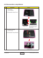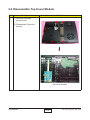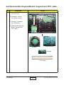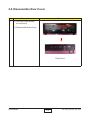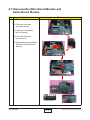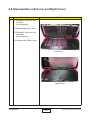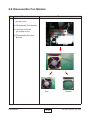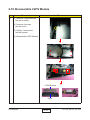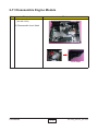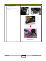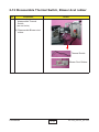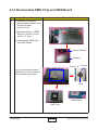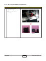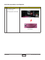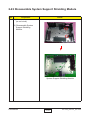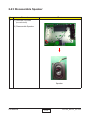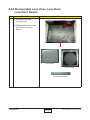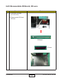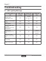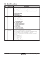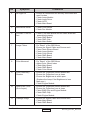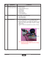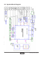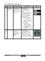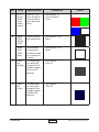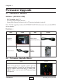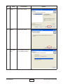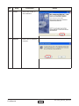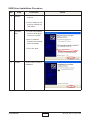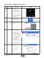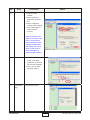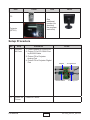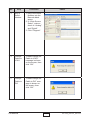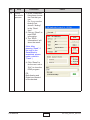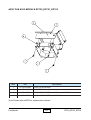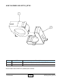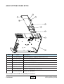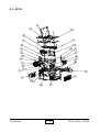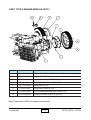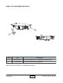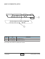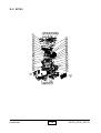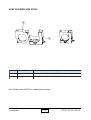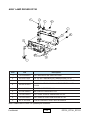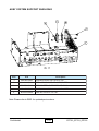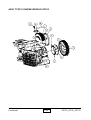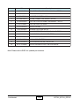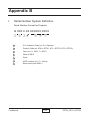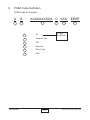
1
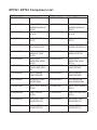
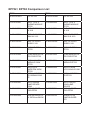
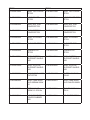
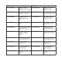
SERVICE MANUAL
Model Name : EP752_EP761_EP763
Prepared by SI :
________________________________________
Prepared by TSE :
________________________________________
Check by :
________________________________________
Approved by :
________________________________________
Date
Revise Version
Description
2007/6/20
V1.0
2007/7/6
V2.0
Add Appendix A and Appendix B
2007/8/8
V3.0
Add EP763
2007/11/7
V4.0
Modify Appendix B
Initial Issue
Copyright November, 2007. All Rights Reserved P/N: 36.87M03G001
95.87M01GC0A; 95.87M01G00A; 95.87J01GC0A; 95.87J01G00A; 95.87S01GC0A;95.87
S01GC01;95.87S01GC0B;95.87S01GC0C;95.87S01GC0E;95.87S01GC0H;95.87S01GC
0J;95.87S01GC0K;95.87S01GC0L;95.87S01GC0T;95.87S01GK0C;
EP752 / EP761 Comparison List
EP752
DC.87J01G001
70.87J01G001
D.C. EP752
EP761
DC.87M01G001
D.C. EP761
ASSY TYPE X
ENGINE MODULE
EP752
DMD HEATSINK3
AL X19
70.87M01G001
70.87J02G001
ASSY MB PCBA
EP752
70.87M02G001
80.87J01G002
PCBA MAIN BD EN- 80.87M01G003
TEK FOR EP752
PCBA MAIN BD2
ENTEK FOR EP761
70.87K03G001
ASSY X19 LVPS
MODULE 230W
EP752
ASSY LVPS
MATRITEK 200W
EP752
OSRAM O3 MID
200W LAMP DRIVER
ASSY OSRAM
LAMP DRIVER
70.87M03G001
ASSY X19 LVPS
MODULE EP761
75.87M01G001
ASSY LVPS
MATRITEK 230W
EP761
PHILIPS VIDI 220W
LAMP DRIVER
75.87W01G001
ASSY PHILIPS
LAMP DRIVER
39.87J03G001
OSRAM 6S W42
WAVEFORM
39.87M03G001
FW PHILIPS 6S
W42 WAVEFORM
70.87K07G001
ASSY TOP COVER
EP752
70.87M07G001
ASSY TOP COVER
EP761
51.87K22G001
LAMP COVER
EP752
51.87K22G011
LAMP COVER FOR
EP761
70.87K08G001
ASSY BOTTOM
COVER EP752
70.87M05G001
ASSY BOTTOM
COVER EP761
75.87K05G001
ASSY BOTTOM
COVER EP752
75.87M04G001
ASSY BOTTOM
COVER EP761
61.86V24G001
75.87J01G001
70.87U06G001
75.87J04G001
61.86V21G001
70.87W09G001
ASSY TYPE X
ENGINE MODULE
EP761
DMD HEATSINK2
AL X19
ASSY MB PCBA
EP761
EP752
70.87K09G001
ASSY IO COVER
EP752
EP761
70.87M06G001
ASSY IO COVER
EP761
51.87K19G001
IO COVER EP752
51.87K19G011
IO COVER FOR
EP761
51.87K24G001
OVERLAY PC
EP752
51.87M05G001
OVERLAY PC
EP761
70.86V08G001
ASSY LAMP MODULE OSRAM 200W
X1
OSRAM P-VIP
200W/1.0 E20.6n
70.86V09G001
ASSY LAMP MODULE PHILIPS 220W
23.87M15G001
LAMP MODULE
220W 1.0 E20.6 PHI
23.87J15G001
52.83F12G001
LAMP RUBBER
HD72
61.83F12G001
LAMP CLAMP
61.86V18G001
SUS301 t=0.3 HD72
LAMP FIX PLATE
SUS301 X19
61.88506G001
LAMP BRACKET 2
SUS301 0.3t 220
61.86V17G001
LAMP FIX PUSH
PLATE SUS301 X19
76.83M02G002
OUTSIDE W.A.
42.83F06G001
85/95mm #22
FLUBO
LAMP HOLDER OS- 61.86V04G012
RAM E20.6 AL X19
CABLE W.A. 2P #22
110mm BALLAS
61.86V04G002
LAMP HOLDER
PHILIPS E20.6 AL X
EP752 / EP763 Comparison List
EP752
DC.87J01G001
70.87J01G001
D.C. EP752
EP763
DC.87S01G001
D.C. EP763
ASSY TYPE X
ENGINE MODULE
EP752
DMD HEATSINK3
AL X19
70.87S05G001
61.86V19G002
OFF LIGHT HEATSINK AL X19.
61.86V26G001
OFF LIGHT HEATSINK-2 AL X19
61.86V11G003
ROD FIX PLATE
SUS301 X19
61.86V11G002
ROD FIX PLATE
SUS301 X19
70.87J02G001
ASSY MB PCBA
EP752
70.87S06G001
ASSY MB PCBA
EP763
80.87J01G002
PCBA MAIN BD EN- 80.87S01G001
TEK FOR EP752
PCBA MAIN BD ENTEK FOR EP763
70.87K03G001
ASSY X19 LVPS
MODULE 230W
EP752
ASSY LVPS
MATRITEK 200W
EP752
ASSY LAMP DRIVER OSRAM 230W
EP
70.87S01G001
ASSY X19 LVPS
MODULE EP763
75.88A02G001
ASSY LITEON
LVPS 260W XD1281
70.87S02G001
ASSY LAMP DRIVER EP763
ASSY OSRAM
LAMP DRIVER
200W
ASSY BLOWER
5020 EP752
75.87S01G001
ASSY PHILIPS
260W LAMP
DRIVER
ASSY BLOWER
5020 EP763
61.86V24G001
75.87J01G001
70.87K04G001
75.87J04G001
70.87K06G001
49.87J02G002
61.86V21G001
70.87S07G001
SUN GB1205PKV4- 49.83F02G001
AY 50*20mm BLOW
ASSY TYPE X
ENGINE MODULE
EP763
DMD HEATSINK2
AL X19
SUNON 50*20
LAMP BLOWER
H72
EP752
70.87K07G001
ASSY TOP COVER
EP752
EP763
70.87M07G001
ASSY TOP COVER
EP761
51.87K22G001
LAMP COVER
EP752
51.87K22G011
LAMP COVER FOR
EP761
70.87K08G001
ASSY BOTTOM
COVER EP752
70.87M05G001
ASSY BOTTOM
COVER EP761
75.87K05G001
ASSY BOTTOM
COVER EP752
75.87M04G001
ASSY BOTTOM
COVER EP761
70.87K09G001
ASSY IO COVER
EP752
70.87M06G001
ASSY IO COVER
EP761
51.87K19G001
IO COVER EP752
51.87K19G011
IO COVER FOR
EP761
51.87K24G001
OVERLAY PC
EP752
51.87M05G001
OVERLAY PC
EP761
70.87K10G001
ASSY SYSTEM
70.87S04G001
SUPPORT SHIELDING
ASSY SYSTEM
SUPPORT SHIELDING
75.87K01G002
ASSY SYSTEM
75.87S02G002
SUPPORT SHIELDING
ASSY SYSTEM
SUPPORT SHIELDING
51.87J07G001
MYLAR FOR INLET 51.87H20G002
CUT EP752
FILTER HOUSING
P5260
70.86V08G001
ASSY LAMP MODULE OSRAM 200W
X1
70.86V28G001
ASSY LAMP MODULE PHILIPS-260W
23.87J15G001
OSRAM P-VIP
200W/1.0 E20.6n
23.87S15G001
PHILIPS 260W 1.0
E20.6
52.85902G012
LAMP CONTACT
COVER RUBBER
300
52.87S01G001
AIR FILTER EP763
EP752
61.83F12G001
LAMP CLAMP
SUS301 t=0.3 HD72
EP763
61.86V18G001
LAMP FIX PLATE
SUS301 X19
61.88506G001
LAMP BRACKET 2
SUS301 0.3t 220
61.86V17G001
LAMP FIX PUSH
PLATE SUS301 X19
61.86V06G002
BLOWER DUCT
OSRAM E20.6 AL
X19
61.86V25G001
BLOWER DUCT
PHILIPS 260W
61.83M17G011
LAMP LIGHT CUT
X19
75.86V01G001
BUY ASSY LAMP
LIGHT CUT X19
61.86V04G003
LAMP HOLDER OS- 61.86V04G013
RAM E20.6 AL X1
LAMP HOLDER
PHILIPS E20.6 AL
35.86V02G001
LAMP WARNING
LABEL OSRAM
200W
LAMP WARNING
LABEL PC EP7190
43.87J01G002
THERMAL SWITCH 43.87S01G001
WITH BRACKET (K
THERMAL SWITCH
WITH BRACKET (K
41.80T06G001
EMI GASKET
W7*H7*L70
41.82H02G001
EMI GASKET
W5*H5*L77
61.87H02G002
LVPS BRACKET AL
230W P5260
61.87H05G002
LVPS BRACKET
260W P5280
51.87K28G002
MYLAR FOR LVPS
EP752
51.87S01G002
MYLAR FOR LVPS
EP763
35.82G02G001
Preface
This manual is applied to EP752/EP761/EP763 projection system.
The manual gives you a brief description of basic technical information to help
in service and maintain the product.
Your customers will appreciate the quick response time when you immediately identify problems that occur with our products. We expect your customers
will appreciate the service that you offer them.
This manual is for technicians and people who have an electronic
background. Please send the product back to the distributor for repairing
and do not attempt to do anything that is complex or is not mentioned in the
troubleshooting.
Notice: The information found in this manual is subject to change without prior
notice. Any subsequent changes made to the data herein will be incorporated
in future edition.
EP752/EP761/EP763 Service Manual
Copyright November.2007
All Rights Reserved
Manual Version 4.0
Confidential
i
EP752_EP761_EP763
Table of Content
Chapter 1 Introduction
1-1
Highlight
Compatible Mode
1-1
1-6
Chapter 2 Disassembly Procedure
2-1
Equipment Needed & Product Overview
Disassemble Lamp Module
Disassemble Top Cover Module
Disassemble Keypad Board,Keypad and FPC Cable
Disassemble Rear Cover
Disassemble Top Shielding
Disassemble Main Board Module and Audio Board Module
Disassemble Left Cover and Right Cover
2-1
2-3
2-4
2-5
2-6
2-7
2-8
2-9
Disassemble Fan Module
Disassemble LVPS Module
Disassemble Engine Module
Disassemble Thermal Switch, Blow duct rubber
Disassemble Color Wheel and Photo Sensor Board
Disassemble DMD Chip and DMD Board
Disassemble Zoom Ring
Disassemble Focus Ring
Disassemble Rod Module
Disassemble Blower Module
Disassemble Honeycombed
Disassemble Limit Switch
Disassemble Engine Mask Plat and Lamp Driver
Disassemble System Support Shielding Module
Disassemble Speaker
Disassemble Lens Case, Lens Door, Lens Door Switch
Disassemble IR Board, IR Lens
2-10
2-11
2-12
2-14
2-15
2-16
2-17
2-18
2-19
2-20
2-21
2-22
2-23
2-24
2-25
2-26
2-27
Confidential
ii
EP752_EP761_EP763
Chapter 3 Troubleshooting
3-1
LED Lighting Message
Main Procedure
System Block Diagram
3-1
3-2
3-5
Chapter 4 Function Test & Alignment Procedure
4-1
Test Equipment Needed
Service Mode
Test Condition
4-1
4-1
4-2
Inspection Procedure
4-3
Chapter 5 Firmware Upgrade 5-1
Equipment Needed
Firmware Upgrade Mode
Installation Procedure
Firmware Upgrade Procedure
5-1
5-1
5-2
5-6
Chapter 6 EDID Upgrade
EDID Introduction
6-1
Equipment Needed
Setup Procedure
EDID Key In Procedure
Appendix A
Appendix B
Confidential
iii
6-1
6-1
6-2
6-3
7-1
7-36
EP752_EP761_EP763
Chapter 1
Introduction
1-1 Highlight
No
Item
Description
1
Dimensions
(W x H x D)
- 295.0 x 95.7 x 222.0 mm
2
Contrast ratio
- Engineering typical: 1700:1
- Engineering minimum: 1300: full on/full off
3
Uniformity
- Engineering typical: 80%
- Engineering minimum: 70%
4
Power Supply
- 100V ~ 240V +/- 10% 50/60Hz
5
Power
consumption
- EP752: 280W(Maximum). Standby mode -<10 Watt
- EP761: 305W(Maximum). Standby mode -<10 Watt
- EP763: 360W (Maximum). Standby mode - < 10 Watt
6
Color Wheel
- 6 Segment RYGCWB, 2x
7
Displayable
colors
- 16.7 million colors 256 shades of gray
8
Lamp Type
- EP752: 200 watt lamp with Photocatalysis mesh (O2 Air)
- EP761: 220 watt lamp with Photocatalysis mesh (O2 Air)
- EP763: 260 watt lamp with Photocatalysis mesh (O2 Air)
9
Aspect Ratio
- 4:3, 16:9 with support for 5:4 and 1.78:1
(anamorphic DVD & HDTV)
Confidential
1-
EP752_EP761_EP763
No
Item
Description
10
Requested
Noise Targets
- EP752: 34dB in Bright mode and 29dB in STD mode
(typical)
- EP761: 34dB in Bright mode and 30dB in STD mode
(typical)
- EP763: 38dB in Bright mode and 35dB in STD mode
(typical)
11
Keystone
Correction
- +/- 16 Vertical
12
Throw ratio
- 1.95 ~ 2.15 :1distance/width (+3%, -3%)
13
Horizontal
Scan Rate
- 31.5kHz to 100kHz
14
Vertical Scan
Rate
- 47Hz to 85Hz
15
Input/Output
connections
• 2x D-Sub 15 pin connector for analog RGB/component
video/HDTV and supports SCART RGB signal (via an
adapter for Europe only)
• 1x mini-din 4 pin connector for S-Video
• 1x DVI-I (connector) (accept DVI-D signal) with HDCP
• 1x composite RCA-type connector
• 1x One mini-Din 3 pin connector for RS232
• 1x USB port for remote mouse
• 4x Audio In
• 1x D-Sub 15 pin connector for VGA Signal Out
• 1 x Audio Out
• 1x 12V trigger
• 1x 5V trigger (for external wireless dongle)
16
Speaker
- 1x 2W Speaker
17
Video
compatibility
- NTSC:
- PAL:
- SECAM:
- HDTV:
M (3.58MHz), 4.43 MHz, 480i/p @60Hz
B, D, G, H, I, M, N, 576i/p @50Hz
B, D, G, K, K1, L
480p, 576p, 720p, 1080i (50/60 Hz)
Temperature
- Operating:
- Storage:
5 - 40°C (40°C support only in ECO mode)
40°C support in STD (ECO) mode
35°C Support in Bright mode
-20- to + 60°C
18
Confidential
1-
EP752_EP761_EP763
No
Item
Description
Projection
distance
- 1.5m to 12m, best display at 60”
20
Indicator
Lights
- Power (Bi-color):
Amber: Standby (Projector off)
Green: Normal (Projector on)
Flash Green: Warm up (Go to Normal mode)
Flash Amber: Cooling down (Go to Standby mode)
- Error Indication :
Lamp : Red (Flash red if fan-locked)
Temp : Red
21
DMD
- Single 0.55” XGA type X DMD chip DDP2230
22
Resolution
- 1024 x 768
19
For EP752:
- Engineering typical : 2300 lumens
- Engineering minimum: 1950 lumens
23
Brightness
For EP761:
- Engineering typical : 2600 lumens
- Engineering minimum: 2200 lumens
For EP763:
- Engineering typical : 2900 lumens
- Engineering minimum: 2450 lumens
Confidential
1-
EP752_EP761_EP763
1-2 Compatible Mode
Analog
Mode
VGA
SVGA
XGA
Confidential
Resolution
V-Sync (Hz)
Horiz.Freq.(KHz)
640x350
70
31.5
640x350
85
37.9
640x400
85
37.9
640x480
60
31.5
640x480
72
37.9
640x480
75
37.5
640x480
85
43.3
720x400
70
31.5
720x400
85
37.9
800x600
56
35.2
800x600
60
37.9
800x600
72
48.1
800x600
75
46.9
800x600
85
53.7
1024x768
60
48.4
1024x768
70
56.5
1024x768
75
60.0
1024x768
85
68.7
1-
EP752_EP761_EP763
Mode
WXGA*
Resolution
V-Sync (Hz)
Horiz.Freq.(KHz)
1280x720
60
60
1280x720
70
56.5
1280x720
75
67.5
1280x720
85
68.7
1280x768
60
48.4
1280x768
70
56.5
1280x768
75
67.5
1280x1024
60
63.98
1280x1024
75
79.98
SXGA+
1400x1050
60
63.98
UXGA
1600x1200
60
75
WXGA
SXGA
Confidential
1-
EP752_EP761_EP763
Digital
Mode
VGA
Confidential
Resolution
V-Sync (Hz)
Horiz.Freq.(KHz)
640x350
70
31.5
640x350
85
37.9
640x400
85
37.9
640x480
60
31.5
640x480
72
37.9
640x480
75
37.5
640x480
85
43.3
720x400
70
31.5
720x400
85
37.9
1-
EP752_EP761_EP763
Mode
SVGA
XGA
WXGA*
WXGA
SXGA
Confidential
Resolution
V-Sync (Hz)
Horiz.Freq.(KHz)
800x600
56
35.2
800x600
60
37.9
800x600
72
48.1
800x600
75
46.9
800x600
85
53.7
1024x768
60
48.4
1024x768
70
56.5
1024x768
75
60.0
1280x720
60
60
1280x720
70
56.5
1280x720
75
67.5
1280x720
85
68.7
1280x768
60
48.4
1280x768
70
56.5
1280x768
75
67.5
1280x1024
60
63.98
1-
EP752_EP761_EP763
Chapter 2
Disassembly Process
2-1 Equipment Needed & Product Overview
Item
Photo
Item
Screw Bit
(+) :107
Hex Sleeves
5mm
Hex
Sleeves
8mm
Tweezers
Pincers
Screw Bit (-)
Confidential
2-
Photo
EP752_EP761_EP763
Front Side
Back Side
Top Side
Bottom Side
Left Side
Right Side
Confidential
2-
EP752_EP761_EP763
2-2 Disassemble Lamp Module
No
Procedure
1 (1) Release two tenons
by Tweezers
(as red square)
Photo
(2) Disassemble Lamp Cover
Lamp Cover
2
Note: Release the both
side tenons as the arrow
show.Then pull out the
Lamp Cover.
(1) Unscrew 2 screws
(as red circle)
(2) Disassemble Lamp Module
Lamp Module
Confidential
2-
EP752_EP761_EP763
2-3 Disassemble Top Cover Module
No
Procedure
1 (1) Unscrew 5 screws
(as red circle)
Photo
(2) Disassemble Top cover
module
Top cover module
Confidential
2-
EP752_EP761_EP763
2-4 Disassemble Keypad Board, Keypad and FPC cable
No
Procedure
1 (1) Unscrew 2 screws
(as red circle)
Photo
(2) Release 2 tenons
(as yellow square)
(3) Unplug 1 connector
(as red square)
(4) Disassemble Keypad
Board, Keypad and
FPC cable.
Keypad
Keypad Board
Keypad
FPC Cable
Confidential
2-
EP752_EP761_EP763
2-5 Disassemble Rear Cover
No
Procedure
1 (1) Unscrew 8 hex screws
(as red circle)
Photo
(2) Disassemble Rear Cover
Rear Cover
Confidential
2-
EP752_EP761_EP763
2-6 Disassemble Top Shielding
No
Procedure
1 (1) Unscrew 3 screws
(as red circle)
Photo
(2) Disassemble Top Shielding
Note: The place as yellow
circle should match with the
fillister of the focus ring.
Top Shielding
Confidential
2-
EP752_EP761_EP763
2-7 Disassemble Main Board Module and
Audio Board Module
No
Procedure
1 (1) Take off Mylar directly.
Photo
(2) Unscrew 4 screws
(as yellow arrow)
(3) Unplug 9 connectors
(as red square)
(4) Unscrew 2 screws
(as red circle)
(5) Disassemble Audio Board
Module and Main Board
Module.
Mylar
Audio Board
Main Board
Confidential
2-
EP752_EP761_EP763
2-8 Disassemble Left Cover and Right Cover
No
Procedure
1 (1) Release 3 tenons on the
left side.
(as red square)
Photo
(2) Disassemble Left Cover.
(3) Release 3 tenons on the
right side.
(as red square)
(4) Disassemble Right Cover.
Left Cover
Right Cover
Confidential
2-
EP752_EP761_EP763
2-9 Disassemble Fan Module
No
Procedure
1 (1) Unscrew 3 screws
(as red circle)
Photo
(2) Disassemble Fan Module.
(3) Unscrew 4 screws
(as yellow circle)
(4) Disassemble Fan and
Bracket.
Fan
Confidential
2-10
Bracket
EP752_EP761_EP763
2-10 Disassemble LVPS Module
No
Procedure
1 (1) Unscrew 1 ground screw
(as yellow circle)
Photo
(2) Unscrew 4 screws
(as red circle)
(3) Unplug 3 connectors
(as red square)
(4) Disassemble LVPS Module
LVPS Bracket
Mylar
Confidential
2-11
LVPS
EP752_EP761_EP763
2-11 Disassemble Engine Module
No
Procedure
1 (1) Unscrew 1 screw
(as red circle)
Photo
(2) Disassemble Inner Mask
Inner Mask
Confidential
2-12
EP752_EP761_EP763
No
Procedure
2 (1) Unscrew 4 screws
(as red circle)
Photo
(2) Disassemble Engine
Module
Engine Module
Confidential
2-13
EP752_EP761_EP763
2-12 Disassemble Thermal Switch, Blower dcut rubber
No
Procedure
1 (1) Unscrew 1 screw to
disassemble Thermal
Switch.
(as red circle)
Photo
(2) Disassemble Blower duct
rubber
Thermal Switch
Blower Duct Rubber
Confidential
2-14
EP752_EP761_EP763
2-13 Disassemble Color Wheel and Photo Sensor Board
No
Procedure
1 (1) Unscrew 2 screws
(as red circle)
Photo
(2) Disassemble Color Wheel
Module
(3) Unscrew 1 screw
(as blue circle)
(4) Disassemble Color Wheel
and Photo Sensor Board
Color Wheel & Photo
Sensor Board
Confidential
2-15
EP752_EP761_EP763
2-14 Disassemble DMD Chip and DMD Board
No
Procedure
1 (1) Unscrew 2 screws to
disassemble Heatsink and
Support Rubber.
(as red circle)
Photo
(2) Make the screw on DMD
Board to “Unlock” as the
picture “A” show.
(3) Disassemble DMD Chip
and DMD Board.
Support Rubber
Heatsink
Picture “A”
Unlock
Note: Remove thermal pad
carefully and stick a new one
if the thermal pad broken.
Lock
DMD Board
DMD Chip
Confidential
2-16
EP752_EP761_EP763
2-15 Disassemble Zoom Ring
No
Procedure
1 (1) Unscrew 1 screw
(as red circle)
Photo
(2) Disassemble Zoom Ring
Zoom Ring
Confidential
2-17
EP752_EP761_EP763
2-16 Disassemble Focus Ring
No
Procedure
1 (1) Unscrew 3 screws
(as red circle)
Photo
(2) Disassemble Focus Ring
Focus Ring
Confidential
2-18
EP752_EP761_EP763
2-17 Disassemble ROD Module
No
Procedure
1 (1) Unscrew 2 screws
(as red circle)
Photo
(2) Take off Mylar
(3) Unscrew 3 screws
(as yellow circle)
(4) Disassemble ROD module
ROD
ROD Spring
Confidential
2-19
Mylar
Support
EP752_EP761_EP763
2-18 Disassemble Blower Module
No
Procedure
1 (1) Unscrew 3 screws
(as red circle)
Photo
(2) Disassemble Blower
module
Blower
Confidential
2-20
EP752_EP761_EP763
2-19 Disassemble Honeycombed
No
Procedure
1 (1) Unscrew 1 screw
(as red circle)
Photo
(2) Disassemble
Honeycombed
Honeycombed
Confidential
2-21
EP752_EP761_EP763
2-20 Disassemble Limit Switch
No
Procedure
1 (1) Unscrew 1 screw
(as red circle)
Photo
(2) Disassemble Limit Switch
Limit Switch
Confidential
2-22
EP752_EP761_EP763
2-21 Disassemble Engine Mask Plat and Lamp Driver
No
Procedure
1 (1) Unscrew 1 screw
(as red circle)
Photo
(2) Disassemble Engine Mask
Plat and Lamp Driver.
Cable
Engine Mask Plat
Cable
Lamp Driver Bracket
Lamp Driver
Confidential
2-23
EP752_EP761_EP763
2-22 Disassemble System Support Shielding Module
No
Procedure
1 (1) Unscrew 2 screws
(as red circle)
Photo
(2) Disassemble System
Support Shielding
Module.
System Support Shielding Module
Confidential
2-24
EP752_EP761_EP763
2-23 Disassemble Speaker
No
Procedure
1 (1) Unscrew 2 screws
(as red circle)
Photo
(2) Disassemble Speaker.
Speaker
Confidential
2-25
EP752_EP761_EP763
2-24 Disassemble Lens Case, Lens Door,
Lens Door Switch
No
Procedure
1 (1) Unscrew 2 screws
(as red circle)
Photo
(2) Disassemble Lens Case,
Len Door, Lens Door
Switch.
Lens Door
Lens Case
Lens Door Switch
Confidential
2-26
EP752_EP761_EP763
2-25 Disassemble IR Board, IR Lens
No
Procedure
1 (1) Unscrew 2 screws
(as red circle)
Photo
(2) Disassemble IR Board,
IR Lens.
IR Board
IR Lens
Confidential
2-27
EP752_EP761_EP763
Chapter 3
Troubleshooting
3-1 LED Lighting Message
EP752/EP761/EP763
LED
Lamp _LED
(Orange)
Power_LED
(Green/Amber)
Temp_LED
(Red)
Standby State
(Input power cord)
OFF
Flashing
1 sec. on, 1 sec.
off
OFF
Power on, (press power
button)
OFF
ON
OFF
Lamp lighting
OFF
ON
OFF
Thermal sensor error
(T>=440C)
OSD shows red “Over
Temperature”
OFF
ON
ON
Fan lock error
OSD shows red “Fan
Fail”
OFF
ON
Flashing
0.5 sec. on, 0.5
sec.off
Lamp error (Lamp,
ballast, or color wheel
fail)
ON
ON
OFF
Pre-cooling
OFF
ON
OFF
Power off (Cooling)
OFF
ON
OFF
Confidential
3-
EP752_EP761_EP763
3-2 Main Procedure
No
Symptom
Procedure
1
No Power
- Ensure the Power Cord and AC Power Outlet are securely
connected
- Check Lamp Cover and Interrupt Switch
- Ensure all connectors are securely connected and aren’t
broken
- Check Lamp Driver
- Check LVPS
- Check Main Board
2
Auto Shut
Down
- Check LED Status
a. Lamp LED Light
- Check Lamp
- Check Lamp Driver
- Check Main Board
b. Temp LED Light
- Check Thermal Sensor
- Check Thermal Switch
- Check Fan
c. Color Wheel
- Check Color Wheel
- Check Photo Sensor
3
No Image
- Ensure the Signal Cable and Source work
(If you connect multiple sources at the same time, use the
“Source” button on the control panel to swtich)
- Ensure all connectors are securely connected and aren’t
broken
- Check Main Board
- Check DMD Board
- Check Color Wheel
- Check DMD Chip
- Check Engine Module
Confidential
3-
EP752_EP761_EP763
No
Symptom
Procedure
4
No Light On
- Ensure all connectors are securely connected and
aren’t broken
- Check Lamp Module
- Check Lamp Driver
- Check LVPS
- Check Main Board
5
Mechanical Noise
- Check Color Wheel
- Check Fan Module
6
Line Bar / Line Defect
- Check if the Main Board and the DMD Board are
assembled properly
- Check DMD Board
- Check DMD Chip
- Check Main Board
7
Image Flicker
- Do “Reset” of the OSD Menu
- Ensure the Signal Cable and Source work
- Clean Photo Sensor Board
- Check Lamp Module
- Check Color Wheel
- Check DMD Board
- Check Main Board
8
Color Abnormal
- Do “Reset” of the OSD Menu
- Adjust Color Wheel Index
- Check Main Board
- Check DMD Board
- Check Color Wheel
9
Poor Uniformity /
Shadow
- Ensure the Projection Screen without dirt
- Ensure the Projection Lens is clean
- Ensure the Brightness is within spec.
(Replace the Lamp if the Brightness is less
than spec.)
- Check Engine Module
10
Dead Pixel / Dust
(Out of spec.)
- Ensure the Projection Screen without dirt
- Ensure the Projection Lens is clean
- Clean DMD Chip and Engine Module
- Check DMD Chip
- Check Engine Module
11
Garbage Image
- Ensure the Signal Cable and Source work
- Check Main Board
- Check DMD Board
Confidential
3-
EP752_EP761_EP763
No
Symptom
Procedure
12
Remote Controll or
Control Panel Failed
- Remote Control
a. Check Battery
b. Check Remote Control
c. IR Receiver
- Control Panel
a. Check FPC
b. Check Keypad
c. Check Main Board
13
Function Abnormal
- Do “Reset” of the OSD Menu
- Check Main Board
- Check DMD Board
14
Rod Adjustment
- If there are shadow at “TOP” & “Bottom”side of the
screen, adjust “Screw 1” to adjust ROD position
- If there are shadow / yellow light / blue light at “Left” &
“Right” side of the screen, adjust “Screw 2” to adjust
ROD position
- “Screw 1” should be adjusted first, and then “Screw
2”
Screw 2
Screw 1
Note: To avoid over adjust the rod.
After the operation, please use the mucilage
to fixed the screw.
Confidential
3-
EP752_EP761_EP763
3-3 System Block Diagram
Confidential
3-
EP752_EP761_EP763
Chapter 4
Function Test & Alignment Procedure
4-1 Test Equipment Needed
- IBM PC with XGA resolution (Color Video Signal & Pattern Generator)
- DVD player with Multi-system, equipped “Component”, “S-Video”
and “Composite”
- Minolta CL-100
- Quantum Data 802B or CHROMA2327
- After changing parts, check the information below.
Charge
Parts/
Update
Version
Update
Color
Wheel
Index
M/B
v
FW
v
Color
Wheel
PC
Calibration
Video
Calibration
Reset
Lamp
Use
Time
Factory
Reset
EDID
v
v
v
v
v
v
Lamp
Module
v
4-2 Service Mode
No
1
Step
(1) Turn on the Projector.
(2) Press “Power”, “Source”, “Source” and “Up” button sequentially.
(3) Service Mode will be shown.
(4) Choose “Exit” to leave the Service Mode after all.
Up button
Power button
Source button
Confidential
4-
EP752_EP761_EP763
4-3 Test Condition
- Circumstance Brightness : Dark room less than 5 lux.
- Inspection Distance : 1.8m~2.5m for functional inspection
- Screen Size : 60 inches diagonal (wide)
- After repairing each EP752/EP761/EP763, the unit should be Run-in (Refer to the table
below).
Symptom
Run-in Time
Normal Repair
2 Hours
NFF
4 Hours
Auto Shutdown
6 Hours
- Enter Burn-In Mode
* Cycle setting is based on the defect symptoms. ie: If it is NFF, the run-in time is 4 hours.
You have to set the lamp on for 50min. and lamp off for 10 min for 4 cycles.
Press power > Source > Source > up
Choose Burn-In Test > enter
Lamp On (Min)
Press right key to adjust the time (50)
Lamp Off (Min)
Press right key to adjust the time (10)
Set burn in cycle
Press right key to adjust the cycle
After setting up the time, choose Burn-In mode and hit enter
Screen Defects (While replacing DMD Chip, DMD BD and MB)
< Figure: Zone A & B Definition >
Confidential
4-
EP752_EP761_EP763
4-4 Inspection Procedure
No
Step
Specification
Procedure
1
Frequency
and Tracking
Eliminate visual
wavy noise by
Rsync, Frequency or Tracking
selection.
- Test Signal :
1024x768@60Hz
- Test Pattern : PANA
ICON
- check and see if image
sharpness and focus
are well-performed.
- If not, re-adjust by the
following steps:
(1) Select “Frequency”
function to adjust
the total pixel number
of pixel clock in one
line period.
(2) Then, select
“Tracking” function
and use right or left
arrow key to adjust
the vgalue to
minimize video flicker.
2
Boundary
Horz. And Vert.
position of
video should be
adjustable to
be the screen
frame.
- Test Signal :
1024x768@60Hz
- Test Pattern : General
- Adjust Resync or
Frequency / Tracking /
H. Position / V. Position
to the inner of the screen.
Confidential
4-
Photo
EP752_EP761_EP763
No
Step
Specification
Procedure
3
Focus
The text in the
corner should
be clear after
adjust the focus
ring.
- Test Signal :
1024x768@60Hz
- Test Pattern :
Fullscreen
- Adjust the center
clearly; meanwhile,
one slightly vague
corner in the image is
allowed.
4
Color
Performance
Color appears
normal. Color
levels should be
sufficient and
normal.
Confidential
Photo
- Test Signal :
1024x768@60Hz
- Test Pattern : Gray
16 & 64 RGBW scale
- Please check and
ensure if each color is
normal and
distinguishable.
- If not, please adjust
color index of the
Engineering Mode.
4-
EP752_EP761_EP763
No
Step
Specification
Procedure
5
Screen
Uniformity
Should be
compliant with
70%.(Minimum)
- Test Signal :
1024x768@60Hz
- Test Pattern : Full White
Pattern
- Please check and ensure
the unit is under the spec.
- Please check and see if
it’s in normal conidtion.
- If not, please return the
unit to repair area.
6
Light Leak
The unit can’t
accept the leakage is brighter
than Gray 30
patterns
- Test Signal :
1024x768@60Hz
- Test Pattern : Gray 30
Patterns
- Please check and see if
the light leaks *Note
- The unit cannot accept
the leakage is brighter
than Gray 30 Patterns
Note:
Light leak on reflective
edge, eyecatcher, bond
wires and exposed metal.
Confidential
4-
Photo
Gray 30 patterns
EP752_EP761_EP763
No
Step
Specification
7
R, G,
B and
White
Color
Performance
Each R, G, B
color should be
normal without
color abnormal
issue.
- Test Pattern : R,
G, B and White
Color
8
Dead
Pixel
(Bright
pixel)
Cannot accept
any bright pixel
- Test Pattern : Full
Black
Dead
Pixel
(Dark
pixel)
The numbers
of dead pixel
should be smaller or amount to
6 pixels.
- Test Pattern : Full
White
9
Blemish
(Bright)
The bright blemish cannot be
accepted if the
problem appear
with Gary 30
patterns
- Test Pattern :
Gray 30
10
Blemish
(Dark)
The dark blemish cannot be
accepted if the
problem appear
with Blue 60
patterns.
- Test Pattern :
Blue 60
Confidential
Procedure
4-
Photo
EP752_EP761_EP763
Chapter 5
Firmware Upgrade
5-1 Equipment Needed
Software : (DDP 2230- USB)
- DLP Composer Lite V7.1
- Firmware (EP752/EP761/EP763)
- Library files (Library file have to put in PC and set right path in step 4)
Note: The FW upgrade procedure for EP752/EP761/EP763 is the same. Here, we take EP761
as an example.
Hardware :
Item
Photo
Item
Projector
(EP761)
USB Cable
(42.87304G001)
Power Cord
PC or
Laptop
Photo
5-2 Firmware Upgrade Mode:
Item
Photo
Before doing firmware upgrade, please get into
firmware mode first. How to get into firmware mode:
Hold on “MENU” button then plug in power cord.
“MENU” button must be held until Temp and Lamp
LED light up.
Confidential
5-
EP752_EP761_EP763
5-3 Installation Procedure
DLP Composer Lite Setup Procedure
No
Step
Procedure
1
Execute
FW program
Choose
“DLP Composer Lite
v7.1 Setup” program.
2
Next
Click “Next” button.
3
Next
1. Reading the “License
Agreement” rules.
2. Choose “I accept and
agree to be bound by
all the terms and
conditions of this
License Agreement”
icon.
3. Click “Next” button.
Photo
2
3
4
Next
Confidential
Click “Next” button.
5-
EP752_EP761_EP763
No
Step
Procedure
5
Next
Click “Next“ button
6
Next
Click “Next” button.
7
Processing
The program is executing “Initializing” status.
Confidential
Photo
5-
EP752_EP761_EP763
No
Step
Procedure
8
Finish
Then press “Finish“ to
end installation.
9
Restart
Press “Yes“ to restart the
computer.
Confidential
Photo
5-
EP752_EP761_EP763
USB Driver Installation Procedure
No
1
Step
Setup
Procedure
Photo
1. Plug in Power cord to
projector.
2. Link PC USB port and
projector USB port by
USB Cable.
2
Installation
1. “Found new hardware
wiszard“ will be appearred on the screen.
2. Select “Install the
software automatically
(Recommended)“
3. Then click “Next“
2
3
3
Finish
Confidential
Click “Finish“ to end the
installation.
5-
EP752_EP761_EP763
5-4 Firmware Upgrade Procedure
No
1
Step
Setup
Procedure
Photo
1. Enter in Firmware
upgrade mode
(refer to the action of
5-2 Firmware upgrade
mode)
2. Link PC USB port and
projector USB port by
USB Cable.
2
Execute the “DLP
Compose(TM)Lite 7.1”.
3
Click “Edit” and “Preferences”.
4
1. Click “Library”.
2. Click “Browse“ to
search the library file
“library v7.1 0330“.
The library file located
in the default installation directory is E:\
Program Files\
DLP Composer Lite
7.1 \library v7.1 0330\
1
2
If not, press “Browse” to
select the right path.
5
1. Click “Communications“.
1
2. Choose “USB“.
2
3. Click “OK“.
3
Confidential
5-
EP752_EP761_EP763
No
Step
6
Procedure
1. Choose “Flash
Loader”
2. Click “Browse” to
search the firmware
file.
3. Select “Skip Boot
Loader Area” to 32KB.
4. Click “Reset Bus” to
erase the flash
memory.
Photo
1
2
3
(Note: If the error message “cannot open USB
driver - No projectors
found” appears, please
unplug the USB Cable
and replug, then check
Driver. Finally,re-do 4.
Click “Reset Bus” to
erase the flash memory.
7
4
1. If the firmware is
ready, click “Start
Download” to process
the firmware upgrade.
2. Click “Yes” to erase
the flash memory.
2
1
8
Proceeding
Confidential
Proceeding Picture
5-
EP752_EP761_EP763
No
Step
9
10
Procedure
Photo
1. When Firmware
Upgrade Process is
finished, the LED
power light on.
2. Unplug USB Cable
and Power Cord.
Re-plug in Power
Cable.
Check
Firmware
Restart the unit
and enter the Service Mode.Then
choose”Information
and Reset” item to
check the Firmware
Version.
(For entering Service
Mode, please refer to
Chapter 4 Function Test
and Alignment Procedure.)
Confidential
5-
EP752_EP761_EP763
Chapter 6
EDID Upgrade
EDID Introduction
Extended Display Identification Data is a VESA standard data format that contains
basic information about a display device and its capabilities, including vendor information,
maximum image size, color characteristics, factory pre-set timings, frequency range limits,
and character strings for the monitor name and serial number.
The information is stored in the display and is used to communicate with the system
through a Display Data Channel (DDC), which sites between the display device and the PC
graphics adapter. The system uses this information for configuration purposes, so the monitor
and system can work together.
Note:
If a display device has digital input ports, like DVI or HDMI, but without EDID in its
main board, the display device will show no image while the input source is digital signal.
Equipment Needed
Software:
- EDID Program (Generic V0.51)
- EDID File (EP752/EP761/EP763)(*.ini)
Note: The EDID upgrade procedure for EP752/EP761/EP763 is the same. Here, we take EP761 as an
example.
Hardware:
- Generic Fixture for EDID Key-in
Item
Photo
Item
RS-232 Cable
(F - M)
(42.83618G001)
Power Adapter
for Fixture
DVI Cable
(42.83N06G001)
Generic Fixture
(80.00001.001)
VGA Cable
(42.87305G001)
Power Cord
Confidential
6-
Photo
EP752_EP761_EP763
Item
Photo
Item
Photo
PC
One
additional
monitor (for
checking
the program
execution)
Projector
(EP761)
Setup Procedure
No
1
Step
Connect
All Ports
Procedure
Photo
1. Power Adapter to Fixture JP1
2. Fixture P1 to PC COM1 Port
by RS232 Cable
3. Fixture P2 to Projector
Analog Port
4. Fixture P3 to Projector Digital
Port
Adapter
JP1
P1
RS-232 Cable
2
Power On
Fixture
Confidential
To Digital Port
P3
P2
To Analog Port
Power on Fixture
6-
EP752_EP761_EP763
EDID Key-In Procedure
No
Step
Procedure
1
Execute
EDID
Program.
Click on “EDID” to
execute EDID Program.
2
Choose
Model
1. In the Port
Selection Bar,
please choose
the Port that you
use.Ex: If you use
“COM 1”, choose
COM 1 in the Port
selection.
2. Click on “Model”.
3. Choose the EDID
that responses to
the model that
you choose.
Photo
2
EP761
1
EP761
3
Confidential
6-
EP752_EP761_EP763
No
3
Step
Key in
Serial
Number
Procedure
1. Key in the Serial
Number into the
Barcode blank
space.
2. In “Write Source
Select”, make a
check in “Analog”,
and “Digital”.
3. Click “Program”.
4
Change
Cable to
VGA1
“Please change the
Cable to VGA1”
message is shown
on the screen, then
click “OK”.
5
Change
Cable to
DVI
“Please change the
Cable to DVl” message is shown on
the screen, then
click “OK”.
Confidential
Photo
1
O87M723AAAAAC0001
1
2007
3
2
6-
EP752_EP761_EP763
No
Step
Procedure
Photo
6
Program
When the EDID
program for Analog and
Digital is completed, the
message, “OK”, will
appear on the screen.
7
Key in
Serial
Number
again
1. Unplug VGA cable
then plug into the
other VGA Port
2. Key in the Serial
Number into the
Barcode blank
space.
3. In “Write Source
Select”, make a
check in “Analog”.
4. Click “Program”.
O87M723AAAAAC0001
1
2007
8
Change
Cable to
VGA1
“Please change the Cable to VGA1” message
is shown on the screen,
then click “OK”.
9
Finish
When the EDID
program for Analog and
Digital is completed, the
message, “OK”, will
appear on the screen.
Confidential
6-
EP752_EP761_EP763
No
Step
Procedure
10
Check
the whole
process
1. In the “Read Item”
Selections,choose
the Port that you
use.
Ex: If you use the
Analog Port,
choose “Analog”
in the “Read
Item”.
2. Click on “Read” to
read EDID
information.
3. The “EDID
Informations” will
show the result.
Photo
3.
2.
23
2007
(Note: After
pressing “Read”, if
the code in the
Serial Blank is
scrambled, please
make a check in
“Trans”.)
Optoma EP761
4.
1.
4. Click “Reset” to
do the next unit or
“Exit” to close the
EDID program.
PS.
Both Analog and
Digital are needed
to be checked.
Confidential
6-
EP752_EP761_EP763
Appendix A
Exploded Overview
D.C. EP752
Confidential
7-1
EP752_EP761_EP763
Item
P/N
D escription
1
85.1A323G040
SC REW PAN MEC H M3*4 BLAC K
2
85.1A323G080
SC REW PAN MEC H M3*8 BLAC K GREEN
3
85.WA123G060
SC REW PAN TAP M3*8 Ni
4
51.86V02G001
ENGINE MASK PLATE PPS X19
5
51.87K20G001
RIGHT C OVER EP752
6
51.87K21G001
LEFT C OVER EP752
7
51.87K23G001
INNER-MASK EP752
8
51.87K28G001
MYLAR FOR LVPS EP752
9
51.87K31G001
MYLAR BETWEEN LVPS AND ENGINE
10
61.00079G001
GROUND ING C ABLE C LAMP FN-008 "PINGOOD
11
61.87340G001
STAND OFF M3*4L D 8.0 2100MP
12
61.87H02G001
LVPS BRAC KET AL 230W XD 1171D
13
61.87K01G001
TOP SHIELD ING EP752
14
61.87K05G001
HONEYC OMBED FIXED HOLD ER EP752
15
61.87K06G001
PHOTOC ATALYSIS HONEYC OMBED FOIL EP752
16
70.86V08G001
ASSY LAMP MOD ULE OSRAM 200W X19
17
70.87J01G001
ASSY TYPE X ENGINE MOD ULE EP752
18
70.87J02G001
ASSY MB PC BA EP752
19
70.87K03G001
ASSY X19 LVPS MOD ULE 230W EP752
20
70.87K04G001
ASSY LAMP D RIVER OSRAM 230W EP752
21
70.87K05G001
ASSY FAN 8025 MOD ULE EP752
22
70.87K06G001
ASSY BLOWER 5020 EP752
23
70.87K07G001
ASSY TOP C OVER EP752
24
70.87K08G001
ASSY BOTTOM C OVER EP752
25
70.87K09G001
ASSY IO C OVER EP752
26
70.87K10G001
ASSY SYSTEM SUPPORT SHIELD ING MO SPK MOD ULE
E P 752
27
85.005AGG408
SC REW HEX I/O #4-40 H4*L8 Ni Nylok
28
85.1C 224G050
SC REW PAN MEC H M4*5 C OLOR W/TOOTH WAEHER
29
85.1F123G080
SC REW PAN MEC H W/SF M3*8 NI GREEN
Note: Please refer to RSPL for updated part numbers.
Confidential
7-2
EP752_EP761_EP763
ASSY TYPE X ENGINE MODULE EP752
Confidential
7-3
EP752_EP761_EP763
Item
P/N
Description
1
85.YA121G035
SCREW FLAT TAP 1 LEAD M1.7*3.5 CR+3
2
51.87K07G001
FOCUS RING EP752
3
51.87K08G001
FOCUS RING TRANSFER EP752
4
51.87K09G001
FOCUS RING FIXED HOLDER EP752
5
51.87K10G001
ZOOM RING EP752
6
51.87K11G001
ZOOM RING ORBIT EP752
7
70.86V13G001
ASSY ENGINE MODULE XGA 200W-2 X19
8
85.1A523G060
SCREW PAN MECH M3*6 Ni NYLOK
Note: Please refer to RSPL for updated part numbers.
Confidential
7-4
EP752_EP761_EP763
ASSY MB PCBA EP752
Item
P/N
Description
1
42.00303G001
FFC KEYPAD TO M/B 24P P=0.5 120mm EP752
2
41.82G03G002
I/O USB CONNECTOR GASKET W14*H2*L13mm
3
41.85E06G001
GASKET W13*L13*H1MM 9MM
4
51.82Y26G001
TAPE 3M J1350 45*45MM FOR MIRROR 1 DP715
5
51.87K32G001
MYLAR FOR MB
6
70.87M08G001
ASSY AUDIO BD EP761
7
80.87J01G002
PCBA MAIN BD ENTEK FOR EP752
8
85.1F123G080
SCREW PAN MECH W/SF M3*8 NI GREEN
Note: Please refer to RSPL for updated part numbers.
Confidential
7-5
EP752_EP761_EP763
ASSY X19 LVPS MODULE 230W E752
Item
P/N
Description
1
42.00451G001
W.A. 16P 2100mm LVPS TO MAIN BD UL1007 EP752
2
75.87J01G001
ASSY LVPS MATRITEK 200W EP752
Note: Please refer to RSPL for updated part numbers.
Confidential
7-6
EP752_EP761_EP763
ASSY LAMP DRIVER OSRAM 230W EP752
Item
P/N
Description
1
75.85S07G001
ASSY INTERRUPTER SWITCH HD70
2
42.00471G001
W.A. 5P #28 75MM BALLAST/MAIN BOARD EP761
3
42.83M06G001
W.A. 2P #20 180MM LVPS TO LAMP DRIVER 2400MP
4
42.85F01G001
CABLE W.A. 2P#22 160MM LAMP DRIVER TO LAMP
E P 1690
5
51.00138G001
SPACER SUPPORT SCK-3A
6
51.87K18G001
LIMIT SWITCH HOLDER EP752
7
75.87J04G001
ASSY OSRAM LAMPDRIVER 200W
8
75.87K03G001
ASSY LAMP DRIVER OSRAM BRK EP752
9
85.1F123G080
SCREW PAN MECH W/SF M3*8 NI GREEN
Note: Please refer to RSPL for updated part numbers.
Confidential
7-7
EP752_EP761_EP763
ASSY FAN 8025 MODULE EP752_EP761_EP763
Item
P/N
Description
1
85.1A323G080
Screw Pan M3x8 Black
2
41.87M02G001
GASKET W3*H1*L80
3
49.87J01G001
SUNON PSD1208PTV1-A 80*25mm AXIAL FAN
4
61.87H01G001
FAN 8025 BRACKET AL XD1171D
Note: Please refer to RSPL for updated part numbers.
Confidential
7-8
EP752_EP761_EP763
ASSY BLOWER 5020 EP752_EP761
Item
P/N
Description
1
49.87J02G001
SUNON GB1205PKV5-AY 50*25mm BLOWER FAN
2
52.87306G001
RUBBER BLOWER FAN FRAME 2100MP
Note: Please refer to RSPL for updated part numbers.
Confidential
7-9
EP752_EP761_EP763
ASSY TOP COVER EP752
Confidential
7-10
EP752_EP761_EP763
Item
P/N
Description
1
51.87K02G001
KEY BUTTON OUTER EP752
2
51.87K03G001
KEY BUTTON INNER EP752
3
51.87K04G001
IR LENS TOP EP752
4
51.87K22G001
LAMP COVER EP752
5
75.87K04G001
ASSY TOP COVER EP752
6
80.87M03G001
PCBA KEYPAD BD ENTEK FOR EP761
7
85.1F123G080
Screw Pan Spg+Flt M3x8 Ni
Note: Please refer to RSPL for updated part numbers.
Confidential
7-11
EP752_EP761_EP763
ASSY BOTTOM COVER EP752
Item
P/N
Description
1
75.87K02G001
ASSY INTERRUPT SWITCH MODULE EP752
2
51.87K13G001
LENS CASE WXGA EP752
3
51.87K14G001
LENS DOOR EP752
4
51.87K15G001
IR LENS FRONT EP752
5
51.87K17G001
LENS DOOR SWITCH HOLDER EP752
6
75.87K05G001
ASSY BOTTOM COVER EP752
7
80.87M05G001
PCBA IR SENSOR BD FOR EP761
8
85.WA123G080
Screw Pan Tap M3x8
Note: Please refer to RSPL for updated part numbers.
Confidential
7-12
EP752_EP761_EP763
ASSY IO COVER EP752
Item
P/N
Description
1
51.87K19G001
IO COVER EP752
2
51.87K24G001
OVERLAY PC EP752
Note: Please refer to RSPL for updated part numbers.
Confidential
7-13
EP752_EP761_EP763
ASSY SYSTEM SUPPORT SHIELDING MO SPK MODULE
EP752_EP761
Item
P/N
Description
1
49.87K01G001
SPEAKER 8ohm 2W 16 EP752
2
75.87K01G001
ASSY SYSTEM SUPPORT SHIELDING MO EP752
3
85.1A523G060
SCREW PAN MECH M3*6 Ni NYLOK
Note: Please refer to RSPL for updated part numbers.
Confidential
7-14
EP752_EP761_EP763
D.C. EP761
Confidential
7-15
EP752_EP761_EP763
Item
P/N
Description
1
85.1A323G040
SCREW PAN MECH M3*4 BLACK
2
85.1A323G080
SCREW PAN MECH M3*8 BLACK GREEN
3
85.WA123G060
SCREW PAN TAP M3*8 Ni
4
51.86V02G001
ENGINE MASK PLATE PPS X19
5
51.87K20G001
RIGHT COVER EP752
6
51.87K21G001
LEFT COVER EP752
7
51.87K23G001
INNER-MASK EP752
8
51.87K28G001
MYLAR FOR LVPS EP752
9
51.87K31G001
MYLAR BETWEEN LVPS AND ENGINE
10
61.00079G001
GROUNDING CABLE CLAMP FN-008 "PINGOOD
11
61.87340G001
STAND OFF M3*4L D8.0 2100MP
12
61.87H02G001
LVPS BRACKET AL 230W XD1171D
13
61.87K01G001
TOP SHIELDING EP752
14
61.87K05G001
HONEYCOMBED FIXED HOLDER EP752
15
61.87K06G001
PHOTOCATALYSIS HONEYCOMBED FOIL EP752
16
70.86V09G001
ASSY LAMP MODULE PHILIPS 220W X19
17
70.87M01G001
ASSY TYPE X ENGINE MODULE EP761
18
70.87M02G001
ASSY MB PCBA EP761
19
70.87M03G001
ASSY X19 LVPS MODULE EP761
20
70.87M04G001
ASSY LAMP DRIVER EP761
21
70.87K05G001
ASSY FAN 8025 MODULE EP752
22
70.87K06G001
ASSY BLOWER 5020 EP752
23
70.87M07G001
ASSY TOP COVER EP761
24
70.87M05G001
ASSY BOTTOM COVER EP761
25
70.87M06G001
ASSY IO COVER EP761
26
70.87K10G001
ASSY SYSTEM SUPPORT SHIELDING MO SPK MODULE
E P 752
27
85.005AGG408
SCREW HEX I/O #4-40 H4*L8 Ni Nylok
28
85.1C224G050
SCREW PAN MECH M4*5 COLOR W/TOOTH WAEHER
29
85.1F123G080
SCREW PAN MECH W/SF M3*8 NI GREEN
Note: Please refer to RSPL for updated part numbers.
Confidential
7-16
EP752_EP761_EP763
ASSY TYPE X ENGINE MODULE EP761
Item
P/N
Description
1
85.YA121G035
SCREW FLAT TAP 1 LEAD M1.7*3.5 CR+3
2
51.87K07G001
FOCUS RING EP752
3
51.87K08G001
FOCUS RING TRANSFER EP752
4
51.87K09G001
FOCUS RING FIXED HOLDER EP752
5
51.87K10G001
ZOOM RING EP752
6
51.87K11G001
ZOOM RING ORBIT EP752
7
70.86V15G001
ASSY ENGINE MODULE XGA 220W-2 X19
8
85.1A523G060
SCREW PAN MECH M3*6 Ni NYLOK
Note: Please refer to RSPL for updated part numbers.
Confidential
7-17
EP752_EP761_EP763
ASSY MB PCBA EP761
Confidential
7-18
EP752_EP761_EP763
Item
P/N
Description
1
42.00303G001
FFC KEYPAD TO M/B 24P P=0.5 120mm EP752
2
41.82G03G002
I/O USB CONNECTOR GASKET W14*H2*L13mm
3
41.85E06G001
GASKET W13*L13*H1MM 9MM
4
51.82Y26G001
TAPE 3M J1350 45*45MM FOR MIRROR 1 DP715
5
51.87K32G001
MYLAR FOR MB
6
70.87M08G001
ASSY AUDIO BD EP761
7
80.87M01G003
PCBA MAIN BD2 ENTEK FOR EP761
8
85.1F123G080
SCREW PAN MECH W/SF M3*8 NI GREEN
Note: Please refer to RSPL for updated part numbers.
Confidential
7-19
EP752_EP761_EP763
ASSY X19 LVPS MODULE EP761
Item
P/N
Description
1
42.00451G001
W.A. 16P 2100mm LVPS TO MAIN BD UL1007 EP752
2
75.87M01G001
ASSY LVPS MATRITEK 230W EP761
Note: Please refer to RSPL for updated part numbers.
Confidential
7-20
EP752_EP761_EP763
ASSY LAMP DRIVER OSRAM EP761
Item
P/N
Description
1
75.85S07G001
ASSY INTERRUPTER SWITCH HD70
2
42.00471G001
W.A. 5P #28 75MM BALLAST/MAIN BOARD EP761
3
42.83M06G001
W.A. 2P #20 180MM LVPS TO LAMP DRIVER 2400MP
4
42.85F01G001
CABLE W.A. 2P#22 160MM LAMP DRIVER TO LAMP
E P 1690
5
51.00138G001
SPACER SUPPORT SCK-3A
6
51.87K18G001
LIMIT SWITCH HOLDER EP752
7
75.87W01G001
ASSY PHILIPS LAMP DRIVER TopPremium VIDI 220W
8
75.87K03G001
ASSY LAMP DRIVER OSRAM BRK EP752
9
85.1F123G080
SCREW PAN MECH W/SF M3*8 NI GREEN
Note: Please refer to RSPL for updated part numbers.
Confidential
7-21
EP752_EP761_EP763
ASSY BOTTOM COVER EP761_EP763
Item
P/N
Description
1
75.87K02G001
ASSY INTERRUPT SWITCH MODULE EP752
2
51.87K13G001
LENS CASE WXGA EP752
3
51.87K14G001
LENS DOOR EP752
4
51.87K15G001
IR LENS FRONT EP752
5
51.87K17G001
LENS DOOR SWITCH HOLDER EP752
6
75.87M04G001
ASSY BOTTOM COVER EP761
7
80.87M05G001
PCBA IR SENSOR BD FOR EP761
8
85.WA123G080
Screw Pan Tap M3x8
Note: Please refer to RSPL for updated part numbers.
Confidential
7-22
EP752_EP761_EP763
ASSY IO COVER EP761_EP763
Item
P/N
Description
1
51.87K19G011
IO COVER EP761
2
51.87M05G001
OVERLAY PC EP761
Note: Please refer to RSPL for updated part numbers.
Confidential
7-23
EP752_EP761_EP763
D.C. EP763
Confidential
7-24
EP752_EP761_EP763
Item
P/N
Description
1
85.1A323G040
Screw Pan M3x4 Black
2
85.1A323G080
Screw Pan M3x8 Black
3
85.WA123G080
Screw Pan Tap M3x6
4
41.82H02G001
EMI GASKET W5*H5*L77
5
41.85A01G001
EMI GASKET / 10*27*20
6
41.87J01G001
EMI GASKET W15*H15*L15 mm
7
41.87M02G001
GASKET W3*H1*L80
8
41.87M05G001
GASKET W3*H1*L180
9
43.87S01G001
THERMAL SWITCH WITH BRACKET
10
51.81541G001
TAPE 3M J350 17*30mm
11
51.86V02G003
ENGINE MASK PLATE PPS X19
12
51.87J04G001
MYLAR FOR ZOOM RING
13
51.87J05G001
MYLAR FOR TOP SHIELDING EP752
14
51.87J11G001
87J-GUARD-LIGHT-LEAK-MYLAR
15
51.87K20G001
RIGHT COVER EP752
16
51.87K21G001
LEFT COVER EP752
17
51.87K23G001
INNER MASK EP752
18
51.87S01G001
MYLAR FOR LVPS EP763
19
52.86V11G001
BLOWER DUCT RUBBER PHILIPS 260
20
52.87J02G001
SPONGE FOR ZOOM RING EP752
21
52.87J03G001
87J-GUARD-LIGHT-LEAK-SPONGE
22
52.87J09G001
SPONGE FOR SLOT EP752
23
52.87S04G001
SPONGE TO CUT OFF EP763
24
61.00079G001
GROUNDING CABLE CLAMP FN-008
25
61.87340G001
STAND OFF M3*4L D8.0 2100MP
26
61.87H05G001
LVPS BRACKET 260W XD1171D
27
61.87K01G001
TOP SHIELDING EP752
28
61.87K05G001
HONEYCOMBED FIXED HOLDER EP752
29
61.87K06G001
PHOTOCATALYSIS HONEYCOMBED FOIL EP752
Note: Please refer to RSPL for updated part numbers.
Confidential
7-25
EP752_EP761_EP763
Item
P/N
Description
30
70.86V28G001
ASSY LAMP MODULE PHILIPS-260W
31
70.87K05G001
ASSY FAN 8025 MODULE EP752
32
70.87M05G001
ASSY BOTTOM COVER EP761
33
70.87M06G001
ASSY IO COVER EP761
34
70.87M07G001
ASSY TOP COVER EP761
35
70.87S01G001
ASSY X19 LVPS MODULE EP763
36
70.87S02G001
ASSY LAMP DRIVER EP763
37
70.87S04G001
ASSY SYSTEM SUPPORT SHIELDING
38
70.87S05G001
ASSY TYPE X ENGINE MODULE EP761
39
70.87S06G001
ASSY MB PCBA EP763
40
70.87S07G001
ASSY BLOWER 5020 EP763
41
85.005AGG075
Hex I/O #4-40xH4xL7.5 Ni Nylok
42
85.1C224G051
SCREW PAN MECH M4*5 COLOR W/TO
43
85.1F123G080
Screw Pan Spg+Flt M3x8 Ni
44
85.WA123G060
Screw Pan Tap M3x5
Note: Please refer to RSPL for updated part numbers.
Confidential
7-26
EP752_EP761_EP763
ASSY BLOWER 5020 EP763
Item
P/N
Description
1
49.83N02G001
SUNON, GB1205PKV4-AY, 50*50*20
2
52.87306G001
RUBBER BLOWER FAN FRAME 2100MP
Note: Please refer to RSPL for updated part numbers.
Confidential
7-27
EP752_EP761_EP763
ASSY TOP COVER EP761_EP763
Item
P/N
Description
1
41.83F22G001
GASKET W*5, H*1.5, L*7
2
51.87J06G001
MYLAR FOR KEYPAD BOARD
3
51.87K02G001
KEY BUTTON OUTER EP752
4
51.87K03G001
KEY BUTTON INNER EP752
5
51.87K04G001
IR LENS TOP EP752
6
51.87K22G011
LAMP COVER FOR EP761
7
75.87K04G001
ASSY TOP COVER EP752
8
80.87M03G002
PCBA KEYPAD BD1 ENTEK FOR EP761
9
85.1F123G080
SCREW PAN MECH W/SF M3*8 NI GREEN
Note: Please refer to RSPL for updated part numbers.
Confidential
7-28
EP752_EP761_EP763
ASSY X19 LVPS MODULE EP763
Item
P/N
Description
1
42.00451G001
W.A. 16P 240mm LVPS TO MAIN BD
2
75.88A02G001
ASSY LITEON LVPS 260W XD1281
Note: Please refer to RSPL for updated part numbers.
Confidential
7-29
EP752_EP761_EP763
ASSY LAMP DRIVER EP763
Item
P/N
Description
1
75.87U02G001
ASSY INTERRUPTER SWITCH P5260
2
42.00471G001
W.A. 5P #28 75MM BALLAST/MAIN BOARD EP761
3
42.83M06G001
W.A. 2P #20 180MM LVPS TO LAMP DRIVER 2400MP
4
42.85F01G001
CABLE W.A. 2P#22 160MM LAMP DRIVER TO LAMP
E P 1690
5
51.00138G001
SPACER SUPPORT SCK-3A
6
51.87K18G001
LIMIT SWITCH HOLDER EP752
7
75.87K03G001
ASSY LAMP DRIVER OSRAM BRK EP752
8
75.87S01G001
ASSY PHILIPS 260W LAMPDRIVER EP763
9
85.1F123G080
SCREW PAN MECH W/SF M3*8 NI GREEN
Note: Please refer to RSPL for updated part numbers.
Confidential
7-30
EP752_EP761_EP763
ASSY SYSTEM SUPPORT SHIELDING
Item
P/N
Description
1
49.87K01G001
SPEAKER 8ohm 2W Fai16 EP752
2
52.89608G001
SPEAKER SPONGE CR 2t EP759/PD7
3
75.87S02G002
ASSY SYSTEM SUPPORT SHIELDING
4
85.1A523G060
SCREW PAN MECH M3*6 NYLOK, GRE
5
86.0A123G024
HEX NUT M3*0.5P L2.4 Ni
Note: Please refer to RSPL for updated part numbers.
Confidential
7-31
EP752_EP761_EP763
ASSY TYPE X ENGINE MODULE EP763
Confidential
7-32
EP752_EP761_EP763
Item
P/N
Description
1
85.YA121G035
SCREW FLAT TAP 1 LEAD M1.7*3.5 CR+3
2
51.87J10G001
TEFLON FOR ZOOM RING EP752
3
51.87J12G001
87J-MIRROR-3M-TAPE
4
51.87K07G001
FOCUS RING EP752
5
51.87K08G001
FOCUS RING TRANSFER EP752
6
51.87K09G001
FOCUS RING FIXED HOLDER EP752
7
51.87K10G001
ZOOM RING EP752
8
51.87K11G001
ZOOM RING ORBIT EP752
9
70.86V13G001
ASSY ENGINE MODULE XGA 260W-2 X19
10
85.1A323G040
SCREW PAN MECH M3*4 BLACK
Note: Please refer to RSPL for updated part numbers.
Confidential
7-33
EP752_EP761_EP763
ASSY MB PCBA EP763
Confidential
7-34
EP752_EP761_EP763
Item
P/N
Description
1
42.00303G001
FFC KEYPAD TO M/B 24P P=0.5 120mm EP752
2
41.87M06G001
AUDIO PORT GASKET W12*H0.8*L79
3
41.87M07G001
DVI PORT GASKET H=0.35mm
4
41.87M07G001
I/O USB CONNECTOR GASKET W14*H
5
51.82Y26G001
TAPE 3M J1350 45*45MM FOR MIRROR 1 DP715
6
51.87J13G001
TAPE 3M 1350F 66*30mm
7
51.87K32G001
MYLAR FOR MB
8
52.87J05G001
SPONGE FOR PCBA EP752
9
52.87J06G001
SPONGE BETWEEN CNNT AND MYLAR EP752
10
52.87J07G001
SPONGE FOR AUDIO BOARD EP752
11
52.87J08G001
SPONGE FOR SVGA EP752
12
70.87M08G001
ASSY AUDIO BD EP761
13
80.87S01G001
PCBA MAIN BD ENTEK FOR EP763
14
85.1F123G080
SCREW PAN MECH W/SF M3*8 NI GREEN
Note: Please refer to RSPL for updated part numbers.
Confidential
7-35
EP752_EP761_EP763
Appendix B
I.
Serial Number System Definition
Serial Number Format for Projector
Q XXX X XX XXXXXX XXXX
1
: Q = Customer Code (ex: Q = Optoma)
2
:
Product Code (ex: 87M = EP761, 87J = EP752, 87S = EP763)
3
:
Year (ex: 6 = 2006, 7 = 2007)
4
:
Week of MFG
5
:
Code
6
: MFG
Location (ex: C = China)
7
: Serial code (from 0001~) Confidential
7-36
EP752_EP761_EP763
II. PCBA Code Definition
PCBA Code for Projector
A B
1 2 : Vendor Code
3 : P/N
4 :
Revision
5 :
Date Code
6 : S/N
2
1
Confidential
XXXXXXXXXX C XXX
3
: 4
5
EEEE
6
C: M/B
B: DMD/ B
ID
7-37
EP752_EP761_EP763
*Reader’s Response*
Dear Readers:
Thank you for your backing our service manual up. In order to refine our content of the
service manual and satisfy your requirement. We expect you can offer us some precious
opinions for reference.
Assessment:
A.
What do you think about the content after reading EP752_EP761_EP763 Service Manual?
Unit
Excellent
Good
Fair
Bad
1. Introduction
2. Disasaembly Procedure
3. Troubleshooting
4. Function Test & Alignment Procedure
5. Firmware Upgrade Procedure
6. EDID
7. Appendix
B. Are you satisfied with the EP752_EP761_EP763 service manual?
Item
1. Service Manual Content
2. Service Manual Layout
3. The form and listing
C. Excellent
Good
Fair
Bad
Do you have any other opinion or suggestion about this service manual?
Reader’s basic data:
Name:
Company:
Add:
Tel:
E-mail:
Tile:
Fax:
After your finishing this form, please send it back to Coretronic Customer Service Dept.
by fax: 886-3-563-5333.
Confidential
7-38
EP752_EP761_EP763