1
®
Therapy Systems:
Genisys Therapy System
(Serial Numbers- 1000 and above)
Intelect Legend XT Therapy System
(Serial Numbers- 1000 and above)
Intelect Vet Therapy System
(Serial Numbers- 1000 and above)
Optional Accessories:
Channel 3/4 Electrotherapy Module
(Serial Numbers- 1000 and above)
NiMH Battery Module
(Serial Numbers- 1000 and above)
sEMG Module (Genisys Only)
(Serial Numbers- 1000 and above)
Laser Module (Genisys Only)
Moving
Rehabilitation
Forward™
(Serial Numbers- 1000 and above)
Therapy System Cart
Operator Remote Control
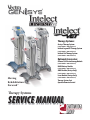
Therapy Systems
SERVICE MANUAL
ISO 13485 CERTIFIED
Vectra Genisys®/Intelect Legend XT®/ Intelect® Vet Therapy Systems
TABLE of CONTENTS
FOREWORD . . . . . . . . . . . . . . . . . . . . . . . . . . . . . . . . . . . . . . . . . . . . . . . . . . 1
1 THEORY OF OPERATION . . . . . . . . . . . . . . . . . . . . . . . . . . . . . . . . . . . . . 2
1.1 OVERVIEW . . . . . . . . . . . . . . . . . . . . . . . . . . . . . . . . . . . . . . . . . . . . . 2
1.2 POWER SUPPLY CIRCUITS . . . . . . . . . . . . . . . . . . . . . . . . . . . . . . . . 2
1.3 CONTROL BOARD . . . . . . . . . . . . . . . . . . . . . . . . . . . . . . . . . . . . . . . . 2
1.4 STIM BOARD. . . . . . . . . . . . . . . . . . . . . . . . . . . . . . . . . . . . . . . . . . . . 2
1.5 ULTRASOUND BOARD AND APPLICATOR COMBINATION
SYSTEMS ONLY . . . . . . . . . . . . . . . . . . . . . . . . . . . . . . . . . . . . . . . . . 2
1.6 USER INTERFACE AND ACCESSORIES . . . . . . . . . . . . . . . . . . . . . . . 2
2 SAFETY PRECAUTIONS . . . . . . . . . . . . . . . . . . . . . . . . . . . . . . . . . . . . . . 4
2.1 PRECAUTIONARY DEFINITIONS. . . . . . . . . . . . . . . . . . . . . . . . . . . . 4
Caution . . . . . . . . . . . . . . . . . . . . . . . . . . . . . . . . . . . . . . . . . . . . . . . . . . 4
Warning . . . . . . . . . . . . . . . . . . . . . . . . . . . . . . . . . . . . . . . . . . . . . . . . . 4
Danger . . . . . . . . . . . . . . . . . . . . . . . . . . . . . . . . . . . . . . . . . . . . . . . . . . 4
Dangerous Voltage . . . . . . . . . . . . . . . . . . . . . . . . . . . . . . . . . . . . . . . . 4
Laser . . . . . . . . . . . . . . . . . . . . . . . . . . . . . . . . . . . . . . . . . . . . . . . . . . . . 4
Corrosive . . . . . . . . . . . . . . . . . . . . . . . . . . . . . . . . . . . . . . . . . . . . . . . . . 4
Laser Eye Protection . . . . . . . . . . . . . . . . . . . . . . . . . . . . . . . . . . . . . . . 4
Spontaneous Combustion . . . . . . . . . . . . . . . . . . . . . . . . . . . . . . . . . . 4
Biohazardous Materials . . . . . . . . . . . . . . . . . . . . . . . . . . . . . . . . . . . . 4
Non-Ionizing Electromagnetic Radiation . . . . . . . . . . . . . . . . . . . . . 4
Note . . . . . . . . . . . . . . . . . . . . . . . . . . . . . . . . . . . . . . . . . . . . . . . . . . . . 4
2.2 PRECAUTIONARY INSTRUCTIONS . . . . . . . . . . . . . . . . . . . . . . . . . . 5
3 NOMENCLATURE . . . . . . . . . . . . . . . . . . . . . . . . . . . . . . . . . . . . . . . . . . . 7
3.1 VECTRA GENISYS, INTELECT LEGEND XT AND INTELECT VET
THERAPY SYSTEMS . . . . . . . . . . . . . . . . . . . . . . . . . . . . . . . . . . . . . . 7
A. Vectra Genisys, Intelect Legend XT and Intelect Vet
Therapy Systems . . . . . . . . . . . . . . . . . . . . . . . . . . . . . . . . . . . . . . . . 7
B. Vectra Genisys, Intelect Legend XT and Intelect Vets
Combination Therapy Systems . . . . . . . . . . . . . . . . . . . . . . . . . . . . 8
C. Vectra Genisys,Intelect Legend XT and Intelect Vet
Electrotherapy Systems. . . . . . . . . . . . . . . . . . . . . . . . . . . . . . . . . . 9
D. Vectra Genisys,Intelect Legend XT and Intelect Vet
Channel 3/4 Electrotherapy Module . . . . . . . . . . . . . . . . . . . . . . 10
E. Vectra GenisysIntelect Legend XT and Intelect Vet
NiMH Battery Module. . . . . . . . . . . . . . . . . . . . . . . . . . . . . . . . . . . 11
F. Vectra Genisys and Intelect Vet Laser Module . . . . . . . . . . . . . . 12
G. Vectra Genisys and Intelect Vet Laser Applicators . . . . . . . . . . . 13
H. Vectra Genisys Dual Channel sEMG Module . . . . . . . . . . . . . . . . 14
I. Vectra Genisys, Intelect Legend XT and
Intelect Vet Therapy Cart . . . . . . . . . . . . . . . . . . . . . . . . . . . . . . . . 15
J. Vectra Genisys, Intelect Legend XT and Intelect Vet
Operator Remote Control . . . . . . . . . . . . . . . . . . . . . . . . . . . . . . . . 16
3.2 VECTRA GENISYS, INTELECT LEGEND XT AND INTELECT VET
THERAPY SYSTEM HARDWARE AND SOFTWARE SYMBOL
DEFINITIONS . . . . . . . . . . . . . . . . . . . . . . . . . . . . . . . . . . . . . . . . . . . 17
A. Hardware Symbols . . . . . . . . . . . . . . . . . . . . . . . . . . . . . . . . . . . . . 17
B. Software Symbols . . . . . . . . . . . . . . . . . . . . . . . . . . . . . . . . . . . . . . 17
C. Optional Accessory Symbols . . . . . . . . . . . . . . . . . . . . . . . . . . . . . 17
4 SPECIFICATIONS . . . . . . . . . . . . . . . . . . . . . . . . . . . . . . . . . . . . . . . . . . . 18
4.1 VECTRA GENISYS, INTELECT LEGEND XT,
AND INTELECT VET THERAPY SYSTEMS . . . . . . . . . . . . . . . . . . . 18
A. Therapy Systems Physical Specifications. . . . . . . . . . . . . . . . . . 18
4.2 ELECTROTHERAPY WAVEFORM SPECIFICATIONS . . . . . . . . . . . 19
A. IFC (Interferential) Traditional (4 Pole)- Figure 4.2 . . . . . . . . . 19
B. TENS- Asymmetrical Biphasic- Figure 4.3 . . . . . . . . . . . . . . . . . 19
C. TENS- Symmetrical Biphasic- Figure 4.4 . . . . . . . . . . . . . . . . . . 20
D. High Voltage Pulsed Current (HVPC)- Figure 4.5 . . . . . . . . . . . 20
E. VMS™- Figure 4.6 . . . . . . . . . . . . . . . . . . . . . . . . . . . . . . . . . . . . . 21
F. IFC (Interferential) Premodulated (2p)- Figure 4.7 . . . . . . . . . 21
G. Russian- Figure 4.8 . . . . . . . . . . . . . . . . . . . . . . . . . . . . . . . . . . . . 22
H. Microcurrent- Figure 4.9 . . . . . . . . . . . . . . . . . . . . . . . . . . . . . . . 22
I. VMS™ Burst- Figure 4.10. . . . . . . . . . . . . . . . . . . . . . . . . . . . . . . . 23
J. DC (Direct Current)- Figure 4.11 . . . . . . . . . . . . . . . . . . . . . . . . . 23
K. Iontophoresis . . . . . . . . . . . . . . . . . . . . . . . . . . . . . . . . . . . . . . . . . 23
4.3 ULTRASOUND SPECIFICATIONS . . . . . . . . . . . . . . . . . . . . . . . . . . 24
4.4 DESCRIPTION OF DEVICE MARKINGS . . . . . . . . . . . . . . . . . . . . . 25
4.5 LASER MODULE SPECIFICATIONS . . . . . . . . . . . . . . . . . . . . . . . . 26
4.6 LASER APPLICATOR SPECIFICATIONS . . . . . . . . . . . . . . . . . . . . . 27
A. Single Diode Applicators . . . . . . . . . . . . . . . . . . . . . . . . . . . . . . . 27
B. 9, 13, and 19 Diode Applicators . . . . . . . . . . . . . . . . . . . . . . . . . 28
C. 33 Diode Applicators . . . . . . . . . . . . . . . . . . . . . . . . . . . . . . . . . . 29
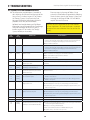
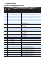
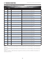
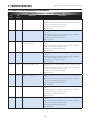
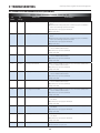
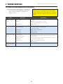
5 TROUBLESHOOTING . . . . . . . . . . . . . . . . . . . . . . . . . . . . . . . . . . . . . . . 30
5.1 THERAPY SYSTEM ERROR MESSAGES . . . . . . . . . . . . . . . . . . . . 30
5.2 THERAPY SYSTEM TESTING . . . . . . . . . . . . . . . . . . . . . . . . . . . . . 38
5.3 VISUAL INSPECTION . . . . . . . . . . . . . . . . . . . . . . . . . . . . . . . . . . . 39
5.4 LEAKAGE TESTS . . . . . . . . . . . . . . . . . . . . . . . . . . . . . . . . . . . . . . . 39
5.5 UNIT STARTUP AND FAN TESTING . . . . . . . . . . . . . . . . . . . . . . . . 39
5.6 STIMULATOR TEST SYSTEM SETUP . . . . . . . . . . . . . . . . . . . . . . . 40
5.7 VMS™ MODE TEST . . . . . . . . . . . . . . . . . . . . . . . . . . . . . . . . . . . . . 41
5.8 INTERFERENTIAL MODE TEST . . . . . . . . . . . . . . . . . . . . . . . . . . . 42
5.9 PREMODULATED MODE TEST. . . . . . . . . . . . . . . . . . . . . . . . . . . . 43
5.10 RUSSIAN MODE TEST . . . . . . . . . . . . . . . . . . . . . . . . . . . . . . . . . . 44
5.11 MICROCURRENT MODE TEST . . . . . . . . . . . . . . . . . . . . . . . . . . . . 45
5.12 HIGH VOLTAGE PULSED CURRENT HVPC MODE TEST . . . . . . 46
5.13 MICROCURRENT PROBE MODE TEST . . . . . . . . . . . . . . . . . . . . . 47
5.14 ULTRASOUND TESTS . . . . . . . . . . . . . . . . . . . . . . . . . . . . . . . . . . . 49
5.15 ULTRASOUND APPLICATOR IDENTIFICATION TEST . . . . . . . . . 49
5.16 ULTRASOUND APPLICATOR OUTPUT TEST . . . . . . . . . . . . . . . . 50
5.17 ULTRASOUND DUTY CYCLE TEST . . . . . . . . . . . . . . . . . . . . . . . . 51
5.18 COMBO OPERATION TEST . . . . . . . . . . . . . . . . . . . . . . . . . . . . . . . 52
5.19 sEMG AND sEMG + ELECTRICAL STIMULATION TESTS . . . . . . 53
5.20 NiMH BATTERY MODULE CHECKS. . . . . . . . . . . . . . . . . . . . . . . . 57
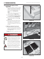
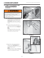
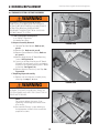
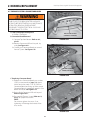
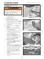
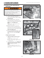
6 REMOVAL/REPLACEMENT . . . . . . . . . . . . . . . . . . . . . . . . . . . . . . . . . . 59
6.1 CHANNEL 3/4 ELECTROTHERAPY, NIMH BATTERY,
AND LASER MODULE INSTALLATION AND REMOVAL. . . . . . . . 59
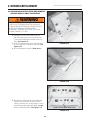
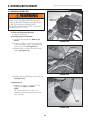
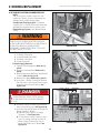
6.2 SEMG MODULE INSTALLATION AND REMOVAL
GENISYS ONLY . . . . . . . . . . . . . . . . . . . . . . . . . . . . . . . . . . . . . . . 63
i
Vectra Genisys®/Intelect Legend XT®/ Intelect® Vet Therapy Systems
TABLE of CONTENTS
6.3
6.4
6.5
6.6
6.7
6.8
THERAPY SYSTEM SEPARATING TOP & BOTTOM . . . . . . . . . . 66
THERAPY SYSTEM FAN . . . . . . . . . . . . . . . . . . . . . . . . . . . . . . . . 68
THERAPY SYSTEM CONTROL BOARD ASSEMBLY . . . . . . . . . . 69
THERAPY SYSTEM KEYMAT ASSEMBLY . . . . . . . . . . . . . . . . . . 70
THERAPY SYSTEM CONNECTOR BOARD . . . . . . . . . . . . . . . . . 71
THERAPY SYSTEM ULTRASOUND BOARD
COMBINATION SYSTEMS ONLY . . . . . . . . . . . . . . . . . . . . . . . . . 72
6.9 THERAPY SYSTEM STIM BOARD CHANNELS 1/2 . . . . . . . . 73
6.10 THERAPY SYSTEM POWER SUPPLIES . . . . . . . . . . . . . . . . . . . 74
6.11 CHANNEL 3/4 ELECTROTHERAPY MODULE
CONNECTOR BOARD . . . . . . . . . . . . . . . . . . . . . . . . . . . . . . . . . . . 76
6.12 CHANNEL 3/4 ELECTROTHERAPY MODULE STIM BOARD . . . 77
6.13 MOUNTING AND DISMOUNTING THERAPY SYSTEM AND
THERAPY SYSTEM CART . . . . . . . . . . . . . . . . . . . . . . . . . . . . . . . 78
7 GENERAL MAINTENANCE . . . . . . . . . . . . . . . . . . . . . . . . . . . . . . . . . . 79
7.1 CLEANING THE SYSTEM . . . . . . . . . . . . . . . . . . . . . . . . . . . . . . . . 79
7.2 CALIBRATION REQUIREMENTS . . . . . . . . . . . . . . . . . . . . . . . . . . 79
7.3 FIELD SERVICE . . . . . . . . . . . . . . . . . . . . . . . . . . . . . . . . . . . . . . . . 79
7.4 FACTORY SERVICE . . . . . . . . . . . . . . . . . . . . . . . . . . . . . . . . . . . . . 79
8 ULTRASOUND CALIBRATION . . . . . . . . . . . . . . . . . . . . . . . . . . . . . . . 80
8.1 GENERAL . . . . . . . . . . . . . . . . . . . . . . . . . . . . . . . . . . . . . . . . . . . . . 80
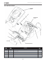
9 PARTS. . . . . . . . . . . . . . . . . . . . . . . . . . . . . . . . . . . . . . . . . . . . . . . . . . . 81
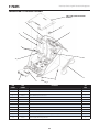
9.1 TOP TO BOTTOM ASSEMBLY . . . . . . . . . . . . . . . . . . . . . . . . . . . . . 81
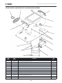
9.2 COMBINATION SYSTEM BASE ASSEMBLY . . . . . . . . . . . . . . . . . 82
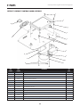
9.3 COMBINATION STIM & ULTRASOUND PC BOARD ASSEMBLY . 83
9.4 TOP HOUSING ASSEMBLY . . . . . . . . . . . . . . . . . . . . . . . . . . . . . . . 84
9.5 VECTRA GENISYS AND INTELECT VET
CONTROL BOARD ASSEMBLY . . . . . . . . . . . . . . . . . . . . . . . . . . . . 85
9.6 INTELECT LEGEND XT CONTROL BOARD ASSEMBLY . . . . . . . . 86
9.7 CHANNEL 3/4 ELECTROTHERAPY MODULE ASSEMBLY . . . . . . 87
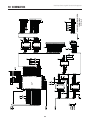
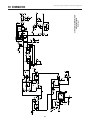
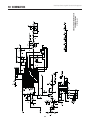
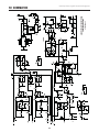
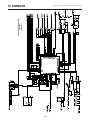
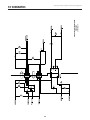
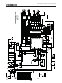
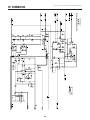
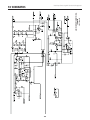
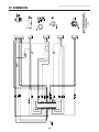
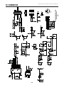
10 SCHEMATICS. . . . . . . . . . . . . . . . . . . . . . . . . . . . . . . . . . . . . . . . . . . . . 88
10.1 VECTRA GENISYS, INTELECT LEGEND XT,
AND INTELECT VET THERAPY SYSTEM- CONTROL BOARD . . 88-90
10.2 VECTRA GENISYS, INTELECT LEGEND XT AND INTELECT VET
THERAPY SYSTEM-ULTRASOUND PC BOARD . . . . . . . . . . . . . 91-93
10.3 VECTRA GENISYS, INTELECT LEGEND XT AND
INTELECT VET THERAPY SYSTEM- STIM BOARD . . . . . . . . . 94-103
10.4 VECTRA GENISYS, INTELECT LEGEND XT AND
INTELECT VET THERAPY SYSTEM- CONNECTOR BOARD . . . . . . 104
10.5 VECTRA GENISYS, INTELECT LEGEND XT AND INTELECT VET
THERAPY SYSTEM- CHANNEL 3/4 ELECTROTHERAPY MODULE
CONNECTOR BOARD . . . . . . . . . . . . . . . . . . . . . . . . . . . . . . . . . . . 105
10.6 VECTRA GENISYS, INTELECT LEGEND XT AND INTELECT VET
THERAPY SYSTEM- POWER SUPPLIES . . . . . . . . . . . . . . . . . . . . 106
10.7 VECTRA GENISYS AND INTELECT VET THERAPY
SYSTEM- LASER MODULE BOARD . . . . . . . . . . . . . . . . . . . . . . . . 107
11 WARRANTY. . . . . . . . . . . . . . . . . . . . . . . . . . . . . . . . . . . . . . . . . 108109
ii
Vectra Genisys®/Intelect Legend XT®/ Intelect® Vet Therapy Systems
FOREWORD
Read, understand, and follow the Safety Precautions and all other information contained in this
manual.
This manual contains the necessary safety and field service information for those field service
technicians, certified by Chattanooga Group, to perform field service on the Vectra Genisys, Intelect
Legend XT and Intelect Vet Therapy Systems, modules, and accessories.
At the time of publication, the information contained herein was current and up-to-date. However,
due to continual technological improvements and increased clinical knowledge in the field of
electrotherapy, ultrasound, Iontophoresis, and Laser therapy, as well as Chattanooga Group’s policy
of continual improvement, Chattanooga Group reserves the right to make periodic changes and
improvements to their equipment and documentation without any obligation on the part of
Chattanooga Group.
It is the sole responsibility for certified field service technicians to stay informed and trained in the
latest technology utilized in the Vectra Genisys, Intelect Legend XT and Intelect Vet Therapy Systems
by Chattanooga Group. From time to time, as significant improvements are incorporated, service
bulletins will be produced and made available on our web site (chattgroup.com) in lieu of reprinting
a complete manual prematurely. These service bulletins will provide updated service information
and technological improvements to the Vectra Genisys, Intelect Legend XT and Intelect Vet Therapy
Systems for use by certified service technicians.
Due to the complex nature of the technology utilized by Chattanooga Group, the recommended
troubleshooting techniques are to determine “Bad Board” and board replacement only. No board
component level troubleshooting is recommended, nor will information or parts be supplied by
Chattanooga Group.
Any board component level troubleshooting performed will be at the sole risk and liability of the
certified field service technician performing such troubleshooting techniques. Performance of such
techniques may render the warranty null and void.
The Vectra Genisys and Intelect Legend XT equipment is to be used only under the
prescription and supervision of a licensed medical practitioner.
The Intelect Vet is to be used only under the prescription and supervision of a licensed
veterinarian.
©2008 Encore Medical, L.P. and its affiliates, Austin, Texas, USA. Any use of editorial, pictorial, or layout composition of this publication without express written consent from
Chattanooga Group of Encore Medical, L.P. is strictly prohibited. This publication was written, illustrated, and prepared for distribution by Chattanooga Group of Encore Medical, L.P.
1
Vectra Genisys®/Intelect Legend XT®/ Intelect® Vet Therapy Systems
1 THEORY OF OPERATION
1.1 OVERVIEW
The Vectra Genisys, Intelect Legend XT and Intelect Vet Therapy Systems are comprised of several PC board
assemblies housed within a common enclosure. These assemblies each support a distinct function in
the product. The basic elements are User Interface, Control Board, Stim Board, Ultrasound Board, Ultrasound
Applicator, and Power Supply Circuits.
When a Module (Channel 3/4 Electrotherapy, NiMH Battery, Laser, or sEMG) is installed, the Control Board
software automatically recognizes that a Module has been installed and prompts the installer to perform
certain tasks, for verification of Module installed, to make the respective Module fully functional. No additional
software installation is required as the Therapy System contains all necessary software to accommodate any
Module installation.
1.2 POWER SUPPLY CIRCUITS
A universal input 100 Watt power supply provides the Control Board and Stim Board of the system with 24
volts DC. The supply is connected to the mains at all times when the cord is attached. The 24 VDC supply is
regulated locally at each PC board as required. On Combination Systems, a separate universal 75 Watt Power
Supply provides 24 volts DC to the Ultrasound PC Board. The 24 volt DC power is regulated at the board, as
required.
1.3 CONTROL BOARD
The Control Board serves just as its name implies. It controls the operation of the stim board, ultrasound
board, user interface, optional modules, and accessories. The control board communicates to the stim
boards and ultrasound board through a proprietary bus. The control board drives the display. The control
board reads the menu buttons. The control board also reads the amplitude and the contrast control (Intelect
XT Only) systems. The control board reads and manages the Multimedia (MMC) Card, Patient Data Card,
and sEMG Data Card. Sound output is generated by the control board and routed to an internal speaker.
The control board reads the optional Patient Interrupt Switch and Operator Remote Control (used to
administer Manual Stimulation Therapy).
1.4 STIM BOARD
The Stim Board creates all muscle stimulation output. Communications to the Stim Board is via a
proprietary bus. A Processor on the Stim Board acts on messages passed to it by the Control Board to
set up waveforms and adjust output amplitude. Information can likewise be passed from the Stim
Board back to the Control Board for monitoring Current, Microcurrent Probe (Vectra Genisys and
Intelect Legend XT only) Contact Quality indication, etc. If the Stim Board does not respond as
expected to a command from the Control Board, output is stopped and an Error Message is generated.
1.5 ULTRASOUND BOARD AND APPLICATOR COMBINATION SYSTEMS ONLY
The Ultrasound Board generates the 1 or 3.3 MHz output to drive the Sound Head of the Applicator. The
Ultrasound Board is accessed through the proprietary bus by the Control Board. It can provide current and
voltage information about the ultrasound output of the board. The calibration data for the Sound Head is
passed through the Ultrasound Board from the Applicator to the Control Board. By storing the calibration
data in the Applicator, there is no calibration necessary for the Ultrasound Board and any calibrated
Chattanooga Group Vectra Genisys, Intelect Legend XT, or Intelect Vet Ultrasound Applicator can be
connected and operated to provide accurate coupling and output.
1.6 USER INTERFACE AND ACCESSORIES
The LCD display panel provides the operator visible feedback in the way of menu choices. Pressing of the
menu buttons makes selections from the menus. The control board interprets these user inputs and responds
accordingly. Audible feedback is given as well for events such as key presses and end of treatment.
The control board accesses the Patient Data Card, sEMG Data Card and MMC Card via an on board Reader/
Writer Interface. The voltage necessary to operate the reader is provided by the 100 Watt Power Supply and is
regulated by the Control Board.
A. Channel 3/4 Electrotherapy Module
The Channel 3/4 Electrotherapy Module creates all muscle stimulation output for Channels 3 and 4.
The Channel 3/4 Electrotherapy Module is interfaced with the System via a ribbon cable which
supplies power and facilitates communication between the stim board and control board of the
system. All waveforms available to channels 1 and 2 are available to channels 3 and 4 via the system
software. No additional software is required for full functionality of the module.
2
Vectra Genisys®/Intelect Legend XT®/ Intelect® Vet Therapy Systems
1 THEORY OF OPERATION
1.6 USER INTERFACE AND ACCESSORIES (CONTINUED)
B. NiMH Battery Module
The NiMH Battery Module incorporates two Nickel Metal Hydride (NiMH) Battery packs and
a PC Board. The PC Board monitors the Charge Level of the Batteries. The Batteries supply 24 VDC to
the system which is then distributed to the respective pcb’s through the system power supply.
The Battery Module is interfaced with the system via a ribbon cable that facilitates communication
with the Control Board and delivery of power to a Two Channel Electrotherapy or Combination
Therapy System. When the Therapy System is connected to a Mains Power Supply via the Power
Cord, the NiMH Battery Module will charge. Once the Module is fully charged the software will stop
the charging process eliminating the possibility of overcharging. Battery power is used only when
the Therapy System is not connected to a Mains Power Supply.
C. Laser Module and Applicators (Genisys and Intelect Vet Therapy Systems ONLY)
The Laser Module utilizes a PC Board to communicate with the Control Board via a ribbon cable. The
Laser Module supplies the power required for each Laser Applicator through the Laser Applicator
Cable to PC Boards mounted within the Applicator housing. All Calibration Data for the Applicators
is stored on board the respective Applicator. Each Applicator incorporates a lens that is instrumental
in delivery of the laser radiation to the patient. The Laser applicators are classified as Class 3B
Laser products and are capable of up to 1440 nm of laser radiation in the infrared spectrum.
Approved eye protection must be worn by all persons in the vicinity when the Laser is on. The
Therapy System incorporates and demands entry of a unique PIN before operation of the Laser
Applicators is allowed by the Therapy System. The Module also incorporates a Therapy Room Door
Lockout Jack to accommodate a lockout switch that would prevent operation of the Laser
Applicators should the lockout safety device be breached by persons entering or exiting the therapy
room. Purchase and installation of the Lockout Device is the responsibility of the facility or clinic.
D. sEMG Module (Genisys Therapy Systems ONLY)
The Surface Electromyography (sEMG) Module utilizes a PC board to communicate to the Stim and
Control Boards via direct PC Board Contacts. The sEMG module reads and transmits muscle activity
through lead wires and electrodes. The sEMG Module communicates muscle activity data to the Control
Board which can store the data on an sEMG Data Card via the on board Card Reader/Writer for viewing on
a PC in graph form via the optional Chattanooga Group Patient Data Management System (PDMS)
Software and Card Reader.
E. Operator Remote Control
The Operator Remote Control is just as its name indicates and incorporates a PC Board. The Channel 1/2
Operator Remote Control is interfaced with the Therapy System through its unique connector on the
front of the Therapy System and the Channel 3/4 Electrotherapy Module. The Operator Remote Control
communicates with the Stim Board(s) to the Control Board for the administration of Manual Stim Therapy
only.
F. Therapy System Cart
The Therapy System Cart is designed for use with the Chattanooga Group Therapy Systems only. The
cart alone provides mobility to the Therapy System and storage of necessary accessories and supplies
used in conjunction with the Therapy System.
3
Vectra Genisys®/Intelect Legend XT®/ Intelect® Vet Therapy Systems
2 SAFETY PRECAUTIONS
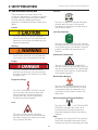
Corrosive
2.1 PRECAUTIONARY DEFINITIONS
The precautionary instructions found in this
section and throughout this manual are indicated
by specific symbols. Understand these symbols
and their definitions before operating this
equipment. The definition of these symbols are as
follows:
Text with a “CORROSIVE" indicator will explain
possible safety infractions if the chemical
components of the battery are exposed to air,
skin, or other materials.
Caution
Laser Eye Protection
Text with a “CAUTION” indicator will explain
possible safety infractions that could have the
potential to cause minor to moderate injury or
damage to equipment.
Text with a “LASER EYE PROTECTION" indicator
will explain possible safety infractions that could
cause serious eye injury or blindness if the eyes
are directly or reflectively exposed to Laser
Radiation.
Warning
Text with a “WARNING” indicator will explain
possible safety infractions that will potentially
cause serious injury and equipment damage.
Spontaneous Combustion
Danger
Text with a “SPONTANEOUS COMBUSTION"
indicator will explain possible safety infractions
that could create conditions for a Spontaneous
Combustion if the material is mishandled and
not disposed of properly.
Text with a “DANGER” indicator will explain
possible safety infractions that are imminently
hazardous situations that would result in death
or serious injury.
Biohazardous Materials
Dangerous Voltage
Text with a “BIOHAZARD” indicator serves to
inform the user of possible hazards resulting
in improper handling of components and
accessories that have come in contact with
bodily fluids.
Text with a “DANGEROUS VOLTAGE” indicator
serves to inform the technician of possible
hazards resulting in the electrical charge
disbursement from certain components if
handled or serviced improperly.
Non-Ionizing Electromagnetic Radiation
Laser
Text with a “NON-IONIZING ELECTROMAGNETIC
RADIATION" indicator informs the user of
possible hazards resulting from elevated,
potentially dangerous, levels of non-ionizing
radiation.
Note
Throughout this manual “NOTE” may be found.
These Notes are helpful information to aid in
the particular area or function being described.
Text with a “LASER" indicator will explain
possible safety infractions that are imminently
hazardous situations that would result serious
injury to eyes or blindness.
4
Vectra Genisys®/Intelect Legend XT®/ Intelect® Vet Therapy Systems
2 SAFETY PRECAUTIONS
2.2 PRECAUTIONARY INSTRUCTIONS
• The Vectra Genisys Therapy System, the Intelect Legend XT
• Read, understand, and practice the precautionary and
operating instructions. Know the limitations and hazards
associated with using any laser device. Observe the
precautionary and operational decals placed on the unit.
• Do not operate this unit when connected to any unit other
than Chattanooga Group devices.
• Do not operate this unit in an environment where
other devices are being used that intentionally radiate
electromagnetic energy in an unshielded manner. Portable
and mobile RF communications equipment can affect
Medical Electrical Equipment.
• The Laser System should be routinely checked before
each use to determine that all controls function normally;
especially that the dosage control properly adjusts the
intensity of the laser output in a stable manner. Also,
determine that the treatment time control actually terminates
the laser output when the timer reaches zero.
• Ultrasound should be routinely checked before each use to
determine that all controls function normally, especially that
the intensity control does properly adjust the intensity of the
ultrasonic power output in a stable manner. Also, determine
that the treatment time control does actually terminate
ultrasonic power output when the timer reaches zero.
• DO NOT use sharp objects such as a pencil point or ballpoint
pen to operate the buttons on the control panel as damage
may result.
• Use of controls or adjustments or performance of procedures
other than those specified herein may result in hazardous
exposure to laser energy.
• Handle all Applicators with care. Inappropriate handling of
the Laser Applicator may adversely affect its characteristics.
• Inspect Laser Applicator, Lenses, Cables, and associated
connectors before each use. Do not use a damaged or
otherwise compromised Laser Applicator.
• This unit should be operated, transported and stored in
temperatures between 59° F and 104° F (15° C and 40° C),
with Relative Humidity ranging from 30%-60%.
• Where the integrity of the external protective earth conductor
arrangement is in doubt, equipment shall be operated from
its internal electrical power source.
• DO NOT permit any foreign materials or liquids to enter the
unit. Take care to prevent any foreign materials including, but
not limited to, inflammables, water, and metallic objects from
entering the unit. These may cause unit damage, malfunction,
electrical shock, fire, or personal injury.
• Before each use, inspect Ultrasound Applicator for cracks,
which may allow the ingress of conductive fluid.
• Inspect all cables and associated connectors before
each use.
• This equipment generates, uses and can radiate radio
frequency energy and, if not installed and used in
accordance with the instructions, may cause harmful
interference to other devices in the vicinity. However,
there is no guarantee that interference will not occur in
a particular installation. Harmful interference to other
devices can be determined by turning this equipment on
and off. Try to correct the interference using one or more
of the following: reorient or relocate the receiving device,
increase the separation between the equipment, connect
the equipment to an outlet on a different circuit from that
to which the other device(s) are connected and consult the
factory field service technician for help.
•
•
Therapy System and the Intelect Vet Therapy System are not
designed to prevent the ingress of water or liquids. Ingress
of water or liquids could cause malfunction of internal
components of the system and therefore create a risk of
injury to the patient.
Nylatex® Wraps contain dry natural rubber and may cause
allergic reactions in patients with allergies to latex.
Use of parts or materials other than Chattanooga Group's
can degrade minimum safety.
• U.S.A. Federal Law restricts these devices to sale by, or on
the order of, a physician or licensed practitioner. This device
should be used only under the continued supervision of a
physician or licensed practitioner.
• Make certain the unit is electrically grounded by connecting
only to a grounded electrical service receptacle conforming
to the applicable national and local electrical codes.
• This device should be kept away from children.
• Care must be taken when operating this equipment around
other equipment. Potential electromagnetic or other
interference could occur to this or to the other equipment.
Try to minimize this interference by not using other
equipment in conjunction with it.
• This equipment is not designed to prevent the ingress of water
or liquids. Ingress of water or liquids could cause malfunction
of internal components of the system and therefore create a
risk of injury to the patient.
• Do not drop the applicator or unit on hard surfaces. Do not
cool an overheated applicator with ice water or ice packs. Do
not allow the applicator to reach maximum temperatures
repeatedly. Do not submerge the applicator or unit in water.
All of these conditions will damage the applicator and unit.
Damage resulting from these conditions is not covered under
the warranty.
• The safety of TENS waveforms for use during pregnancy or
birth has not been established.
• TENS is not effective for pain of central origin. (This includes
headache.)
• TENS should be used only under the continued supervision
of a physician or licensed practitioner.
• TENS waveforms have no curative value.
• TENS is a symptomatic treatment, and as such, suppresses
the sensation of pain which would otherwise serve as a
protective mechanism.
• Electronic monitoring equipment (such as ECG monitors
and ECG alarms) may not operate properly when TENS
stimulation is in use.
• In the event that an Error message or Warning appears
beginning with a 2 or 3, immediately stop all use of the
system and contact the dealer or Chattanooga Group for
service. Errors and Warnings in these categories indicate an
internal problem with the system that must be tested by
Chattanooga Group or a Field Service Technician certified
by Chattanooga Group before any further operation or
use of the system. Use of a system that indicates an Error
or Warning in these categories may pose a risk of injury to
the patient, user or cause extensive internal damage to the
system.
5
Vectra Genisys®/Intelect Legend XT®/ Intelect® Vet Therapy Systems
2 SAFETY PRECAUTIONS
2.2 PRECAUTIONARY INSTRUCTIONS (CONTINUED)
• Use of controls or adjustments or performance of
•
•
•
•
•
•
•
•
•
•
•
• DO NOT connect the unit to an electrical supply without
first verifying that the power supply is the correct
voltage. Incorrect voltage may cause unit damage,
malfunction, electrical shock, fire, or personal injury. Your
unit was constructed to operate only on the electrical
voltage specified on the Voltage Rating and Serial
Number Plate. Contact your dealer if the unit is not
properly rated.
• When the unit is on, not all wavelengths are visible
to the naked eye. Therefore, when performing any
operational or functional check, make certain all persons
in the vicinity of the laser wear Chattanooga Group laser
protective eyewear.
• DO NOT point the laser beam directly into human or
animal eyes. The lens of the eye does not detect the
invisible, coherent laser beams, potentially resulting in
permanent retinal damage.
• Class 3B Lasers are considered an acute hazard to the
skin and eyes from direct radiation. Eye injury will occur
is laser is viewed directly or from specular frelection. Eye
protection is required for all persons in the treatment
area.
procedures other than those specified herein may result in
hazardous exposure to ultrasonic energy.
Before administering any treatment to a patient you should
become acquainted with the operating procedures for
each mode of treatment available, as well as the indications,
contraindications, warnings and precautions. Consult
other resources for additional information regarding the
application of Electrotherapy and Ultrasound.
To prevent electrical shock, disconnect the unit from
the power source before attempting any maintenance
procedures.
Keep electrodes separated during treatment. Electrodes in
contact with each other could result in improper stimulation
or skin burns.
Long term effects of chronic electrical stimulation are
unknown.
Stimulation should not be applied over the anterior neck
or mouth. Severe spasm of the laryngeal and pharyngeal
muscles may occur and the contractions may be strong
enough to close the airway or cause difficulty in breathing.
Stimulation should not be applied transthoracically in that
the introduction of electrical current into the heart may
cause cardiac arrhythmia.
Stimulation should not be applied over swollen, infected,
and inflamed areas or skin eruptions, e.g., phlebitis,
thrombophlebitis, varicose veins, etc.
Stimulation should not be applied over, or in proximity to,
cancerous lesions.
Output current density is related to electrode size. Improper
application may result in patient injury. If any question
arises as to the proper electrode size, consult a licensed
practitioner prior to therapy session.
The Vectra Genisys Therapy System optional modules and
associated accessories are designed for use only with the
Chattanooga Group Vectra Genisys Electrotherapy and
Combination Therapy Systems.
Remove the Ultrasound or Laser Applicator by pulling the
cable connector only. DO NOT remove by pulling the cable.
• Power Supplies retain High Voltage!
• NiMH batteries contain Class E corrosive materials. In the
event of battery cell rupture or leakage, handle battery
module wearing neoprene or natural rubber gloves.
Contents of a ruptured or leaking battery can cause
respiratory irritation. Hypersensitivity to nickel can cause
allergic pulmonary asthma. Contents of cell coming in
contact with skin can cause skin irritation and chemical
burns.
• Never, under any circumstances, open the battery
cells. Should an individual cell from a battery become
disassembled, spontaneous combustion of the negative
electrode is possible. There can be a delay between
exposure to air and spontaneous combustion.
• Charge the Battery Module according to the
instructions found in this manual. Never attempt to
charge the Battery Module on any other charging
mechanism.
• Use the Battery Module only with the Vectra Genisys
Therapy Systems.
• Do not reverse the polarity of the Battery Module. Doing
so can increase the individual cell temperature and
cause cell rupture or leakage.
• Never dispose of Battery Module in fire. Never short
circuit the battery. The battery may explode, ignite, leak
or get hot causing serious personal injury.
• Dispose of NiMH batteries according to national, state
and local codes and regulations.
• Stimulus delivered by the TENS waveforms of this
device, in certain configurations, will deliver a charge of
25 microcoulombs (μC) or greater per pulse and may
be sufficient to cause electrocution. Electrical current
of this magnitude must not flow through the thorax
because it may cause a cardiac arrhythmia.
• Patients with an implanted neurostimulation device
must not be treated with or be in close proximity to
any shortwave diathermy, microwave diathermy,
therapeutic ultrasound diathermy or laser diathermy
anywhere on their body. Energy from diathermy
(shortwave, microwave, ultrasound and laser) can be
transferred through the implanted neurostimulation
system, can cause tissue damage, and can result in
severe injury or death. Injury, damage or death can
occur during diathermy therapy even if the implanted
neurostimulation system is turned “off.”
• Handle, clean and dispose of components and
accessories that have come in contact with bodily
fluids according to National, Local and Facility rules,
regulations and procedures.
6
Vectra Genisys®/Intelect Legend XT®/ Intelect® Vet Therapy Systems
3 NOMENCLATURE
3.1 VECTRA GENISYS, INTELECT LEGEND XT AND INTELECT VET THERAPY SYSTEMS
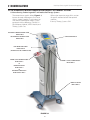
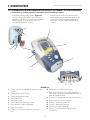
A. Vectra Genisys, Intelect Legend XT and Intelect Vet Therapy Systems
Refer to the respective pages of this section
for specific nomenclature of the optional
modules.
* Genisys Therapy Systems ONLY
The nomenclature graphic below, Figure 3.1,
locates the major components of an Vectra
Genisys, Intelect Legend XT and Intelect Vet
two channel combination therapy system
equipped with the following: Channel 3/4
Electrotherapy Module, *sEMG Module, and
Therapy System Cart.
TWO CHANNEL COMBINATION THERAPY SYSTEM
REFER TO PAGE 8
TWO CHANNEL ELECTROTHERAPY SYSTEM
REFER TO PAGE 9
ULTRASOUND APPLICATOR
DUAL CHANNEL SEMG MODULE*
REFER TO PAGE 14
INSTALLED TO BOTTOM OF THERAPY SYSTEM
CHANNEL 3/4 ELECTROTHERAPY MODULE
REFER TO PAGE 10
OR
NIMH BATTERY MODULE
REFER TO PAGE 11
OR
LASER MODULE & APPLICATORS*
REFER TO PAGES 12 AND 13
CHANNELS 1/2 AND 3/4 OPERATOR REMOTE
REFER TO PAGE 16
THERAPY SYSTEM CART
REFER TO PAGE 15
FIGURE 3.1
7
Vectra Genisys®/Intelect Legend XT®/ Intelect® Vet Therapy Systems
3 NOMENCLATURE
3.1 VECTRA GENISYS, INTELECT LEGEND XT AND INTELECT VET THERAPY SYSTEMS (CONTINUED)
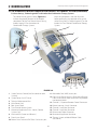
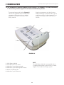
B. Vectra Genisys, Intelect Legend XT and Intelect Vet Combination Therapy Systems
The nomenclature graphics below, Figure 3.2,
indicate the general locations of the exterior
components of the Two Channel Vectra Genisys,
Intelect Legend XT or the Intelect Vet
Combination Therapy Systems.
Know the components and their functions
before performing any operation of or service
to the Vectra Genisys, Intelect Legend XT or the
Intelect Vet Two Channel Combination Therapy
Systems.
6
11
1
8
7
2
3
4
5
10
9
19
12
17
15
13
14
16
18
FIGURE 3.2
1. Screen Contrast Control (Not functional on color
Systems)
2. System Power On/Off Switch
3. Technical Maintenance Port
4. Main Power Cord
5. Rear Access Panel
6. Two Channel Combo System
7. Ultrasound Applicator (5cm2 shown) Combo
Systems Only
8. User Interface (Screen and Buttons)
9. Front Access Panel
10. Patient Data Card and sEMG Data Card access port
11. Multimedia Card (MMC) access port
12. Front Access Panel Lanyard- When reinstalling the
Front Access Panel, make certain the Lanyard does
not become kinked
13. Channel 1/2 Operator Remote Control Connector
14. Patient Interrupt Switch Connector
15. Channel 1 Lead Wire Connector
16. Channel 2 Lead Wire Connector
17. Microcurrent Probe Connector
18. Ultrasound Applicator Connector
19. Therapy System to Module Ribbon Cable
(not shown)
8
Vectra Genisys®/Intelect Legend XT®/ Intelect® Vet Therapy Systems
3 NOMENCLATURE
3.1 VECTRA GENISYS, INTELECT LEGEND XT AND INTELECT VET THERAPY SYSTEMS (CONTINUED)
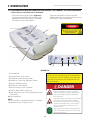
C. Vectra Genisys, Intelect Legend XT and Intelect Vet Electrotherapy Systems
The nomenclature graphics below, Figure 3.3,
indicate the general locations of the exterior
components of the Two Channel Vectra Genisys,
Intelect Legend XT or the Intelect Vet Two
Channel Electrotherapy Systems.
Know the components and their functions
before performing any operation of or service
to the Vectra Genisys, Intelect Legend XT or
the Intelect Vet Two Channel Electrotherapy
Systems.
1
6
3
2
7
10
4
5
8
9
17
11
16
14
12
13
15
FIGURE 3.3
1. Screen Contrast Control (Not functional on Color
Systems)
2. System Power On/Off Switch
3. Technical Maintenance Port
4. Main Power Cord
5. Rear Access Panel
6. Two Channel Electrotherapy System
7. User Interface (Screen and Buttons)
8. Front Access Panel
9. Patient Data Card and sEMG Data Card access
port
10. Multimedia Card (MMC) access port
11. Front Access Panel Lanyard- When reinstalling
the Front Access Panel, make certain the Lanyard
does not become kinked
12. Channel 1/2 Operator Remote Control Connector
13. Patient Interrupt Switch Connector
14. Channel 1 Lead Wire Connector
15. Channel 2 Lead Wire Connector
16. Microcurrent Probe Connector
17. Therapy System to Module Ribbon Cable
(not shown)
9
Vectra Genisys®/Intelect Legend XT®/ Intelect® Vet Therapy Systems
3 NOMENCLATURE
3.1 VECTRA GENISYS, INTELECT LEGEND XT AND INTELECT VET THERAPY SYSTEMS (CONTINUED)
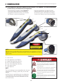
D. Vectra Genisys, Intelect Legend XT and Intelect Vet Channel 3/4 Electrotherapy Module
The nomenclature graphics below, Figure 3.4,
indicate the general locations of the exterior
components of the Vectra Genisys, Intelect
Legend XT and Intelect Vet Therapy Systems
Channel 3/4 Electrotherapy Module.
Know the components and their functions
before performing any operation of or service
to the Vectra Genisys, Intelect Legend XT and
Intelect Vet Therapy Systems Channel 3/4
Electrotherapy Module.
6
5
1
2
4
3
7
9
8
11
10
FIGURE 3.4
1.
2.
3.
4.
5.
6.
7.
8.
9.
10.
11.
Also Included:
• Four 4mm X 20mm mounting screws
• Channel 3 and 4 Lead Wires
• Sample of Dura-Stick™ II electrodes
NOTE:
The Channel 3/4 Electrotherapy Module is not
operable unless it is properly connected to a Vectra
Genisys, Intelect Legend XT or an Intelect Vet Therapy
System.
Two (2) Channel Electrotherapy Module
Extended Front Access Panel
Module to System Mounting Holes
Module to System Feet Alignment Indents
Power Cord Routing Port
Module to System Connector
Operator Remote Control Connector
Patient Interrupt Switch Connector
Channel 3 Lead Wire Connector
Channel 4 Lead Wire Connector
Microcurrent Probe Connector
10
Vectra Genisys®/Intelect Legend XT®/ Intelect® Vet Therapy Systems
3 NOMENCLATURE
3.1 VECTRA GENISYS, INTELECT LEGEND XT AND INTELECT VET THERAPY SYSTEMS (CONTINUED)
E. Vectra Genisys, Intelect Legend XT and Intelect Vet NiMH Battery Module
The nomenclature graphic below, Figure 3.5,
indicates the general locations of the exterior
components of the Vectra Genisys, Intelect
Legend XT and Intelect Vet Systems NiMH
Battery Module.
Know the components and their functions
before performing any operation of or service
to the Vectra Genisys, Intelect Legend XT and
Intelect Vet Therapy Systems NiMH Battery
Module.
6
5
1
2
4
3
FIGURE 3.5
1.
2.
3.
4.
5.
6.
NOTE:
The NiMH Battery Module is not operable unless it
is properly connected to an Vectra Genisys, Intelect
Legend XT, or Intelect Vet Therapy System.
NiMH Battery Module
Extended Front Access Panel
Module to System Mounting Holes
Module to System Feet Alignment Indents
Power Cord Routing Port
Module to System Connector
11
Vectra Genisys®/Intelect Legend XT®/ Intelect® Vet Therapy Systems
3 NOMENCLATURE
3.1 VECTRA GENISYS, INTELECT LEGEND XT AND INTELECT VET THERAPY SYSTEMS (CONTINUED)
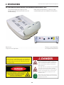
F. Vectra Genisys and Intelect Vet Laser Module
The nomenclature graphic below, Figure 3.6,
Know the components and their functions
indicates the general locations of the exterior
before performing any operation of or service to
components of the Vectra Genisys and Intelect
the Therapy System Laser Module.
Vet Therapy System Laser Module.
6
5
1
2
4
3
7
8
9
10
FIGURE 3.6
1. Laser Module
2. Extended Front Access Panel
3. Module to System Mounting Holes
4. Module to System Feet Alignment Indents
5. Power Cord Routing Port
6. Module to System Header
7. Patient Interrupt Switch (Optional)
8. Therapy Room Door Lockout Jack
9. Point Locator (for use with Single Applicator Laser
Applicators)
10. Laser Applicator
NOTE:
The Laser Module is not operable unless it is properly
connected only to its Therapy System.
NOTE:
No Field Service is applicable to the Laser Module or
Laser Applicators. All Laser Modules and Applicators
suspected to require service or calibration must be
sent to the factory.
• DO NOT point the laser beam directly into
human or animal eyes. The lens of the eye
does not detect the invisible, coherent laser
beams, potentially resulting in permanent
retinal damage.
• Class 3B Lasers are considered an acute hazard
to the skin and eyes from direct radiation.
Eye injury will occur if laser is viewed directly
or from specular reflection. Laser protective
eyewear is required for all persons in the
treatment area.
• Approved Laser protective eyewear must be
worn at all times by all persons in the vicinity
when the Laser is On.
12
Vectra Genisys®/Intelect Legend XT®/ Intelect® Vet Therapy Systems
3 NOMENCLATURE
3.1 VECTRA GENISYS, INTELECT LEGEND XT AND INTELECT VET THERAPY SYSTEMS (CONTINUED)
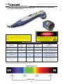
G. Vectra Genisys and Intelect Vet Laser Applicators
The nomenclature graphics below, Figure 3.7,
Know the components and their functions
indicate the general locations of the exterior
before performing any operation of or service
components of the Vectra Genisys and Intelect
to the Vectra Genisys and Intelect Vet Therapy
Vet Therapy System Laser Applicators.
System Laser Therapy System Laser Applicators.
1
2
7
7
3
1
6
6
2
4
1
2
5
6
NOTE:
No Field Service is applicable to the Laser Module or Laser Applicators. All Laser
Modules and Applicators suspected to require service or calibration must be sent
to the factory.
7
FIGURE 3.7
1. Laser On LED
2. Laser Applicator On/Off Button
3. Single Diode Applicator Housing
4. LED Cluster Applicator Housing
5. Laser Cluster Applicator Housing
6. Laser Aperture Lens
7. Laser Aperture
NOTE:
The Laser Applicators are not operable unless they are
connected to its Therapy Systems only via the Laser
Module.
No Field Service is applicable to the Laser Module or
Laser Applicators. All Laser Modules and Applicators
suspected to require service or calibration must be
sent to the factory.
• DO NOT point the laser beam directly into
human or animal eyes. The lens of the eye
does not detect the invisible, coherent laser
beams, potentially resulting in permanent
retinal damage.
• Class 3B Lasers are considered an acute hazard
to the skin and eyes from direct radiation.
Eye injury will occur if laser is viewed directly
or from specular reflection. Laser protective
eyewear is required for all persons in the
treatment area.
• Approved Laser protective eyewear must be
worn at all times by all persons in the vicinity
when the Laser is On.
13
Vectra Genisys®/Intelect Legend XT®/ Intelect® Vet Therapy Systems
3 NOMENCLATURE
3.1 VECTRA GENISYS, INTELECT LEGEND XT AND INTELECT VET THERAPY SYSTEMS (CONTINUED)
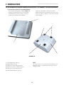
H. Vectra Genisys Dual Channel sEMG Module
The nomenclature graphics below, Figure 3.8,
indicate the general locations of the exterior
components of the Vectra Genisys Therapy
System Dual Channel sEMG Module.
Know the components and their functions
before performing any operation of or service to
the Vectra Genisys Therapy System Dual Channel
sEMG Module.
1
4
3
2
6
5
FIGURE 3.8
1.
2.
3.
4.
5.
6.
sEMG Module Top Housing
Module Removal Slot
Module to System Mounting Tabs
Module to System PC Board Contacts
Module to System Retaining Tab
sEMG Module Bottom Housing
NOTE:
The Vectra Genisys Dual Channel sEMG Module is not
operable unless it is connected to the Vectra Genisys
Therapy System.
14
Vectra Genisys®/Intelect Legend XT®/ Intelect® Vet Therapy Systems
3 NOMENCLATURE
3.1 VECTRA GENISYS, INTELECT LEGEND XT AND INTELECT VET THERAPY SYSTEMS (CONTINUED)
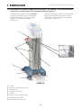
I. Vectra Genisys, Intelect Legend XT and Intelect Vet Therapy System Cart
The nomenclature graphics below, Figure 3.9,
indicate the general locations of the exterior
components of the Vectra Genisys, Intelect
Legend XT and Intelect Vet Therapy
Systems Cart.
Know the components and their functions before
performing any operation of or service to the
Vectra Genisys, Intelect Legend XT and Intelect
Vet Therapy Systems Cart.
1
3
2
4
8
5
6
7
FIGURE 3.9
1.
2.
3.
4.
5.
6.
7.
8.
Cart Top
System to Cart Retaining Screw (4)
Storage Bins (6)
Cart Rear Swivel Casters
Cart Base
Cart Front Swivel, Locking Casters
Cart Bottom Access Plate
Front and Rear Cart Extrusions
15
Vectra Genisys®/Intelect Legend XT®/ Intelect® Vet Therapy Systems
3 NOMENCLATURE
3.1 VECTRA GENISYS, INTELECT LEGEND XT AND INTELECT VET THERAPY SYSTEMS (CONTINUED)
J. Vectra Genisys, Intelect Legend XT and Intelect Vet Operator Remote Control
The nomenclature graphics below, Figure 3.10,
Know the components and their functions
indicate the general locations of the exterior
before performing any operation of or service
components of the Vectra Genisys, Intelect
to the Vectra Genisys, Intelect Legend XT and
Legend XT and Intelect Vet Therapy Systems
Intelect Vet Therapy Systems Operator Remote
Operator Remote Control.
Control.
7
1
6
5
2*
3
4
* Blue button for Channels 1/2 Operator Remote Control
Orange button for Channels 3/4 Operator Remote Control
FIGURE 3.10
1. Operator Remote Storage Hook
2. Treatment Pause Button
3. Channel 2 Increase Intensity Button
4. Channel 2 Decrease Intensity Button
5. Manual Stimulation Button
6. Channel 1 Decrease Intensity Button
7. Channel 1 Increase Intensity Button
NOTE:
The Vectra Genisys, Intelect Legend XT, or Intelect Vet
Operator Remote Control is not operable unless it is
properly connected to the its Therapy System.
Operator Remote Control Symbol Definitions
INCREASE
INTENSITY
DECREASE
INTENSITY
16
PAUSE
TREATMENT
M
MANUAL
STIMULATION
Vectra Genisys®/Intelect Legend XT®/ Intelect® Vet Therapy Systems
3 NOMENCLATURE
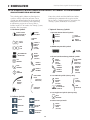
3.2 VECTRA GENISYS, INTELECT LEGEND XT AND INTELECT VET THERAPY SYSTEMS HARDWARE
AND SOFTWARE SYMBOL DEFINITIONS
Know the symbols and their definitions before
performing any operation of or service to the
Vectra Genisys, Intelect Legend XT or Intelect Vet
Therapy Systems, Modules, or Accessories.
The symbol graphics below are found on the
system as well as within the software. These
symbols are defined below for the purpose of
recognition and functionality when operating
or performing service on an Vectra Genisys,
Intelect Legend XT or Intelect Vet Therapy System,
Modules, and Accessories.
A. Hardware Symbols
CONTRAST CONTROL
NOT FUNCTIONAL ON
GENISYS SYSTEMS
C. Optional Accessory Symbols
1. Operator Remote Control Symbols
CLINICAL
RESOURCES
INCREASE
INTENSITY
BACK
ON/OFF
SWITCH
DATA
PORT
MULTIMEDIA AND
PATIENT CARD
STOP
TREATMENT
DECREASE
INTENSITY
CHANNEL 1/2
OPERATOR
REMOTE
CONTROL
OPTIONAL
THERAPY
INTENSITY
CONTROL
HOME
M
MANUAL
STIMULATION
2. NiMH Battery Module Symbols
BATTERY
CHARGING
CHARGE LEVEL
PATIENT
INTERRUPT
SWITCH
OPTIONAL
3. Channel 3/4 Electrotherapy Module Symbols
PATIENT
INTERRUPT
SWITCH
OPTIONAL
CHANNEL 3
LEAD WIRES
CHANNEL 1
LEAD WIRES
PAUSE
TREATMENT
START
TREATMENT
PAUSE
TREATMENT
CHANNEL 2
LEAD WIRES
CHANNEL 4
LEAD WIRES
MICROCURRENT
PROBE
INACTIVE ON
INTELECT VET
CHANNEL 3/4
OPERATOR
REMOTE|
CONTROL
OPTIONAL
4. Laser Module Symbols (Genisys Only)
MICROCURRENT
PROBE
INACTIVE ON
INTELECT VET
PATIENT
INTERRUPT
SWITCH
OPTIONAL
TREATMENT
ROOM INTERLOCK
CONNECTOR
ULTRASOUND
APPLICATOR
POINT
LOCATOR
INACTIVE
LASER
APPLICATOR
5. Laser Applicator Symbols (Genisys Only)
PAUSE
TREATMENT
B. Software Symbols
MOVE UP
MOVE LEFT
6. Patient Interrupt Switch
MOVE DOWN
ACCEPT AND
RETURN
PATIENT
INTERRUPT
SWITCH
OPTIONAL
MOVE RIGHT
DO NOT ACCEPT
AND RETURN
17
Vectra Genisys®/Intelect Legend XT®/ Intelect® Vet Therapy Systems
4 SPECIFICATIONS
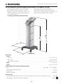
4.1 VECTRA GENISYS, INTELECT LEGEND XT AND INTELECT VET THERAPY SYSTEMS
HEIGHT
CART ONLY
HEIGHT
WITH SYSTEM & SYSTEM WITH MODULE
Refer to this section when performing
troubleshooting, replacement, and repair of a
Vectra Genisys, Intelect Legend XT and Intelect Vet
Therapy System, Modules, and Accessories.
The specifications found in this section provide
physical details of the Vectra Genisys, Intelect
Legend XT and Intelect Vet Therapy Systems. This
section also provides waveform specifications to
aid in troubleshooting.
A. Therapy Systems Physical Specifications
DEPTH
WIDTH
FIGURE 4.1
Dimensions
Height
Cart Only . . . . . . . . . . . . . . . . . . . . . . . . . . . . . . . . . . . . . . . . . . . . . . . . . . . . . . . . . . . . . . . . . . . . . . . . . . . . . . . . . . . . . . . . 33.75 in (85.7 cm)
With System . . . . . . . . . . . . . . . . . . . . . . . . . . . . . . . . . . . . . . . . . . . . . . . . . . . . . . . . . . . . . . . . . . . . . . . . . . . . . . . . . . . . . . 42.50 in (108 cm)
With System and Module . . . . . . . . . . . . . . . . . . . . . . . . . . . . . . . . . . . . . . . . . . . . . . . . . . . . . . . . . . . . . . . . . . . . . . 44.25 in (112.4 cm)
Width . . . . . . . . . . . . . . . . . . . . . . . . . . . . . . . . . . . . . . . . . . . . . . . . . . . . . . . . . . . . . . . . . . . . . . . . . . . . . . . . . . . . . . . . . . . . . . . . 17 in (43.2 cm)
Depth . . . . . . . . . . . . . . . . . . . . . . . . . . . . . . . . . . . . . . . . . . . . . . . . . . . . . . . . . . . . . . . . . . . . . . . . . . . . . . . . . . . . . . . . . . . . . 16.25 in (41.3 cm)
Power (Combination and Electrotherapy Systems)
Input . . . . . . . . . . . . . . . . . . . . . . . . . . . . . . . . . . . . . . . . . . . . . . . . . . . . . . . . . . . . . . . . . . . . . . . . . . . . . 100 - 240 V - 175 VA, 50/60 Hz
Output (Internal Power Supply) . . . . . . . . . . . . . . . . . . . . . . . . . . . . . . . . . . . . . . . . . . . . . . . . . . . . . . . . . . . . . . . . . . . . . . . .+24, 7.3 A
Electrical Class . . . . . . . . . . . . . . . . . . . . . . . . . . . . . . . . . . . . . . . . . . . . . . . . . . . . . . . . . . . . . . . . . . . . . . . . . . . . . . . . . . . . . . . . . . . CLASS I
Mode of Operation . . . . . . . . . . . . . . . . . . . . . . . . . . . . . . . . . . . . . . . . . . . . . . . . . . . . . . . . . . . . . . . . . . . . . . . . . . . . . . . . . . Continuous
Electrical Type
Ultrasound (Combination Systems Only) and Laser Module (Vectra Genisys and Intelect Vet Only) . . . . TYPE B
Electrotherapy, sEMG and Channel 3/4 Module. . . . . . . . . . . . . . . . . . . . . . . . . . . . . . . . . . . . . . . . . . . . . . . . . . . . . . TYPE BF
18
Vectra Genisys®/Intelect Legend XT®/ Intelect® Vet Therapy Systems
4 SPECIFICATIONS
4.2 ELECTROTHERAPY WAVEFORM SPECIFICATIONS
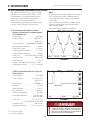
The specifications found in this section provide
the necessary waveform specifications to aid in
troubleshooting. A waveform graphic from an
oscilloscope is also provided for clarification.
Refer to this section when performing
troubleshooting, replacement, and repair of the
Therapy System, Modules, and Accessories.
NOTE:
All waveforms, except High Voltage Pulsed Current
(HVPC), of the Vectra Genisys, Intelect Legend XT
and Intelect Vet Therapy Systems have a 200 mA
current limit.
VMS™, VMS™ Burst, and all TENS waveform output
intensities are measured, specified, and listed to
peak, not peak to peak.
All waveforms are available on all channels.
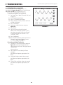
A. IFC (Interferential) Traditional (4 Pole)Figure 4.2 (Vectra Genisys, Intelect Legend
XT, and Intelect Vet)
Output Mode . . . . . . . . . . . . . . . . . . . . . . . Electrodes
Output Intensity . . . . . . . . . . . . . . . . 0-100 mA(CC)
0-100 V (CV)
Carrier Frequency . . . .2,500, 4,000, and 5,000 Hz
Beat Frequency (Sweep Off ) . . . . . . . . . .1-200 Hz
Sweep Time (Fixed) . . . . . . . . . . . . . . . . 15 seconds
Sweep Low Beat Frequency . . . . . . . . . .1-199 Hz
Sweep High Beat Frequency . . . . . . . . . .2-200 Hz
Vector Scan . . . . . . . Off, Manual, 40%, and 100%
Treatment Time . . . . . . . . . . . . . . . . . . 1-60 Minutes
Mode Selection. . . . . . . . . . . . . . . . . . . . . CC or CV*
(Intelect Vet Mode Selection Fixed- CV only)
Available on Channels . . . . . .1 & 2, 3 & 4 Option
FIGURE 4.2
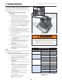
B. TENS- Asymmetrical Biphasic- Figure 4.3
(Vectra Genisys)
Output Mode . . . . . . . . . . . . . . . . . . . . . . . Electrodes
Output Intensity . . . . . . . . . . . . . . . . 0-110 mA (CC)
0-110 V (CV)
Phase Duration . . . . . . . . . . . . . . . . . .20-1,000 μsec
Frequency . . . . . . . . . . . . . . . . . . . . . . . . . . . .1-250 Hz
Mode Selection. . . . . . . . . . . . . . . . . . . . . CC or CV*
Burst Frequency . . . . . . . . . . . . . . . . . . . . . . 0-10 bps
Frequency Modulation . . . . . . . . . . . . . . .0-250 Hz
Amplitude Modulation . . . . . . . . . .Off, 40%, 60%,
80%, and 100%
Cycle Time . . . . . . . . . . . . . . . . . . . .4/4, 4/8, 7/7, 5/5,
4/12, 10/10, 10/20, 10/30, 10/50
Treatment Time . . . . . . . . . . . . . . . . . . 1-60 minutes
Available on Channels . . . . . .1 & 2, 3 & 4 Option
FIGURE 4.3
Stimulus delivered by the TENS waveforms of this device, in certain
configurations, will deliver a charge of 25 microcoulombs (μC) or
greater per pulse and may be sufficient to cause electrocution.
Electrical current of this magnitude must not flow through the
thorax because it may cause a cardiac arrhythmia.
*CC= Constant Current
CV= Constant Voltage
19
Vectra Genisys®/Intelect Legend XT®/ Intelect® Vet Therapy Systems
4 SPECIFICATIONS
4.2 ELECTROTHERAPY WAVEFORM SPECIFICATIONS (CONTINUED)
C. TENS- Symmetrical Biphasic- Figure 4.4
(Vectra Genisys, and Intelect Legend XT)
Output Mode . . . . . . . . . . . . . . . . . . . . . . . Electrodes
Output Intensity . . . . . . . . . . . . . . . . . 0-80 mA (CC)
0-80 V (CV)
Phase Duration . . . . . . . . . . . . . . . . . .20-1,000 μsec
Frequency . . . . . . . . . . . . . . . . . . . . . . . . . . . .1-250 Hz
Mode Selection. . . . . . . . . . . . . . . . . . . . . CC or CV*
Burst Frequency . . . . . . . . . . . . . . . . . . . . . . 0-10 bps
Frequency Modulation . . . . . . . . . . . . . . .0-250 Hz
Amplitude Modulation . . . . . . . . . .Off, 40%, 60%,
80%, and 100%
Cycle Time . . . . . . . . . . . . . . . . . . . .4/4, 4/8, 7/7, 5/5,
4/12, 10/10, 10/20, 10/30, 10/50
Treatment Time . . . . . . . . . . . . . . . . . . 1-60 minutes
Available on Channels . . . . . .1 & 2, 3 & 4 Option
FIGURE 4.4
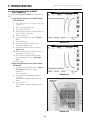
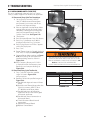
D. High Voltage Pulsed Current (HVPC)Figure 4.5 (Vectra Genisys, Intelect Legend
XT, and Intelect Vet)
Output Mode . . . . . . . . . . . . . . Electrodes or Probe
Output Intensity . . . . . . . . . . . . . . . . . . . . . . . 0-500 V
Polarity . . . . . . . . . . . . . . . . . . . Positive or Negative
Ramp . . . . . . . . . . . . . . . . 0.5 sec, 1 sec, 2 sec, 5 sec
Display . . . . . . . . . . . . . . . . . . .Peak Current or Volts
Sweep . . . . . . . . . . . . . . . . Continuous, 80/120 pps,
1/120 pps, 1/10 pps
Frequency . . . . . . . . . . . . . . . . . . . . . . . . . . 10-120 Hz
Cycle Time . . . . . . . . . . . . . . Continuous, 5/5, 4/12,
10/10, 10/20, 10/30, 10/50
Treatment Time . . . . . . . . . . . . . . . . . . 1-60 Minutes
Anti-Fatique . . . . . . . . . . . . . . . . . . . . . . . . . Off or On
Available on Channels . . . . . .1 & 2, 3 & 4 Option
FIGURE 4.5
*CC= Constant Current
CV= Constant Voltage
20
Vectra Genisys®/Intelect Legend XT®/ Intelect® Vet Therapy Systems
4 SPECIFICATIONS
4.2 ELECTROTHERAPY WAVEFORM SPECIFICATIONS (CONTINUED)
E. VMS™- Figure 4.6 (Vectra Genisys, and
Intelect Vet)
Output Mode . . . . . . . . . . . . . . . . . . . . . . . Electrodes
Output Intensity. . . . . . . . . . . . . . . . . . . . .0-200 mA (CC)
0-200 V (CV)
Channel Mode . . . . Single, Reciprocal, Co-Contract
Phase Duration . . . . . . . . . . . . . . . . . . . . . . . . 20-400 μsec
Mode Selection . . . . . . . . . . . . . . . . . . . . . . . . . CC or CV*
Anti-Fatigue . . . . . . . . . . . . . . . . . . . . . . . . . . . . . . Off or On
Set Intensity . .Individual Channel Intensity Setting
in Reciprocal and Co-Contract modes
Cycle Time . . . . . . . . . . . . . . . . . .Continuous, 5/5, 4/12,
10/10, 10/20, 10/30, 10/50
Frequency . . . . . . . . . . . . . . . . . . . . . . . . . . . . . . . 1-200 pps
Ramp . . . . . . . . . . . . . 0.5 sec, 1 sec, 2 sec, and 5 sec
Treatment Time . . . . . . . . . . . . . . . . . . 1-60 minutes
Available on Channels . . . . . .1 & 2, 3 & 4 Option
FIGURE 4.6
F. IFC (Interferential) Premodulated (2p)Figure 4.7 (Vectra Genisys, Intelect Legend
XT and Intelect Vet)
Output Mode . . . . . . . . . . . . . . . . . . . . . . . Electrodes
Output Intensity . . . . . . . . . . . . . . . . 0-100 mA(CC)
0-100 V (CV)
Carrier Frequency (Fixed) . . . . . . . . . . . . . 2,500 Hz
Beat Frequency (Sweep Off ) . . . . . . . . . .1-200 Hz
Sweep Time (Fixed) . . . . . . . . . . . . . . . . 15 seconds
Sweep Low Beat Frequency . . . . . . . . . .1-199 Hz
Sweep High Beat Frequency . . . . . . . . . .2-200 Hz
Vector Scan . . . . . . . Off, Manual, 40%, and 100%
Treatment Time . . . . . . . . . . . . . . . . . . 1-60 Minutes
Mode Selection. . . . . . . . . . . . . . . . . . . . . CC or CV*
(Intelect Vet Mode Selection Fixed- CC only)
Available on Channels . . . . . .1 & 2, 3 & 4 Option
FIGURE 4.7
*CC= Constant Current
CV= Constant Voltage
21
Vectra Genisys®/Intelect Legend XT®/ Intelect® Vet Therapy Systems
4 SPECIFICATIONS
4.2 ELECTROTHERAPY WAVEFORM SPECIFICATIONS (CONTINUED)
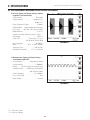
G. Russian- Figure 4.8 (Vectra Genisys, Intelect
Legend XT and Intelect Vet)
Output Mode . . . . . . . . . . . . . . . . . . . . . . Electrodes
Output Intensity . . . . . . . . . . . . . . . . . . . .0-100 mA (CC)
0-100 V (CV)
Carrier Frequency (Fixed) . . . . . . . . . . . . . 2,500 Hz
Channel Mode . . . . Single, Reciprocal, Co-Contract
Duty Cycle . . . . . 10%, 20%, 30%, 40%, and 50%
Mode Selection . . . . . . . . . . . . . . . . . . . . . . . . . CC or CV*
(Intelect Vet Mode Selection Fixed- CC only)
Anti-Fatigue . . . . . . . . . . . . . . . . . . . . . . . . . . . . . . Off or On
Cycle Time . . . . . . . . . . . . . Continuous, 5/5, 4/12,
10/10, 10/20, 10/30, 10/50
Burst Frequency . . . . . . . . . . . . . . . . . . . 20-100 bps
Ramp . . . . . . . . . . . . . . . . . 0.5, 1, 2, and 5 seconds
Treatment Time . . . . . . . . . . . . . . . . . 1-60 minutes
Available on Channels . . . . . .1 & 2, 3 & 4 Option
FIGURE 4.8
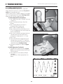
H. Microcurrent- Figure 4.9 (Vectra Genisys
and Intelect Legend XT)
Output Mode . . . . . . . . . . . . . Electrodes or Probe
Output Intensity . . . . . . . . . . . . . . . . . . . . . . 5-1000.0 μA
Polarity . . . . . . .Positive, Negative, or Alternating
Treatment Time . . . . . 1-60 Minutes (Electrodes)
1-60 Seconds (Probe)
Carrier Frequency . . . . . . . . . . . . . . . . 0.1- 1000 Hz
Duty Cycle (Fixed) . . . . . . . . . . . . . . . . . . . . . . . . 50%
Ramp (Fixed) . . . . . . . . . . . . . . . . . . . . . . . . 1 second
FIGURE 4.9
*CC= Constant Current
CV= Constant Voltage
22
Vectra Genisys®/Intelect Legend XT®/ Intelect® Vet Therapy Systems
4 SPECIFICATIONS
4.2 ELECTROTHERAPY WAVEFORM SPECIFICATIONS (CONTINUED)
I. VMS™ Burst- Figure 4.10 (Vectra Genisys)
Output Mode . . . . . . . . . . . . . . . . . . . . . . . Electrodes
Output Intensity. . . . . . . . . . . . . . . . . . . . .0-200 mA (CC)
0-200 V (CV)
Channel Mode . . . . Single, Reciprocal, Co-Contract
Phase Duration . . . . . . . . . . . . . . . . . . . . . . . . 20-400 μsec
Mode Selection . . . . . . . . . . . . . . . . . . . . . . . . . CC or CV*
Anti-Fatigue . . . . . . . . . . . . . . . . . . . . . . . . . . . . . . Off or On
Set Intensity . .Individual Channel Intensity Setting
in Reciprocal and Co-Contract modes
Cycle Time . . . . . . . . . . . . . . . . . .Continuous, 5/5, 4/12,
10/10, 10/20, 10/30, 10/50
Frequency . . . . . . . . . . . . . . . . . . . . . . . . . . . . . . . 1-200 pps
Ramp . . . . . . . . . . . . . 0.5 sec, 1 sec, 2 sec, and 5 sec
Treatment Time . . . . . . . . . . . . . . . . . . 1-60 minutes
Available on Channels . . . . . . 1 & 2, 3 & 4 Option
FIGURE 4.10
J. DC (Direct Current)- Figure 4.11 (Vectra
Genisys)
Output Mode . . . . . . . . . . . . . . . . . . . . . . .Electrodes
Output Intensity. . . . . . . . . . . . . . . . . . . . . . . . 0-4 mA
Polarity Reversal . . . . . . . . . . . . . . . . . . . . . .On or Off
With Polarity Reversal On, Polarity will change
after 50% of treatment time.
Cycle Time . . . . . . . . . . . . Continuous, 5/60, 10/60
Treatment Time . . . . . . . . . . . . . . . . . . 1-10 minutes
Mode Selection (Fixed) . . . . . . . . . . . . . . . . . . . . . . . . . CC*
Available on Channels . . . . . . 1 & 2, 3 & 4 Option
FIGURE 4.11
K. Iontophoresis- (Intelect Vet)
Output Mode . . . . . . . . . . . . . . . . . . . . . . .Electrodes
Output Intensity. . . . . . . . . . . . . . . . . . . . . . . . 0-4 mA
Calculated Dosage . . . . . . . . . 40-80 mA - Minute
Mode Selection (Fixed) . . . . . . . . . . . . . . . . . . . . . . . . . CC*
Available on Channels . . . . . . 1 & 2, 3 & 4 Option
*CC= Constant Current
CV= Constant Voltage
23
Vectra Genisys®/Intelect Legend XT®/ Intelect® Vet Therapy Systems
4 SPECIFICATIONS
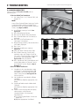
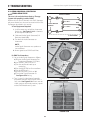
4.3 ULTRASOUND SPECIFICATIONS
This section provides the necessary Ultrasound
Specifications to aid in troubleshooting the
Vectra Genisys, Intelect Legend XT or Intelect Vet
Ultrasound PC Board and Applicators.
1 cm2
Refer to these specifications as necessary when
troubleshooting the Ultrasound PC Board and
Applicators.
5 cm2
STANDARD
2 cm2
10 cm2
Ultrasound
Frequency . . . . . . . . . . . . . . . . . . . . . . . . . . . . . . . . . . . . . . . . . . . . . . . . . . . . . . . . . . . . . . . . . . . . . . 1 MHz, ± 5%; 3.3 MHz, ±5%
Duty Cycles . . . . . . . . . . . . . . . . . . . . . . . . . . . . . . . . . . . . . . . . . . . . . . . . . . . . . . . . . . . . . . . . 10%, 20%, 50%, and Continuous
Pulse Frequency. . . . . . . . . . . . . . . . . . . . . . . . . . . . . . . . . . . . . . . . . . . . . . . . . . . . . . . . . . . . . . . . . . . . . . . . . . . . . . . . . . . . . . 100 Hz
Pulse Duration . . . . . . . . . . . . . . . . . . . . . . . . . . . . . . . . . . . . . . . . . . . . 1 mSec, ±20%; 2 mSec, ±20%, and 5 mSec, ±20%
Output Power
10 cm2 Crystal . . . . . . . . . . . . . . . . . . . . . . . . . . . . . . . . . . . . . . . . . . . . . . .0-20 Watts at 1 MHz and 0-10 Watts at 3.3 MHz
5 cm2 Crystal . . . . . . . . . . . . . . . . . . . . . . . . . . . . . . . . . . . . . . . . . . . . . . . . . . . . . . . . . . . . . . . . . . . . . .0-10 Watts, 1 and 3.3 MHz
2 cm2 Crystal . . . . . . . . . . . . . . . . . . . . . . . . . . . . . . . . . . . . . . . . . . . . . . . . . . . . . . . . . . . . . . . . . . . . . . . 0-4 Watts, 1 and 3.3 MHz
1 cm2 Crystal . . . . . . . . . . . . . . . . . . . . . . . . . . . . . . . . . . . . . . . . . . . . . . . . . . . . . . . . . . . . . . . . . . . . . . . . 0-2 Watts 3.3 MHz Only
Amplitude . . . . . . . . . . . . . . . . . . . . . . . . . . . . . . . . . . . . . . . . . . . . . . . . . . . . . . . . . . . . . 0 to 2.5 w/cm2 in continuous mode,
0-3 w/cm2 in pulsed modes
Output accuracy . . . . . . . . . . . . . . . . . . . . . . . . . . . . . . . . . . . . . . . . . . . . . . . . . . . . . . . . . . . . ± 20% above 10% of maximum
Temporal Peak to Average Ratios: . . . . . . . . . . . . . . . . . . . . . . . . . . . . . . . . . . . . . . . . . . . . . 2:1, ± 20%, at 50% Duty Cycle
5:1, ± 20%, at 20% Duty Cycle
9:1, ± 20%, at 10% Duty Cycle
Beam Nonuniformity Ratio. . . . . . . . . . . . . . . . . . . . . . . . . . . . . . . . . . . . . . . . . . . . . . . . . . . . . . . . . . . . . . . . . 5.0 : 1 maximum
Beam Type . . . . . . . . . . . . . . . . . . . . . . . . . . . . . . . . . . . . . . . . . . . . . . . . . . . . . . . . . . . . . . . . . . . . . . . . . . . . . . . . . . . . . . Collimating
IPX0 Rating for Unit . . . . . . . . . . . . . . . . . . . . . . . . . . . . . . . . . . . . . . . . . . . . . . . . . . . . . . . . . . . . . . . . . . . . . . . . . . . . . . . . . . . . .IPX0
IPX7 Rating for Applicator . . . . . . . . . . . . . . . . . . . . . . . . . . . . . . . . . . . . . . . . . . . . . . . . . . . . . . . . . . . . . . . . . . . . . . . . . . . . . . .IPX7
Effective Radiating Areas . . . . . . . . . . . . . . . . . . . . . . . . . . . . . . . . . . . . . . . . . . . . . . . . . . . . . . 0 cm2 Crystal: 6.8 cm2 – 10 cm2
5 cm2 Crystal: 3.5 cm2 – 5 cm2
2 cm2 Crystal: 1.4 cm2 – 2 cm2
1 cm2 Crystal: 0.7 cm2 – 1 cm2
Treatment Time. . . . . . . . . . . . . . . . . . . . . . . . . . . . . . . . . . . . . . . . . . . . . . . . . . . . . . . . . . . . . . . . . . . . . . . . . . . . . . . . . . . . . . .1-30 Minutes
Head Warming Feature
The Head Warming feature of an Vectra Genisys, Intelect Legend XT or Intelect Vet Combination Therapy System
utilizes Ultrasound output resulting in warming of the Sound Head to increase patient comfort.
With Head Warming enabled, ultrasound is emitted without pressing the Start button. The Applicator LED will not
illuminate during the Head Warming period. US Channel will indicate "Head Warming".
Output . . . . . . . . . . . . . . . . . . . . . . . . . . . . . . . . . . . . . . . . . . . . . . . . . . . . . . . . . . . . . . . . . . . . . . . .0 - 50% Cycling of maximum power
Frequency . . . . . . . . . . . . . . . . . . . . . . . . . . . . . . . . . . . . . . . . . . . . . . . . . . . . . . . . . . . . . . . . . . . . . . . . . . . . . . . . . . . . . . . . . . . . . . . . . 3.3 Mhz
Sound Head Temperature . . . . . . . . . . . . . . . . . . . . . . . . . . . . . . . . . . . . . . . . . . . . . . . . . . . . . . . . . 85 °F - 110 °F (29.4 °C - 43.3 °C)
24
Vectra Genisys®/Intelect Legend XT®/ Intelect® Vet Therapy Systems
4 SPECIFICATIONS
4.4 DESCRIPTION OF DEVICE MARKINGS
The markings on the Vectra Genisys Therapy System, the Intelect Legend XT Therapy System and the Intelect Vet
Therapy System are your assurance of their conformity to the highest applicable standards of medical equipment
safety and electromagnetic compatibility. One or more of the following markings may appear on these devices:
EU Directive on Waste Electrical and
Electronic Equipment (WEEE) ensures that
product is appropriately disposed of or
recycled at the end of its life.
Listed by Intertek Testing Services NA Inc.
9700675
Conforms to UL Standard UL/IEC/EN
60601-1, IEC/EN 60601-1-2, IEC 60601-2-5,
IEC 60601-2-10
Certified to CAN/CSA Standard C22.2 No.
601.1-M90 w/A2
Refer to Instruction Manual/Booklet
Equipment capable of delivering output
values in excess of 10 mA r.m.s. or 10V r.m.s.
averaged over any period of 5 s
Type B Equipment
Type BF Equipment
Protected Earth
Dangerous Voltage
Non-Ionizing Radiation
25
Vectra Genisys®/Intelect Legend XT®/ Intelect® Vet Therapy Systems
4 SPECIFICATIONS
4.5 LASER MODULE SPECIFICATIONS VECTRA GENISYS AND INTELECT VET
This section provides the necessary Laser
Module and Applicator Specifications to aid in
troubleshooting.
Refer to these specifications as necessary when
troubleshooting the Laser Module and Applicators.
Power Input . . . . . . . . . . . . . . . . . . . . . . . . . . . . . . . . . . . . . . . . . . . . . . . . . . . . . . . . . . . . . . . . . . . . . . . . . . .Therapy System Dependent
Output to Laser Applicators . . . . . . . . . . . . . . . . . . . . . . . . . . . . . . . . . . . . . . . . . . . . . . . . . . . . . . . . . . . Per Applicator Requirement
NOTE:
No Field Service is applicable to the Laser Module or
Laser Applicators. All Laser Modules and Applicators
suspected to require service or calibration must be
sent to the factory.
• DO NOT point the laser beam directly into
human or animal eyes. The lens of the eye
does not detect the invisible, coherent laser
beams, potentially resulting in permanent
retinal damage.
• Class 3B Lasers are considered an acute hazard
to the skin and eyes from direct radiation.
Eye injury will occur if laser is viewed directly
or from specular reflection. Laser protective
eyewear is required for all persons in the
treatment area.
• Approved Laser protective eyewear must be
worn at all times by all persons in the vicinity
when the Laser is On.
26
Vectra Genisys®/Intelect Legend XT®/ Intelect® Vet Therapy Systems
4 SPECIFICATIONS
4.6 LASER APPLICATOR SPECIFICATIONS VECTRA GENISYS AND INTELECT VET
A. Single Diode Applicators
NOTE:
No Field Service is applicable to the Laser Module or
Laser Applicators. All Laser Modules and Applicators
suspected to require service or calibration must be
sent to the factory.
Single Diode Laser and LED Applicators
Applicator
850 nm 100 mW
850 nm 200 mW
820 nm 300 mW
820 nm 500 mW
Wavelength
(nm)
850
850
820
820
Output Power
(mW)
100
200
300
500
Power Density
(W/cm2)
1.43
2.86
0.606
1.01
Contact Area
(cm2)
0.07
0.07
0.495
0.495
Diode
Type
LASER
LASER
LASER
LASER
For all single diode and cluster laser and LED applicators, the expected increase in the measured quantities after
manufacture added to the values measured at the time of manufacture is ±20%.
Light Spectrum
IR
UV
400 nm
500 nm
600 nm
Visible Light
27
700 nm
Vectra Genisys®/Intelect Legend XT®/ Intelect® Vet Therapy Systems
4 SPECIFICATIONS
4.6 LASER APPLICATOR SPECIFICATIONS VECTRA GENISYS AND INTELECT VET (CONTINUED)
B. 9, 13, and 19 Diode Applicators
NOTE:
No Field Service is applicable to the Laser Module
or Laser Applicators. All Laser Applicators suspected
to require service or calibration must be sent to the
factory.
9 and 13 Diode Cluster Applicators
Applicator
Output Power
(mW)
Power Density
(W/cm2)
Contact Area
(cm2)
540 mW 9 Diode Cluster
540
0.072
7.55
1040 mW 9 Diose
Cluster
1040
0.135
7.55
415 mW 13 Diode
Cluster
415
0.055
7.55
715 mW 13 Diode
Cluster
715
0.095
7.55
Diode
Specifications
4- 670 nm (10 mW) LED
5- 850 nm (100 mW) LASER
4- 670 nm (10 mW) LED
5- 850 nm (200 mW) LASER
7- 670 nm (10 mW) LED
3- 850 nm (100 mW) LASER
3- 950 nm (15 mW) SLD
7- 670 nm (10 mW) LED
3- 850 nm (200 mW) LASER
3- 950 nm (15 mW) SLD
For all Laser and LED applicators, the expected increase in the measured quantities, after manufacture, added to
the values measured at the time of manufacture is ±20%.
Light Spectrum
UV
400 nm
IR
500 nm
600 nm
Visible Light
28
700 nm
Vectra Genisys®/Intelect Legend XT®/ Intelect® Vet Therapy Systems
4 SPECIFICATIONS
4.6 LASER APPLICATOR SPECIFICATIONS VECTRA GENISYS AND INTELECT VET (CONTINUED)
C. 33 Diode Applicators
NOTE:
No Field Service is applicable to the Laser Module
or Laser Applicators. All Laser Applicators suspected
to require service or calibration must be sent to the
factory.
33 Diode Cluster Applicators
Applicator
Output Power
(mW)
Power Density
(W/cm2)
Contact Area
(cm2)
1440 mW 33 Diode
Cluster
1440
0.046
31.2
Diode
Specifications
12- 670 nm (10 mW) LED
8- 880 nm (25 mW) SLD
8- 950 nm (15 mW) SLD
5- 850 nm (200 mW) LASER
For all Laser and LED applicators, the expected increase in the measured quantities, after manufacture, added to
the values measured at the time of manufacture is ±20%.
Light Spectrum
UV
400 nm
IR
500 nm
600 nm
Visible Light
29
700 nm
Vectra Genisys®/Intelect Legend XT®/ Intelect® Vet Therapy Systems
5 TROUBLESHOOTING
5.1 THERAPY SYSTEM ERROR MESSAGES
A. The information provided below is intended to
aid in defining the Software Error Messages of the
Vectra Genisys, Intelect Legend XT or Intelect
Vet Therapy Systems. Once a particular Error
Message is defined the information will also list
probable causes and possible remedies.
No Board Level troubleshooting or Field Repair
Information is or will be provided by Chattanooga
Group for Field Repair of the Vectra Genisys,
Intelect Legend XT or Intelect Vet Therapy
System, Modules, or Accessories.
Error messages in the range of 100 to 199 are
primarily user definable and remedied by following
the instructions given by the Therapy System. Error
messages in the ranges of 200- 299 and 300-399,
require Technical Assistance.
NOTE:
No Field Service is applicable to the Laser Module
or Laser Applicators. All Laser Applicators suspected
to require service or calibration must be sent to the
factory.
Code
Number
Type
Message
Probable Cause
Possible Remedies
100
Warning
Overcurrent
A. Check Electrodes and Lead Wires. Make certain Lead Wires are not damaged and are properly
connected to the system. Make certain Lead Wires are properly connected to the Electrodes and
that electrodes are not damaged and are making proper contact with treatment area.
B. Replace Lead Wires and Electrodes
101
Warning
Shorted Lead Wires
A. Check Electrodes and Lead Wires. Make certain Lead Wires are not damaged and are properly
connected to the system. Make certain Lead Wires are properly connected to the Electrodes and
that electrodes are not damaged and are making proper contact with treatment area.
B. Replace Lead Wires and Electrodes
102
Warning
Bad Contact Quality
A. Make certain Electrodes are making proper contact with the treatment area.
B. Make certain Lead Wires are properly connected to Electrodes.
C. Replace Electrodes and Lead Wires.
103
Warning
Blank Patient ID
Properly enter Patient ID. Refer to Therapy System User Manual for Patient Data Card instructions.
104
Warning
1. Blank Protocol Name
2. Blank Sequence Name
Properly enter Protocol or Sequence Name. Refer to the appropriate section of the Therapy System
User Manual.
106
107
Warning
Warning
1. Attempting to delete factory set Sequence.
2. Attempting to delete Clinical Protocol.
Cannot delete factory set Clinical Protocols or factory set Sequences.
108
Warning
Attempting to save additional User Protocols or
Sequences after system memory has reached the
maximum allowed (200).
Delete some User Protocols or Sequences. Refer to appropriate section of the Therapy System User
Manual for instructions.
109
110
111
Warning
Warning
Warning
Attempting to access protocols or sequences and
none are found in the system.
A. User Protocols- No protocols have been saved in the system. Refer to Therapy System User
Manual to save User Protocols
B. Sequences- No User Sequences have been saved in the system. Refer to Therapy System User
Manual to save Sequences.
112
Warning
Ultrasound Applicator disconnected from system
during treatment session.
A. Connect Ultrasound Applicator to system.
B. If Ultrasound Applicator is connected, reset system by turning power switch Off and On.
C. If problem persists, connect a known good Ultrasound Applicator. If problem continues, contact
dealer or factory for service.
113
Warning
Attempting to perform Ultrasound treatment with no
Applicator connected to the system.
A. Connect the desired Ultrasound Applicator to the system.
B. If Ultrasound Applicator is connected, reset system by turning power switch Off and On.
C. If problem persists, connect a known good Ultrasound Applicator. If problem continues, contact
dealer or factory for service.
114
Warning
Ultrasound Applicator is not calibrated.
Attempt to use a known good Applicator. If problem continues, contact dealer or factory for service.
115
Warning
Ultrasound Applicator is too hot.
Allow Ultrasound Applicator Sound Head to cool to ambient temperature.
116
117
Warning
Warning
1. No Patient Data Card is inserted into the system.
2. Attempted to use an Invalid Patient Data Card.
A. Properly insert the Patient Data Card into the system port. Refer to Therapy System User Manual
for new and existing Patient Data Card instructions.
B. Attempt to use a known good Patient Data Card.
C. Make certain a Patient Data Card and not an sEMG Data Card is being used.
D. If problem continues, contact dealer or factory for service.
30
Vectra Genisys®/Intelect Legend XT®/ Intelect® Vet Therapy Systems
5 TROUBLESHOOTING
5.1 THERAPY SYSTEM ERROR MESSAGES (CONTINUED)
Code
Number
Type
Message
Probable Cause
Possible Remedies
118
Warning
Attempting to save additional User Protocols or Sequences after Delete some User Protocols or Sequences. Refer to appropriate section of the Therapy
system memory has reached the maximum allowed (200).
System User Manual for instructions.
119
120
121
122
Warning
Warning
Warning
Warning
1. Attempted to read a treatment from Patient Data Card that is
not a valid treatment for the system
2. Attempted to use a Non-Patient Data Card.
3. No Patient Data Card inserted into system port.
4. Unknown type of smart card inserted into system.
A. Use a Patient Data Card with proper treatment data for the system.
B. Properly insert a Patient Data Card.
C. Insert a known good Patient Data Card.
D. If problem persists, insert a known good Patient Data Card. If problem continues, contact
dealer or Factory for service.
123
Warning
Patient Data Card is full.
Erase Patient Data Card. Refer to Therapy System User Manual for instructions.
124
Warning
Patient Treatment Data already saved.
A. Cannot save same data again on Patient Data Card.
B. Use a new Patient Data Card to resave data.
C. Erase Patient Data Card and resave treatment data.
125
Warning
Multimedia Card (MMC) not in system port.
A. Properly insert the MMC card into the system port.
B. Insert a known good MMC Card. If problem continues, contact dealer or Chattanooga
Group for Service.
126
Warning
No valid channels are available for attempted treatment.
A. Complete existing treatment before attempting to start another.
B. Reset Therapy System by turning main power switch Off and On.
127
128
Warning
Warning
1. No sEMG Channels are available for treatment.
2. No sEMG Module installed or detected by system.
A. Wait until current treatment is complete.
B. Reset Therapy System by turning main power switch Off and On.
C. Make certain sEMG Module is properly installed. Refer to sEMG Module User Manual for
installation instructions.
D. Replace sEMG Module with known good sEMG Module.
E. If problem continues, contact dealer or factory for service.
129
Warning
sEMG Data Card full.
A. sEMG Data Card faulty. Insert a known good sEMG Data Card. If problem continues,
contact dealer or factory for service.
130
Warning
Another treatment is running while attempting to set up and
perform a Laser Therapy treatment.
A. Allow existing treatment to complete before starting Laser Therapy.
B. If no other treatment is running, reset Therapy System by turning main power switch
Off and On.
131
Warning
Treatment Room Door Lockout is breached.
A. Make certain Treatment Room Door is completely closed.
B. Make certain the Lockout cable is connected to the system.
C. Replace Lockout to System cable with a known good cable.
D. Contact department responsible for installation of the Treatment Room Door Lockout
mechanism for maintenance or repair.
E. If problem continues, send Laser Module to factory for Service.
132
Warning
Attempted to start a laser treatment but noLaser Applicator is
plugged in.
A. Connect desired Laser Applicator to the system.
B. If Applicator is connected, reset Therapy System by turning main power switch Off and
On.
C. Connect a known good Laser Applicator.
D. If problem continues, send Laser Module to factory for Service.
133
Warning
Laser Applicator became unplugged while performing a laser
treatment.
A. Connect desired Laser Applicator to the system.
B. If Laser Applicator is connected, reset Therapy System by turning main power switch
Off and On.
C. Connect a known good Laser Applicator.
D. If problem continues, send Laser Module to factory for Service.
134
Warning
Entered incorrect laser PIN.
A. Enter correct Laser PIN number.
B. If problem continues, send Laser Module to factory for Service.
31
Vectra Genisys®/Intelect Legend XT®/ Intelect® Vet Therapy Systems
5 TROUBLESHOOTING
5.1 THERAPY SYSTEM ERROR MESSAGES (CONTINUED)
Code
Number
Type
Message
Probable Cause
Possible Remedies
135
Warning
Control Board Software upgrade warning.
Upgrade Control Board Software to latest version. Contact dealer or Chattanooga Group for latest
software upgrade and instructions.
136
Warning
Stim Board Main Software upgrade warning.
Upgrade Stim Board Software to latest version. Contact dealer or Chattanooga Group for latest
software upgrade and instructions.
137
Warning
Stim Board Main Software upgrade warning.
Upgrade Stim Board Software to latest version. Contact dealer or Chattanooga Group for latest
software upgrade and instructions.
138
Warning
Ultrasound Board Software upgrade warning.
Upgrade Ultrasound Board Software to latest version. Contact dealer or Chattanooga Group for
latest software upgrade and instructions.
139
Warning
Laser Board Software upgrade warning.
Upgrade Laser Board Software to latest version. Contact dealer or Chattanooga Group for latest
software upgrade and instructions.
140
Warning
MMC Software upgrade warning.
Upgrade MMC Software to latest version. Contact dealer or Chattanooga Group for latest software
upgrade and instructions.
141
Warning
Battery Module Software upgrade warning.
Upgrade Battery Software to latest version. Contact dealer or Chattanooga Group for latest
software upgrade and instructions.
142
Warning
A Laser Protocol was selected but no Laser Module is
installed on system.
Install Laser Module to Therapy System. Refer to Laser Module User Manual for installation
Instructions.
143
Warning
A Laser Protocol was selected but no Laser Applicator
connected to system.
A. Connect proper Laser Applicator to the system.
B. If Laser Applicator is connected, reset Therapy System by turning main power switch
Off and On.
C. Connect a known good Laser Applicator.
D. If problem continues, send Laser Module to factory for Service.
144
Warning
Wrong Laser Applicator connected to system for the
protocol selected.
A. Connect correct Laser Applicator to the system.
B. If Applicator is connected, reset Therapy System by turning main power switch Off and On.
C. Connect a known good Laser Applicator.
D. If problem continues, send Laser Module to factory for Service.
145
Warning
Patient Data Card button on Home Screen was pressed
with no Patient Data Card installed into system port and
no treatment currently being performed.
Properly insert a Patient Data Card, set up and perform the treatment and, save data to Patient
Data Card.
32
Vectra Genisys®/Intelect Legend XT®/ Intelect® Vet Therapy Systems
5 TROUBLESHOOTING
5.1 THERAPY SYSTEM ERROR MESSAGES (CONTINUED)
ERROR MESSAGES REQUIRING TECHNICAL ASSISTANCE 200299
Code
Number
Type
Message
Probable Cause
Possible Remedies
200
Error
Error reading the system Real Time Clock (RTC)
Replace Control Board
201
Error
Internal List Box Memory Error.
Reinstall software. If problem persists, replace Control Board.
202
Error
Program Control Software Allocation Memory Error
Reinstall software. If problem persists, replace Control Board.
203
Error
Error erasing Patient Data Card
Insert known good Patient Data Card. If problem persists, replace Control Board.
204
Error
Error writing to sEMG Data Card.
Insert known good sEMG Data Card. If problem persists, replace Control Board.
205
Error
MMC Card Formatting Error.
(Using Tech Service Utilities)
Insert known good MMC Card. If problem persists, replace Control Board.
206
Error
Error reading MMC.
Insert known good MMC Card. If problem persists, replace Control Board.
207
Error
Error reading protocols on power up of system.
Restore default protocols. All User Protocols and Saved Sequences will be deleted
permanently from the system.
208
Error
Error reading protocols.
Restore default protocols. All User Protocols and Saved Sequences will be deleted
permanently from the system.
209
Error
Error writing protocol.
Restore default protocols. All User Protocols and Saved Sequences will be deleted
permanently from the system.
210
Error
Error Calibrating Ultrasound Applicator.
A. Connect a known good Ultrasound Applicator.
B. Replace Ultrasound Board.
C. Replace Control Board.
211
Error
Error saving Calibration Data to Ultrasound Applicator.
A. Connect a known good Ultrasound Applicator.
B. Replace Ultrasound Board.
C. Replace Control Board.
212
Error
Ultrasound Applicator not calibrated OK Error.
A. Connect a known good Ultrasound Applicator.
B. Replace Ultrasound Board.
C. Replace Control Board.
213
Error
Time out error saving Ultrasound Applicator
Calibration Data to Applicator.
A. Connect a known good Ultrasound Applicator.
B. Replace Ultrasound Board.
C. Replace Control Board.
214
Error
General Laser PC Board Error.
Send Laser Module to factory for Service.
215
Error
Laser Applicator out of calibration due to laser output
being too high.
Send Laser Applicator to factory for Service.
216
Error
Laser Applicator out of calibration due to laser output
being too low.
Send Laser Applicator to factory for Service.
217
Error
Laser Applicator out of Calibration Due to LED output
being too high.
Send Laser Applicator to factory for Service.
218
Error
Laser Applicator out of Calibration Due to LED output
being too low.
Send Laser Applicator to factory for Service.
219
Error
Error while performing a Software upgrade.
A. Turn Therapy System Off and back On. Reattempt upgrade.
B. Replace the PC Board that the software is attempting to upgrade.
220
Error
Error while performing a Software upgrade.
A. Turn Therapy System Off and back On. Reattempt upgrade.
B. Replace the PC Board that the software is attempting to upgrade.
221
Error
Error while performing a Software upgrade.
A. Turn Therapy System Off and back On. Reattempt upgrade.
B. Replace the PC Board that the software is attempting to upgrade.
222
Error
Error while performing a Software upgrade.
A. Turn Therapy System Off and back On. Reattempt upgrade.
B. Replace the PC Board that the software is attempting to upgrade.
223
Error
Error while performing a Software upgrade.
A. Turn Therapy System Off and back On. Reattempt upgrade.
B. Replace the PC Board that the software is attempting to upgrade.
33
Vectra Genisys®/Intelect Legend XT®/ Intelect® Vet Therapy Systems
5 TROUBLESHOOTING
5.1 THERAPY SYSTEM ERROR MESSAGES (CONTINUED)
ERROR MESSAGES REQUIRING TECHNICAL ASSISTANCE 200299
Code
Number
Type
Message
Probable Cause
Possible Remedies
224
Error
Error while performing a Software upgrade.
A. Turn Therapy System Off and back On. Reattempt upgrade.
B. Replace the PC Board that the software is attempting to upgrade.
225
Error
Error while performing a Software upgrade.
A. Turn Therapy System Off and back On. Reattempt upgrade.
B. Replace the PC Board that the software is attempting to upgrade.
226
Error
Error while performing a Software upgrade.
A. Turn Therapy System Off and back On. Reattempt upgrade.
B. Replace the PC Board that the software is attempting to upgrade.
227
Error
Error while performing a Software upgrade.
A. Turn Therapy System Off and back On. Reattempt upgrade.
B. Replace the PC Board that the software is attempting to upgrade.
228
Error
Error while performing a Software upgrade.
A. Turn Therapy System Off and back On. Reattempt upgrade.
B. Replace the PC Board that the software is attempting to upgrade.
229
Error
Error while performing a Software upgrade.
A. Turn Therapy System Off and back On. Reattempt upgrade.
B. Replace the PC Board that the software is attempting to upgrade.
230
Error
Error while performing a Software upgrade.
A. Turn Therapy System Off and back On. Reattempt upgrade.
B. Replace the PC Board that the software is attempting to upgrade.
231
Error
Error while performing a Software upgrade.
A. Turn Therapy System Off and back On. Reattempt upgrade.
B. Replace the PC Board that the software is attempting to upgrade.
232
Error
Error while performing a Software upgrade.
A. Turn Therapy System Off and back On. Reattempt upgrade.
B. Replace the PC Board that the software is attempting to upgrade.
233
Error
Error while performing a Software upgrade.
A. Turn Therapy System Off and back On. Reattempt upgrade.
B. Replace the PC Board that the software is attempting to upgrade.
234
Error
Error while performing a Software upgrade.
A. Turn Therapy System Off and back On. Reattempt upgrade.
B. Replace the PC Board that the software is attempting to upgrade.
235
Error
Error while performing a Software upgrade.
A. Turn Therapy System Off and back On. Reattempt upgrade.
B. Replace the PC Board that the software is attempting to upgrade.
236
Error
Error while performing a Software upgrade.
A. Turn Therapy System Off and back On. Reattempt upgrade.
B. Replace the PC Board that the software is attempting to upgrade.
237
Error
Error while performing a Software upgrade.
A. Turn Therapy System Off and back On. Reattempt upgrade.
B. Replace the PC Board that the software is attempting to upgrade.
238
Error
Error while performing a Software upgrade.
A. Turn Therapy System Off and back On. Reattempt upgrade.
B. Replace the PC Board that the software is attempting to upgrade.
239
Error
Error while performing a Software upgrade.
A. Turn Therapy System Off and back On. Reattempt upgrade.
B. Replace the PC Board that the software is attempting to upgrade.
240
Error
Error while performing a Software upgrade.
A. Turn Therapy System Off and back On. Reattempt upgrade.
B. Replace the PC Board that the software is attempting to upgrade.
NOTE:
Errors 219-231: after replacing the PC Board, and if the problem persists, send the Therapy System to the Factory
for Service.
Errors 233-240: after replacing the PC Board, and if the problem persists, send the Therapy System to the Factory
for Service.
If Errors 219-240 occur while attempting to upgrade Laser Software, send the Laser Module and Applicators to
the Factory for Service.
34
Vectra Genisys®/Intelect Legend XT®/ Intelect® Vet Therapy Systems
5 TROUBLESHOOTING
5.1 THERAPY SYSTEM ERROR MESSAGES (CONTINUED)
CRITICAL ERRORS DEMANDING TECHNICAL SERVICE 300399
Code
Number
Type
Message
Probable Cause
Possible Remedies
300
Critical Error
Stim Board not found on Power up.
A. On Therapy System, make certain internal Ribbon Cable is seated on Stim PC Board and Control
Board.
B. On Channel 3/4 Electrotherapy Module, make certain the Therapy System to Module Ribbon
Cable is seated in the Therapy System and on the Module.
C. If problem persists, replace appropriate Stim PC Board.
D. Replace Control Board.
301
Critical Error
Stim Board failed Power up self test.
A. On Therapy System, make certain internal Ribbon Cable is seated on Stim PC Board and Control
Board.
B. On Channel 3/4 Electrotherapy Module, make certain the Therapy System to Module Ribbon
Cable is seated in the Therapy System and on the Module.
C. If problem persists, replace appropriate Stim PC Board.
D. Replace Control Board.
302
Critical Error
Stim Board Reset occurred. But, neither the main uP
nor channel uP reset bit was set.
A. On Therapy System, make certain internal Ribbon Cable is seated on Stim PC Board and Control
Board.
B. On Channel 3/4 Electrotherapy Module, make certain the Therapy System to Module Ribbon
Cable is seated in the Therapy System and on the Module.
C. If problem persists, replace appropriate Stim PC Board.
D. Replace Control Board.
303
Critical Error
Main uP on Stim Board reset occurred.
A. On Therapy System, make certain internal Ribbon Cable is seated on Stim PC Board and Control
Board.
B. On Channel 3/4 Electrotherapy Module, make certain the Therapy System to Module Ribbon
Cable is seated in the Therapy System and on the Module.
C. If problem persists, replace appropriate Stim PC Board.
D. Replace Control Board.
304
Critical Error
Channel A uP on Stim Board reset occurred.
A. On Therapy System, make certain internal Ribbon Cable is seated on Stim PC Board and Control
Board.
B. On Channel 3/4 Electrotherapy Module, make certain the Therapy System to Module Ribbon
Cable is seated in the Therapy System and on the Module.
C. If problem persists, replace appropriate Stim PC Board.
D. Replace Control Board.
305
Critical Error
Channel B uP on Stim Board reset occurred.
A. On Therapy System, make certain internal Ribbon Cable is seated on Stim PC Board and Control
Board.
B. On Channel 3/4 Electrotherapy Module, make certain the Therapy System to Module Ribbon
Cable is seated in the Therapy System and on the Module.
C. If problem persists, replace appropriate Stim PC Board.
D. Replace Control Board.
306
Critical Error
Error writing to Stim Board.
A. On Therapy System, make certain internal Ribbon Cable is seated on Stim PC Board and Control
Board.
B. On Channel 3/4 Electrotherapy Module, make certain the Therapy System to Module Ribbon
Cable is seated in the Therapy System and on the Module.
C. If problem persists, replace appropriate Stim PC Board.
D. Replace Control Board.
307
Critical Error
Error writing from Stim Board.
A. On Therapy System, make certain internal Ribbon Cable is seated on Stim PC Board and Control
Board.
B. On Channel 3/4 Electrotherapy Module, make certain the Therapy System to Module Ribbon
Cable is seated in the Therapy System and on the Module.
C. If problem persists, replace appropriate Stim PC Board.
D. Replace Control Board.
35
Vectra Genisys®/Intelect Legend XT®/ Intelect® Vet Therapy Systems
5 TROUBLESHOOTING
5.1 THERAPY SYSTEM ERROR MESSAGES (CONTINUED)
CRITICAL ERRORS DEMANDING TECHNICAL SERVICE 300399
Code
Number
Type
Message
Probable Cause
Possible Remedies
308
Critical Error
Error reading from Stim Board.
A. On Therapy System, make certain internal Ribbon Cable is seated on Stim PC Board and Control
Board.
B. On Channel 3/4 Electrotherapy Module, make certain the Therapy System to Module Ribbon
Cable is seated in the Therapy System and on the Module.
C. If problem persists, replace appropriate Stim PC Board.
D. Replace Control Board.
309
Critical Error
Error reading from Stim Board.
A. On Therapy System, make certain internal Ribbon Cable is seated on Stim PC Board and Control
Board.
B. On Channel 3/4 Electrotherapy Module, make certain the Therapy System to Module Ribbon
Cable is seated in the Therapy System and on the Module.
C. If problem persists, replace appropriate Stim PC Board.
D. Replace Control Board.
310
Critical Error
Ultrasound Board has reported an error.
A. Make certain Ultrasound PC Board is completely seated on internal Header and Ribbon Cable is
seated on Stim PC Board and Control Board.
B. If problem persists, replace Ultrasound PC Board.
C. Replace Control Board .
311
Critical Error
Ultrasound Board has reset.
A. Make certain Ultrasound PC Board is completely seated on internal Header and Ribbon Cable is
seated on Stim PC Board and Control Board.
B. If problem persists, replace Ultrasound PC Board.
C. Replace Control Board .
312
Critical Error
Error writing to Ultrasound Board.
A. Make certain Ultrasound PC Board is completely seated on internal Header and Ribbon Cable is
seated on Stim PC Board and Control Board.
B. If problem persists, replace Ultrasound PC Board.
C. Replace Control Board .
313
Critical Error
Error reading from Ultrasound Board.
A. Make certain Ultrasound PC Board is completely seated on internal Header and Ribbon Cable is
seated on Stim PC Board and Control Board.
B. If problem persists, replace Ultrasound PC Board.
C. Replace Control Board .
314
Critical Error
Error reading from Ultrasound Board.
A. Make certain Ultrasound PC Board is completely seated on internal Header and Ribbon Cable is
seated on Stim PC Board and Control Board.
B. If problem persists, replace Ultrasound PC Board.
C. Replace Control Board .
315
Critical Error
Error reading from Ultrasound Board.
A. Make certain Ultrasound PC Board is completely seated on internal Header and Ribbon Cable is
seated on Stim PC Board and Control Board.
B. If problem persists, replace Ultrasound PC Board.
C. Replace Control Board .
316
Critical Error
Error writing to Module Board.
A. Make certain the Therapy System to Module Ribbon Cable is seated in the Therapy System and
on the Module.
B. If problem persists, replace appropriate Stim PC Board.
C. Replace Control Board.
317
Critical Error
Error reading from Module Board.
A. Make certain the Therapy System to Module Ribbon Cable is seated in the Therapy System and
on the Module.
B. If problem persists, replace appropriate Stim PC Board.
C. Replace Control Board.
318
Critical Error
Error reading from Module Board.
A. Make certain the Therapy System to Module Ribbon Cable is seated in the Therapy System and
on the Module.
B. If problem persists, replace appropriate Stim PC Board.
C. Replace Control Board.
319
Critical Error
Error writing to Laser Board.
A. Replace Control Board.
B. Send Laser Module to factory for Service.
36
Vectra Genisys®/Intelect Legend XT®/ Intelect® Vet Therapy Systems
5 TROUBLESHOOTING
5.1 THERAPY SYSTEM ERROR MESSAGES (CONTINUED)
B. The information provided below is intended to
aid in additional troubleshooting of the Vectra
Genisys, Intelect Legend XT or Intelect Vet
Therapy Systems.
Problem
Channel 3/4 Module, Laser,
or NiMH Battery Module not
recognized.
Probable Cause
1. Bad connection between
System and Module.
2. Bad Module.
3. Bad Control Board.
sEMG Module not recognized.
NOTE:
No Field Service is applicable to the Laser Module
or Laser Applicators. All Laser Applicators suspected
to require service or calibration must be sent to the
factory.
1. Bad contact between Stim
Board and sEMG Module.
2. Bad sEMG Module.
3. Bad Stim Board.
4. Bad Control Board.
Possible Remedies
A. Make Certain Ribbon Cable is installed correctly and seated
completely.
B. If Battery or Laser, replace with known good module. If
Channel 3/4 Electrotherapy Module, make necessary repairs.
C. Replace Control Board.
A. Remove sEMG Module and make certain the stim board is
seated completely in the System housing. Check 1/4 Turn
Screw for proper installation.
B. Replace with known good sEMG Module.
C. Replace Stim Board.
D. Replace Control Board.
Operator Remote Control doesn’t
work according to User Manual
instructions.
1. Early Revision of Stim Board
and Connector Board.
2. Bad Operator Remote Control.
3. Bad Connector PC Board.
4. Bad Stim Board.
5. Bad Control Board.
A. Follow “Amendment to Operation” document shipped with Operator Remote.
B. Therapy System- Replace Stim Board with 27057 Rev. E or above and Connector Board with
27059 Rev E or above.
Channel 3/4 Electrotherapy Module- Replace Stim Board with 27057 Rev. E or above and
Connector Board with 27060 Rev F or above.
C. Replace with known good Operator Remote Control.
D. Replace Control Board.
Laser Module not functioning
after proper intallation has been
performed.
1. Therapy System Software not updated.
1. Update Therapy System Software to Version 2.0 or greater.
37
Vectra Genisys®/Intelect Legend XT®/ Intelect® Vet Therapy Systems
5 TROUBLESHOOTING
5.2 THERAPY SYSTEM TESTING
A. General
1. The following information is intended to aid
in troubleshooting the major components
of the Vectra Genisys, Intelect Legend XT
and Intelect Vet Therapy Systems to “Board
Level” only. These tests are FACTORY standard
testing procedures and methods used at
the factory before shipment of any Vectra
Genisys, Intelect Legend XT, or Intelect Vet
Therapy System.
2. Due to the complex nature of the technology
utilized by Chattanooga Group, the
recommended troubleshooting techniques
are to determine “Bad Board” and board
replacement only. No board component
level troubleshooting is recommended nor
will information or parts be supplied by
Chattanooga Group. Any board component
level troubleshooting performed will be at
sole risk and liability of the Service Technician
performing such troubleshooting techniques.
3. Once a particular PC Board has been
determined as bad, refer to the appropriate
Removal and Replacement Section of this
Manual for proper replacement.
B. Special Tools, Fixtures, & Materials Required
1. Certain tests require the use of special
tools and fixtures. These will be listed at
the particular test where they are required.
Testing with any other special tool or fixture
other than those stated could give erroneous
readings or test results. Always perform the
tests exactly as stated to ensure accurate
results.
2. Any special tools or fixtures required can
be obtained through Chattanooga Group
Service Department.
3. Scope and other standard test equipment
settings will be listed for each test performed
to aid in performing the test to FACTORY
standards and ensure proper readings.
4. The troubleshooting and repair of the Vectra
Genisys, Intelect Legend XT or Intelect Vet
Therapy Systems, Modules, and Accessories
should be performed only by authorized
technicians trained and certified by
Chattanooga Group.
C. Equipment Required
1. Oscilloscope and Probes
2. ESTI-2 Load Test Fixture
3. Digital Multimeter
4. Microcurrent Probe (Accessory)
5. Operator Remote Control (Optional
Accessory)
6. Ultrasound Applicators (Accessories)
7. Dielectric Withstand (Hi-Pot) and ground
resistance tester
NOTE:
Adjust Dielectric Withstand tester to
indicate fault with 120 k Ohm Load across
the output when at specified test voltage.
8. Milliohm Meter
9. Ohmic Instruments UPM DT 10 or DT 100
Ultrasound Power Meter
10. Audio Signal Generator, B-K Precision, Model
3001
11. 14 cm diameter (5.50”) Optical Cast IR
Longpass Filter (For Cluster Laser
Applicators)
12. UV and IR Laser Detection Cards (For Laser
Applicators)
13. Dissolved Oxygen Test Kit. Used to test
oxygen level of degassed water
14. Degassed Water (<5 ppm) for Ultrasound
Power Meter
D. Recipe(s) for Degassed Water
1. Boil Distilled Water for 30 minutes. Place
water in a non-porous container and
immediately cover with cellophane.
Allow to cool to room temperature
of approximately 70 °F (21 °C). May be
refrigerated to aid cooling time.
2. Bring Distilled Water to a boil. Place the
container under vacuum for 5 to 10
minutes.
NOTE:
Two liter soft drink bottles are ideal storage and
transport containers for degassed water as they are
designed to keep oxygen out. Do not allow aeration of
degassed water during transport or filling of the power
meter.
Do not use Tap water or Distilled water in the
Ultrasound Power Meter. Use only Degassed Water in
order to obtain correct test results. The chart below
illustrates the oxygen content of Degassed, Tap and
Distilled Water.
WATER TYPE
ppm of Oxygen
Degassed per recipe 1 or 2
Less than 5 ppm
Tap Water
Up to 35 ppm
Distilled Water
Up to 20 ppm
E. Full Functional Tests
Perform the tests found in this section to verify
Full Functionality of new Therapy Systems and
related Modules and accessories.
38
Vectra Genisys®/Intelect Legend XT®/ Intelect® Vet Therapy Systems
5 TROUBLESHOOTING
5.3 VISUAL INSPECTION
Visually inspect the Vectra Genisys, Intelect Legend
XT and Intelect Vet Therapy Systems. A visual
inspection can, to an experienced technician,
indicate possible abuse of the unit and internal
problems.
5.4 LEAKAGE TESTS
Conduct all necessary leakage tests as required
per “Chapter 7 Electrical Equipment” of the
1999, or later, edition of the NFPA (National Fire
Protection Association) “Health Care Facility”
standards. See Figure 5.1.
5.5 UNIT STARTUP AND FAN TESTING
A. Test
1. Place System face up on work surface.
2. Connect power cord to unit and plug into an
approved power receptacle.
3. Turn system on. Press the Electrotherapy
Button. Press the Interferential Button.
4. Place hand at the back of system, at Mains
Power Switch, to verify fan is blowing out.
See Figure 5.2.
B. Test Results
1. Unit will not Start= Unit Failed Test
a) Bad Fuse.
b) Possible bad Main Power Switch.
c) Possible bad Power Supply.
d) Possible bad power outlet or Power Cord.
2. Home Screen does not display= Unit Failed
Test.
a) Possible bad display.
b) Possible bad Control Board.
c) Possible bad Power Supply.
Visually check power LED. LED Should
illuminate Blue. Turn system off with power
switch. Power LED should illuminate
Green. If Power LED illuminates Blue with
system On and Green with system Off, the
Power Supply is good. Replace Control
Board.
3. Fan not blowing outward= Unit Failed Test
a) Fan Blowing Inward.
Fan wired wrong. Rewire or replace fan.
b) Fan not blowing.
1) Possible bad Fan.
2) Possible bad Power Supply.
3) Possible bad Control Board.
FIGURE 5.1
UNIT FAILING DIELECTRIC WITHSTAND OR LEAKAGE
TESTS COULD INDICATE SERIOUS INTERNAL PROBLEMS.
DO NOT PLACE UNIT BACK INTO SERVICE! SEND UNIT
TO FACTORY FOR REPAIR! DO NOT ATTEMPT TO REPAIR!
FIGURE 5.2
39
Vectra Genisys®/Intelect Legend XT®/ Intelect® Vet Therapy Systems
5 TROUBLESHOOTING
5.6 STIMULATOR TEST SYSTEM SETUP
The following tests for Stimulator Outputs will be
performed on Channels 1 and 2. The performance
of these same tests will apply to the Channel 3 and
4 Electrotherapy Module for four channel therapy
systems.
A. Equipment Required
1. ESTI-2 Load Test Fixture
2. Calibrated Oscilloscope and Probes
B. System Set Up
1. Install known good Lead Wires to Channels 1
and 2 on the system or Channels 3 and 4 on
the Channel 3/4 Electrotherapy Module. See
Figure 5.3.
2. Connect Lead Wires from the system to the
ESTI-2 Load Test Fixture- Channel 1 or 3 to
Channel 1 IN and Channel 2 or 4 to Channel
2 IN. See Figure 5.4.
3. Connect Scope Probes to the Channel 1 To
SCOPE and Channel 2 To SCOPE Tabs on the
ESTI 2 Load Test Fixture respectively. See
Figure 5.4.
4. Place ESTI-2 Load Switch in the 1 K position.
See Figure 5.4.
5. Install power cord into system and plug into
proper power supply. Turn system On.
FIGURE 5.3
SCOPE TO
ESTI2
LOAD SWITCH
TO 1K
THERAPY SYSTEM TO
ESTI2
FIGURE 5.4
40
Vectra Genisys®/Intelect Legend XT®/ Intelect® Vet Therapy Systems
5 TROUBLESHOOTING
5.7 VMS™ MODE TEST
A. VMS™ Mode Test Procedures
1. Set Scope; Time- 100 μS, Channel- 50 V, and
Trigger- DC
2. Press Electrotherapy Button.
3. Press VMS Button and then press Edit
Button.
4. Press “Channel Mode” until “Co-Contracted”
is displayed just beneath “Channel Mode”.
5. Press Cycle Time Button until “Continuous” is
displayed.
6. Press Phase Duration and press the Up
Arrow until 300 is displayed just below
“Phase Duration”.
7. Press the Accept and Return Arrow.
8. Turn Therapy Intensity Control clockwise
until 200 is displayed.
9. Press “Start”.
10. Compare waveform on scope to Figure 5.5.
11. Press Stop Button. Then press Home Button.
12. Press Select Channel Button until Channel 2
is selected. Repeat steps 2 through 11.
B. VMS™ Mode Test Results
1. Waveform is the same between scope and
Figure 5.5.
Unit passed test.
2. No waveform or considerably different
waveform.
Unit failed test. Replace appropriate Stim PC
Board.
FIGURE 5.5
41
Vectra Genisys®/Intelect Legend XT®/ Intelect® Vet Therapy Systems
5 TROUBLESHOOTING
5.8 INTERFERENTIAL MODE TEST
It is assumed that the unit is ready for tests as
described in 5.6 parts A and B. If not, Set up Unit per
5.6 parts A and B prior to performing tests.
A. Interferential Mode Test Procedures
1. Set Scope; Time- 100 μS, Channel- 20 V, and
Trigger- DC.
2. Press Electrotherapy Button.
3. Press IFC Traditional (4p) Button.
4. Rotate Therapy Intensity Control clockwise
until 50 is displayed.
5. Press Start Button.
6. Compare waveform form on scope to
Figure 5.6.
7. Press “Pause”.
8. Verify that the amplitude displayed
below timer and beside Channel 1 and 2
icons drops to zero (0). Verify that “Paused”
is displayed beside the “Channel 1” and
“Channel 2” icons.
9. Press Stop Button.
10. Press the Home Button. Move Lead wires to
Channels 3 and 4 on 4 Channel Systems
and repeat steps 2 through 9.
B. Interferential Mode Test Results
1. Waveform is the same between scope and
Figure 5.6, amplitude dropped to zero
when paused and “Paused” displayed beside
channel icons.
Unit passed test.
2. No waveform or considerably different
waveform.
Unit failed test. Replace appropriate Stim
Board.
3. Amplitude failed to “zero” when paused.
Unit failed test. Replace appropriate Stim
Board.
4. “Paused” did not display when unit paused.
Unit failed test. Replace appropriate Stim
Board.
FIGURE 5.6
42
Vectra Genisys®/Intelect Legend XT®/ Intelect® Vet Therapy Systems
5 TROUBLESHOOTING
5.9 PREMODULATED MODE TEST
Set up System per 5.6 parts A and B prior to
performing test.
A. Premodulated Mode Test Procedures
1. Set Scope; Time- 2.50 mS, Channel- 20 V, and
Trigger- DC.
2. Press Electrotherapy Button.
3. Press IFC Premodulated (2p) Button.
4. Rotate Intensity Control clockwise until 50
is displayed.
5. Press “Start”.
6. Compare waveform form on scope to
Figure 5.7.
7. Press Stop. Then press Home Button and
move scope probes to Channel 2 and repeat
steps 2 through 6. Repeat test on channels
3 and 4 on 4 Channel Systems.
B. Premodulated Mode Test Results
1. Waveform is the same between scope and
Figure 5.7.
Unit passed test.
2. No waveform or considerably different
waveform.
Unit failed test. Replace appropriate Stim
Board.
FIGURE 5.7
43
Vectra Genisys®/Intelect Legend XT®/ Intelect® Vet Therapy Systems
5 TROUBLESHOOTING
5.10 RUSSIAN MODE TEST
Set up System per 5.6 parts A and B prior to
performing test.
A. Russian Mode Test Procedures
1. Set Scope; Time- 5 mS, Channel- 50 V, and
Trigger- DC.
NOTE:
A test of the Optional Patient Interrrupt Switch
is provided within the Russian Mode Test. If
you do not have the Optional Patient Interrupt
Switch, skip steps 2, and 11.
2. Install Patient Interrupt Switch. See
Figure 5.8.
3. Press Electrotherapy Button.
4. Press Russian Button. Press Edit Button.
5. Press Channel Mode until Co-Contract is
displayed.
6. Press the Cycle Time Button until
Continuous is displayed.
7. Rotate Therapy Intensity Control clockwise
until 100 is displayed.
8. Press “Start”.
9. Compare waveform on scope to
Figure 5.9.
10. Verify that both Channels reach 100.
11. Press Patient Interrupt Switch. Verify
treatment stops and “Patient Switch for
Ch 1 and 2 was pressed. Press any button
to continue...” message appears. See
Figure 5.9A. Press any button.
12. Press Stop Button. Press Home Button and
move scope probes to Channel 3 and 4
on 4 Channel Systems. Repeat steps 2
through 11.
B. Russian Mode Test Results
1. Waveform is the same between scope
and Figure 5.9, amplitude reached 100
and patient switch message displayed
when switch pressed. See Figure 5.9A.
Unit passed test.
2. No waveform or considerably different
waveform.
Unit failed test. Replace appropriate Stim
Board.
3. Amplitude failed to reach 100 on both
Channels.
Unit failed test. Replace appropriate Stim
Board.
4. Patient Switch message did not display
when patient switch pressed.
(Optional Patient Switch present)
Unit failed test.
a) Try a known good Patient Switch and
repeat test.
b) Replace appropriate Stim Board.
FIGURE 5.8
FIGURE 5.9
FIGURE 5.9A
44
Vectra Genisys®/Intelect Legend XT®/ Intelect® Vet Therapy Systems
5 TROUBLESHOOTING
5.11 MICROCURRENT MODE TEST
NOTE:
This test does not apply to the Intelect Vet Therapy
System.
LOAD SWITCH
TO 10K MICRO
Set up System per 5.6 parts A and B prior to
performing test.
Place ESTI-2 Load Switch in the 10 K Micro position
only for the Microcurrent Mode Tests. See Figure 5.10.
A. Microcurrent Mode Test Procedures
1. Set Scope; Time- 250 μS, Channel- 5.0 V,
and Trigger- DC.
2. Press Electrotherapy Button.
3. Press Microcurrent Button and press Edit
Button.
4. Press Frequency Button.
5. Press the Up Arrow Button until 1000.0 Hz
is displayed.
6. Press the Accept and Return Arrow.
NOTE:
1000.0 Hz should be displayed within
the Frequency icon. If not, repeat steps 4
through 6.
7. Press “Polarity” until “Alternating” appears
within the Polarity icon.
NOTE:
The Frequency value will continue to
ramp and rotate due to Alternating
Polarity being selected. This is normal.
8. Rotate Therapy Intensity Control until
1000 is displayed.
9. Press “Start”.
10. Compare waveform on scope to Figure
5.11 and Figure 5.11A.
NOTE:
The output will alternate between positive
and negative on the scope.
11. Press Stop Button and then press Home
Button.
12. Select the next channel to be tested by
pressing the Select Channel Button until
the desired channel is selected. Repeat
steps 2 through 11 for each channel.
B. MicroCurrent Mode Test Results
1. Waveform is the same between scope
and Figure 5.11 and Figure 5.11A.
Unit passed test.
2. No waveform or considerably different
waveform.
Unit failed test. Replace appropriate Stim
Board.
FIGURE 5.10
PROPER POSITIVE + “MICROCURRENT” WAVEFORM
SPEC: 10 V PEAK TO PEAK ±10%
FIGURE 5.11
PROPER NEGATIVE “MICROCURRENT” WAVEFORM
SPEC: 10 V PEAK TO PEAK ±10%
FIGURE 5.11A
45
Vectra Genisys®/Intelect Legend XT®/ Intelect® Vet Therapy Systems
5 TROUBLESHOOTING
5.12 HIGH VOLTAGE PULSED CURRENT
HVPC MODE TEST
Set up Unit per 5.6 parts A and B prior to performing
tests.
A. High Voltage Pulsed Current (HVPC) Mode
Test Procedures
1. Set Scope; Time- 25 μS, Channel- 50 V, and
Trigger- DC.
2. Press Electrotherapy Button.
3. Press High Volt Button.
4. Rotate Therapy Intensity Control clockwise
until 250 Volts is displayed.
5. Press Start Button.
6. Compare waveform on scope to Figure
5.12.
7. Press Edit Button.
8. Press Polarity Button until Positive is
displayed in Polarity icon.
9. Compare waveform form on scope to
Figure 5.13.
10. Press Display Button until Peak Current is
displayed in the Display icon.
11. The numbers displayed for amplitude
must not exceed 1.5 Amps. See Figure
5.14.
12. Press “Stop”.
B. High Voltage Pulsed Current (HVPC) Mode
Test Results
1. Waveforms on scope the same as Figures
5.12 and 5.13 and Amps do not
exceed 1.5.
Unit passed test.
2. No waveform or considerably different
waveforms.
Unit failed test. Replace appropriate Stim
Board.
3. Amps exceed 1.5.
Unit failed test. Replace appropriate Stim
Board.
PROPER NEGATIVE HIGH VOLT WAVEFORM
FIGURE 5.12
PROPER POSITIVE HIGH VOLT WAVEFORM
FIGURE 5.13
AMPS MUST NOT
EXCEED 1.5
FIGURE 5.14
46
Vectra Genisys®/Intelect Legend XT®/ Intelect® Vet Therapy Systems
5 TROUBLESHOOTING
5.13 MICROCURRENT PROBE MODE TEST
NOTE:
This test does not apply to the Intelect Vet Therapy
System.
Set up Unit per 5.6 parts A and B prior to performing
tests.
Black Lead Wire for Channel 1 and Channel 3, and
Microcurrent Probe with Probe Tips are required for this
test.
NOTE:
This test to be performed on Channel 1 and 3 only.
A. Microcurrent Probe Mode Test Procedures
1. Install the Black Lead Wire into Channel 1
connector on System. See Figures 5.15
and 5.16.
2. Install a Probe Tip into Microcurrent
Probe and plug Probe into Microcurrent
connector on the Therapy System. See
Figure 5.15.
3. Press Electrotherapy Button.
4. Press Microcurrent Button. Press Edit
Button.
5. Press Method Button until Probe is
displayed within the Method icon. An
audible beep will be heard, this is the
Search Mode Beep. A Contact Quality
Scale will also appear on the screen.
6. Touch the probe to the metal tip of the
Black (-) Leadwire. See Figure 5.16.
7. The beep (search mode) should increase
in speed and the Contact Quality scale
should display a full vertical Green Bar on
Color Systems, Gray on Monochrome. See
Figure 5.17.
8. Press the blue button on the probe.
The Search Mode Beep should stop
and the treatment timer should begin
countdown. Once the treatment timer is
at zero (0), three high pitch beeps will be
heard. The Search Mode Beep will restart
simultaneously [with probe away from the
metal tip of the Black (-) Leadwire].
9. Repeat steps 6 and 7 to verify Search
Mode Beep speed increases and Contact
Quality icon gives a full vertical Green or
Gray bar.
10. Press Stop Button. This should terminate
the Search Mode Beep, stop the treatment
and the Home Screen should be displayed.
FIGURE 5.15
FIGURE 5.16
FIGURE 5.17
47
Vectra Genisys®/Intelect Legend XT®/ Intelect® Vet Therapy Systems
5 TROUBLESHOOTING
5.13 MICROCURRENT PROBE MODE TEST
(CONTINUED)
B. MicroCurrent Probe Mode Test Results
1. Unit performs as described in steps 5-7
and 10.
Unit passed test.
2. No Search Mode Beep. Unit failed test. Try a
known good Microcurrent Probe and repeat
test. If still no beep. Replace appropriate
Stim Board.
3. Good Search Mode beep but no beep
speed increase when probe touched to
metal tip of the Black (-) Leadwire.
Unit failed test.
Replace probe, and lead wire with known
good probe, and lead wire. Repeat test and
use process of elimination to determine if
probe,or lead wire is the problem. Same
results after test is repeated, replace
appropriate Stim Board.
4. Tones OK but no Green or Gray vertical bar
in Contact Quality Scale. Unit failed test.
Replace appropriate Stim Board. If problem
persists, replace Control Board.
48
Vectra Genisys®/Intelect Legend XT®/ Intelect® Vet Therapy Systems
5 TROUBLESHOOTING
5.14 ULTRASOUND TESTS
A. Equipment Required
1. Degassed Water. Refer to page 37 for
Degassed Water Recipes.
2. Ohmic Instruments UPM DT 10 or DT 100
Ultrasound Power Meter.
3. Dissolved Oxygen Test Kit. Used to test
oxygen level of degassed water.
4. Ultrasound Applicator.
5.15 ULTRASOUND APPLICATOR
IDENTIFICATION TEST
NOTE:
Use any Vectra Genisys, Intelect Legend XT or Intelect
Vet Ultrasound Applicator for this test.
A. Ultrasound Applicator Identification
Test Procedures
1. Without Applicator installed, turn unit on.
2. Look at the “Ultrasound” channel icon at the
lower Left Hand corner of screen. It should
read “No Appl.” See Figure 5.18.
3. Plug the Ultrasound Applicator into
Applicator connector. See Figure 5.19.
Watch Applicator LED while connecting
to System. The LED should flash Green five
times.
4. Look at the “Ultrasound” channel icon. It
should read Available. See Figure 5.19.
5. Press the Ultrasound Button. Press the Edit
Button.
6. Press the Head Warming Button until On is
displayed.
7. Press the Back Button. Turn System Off
and Back On with Main Power Switch.
After System boots, view the Ultrasound
icon, Head Warming should be visible. See
Figure 5.20.
B. Ultrasound Applicator Identification Test
Results
1. Unit operates as described in steps 2, 4,
and 7. Unit passed test.
2. “Appl. Not Cal.” displays in Ultrasound
channel icon.
a) Applicator not calibrated or needs
re-calibration.
b) Possible bad Applicator. Re-test with
known good Applicator.
3. “No Appl.” displayed after ten seconds of
Applicator being connected to System.
a) Possible bad applicator. Re-test with
known good Applicator.
b) Possible bad internal connection at
Ultrasound Board.
c) Possible bad Ultrasound Board.
d) Possible bad Control Board.
FIGURE 5.18
FIGURE 5.19
FIGURE 5.20
49
Vectra Genisys®/Intelect Legend XT®/ Intelect® Vet Therapy Systems
5 TROUBLESHOOTING
5.16 ULTRASOUND APPLICATOR OUTPUT TEST
Perform this test using all available Vectra Genisys,
Intelect Legend XT or Intelect Vet Applicators for the
System being tested.
A. Ultrasound Applicator Output Test
Procedures
1. Set up Ohmic Instruments UPM DT
10 or DT 100 Ultrasound Power Meter
per Operator’s Instructions and fill test
reservoir with Degassed Water.
2. Place an Applicator into the Power Meter
retainer. Make certain the Sound Head is
completely submerged in the degassed
water and centered directly over the
Stainless Steel Cone. See Figure 5.21.
3. “Zero” meter.
4. Press Ultrasound Button. Press Edit Button.
5. Press Duty Cycle Button until 100% is
displayed within the Duty Cycle icon.
6. Press Display Button until “Watts” appears
within the Display icon.
7. Press “Start”.
8. Rotate Therapy Intensity Control clockwise
until the appropriate “Watts” is displayed
per Figure 5.22.
9. Compare Power Meter readings to Figure
5.22 to all settings for the respective
Applicator being tested as shown in
Figure 5.22.
10. Press Frequency Button until 3.3 MHz
is displayed within the Frequency icon.
Repeat test and compare readings to
Figure 5.22.
NOTE:
The Applicator LED should constantly illuminate green
during the Applicator Output tests.
B. Ultrasound Applicator Output Test Results
1. Output ranges fall within the specified
ranges as listed in Figure 5.22.
Unit passed test.
2. Readings fall outside specified ranges of
Figure 5.22.
a) Possible bad Degassed Water in Power
Meter.
b) Possible use of Power Meter other than
Ohmic Instruments UPM DT 10 or
DT 100 Ultrasound Power Meter.
c) Possible bad or out of calibration
Applicator.
d) Possible bad internal connection at
Ultrasound Board.
e) Check Ultrasound Board internal
connections.
f) Replace Ultrasound Board.
g) Replace Control Board
FIGURE 5.21
USE ONLY DEGASSED WATER IN POWER METER FOR
TESTING ULTRASOUND APPLICATORS. USE OF OTHER
TYPES OF WATER WILL CAUSE FALSE TEST RESULTS. SEE
PAGE 37 FOR DEGASSED WATER RECIPES.
DO NOT AERATE WATER WHEN FILLING POWER METER
APPLICATOR OUTPUT SPECIFICATIONS
APPLICATOR SIZE
POWER SETTINGS
OUTPUT RANGE
1 cm2
1
0.8 - 1.2
2
1.6 - 2.4
1
0.8 - 1.2
2
1.6 - 2.4
4
3.2 - 4.8
1
0.8 - 1.2
2
1.6 - 2.4
5
4.0 - 6.0
10
8.0 - 12.0
1
0.8 - 1.2
5
4.0 - 6.0
10
8.0 - 12.0
15*
12.0 - 18.0
20*
16.0 - 24.0
2 cm2
5 cm2
10 cm2
* 1 MHz Only
FIGURE 5.22
50
Vectra Genisys®/Intelect Legend XT®/ Intelect® Vet Therapy Systems
5 TROUBLESHOOTING
5.17 ULTRASOUND DUTY CYCLE TEST
This test is performed using only the 5 cm2 Vectra
Genisys, Intelect Legend XT or Intelect Vet Applicator.
A. Ultrasound Duty Cycle Test Procedures
1. Set up Ohmic Instruments UPM DT
10 or DT 100 Ultrasound Power Meter
per Operator’s Instructions and fill test
reservoir with Degassed Water.
2. Place an Applicator into the Power Meter
retainer. Make certain the Sound Head is
completely submerged in the degassed
water and centered directly over the
Stainless Steel Cone. See Figure 5.23.
3. “Zero” meter.
4. Press Ultrasound Button. Press Edit Button.
5. Press Duty Cycle Button until 100% is
displayed within the Duty Cycle icon.
6. Press Display Button until “Watts” appears
within the Display icon.
7. Press “Start”.
8. Rotate Therapy Intensity Control clockwise
until “Watts” is displayed. See Figure 5.24.
9. Compare Power Meter readings to Figure
5.24 to all settings for the respective
Applicator being tested as shown in
Figure 5.24.
10. Press Frequency Button until 3.3 MHz
is displayed within the Frequency icon.
Repeat test and compare readings to
Figure 5.24.
B. Ultrasound Duty Cycle Test Results
1. Duty Cycles fall within the specified
ranges as listed in Figure 5.24.
Unit passed test.
2. Readings fall outside specified ranges of
Figure 5.24.
a) Possible bad degassed water in Power
Meter.
b) Possible use of Power Meter other than
Ohmic Instruments UPM DT 10 or
DT 100 Ultrasound Power Meter.
c) Possible bad or out of calibration
Applicator. Re-test with known good
Ultrasound Applicator.
d) Possible bad internal connection at
Ultrasound Board.
e) Check Ultrasound Board internal
connections.
f) Replace Ultrasound Board.
g) Replace Control Board.
FIGURE 5.23
USE ONLY DEGASSED WATER IN POWER METER FOR
TESTING ULTRASOUND APPLICATORS. USE OF OTHER
TYPES OF WATER WILL CAUSE FALSE TEST RESULTS. SEE
PAGE 37 FOR DEGASSED WATER RECIPES.
DO NOT AERATE WATER WHEN FILLING POWER METER
APPLICATOR OUTPUT SPECIFICATIONS
APPLICATOR SIZE
DUTY CYCLE
OUTPUT RANGE
5 cm2
10%
0.8 - 1.2
20%
1.6 - 2.4
50%
4.0 - 6.0
100% (Continuous)
8.0 - 12.0
FIGURE 5.24
51
Vectra Genisys®/Intelect Legend XT®/ Intelect® Vet Therapy Systems
5 TROUBLESHOOTING
5.18 COMBO OPERATION TEST
This test is performed using the 5 cm2 Applicator.
Select Channel 2 and set up System per 5.6 parts A
and B prior to performing tests.
Connect Vectra Genisys, Intelect Legend XT or Intelect
Vet 5 cm2 Applicator to the System. See Figure 5.25.
Applicator LED will flash green five times.
A. Combo Operation Test Procedures
1. Set Scope; Time- 50 μS, Channel- 20 V, and
Trigger- DC.
2. Press Combination Button. Press Edit
Button.
3. Press Display Button until “Watts” is
displayed within Display icon.
4. Press Select Waveform Button.
5. Press the Up or Down Arrow Button until
IFC-4p is highlighted. Press the Accept and
Return Arrow Button.
6. Press Edit Stim Button and rotate Intensity
Control clockwise until “50 50” (mA) is
displayed in “Amplitude Ch. 1 & 2” icon.
7. Press “Start”.
8. Touch the Ultrasound Applicator to the
Combo Contact on the ESTI-2 Load Test
Fixture. The Combo Indicator on the ESTI-2
should illuminate, See Figure 5.26.
9. Compare waveform on scope to Figure
5.27.
B. Combo Operation Test Results
1. Waveform on scope the same as Figure
5.27 and the Combo Indicator illuminates.
Unit passed test.
2. No waveform or considerably different
waveform.
Unit failed test. Check appropriate Stim
Board.
FIGURE 5.25
COMBO INDICATOR
ILLUMINATED
FIGURE 5.26
FIGURE 5.27
52
Vectra Genisys®/Intelect Legend XT®/ Intelect® Vet Therapy Systems
5 TROUBLESHOOTING
5.19 SEMG AND SEMG + ELECTRICAL
STIMULATION TESTS
NOTE:
This test is for only the Vectra Genisys Therapy
System with properly installed sEMG.
Perform this test on all Channels with sEMG. However,
only one channel at a time can be tested with the Test
Equipment described in this section.
A. Test Equipment Required
1. It will be necessary to build an Attenuator
for this test. See Figure 5.28 for schematic
of the required Attenuator.
2. Calibrated Audio Signal Generator, B-K
Precision, Model 3001.
3. Test leads for Audio Generator to
Attenuator.
ATTENUATOR SCHEMATIC
RED
100K 1%
RED
49.9 OHM 1%
GREEN
TO AUDIO WAVEFORM
GENERATOR
49.9 OHM 1%
BLACK
100K 1%
BLACK
TO SEMG LEAD WIRES
FIGURE 5.28
SET FREQUENCY RANGE
HZ TO X1
NOTE:
Audio Signal Generator must produce a
sine waveform.
4. Known good set of sEMG Lead Wires.
AMPLITUDE TO
MAXIMUM
B. sEMG Test Procedures
1. Set up Audio Signal Generator as follows:
a) Plug the Audio Signal Generator Test
Leads into Generator SYNC Ports.
b) Set the FREQ. RANGE Hz to X1.
c) Turn the amplitude knob up to
maximum.
d) Set the WAVEFORM to Sine waveform.
e) Set the ATTEN to O.
f) Set the FREQUENCY DIAL to 100.
g) Turn Audio Signal Generator On.
See Figure 5.29 for b-g.
1. Turn System On. View Home Screen for
the presence of the sEMG and the sEMG +
Stim icons. See Figure 5.30. If icons are not
visible, stop test and make necessary repairs
to the sEMG Module and System.
FREQUENCY
DIAL TO 100
TEST LEADS TO
SYNC PORTS
WAVEFORM
TO SINE
ATTEN TO 0
FIGURE 5.29
SEMG AND SEMG + STIM ICONS
FIGURE 5.30
53
Vectra Genisys®/Intelect Legend XT®/ Intelect® Vet Therapy Systems
5 TROUBLESHOOTING
5.19 SEMG AND SEMG + ELECTRICAL
STIMULATION TESTS (CONTINUED)
2. If icons are present, connect known good
sEMG Lead Wire to Channels 1 and 2. See
Figure 5.31.
NOTE:
Only one Channel at a time can be tested for
sEMG.
FIGURE 5.31
3. Connect the Channel 1 sEMG lead wires into
the Attenuator. Make certain each sEMG Lead
is connected to its respective color on the
Attenuator. See Figure 5.32.
LEAD WIRES TO THEIR
RESPECTIVE COLORS
ON ATTENUATOR
FIGURE 5.32
4. Press the sEMG Button on Home Screen.
Channel 1 should read 7 or less. See Figure
5.33.
5. If Channel 1 reads less than 7, repeat steps
2 through 5 on Channel 2. If any Channel
being tested reads greater than 7, replace the
sEMG Module and re-test.
NOTE:
The reading on the Channel not being tested
may vary in its reading. This is insignificant as
it is not under load.
FIGURE 5.33
54
Vectra Genisys®/Intelect Legend XT®/ Intelect® Vet Therapy Systems
5 TROUBLESHOOTING
5.19 SEMG AND SEMG + ELECTRICAL
STIMULATION TESTS (CONTINUED)
7. Make certain the Audio Signal Generator
is set up per 5.19, part B, steps 1, a)
through 1, g). Connect the Audio Signal
Generator Test Leads from the Generator
SYNC Ports to the Attenuator (make certain
test leads are connected red to red and black
to black). See Figure 5.34.
8. Connect the sEMG Lead Wire to Channel 1.
9. View the System sEMG Screen. Channel 1
should read between 604 and 738. See
Figure 5.35.
Test all sEMG Channels. If any Channel being
tested reads below 604 or greater than 738,
replace the respective sEMG Module and retest.
NOTE:
The reading on the Channel not being
tested may vary in its reading. This is
insignificant as it is not under load.
FIGURE 5.34
C. sEMG Test Results
If any sEMG Channel fails any part of the tests
as described in 5.19, B, steps 2 through 9,
then the module fails the test.
1. Make certain the sEMG Module is completely
seated in system housing and all contacts
between Stim Board and sEMG Module are
making proper contact.
2. Replace the respective sEMG Module and
re-test.
3. Replace the respective Stim Board and
re-test.
4. Replace the Control Board and re-test.
FIGURE 5.35
55
Vectra Genisys®/Intelect Legend XT®/ Intelect® Vet Therapy Systems
5 TROUBLESHOOTING
5.19 SEMG AND SEMG + ELECTRICAL
STIMULATION TESTS (CONTINUED)
D. sEMG + STIM Tests
1. To Check Stim Output, conduct the
Electrical Stimulator Tests as explained in
5.6 through 5.13.
2. Set up Signal Generator and Attenuator as
described in 5.19, part B.
3. Select sEMG + Stim on the Therapy System
Home Screen.
4. Press Edit Button (software Version 2.0 and
above).
5. Press Stim button on Therapy System
Home Screen.
6. Press the Up or Down Arrow button until
“Sym Biph” is highlighted. Press the Accept
and Return Arrow button.
7. Press the Edit Stim button.
8. Rotate Treatment Intensity Knob until 5.0
mA CC is displayed. Then press the Back
button.
9. Press Start sEMG + Stim button.
10. The Audio Signal Generator and the
attenuator should trigger the stim
function of the Therapy System and
Running will display in the selected
channel. See Figure 5.35A.
FIGURE 5.35A
E. sEMG + Stim Test Results
1. Stim function is triggered. System passed
test.
2. Stim function is not triggered. System Failed
Test
Replace appropriate Stim Board.
NOTE:
Test all sEMG Channels for proper triggering of
Stim function.
56
Vectra Genisys®/Intelect Legend XT®/ Intelect® Vet Therapy Systems
5 TROUBLESHOOTING
5.20 NIMH BATTERY MODULE CHECKS
The following checks for the NiMH Battery Module are
to check for possible damage to the Battery Cells and
proper connections within the module and module to
System connection.
A. Tools and Equipment Required
1. #1 Phillips Screwdriver
2. Flat Blade Screwdriver
B. NiMH Battery Module Check Procedures
NOTE:
If it is suspected that the NiMH Battery cells
may be damaged or leaking, perform steps 8
through 13 prior to any other tests or checks.
1. With the NiMH Battery Module properly
installed onto the System, connect
System Mains Power Cord to an approved
electrical outlet.
2. Turn system On and view the Home
Screen. The Charge Level and Battery
Charging icons should appear in the
lower left corner of the Home Screen. See
Figure 5.36.
NOTE:
If Battery Module is fully charged, the
Battery Charging Icon will not be visible
and the Charge Level Icon will be fully
black. If battery is fully charged, perform
steps 4 through 7 below then perform
step 3.
3. Allow battery to charge until it can be
verified that it is charging by viewing the
Charge Level icon until the level indicator
fills more of the Charge Level icon.
4. Set up the Ultrasound Test as described in
5.16. Set Duty Cycle to 100%. Set Display
to Watts, rotate Therapy Intensity knob
until 10.0 Watts is visible, set Treatment
Time to 60 minutes.
5. Disconnect System Mains Power Cord
from wall power outlet.
6. With Ultrasound Applicator Sound Head
submerged in the Power Meter degassed
water, press start.
7. View the Charge Level Icon until it reduces
the fill area of the icon. This verifies proper
discharging of the battery module.
8. Turn System Off and remove the NiMH
Battery Module from the System. Refer
to the proper Removal & Replacement
section for instructions.
9. Using the #1 Phillips Screwdriver, remove
the two retaining screws in the top of the
NiMH Battery Module. See Figure 5.37.
FIGURE 5.36
FIGURE 5.37
57
Vectra Genisys®/Intelect Legend XT®/ Intelect® Vet Therapy Systems
5 TROUBLESHOOTING
5.20 NIMH BATTERY MODULE CHECKS
CONTINUED
10. Using the Flat Blade Screwdriver, carefully
release the tabs retaining the top plate in
position. It will be necessary to lift with
one hand while releasing the tabs with
the Screwdriver. See Figure 5.38.
NOTE:
Their are eight retaining tabs. All must be
released as shown in Figure 5.38.
11. Lift the PC Board and check the Battery
Packs to PC Board connection to ensure it
is completely seated. See Figure 5.39.
12. Visually Inspect individual cells of both
battery packs for leaks or ruptures. See
Figure 5.40.
13. Reassemble the battery Module. Do not
over tighten the two retaining screws in
the module top. Over tightening may
damage the threaded brass inserts of the
housing.
FIGURE 5.38
C. NiMH Battery Module Checks Results
1. Should any check fail, replace the entire
module. No component parts are or will be
made available for the Battery Module by
Chattanooga Group.
2. If the problem persists, replace the Control
Board.
• NiMH batteries contain Class E corrosive
materials. In the event of battery cell rupture
or leakage, handle battery module wearing
neoprene or natural rubber gloves. Contents
of a ruptured or leaking battery can cause
respiratory irritation. Hypersensitivity to
nickel can cause allergic pulmonary asthma.
Contents of cell coming in contact with skin
can cause skin irritation and chemical burns.
• Never, under any circumstances, open the
battery cells. Should an individual cell from a
battery become disassembled, spontaneous
combustion of the negative electrode is
possible. There can be a delay between
exposure to air and spontaneous combustion.
FIGURE 5.39
FIGURE 5.40
58
Vectra Genisys®/Intelect Legend XT®/ Intelect® Vet Therapy Systems
6 REMOVAL/REPLACEMENT
6.1 CHANNEL 3/4 ELECTROTHERAPY, NIMH
BATTERY, AND LASER MODULE
INSTALLATION AND REMOVAL
REAR PANEL
DISCONNECT
POWER CORD
DISCONNECT THE SYSTEM FROM THE POWER
SOURCE (OUTLET OR REMOVE BATTERY MODULE IF
INSTALLED) BEFORE ATTEMPTING ANY MAINTENANCE,
INSTALLATION, REMOVAL, OR REPLACEMENT
PROCEDURES TO PREVENT ELECTRICAL SHOCK AND
POSSIBLE DAMAGE TO SYSTEM.
A. Tools & Equipment Required
1. #1 Phillips Screwdriver
2. Flat Blade Screwdriver
3. Needle Nose Pliers
The following procedures apply to all Channel 3/4
Electrotherapy, NiMH Battery, and Laser Modules
(Vectra Genisys and Intelect Vet) that mount to the
base of a Therapy System.
B. Module Installation
1. Disconnect Therapy System from the
power source.
2. Remove the Rear Panel and disconnect the
Power Cord from the System. See Figure
6.1.
3. Place system on a level working surface.
4. Remove the Front Access Panel and
disconnect all existing cables and Lead
Wires. See Figure 6.2.
5. Using a #1 Phillips Screwdriver, remove the
screw securing the Lanyard to the Front
Access Panel. See Figure 6.3.
FIGURE 6.1
REMOVE FRONT ACCESS
PANEL AND DISCONNECT
ALL CABLES
FIGURE 6.2
REMOVE
LANYARD
NOTE:
When turning over Therapy System onto
its face, place a clean, soft cloth under the
lens to prevent scratching or lens damage.
If the system is equipped with an sEMG
Module, leave it in place to maintain sEMG
functions for Channels 1 and 2. The sEMG
Module will not interfere with installation of
a Module to the Therapy System.
FIGURE 6.3
6. Turn system over, remove the label
covering the Ribbon Cable and unroll
Ribbon Cable. See Figure 6.4.
RIBBON
CABLE
REMOVE
LABEL
Be careful not to disconnect the Ribbon Cable from
the Vectra Genisys, Intelect Legend XT and Intelect
Vet Therapy Systems.
FIGURE 6.4
59
LEAVE SEMG
IN PLACE
Vectra Genisys®/Intelect Legend XT®/ Intelect® Vet Therapy Systems
6 REMOVAL/REPLACEMENT
6.1 CHANNEL 3/4 ELECTROTHERAPY, NIMH
BATTERY, AND LASER MODULE
INSTALLATION AND REMOVAL
CONTINUED
BLUE STRIP
DISCONNECT THE SYSTEM FROM THE POWER
SOURCE (OUTLET OR REMOVE BATTERY MODULE IF
INSTALLED) BEFORE ATTEMPTING ANY MAINTENANCE,
INSTALLATION, REMOVAL, OR REPLACEMENT
PROCEDURES TO PREVENT ELECTRICAL SHOCK AND
POSSIBLE DAMAGE TO SYSTEM.
Lay Therapy System on its side and
position the Module to be installed beside
it. Install Ribbon Cable to Module and
seat completely on module pins. Make
certain the Blue Strip on Ribbon Cable is
positioned as shown in Figure 6.5.
DO NOT TWIST RIBBON CABLE!
If Ribbon Cable is twisted, the pins will not properly
align. If power is applied to the system with
misalignment of pins or a twisted ribbon cable,
the controlling electronics in the Module will be
destroyed and possible damage to the System
internal components could occur.
POSITION THERAPY SYSTEM
AND MODULE AS SHOWN
RIBBON CABLE MUST BE
POSITIONED AS SHOWN
FIGURE 6.5
7. Position Therapy System over Module as
shown in Figure 6.6. Align Therapy System
Feet with Module Indentions. RIBBON
CABLE MUST BE POSITIONED AS SHOWN!
8. Place System onto Module making certain
the System Feet are within the Module
Identions.
RIBBON CABLE MUST BE
POSITIONED AS SHOWN
FEET ALIGNED
WITH INDENTIONS
FIGURE 6.6
60
Vectra Genisys®/Intelect Legend XT®/ Intelect® Vet Therapy Systems
6 REMOVAL/REPLACEMENT
6.1 CHANNEL 3/4 ELECTROTHERAPY, NIMH
BATTERY, AND LASER MODULE
INSTALLATION AND REMOVAL
CONTINUED
DISCONNECT THE SYSTEM FROM THE POWER
SOURCE (OUTLET OR REMOVE BATTERY MODULE IF
INSTALLED) BEFORE ATTEMPTING ANY MAINTENANCE,
INSTALLATION, REMOVAL, OR REPLACEMENT
PROCEDURES TO PREVENT ELECTRICAL SHOCK AND
POSSIBLE DAMAGE TO SYSTEM.
4 MM X 20 MM
SCREWS
9. Holding Module to System, position both
on one side and secure the Module to the
System with four 4 mm x 20 mm Screws.
See Figure 6.7. Tighten only enough to
prevent Module from shifting on Therapy
System.
FIGURE 6.7
EXTENDED FRONT
ACCESS PANEL
10. Set the assembly upright on the work
surface and install the new Extended Front
Access Panel to the Lanyard. See Figure
6.8.
NOTE:
When mounting the Front Access Panel
to the Therapy System, make certain the
Lanyard does not become kinked.
LANYARD
FIGURE 6.8
11. Route Power Cord through Module to
Therapy System. See Figure 6.9. Reinstall Rear Panel. Plug Power Cord into an
approved power outlet.
NOTE:
If installing Therapy System with Module to
a Therapy System Cart, refer to the Therapy
System Cart Installation instructions.
FIGURE 6.9
61
Vectra Genisys®/Intelect Legend XT®/ Intelect® Vet Therapy Systems
6 REMOVAL/REPLACEMENT
6.1 CHANNEL 3/4 ELECTROTHERAPY, NIMH
BATTERY, AND LASER MODULE
INSTALLATION AND REMOVAL
CONTINUED
12. Install all cables, Lead Wires, etc. to the
Therapy System and Module where
applicable. Refer to page 14 for Symbol
Definitions. See Figure 6.10.
CHANNEL 3/4 ELECTROTHERAPY MODULE SHOWN
FIGURE 6.10
13. Turn the System On using the On/Off
Switch. The system will automatically
recognize the added module and display a
configuration change message. See Figure
6.11.
14. Read and carefully follow the instructions
on the Screen.
Verify that the module installed is the module
displayed in the message BEFORE pressing the
START button. If it is not, DO NOT press the START
button. Turn the system OFF and back ON. If the
problem persists, call the dealer or Chattanooga
Group Technical Support immediately. DO NOT USE
THE SYSTEM until all necessary repairs are made by
a Technician certified by Chattanooga Group. If use
is attempted before repairs are made, the system
may operate unpredictably and has the potential
of causing injury to the patient or damage to the
system internal components.
FIGURE 6.11
B. Module Removal
1. Remove Module in reverse order of
installation beginning with step A, 13.
2. After module is removed, follow instructions
in steps A, 14 and A, 15.
62
Vectra Genisys®/Intelect Legend XT®/ Intelect® Vet Therapy Systems
6 REMOVAL/REPLACEMENT
6.2 SEMG MODULE INSTALLATION AND
REMOVAL VECTRA GENISYS ONLY
NOTE:
Twist the Screwdriver to break tabs free.
Carefully remove tabs so as not to cause any
damage to the PC Board Contacts below
the tabs. If installing on the Channel 3/4
Electrotherapy Module, remove tabs from
the Module in the same manner.
2. Using a Flat Blade Screwdriver, carefully
remove the four breakout tabs on the
System bottom. See Figure 6.12.
• Disconnect the system from the power source
(outlet or remove battery module if installed) before
attempting any maintenance, installation, removal, or
replacement procedures to prevent electrical shock
and possible damage to system.
• Be careful not to damage the contacts of the
sEMG Module, Therapy System, or Module Stim
Board contacts.
• When installing sEMG, verify that the model
number is capable of supporting the functions of
sEMG.
A. Tools and Equipment Required
1. #1 Phillips Screwdriver
2. Flat Blade Screwdriver
B. sEMG Installation
NOTE:
If installing or replacing an sEMG Module
on a Therapy System with a Channel 3/4
Electrotherapy Module, Battery Module, or
Laser Module already installed, and the sEMG
functions are desired for Channels 1 and 2, it
will be necessary to remove the module from
the system. Refer to 6.1, B for instructions.
If replacing or installing an sEMG Module
to a Therapy System with a Channel 3/4
Electrotherapy Module, and it is desired that
sEMG function be available to Channels 3 and 4,
it will not be necessary to remove the module
as it will be installed to the Module.
The sEMG Module can only be installed on the
Therapy System and Channel 3/4 Electrotherapy
Module. This allows a maximum of two sEMG
modules on a four channel Electrotherapy or
Combination Therapy System. An sEMG Module
cannot be installed on the NiMH Battery or
Laser Module.
Only two channels of sEMG can be used at
any given time even if the Therapy System is
equipped with two sEMG Modules.
1. Disconnect Power Cord from the power
source and turn system over on its face.
NOTE:
When turning over Therapy System onto its
face, place a clean, soft cloth under the lens
to prevent scratching or lens damage.
FIGURE 6.12
63
Vectra Genisys®/Intelect Legend XT®/ Intelect® Vet Therapy Systems
6 REMOVAL/REPLACEMENT
6.2 SEMG MODULE INSTALLATION AND REMOVAL
VECTRA GENISYS ONLY CONTINUED
DISCONNECT THE SYSTEM FROM THE POWER
SOURCE (OUTLET OR REMOVE BATTERY MODULE IF
INSTALLED) BEFORE ATTEMPTING ANY MAINTENANCE,
INSTALLATION, REMOVAL, OR REPLACEMENT
PROCEDURES TO PREVENT ELECTRICAL SHOCK AND
POSSIBLE DAMAGE TO SYSTEM.
3. Position the Surface EMG Module so that
the two mounting tabs are inserted into the
System or Electrotherapy Module mounting
slots. See Figure 6.13.
4. Push the upper portion of the sEMG Module
until it snaps and is locked into position. See
Figure 6.14.
5. Re-install module if required. Refer to 6.2.
FIGURE 6.13
FIGURE 6.14
6. Route Power Cord through the Module and
connect to the Therapy System. Install all
cables, Lead Wires, etc. to the Therapy System
and Module where applicable. Refer to page
17 for symbol definitions. See Figure 6.15.
CHANNEL 3/4 ELECTROTHERAPY MODULE SHOWN
FIGURE 6.15
64
Vectra Genisys®/Intelect Legend XT®/ Intelect® Vet Therapy Systems
6 REMOVAL/REPLACEMENT
6.2 SEMG MODULE INSTALLATION AND REMOVAL
VECTRA GENISYS ONLY CONTINUED
7. Turn the System On using the On/Off Switch.
The system will automatically recognize the
added module and display a configuration
change message. See Figure 6.16.
Verify that the module installed is the module
displayed in the message BEFORE pressing the
START button. If it is not, DO NOT press the START
button. Turn the system OFF and back ON. If the
problem persists, call the dealer or Chattanooga
Group Technical Support immediately. DO NOT USE
THE SYSTEM until all necessary repairs are made by
a Technician certified by Chattanooga Group. If use
is attempted before repairs are made, the system
may operate unpredictably and has the potential
of causing injury to the patient or damage to the
system internal components.
FIGURE 6.16
8. Read and carefully follow the instructions on
the Screen.
C. Module Removal
1. Remove Module, if necessary, from Therapy
System. Refer to 6.2, B for instructions.
2. Place a Flat Blade Screwdriver under the
locking tab of the sEMG Module. Firmly push
in and twist Screwdriver. The Module should
release from the Therapy System. See
Figure 6.17.
NOTE:
If no sEMG Module will be re-installed on the
system. Install sEMG Plug Kit, part number
28027, to protect and cover the Stim Board
contacts. The Therapy System may be placed
back into service without an sEMG Module
installed as long as the sEMG Plug Kit is
installed to protect the PC Board contacts.
3. Refer to steps 7 and 8 to finalize removal.
FIGURE 6.17
65
Vectra Genisys®/Intelect Legend XT®/ Intelect® Vet Therapy Systems
6 REMOVAL/REPLACEMENT
6.3 THERAPY SYSTEM SEPARATING
TOP & BOTTOM
REMOVE 4 SCREWS
DISCONNECT THE SYSTEM FROM THE POWER
SOURCE (OUTLET OR REMOVE BATTERY MODULE IF
INSTALLED) BEFORE ATTEMPTING ANY MAINTENANCE,
INSTALLATION, REMOVAL, OR REPLACEMENT
PROCEDURES TO PREVENT ELECTRICAL SHOCK AND
POSSIBLE DAMAGE TO SYSTEM.
A. Tools and Equipment Required
1. #1 Phillips Screwdriver
2. Flat Blade Screwdriver
B. Removing Top from Bottom
1. Place system face down on a soft work
surface.
2. Remove any Module (NiMH Battery, Channel
3/4 Electrotherapy or Laser) from the System.
Refer to 6.2, part C for instructions.
NOTE:
It is not necessary to remove an sEMG
Module from the System unless the Stim
Board is being replaced.
3. Remove the four mounting screws
securing the top and bottom together.
See Figure 6.18.
4. Turn System over on its feet and carefully
separate the System Top from the Bottom
Housing.
NOTE:
On Combination Systems, it may be
necessary to use a Flat Blade Screwdriver
around the Ultrasound Applicator Rest to
separate the top from the bottom. See
Figure 6.19.
5. Raise the System Top and disconnect the
Control Board Ribbon Cable from the Stim
Board or Ultrasound Board on Combination
Systems. See Figure 6.20.
FIGURE 6.18
FIGURE 6.19
CONTROL BOARD
RIBBON CABLE
FIGURE 6.20
66
Vectra Genisys®/Intelect Legend XT®/ Intelect® Vet Therapy Systems
6 REMOVAL/REPLACEMENT
6.3 THERAPY SYSTEM SEPARATING TOP &
BOTTOM CONTINUED
DISCONNECT THE SYSTEM FROM THE POWER
SOURCE (OUTLET OR REMOVE BATTERY MODULE IF
INSTALLED) BEFORE ATTEMPTING ANY MAINTENANCE,
INSTALLATION, REMOVAL, OR REPLACEMENT
PROCEDURES TO PREVENT ELECTRICAL SHOCK AND
POSSIBLE DAMAGE TO SYSTEM.
6. Lay System Top on the edge and disconnect
the remaining harnesses from the Control
Board. See Figure 6.21.
C. Replacing Top to Bottom
Replace System Top by reversing the steps 1-5
on page 66.
NOTE:
Do not over tighten the screws. Over tightening
will damage the threads of the brass inserts.
REMOVE
HARNESSES
FIGURE 6.21
67
Vectra Genisys®/Intelect Legend XT®/ Intelect® Vet Therapy Systems
6 REMOVAL/REPLACEMENT
6.4 THERAPY SYSTEM FAN
DISCONNECT THE SYSTEM FROM THE POWER
SOURCE (OUTLET OR REMOVE BATTERY MODULE IF
INSTALLED) BEFORE ATTEMPTING ANY MAINTENANCE,
INSTALLATION, REMOVAL, OR REPLACEMENT
PROCEDURES TO PREVENT ELECTRICAL SHOCK AND
POSSIBLE DAMAGE TO SYSTEM.
REMOVE
SCREWS
A. Tools and Equipment Required
#1 Phillips Screwdriver
B. Therapy System Fan Removal
1. Separate Top from Bottom. Refer to 6.3,
part B.
2. Using a #1 Phillips Screwdriver, remove the
Two Fan Retaining Screws securing the Fan
to the System Top. See Figure 6.22.
3. Remove the Fan Harness from the Control
Board. See Figure 6.23.
FIGURE 6.22
REMOVE
FAN HARNESS
FIGURE 6.23
4. Remove the Fan Baffle from the Fan Housing.
See Figure 6.24.
C. Replacing Fan
1. Replace new Fan, part number 27158 by
reversing the steps 1- 3 above.
NOTE:
Do not over tighten the screws. Over
tightening will damage the threads of the
brass standoffs.
REMOVE
BAFFLE
FIGURE 6.24
68
68
Vectra Genisys®/Intelect Legend XT®/ Intelect® Vet Therapy Systems
6 REMOVAL/REPLACEMENT
6.5 THERAPY SYSTEM CONTROL BOARD
ASSEMBLY
POWER
DISTRIBUTION
BOARD
DISCONNECT THE SYSTEM FROM THE POWER
SOURCE (OUTLET OR REMOVE BATTERY MODULE IF
INSTALLED) BEFORE ATTEMPTING ANY MAINTENANCE,
INSTALLATION, REMOVAL, OR REPLACEMENT
PROCEDURES TO PREVENT ELECTRICAL SHOCK AND
POSSIBLE DAMAGE TO SYSTEM.
A. Tools and Equipment Required
1. #1 Phillips Screwdriver
2. Needle Nose Pliers
B. Control Board Assembly Removal
1. Separate Top from Bottom. Refer to 6.3,
part B.
2. Remove Fan. Refer to 6.4, part B.
3. Remove the Contrast Knob. See Figure 6.25.
4. Remove the Control Board Ribbon Cable and
the two Control Board Assembly Retaining
Screws. See Figure 6.26.
5. Starting at the top of the Control Board
Assembly, lift Control Board with one hand,
push in and release the plastic clips holding
Control Board Assembly in position. See
Figure 6.27.
6. While holding up on Control Board Assembly,
use the Needle Nose Pliers to squeeze the
lower plastic retainers holding the bottom of
the Control Board. See Figure 6.27 inset.
7. Remove the Card Reader Housing from the
Control Board Assembly.
C. Replacing Control Board Assembly
1. Replace new Control Board Assembly, part
number 27053 by reversing the steps 1- 7
above.
NOTE:
Do not over tighten the screws. Over
tightening will damage the threads of the
brass inserts.
2. Install Therapy Intensity Control Knob on the
front side of Therapy System Top.
3. Re-assemble Therapy System referring to the
appropriate sections of this manual for proper
instructions.
FIGURE 6.25
REMOVE
RIBBON CABLE
REMOVE
RETAINING
SCREWS
FIGURE 6.26
MAKE CERTAIN THE CONTROL BOARD RIBBON
CABLE IS INSTALLED WITH THE BLACK STRIP AT THE
NUMBER “1” ON THE CONTROL BOARD. FAILURE
TO PROPERLY INSTALL RIBBON CABLE COULD
CAUSE EXTENSIVE DAMAGE TO THE INTERNAL
COMPONENTS OF THE SYSTEM WHEN TURNED ON.
FIGURE 6.27
69
Vectra Genisys®/Intelect Legend XT®/ Intelect® Vet Therapy Systems
6 REMOVAL/REPLACEMENT
6.6 THERAPY SYSTEM KEYMAT ASSEMBLY
DISCONNECT THE SYSTEM FROM THE POWER
SOURCE (OUTLET OR REMOVE BATTERY MODULE IF
INSTALLED) BEFORE ATTEMPTING ANY MAINTENANCE,
INSTALLATION, REMOVAL, OR REPLACEMENT
PROCEDURES TO PREVENT ELECTRICAL SHOCK AND
POSSIBLE DAMAGE TO SYSTEM.
REMOVE
RETAINING
SCREWS
A. Tools and Equipment Required
1. #1 Phillips Screwdriver
2. Needle Nose Pliers
B. Keymat Assembly Removal
1. Separate Top from Bottom. Refer to 6.3,
part B.
2. Remove Fan. Refer to 6.4, part B.
3. Remove Control Board Assembly. Refer to
6.5, part B.
4. Remove eight Keymat PC Board Retaining
Screws. See Figure 6.28.
5. Starting at the top of the Keymat PC Board,
lift board with one hand, push in and release
the plastic clips holding the Keymat PC Board
in position. See Figure 6.29.
6. Remove Keymats from the System Top. See
Figure 6.30.
C. Replacing Keymat Assembly
1. Replace with new Keymat Assembly Kit by
reversing the steps 1- 6 above.
FIGURE 6.28
LIFT PC BOARD AND
RELEASE PLASTIC CLIPS
FIGURE 6.29
MAKE CERTAIN WHEN INSTALLING CONTROL BOARD
ASSEMBLY TO KEYMAT PC BOARD PINS FROM THE
CONTROL BOARD ALIGN WITH THE CONNECTOR ON
THE KEYMAT PC BOARD.
REMOVE ALL THREE
KEYMATS
NOTE:
Do not over tighten the screws. Over
tightening will damage the threads of the
brass inserts.
2. Re-assemble Therapy System referring to
the appropriate sections of this manual for
proper instructions.
FIGURE 6.30
70
Vectra Genisys®/Intelect Legend XT®/ Intelect® Vet Therapy Systems
6 REMOVAL/REPLACEMENT
6.7 THERAPY SYSTEM CONNECTOR BOARD
DISCONNECT THE SYSTEM FROM THE POWER
SOURCE (OUTLET OR REMOVE BATTERY MODULE IF
INSTALLED) BEFORE ATTEMPTING ANY MAINTENANCE,
INSTALLATION, REMOVAL, OR REPLACEMENT
PROCEDURES TO PREVENT ELECTRICAL SHOCK AND
POSSIBLE DAMAGE TO SYSTEM.
A. Tools and Equipment Required
#1 Phillips Screwdriver
B. Connector Board Removal
1. Separate Top from Bottom. Refer to 6.3,
part B.
2. Remove Connector Infill and Lanyard. Lay
aside. See Figure 6.31.
3. Carefully pull Connector Board out toward
front of System. See Figure 6.32.
REMOVE CONNECTOR INFILL
LANYARD NOT ILLUSTRATED
FIGURE 6.31
PULL CONNECTOR BOARD
TOWARD SYSTEM FRONT
FIGURE 6.32
C. Replacing Connector Board
1. Replace new Connector Board, part number
27059 in reverse order of steps 1-3 above.
Make Certain the words “THIS SIDE UP” on
Connector Board are facing up. Make certain
Connector Board is completely seated in Stim
Board Connector. See Figure 6.33.
2. Re-install the Connector Infill and Lanyard.
Refer to Figure 6.31.
3. Re-assemble Therapy System. Refer to 6.3,
part C for proper instructions.
NOTE:
Do not over tighten the screws. Over
tightening will damage the threads of the
brass inserts.
FIGURE 6.33
71
Vectra Genisys®/Intelect Legend XT®/ Intelect® Vet Therapy Systems
6 REMOVAL/REPLACEMENT
6.8 THERAPY SYSTEM ULTRASOUND BOARD
COMBINATION SYSTEMS ONLY
DISCONNECT THE SYSTEM FROM THE POWER
SOURCE (OUTLET OR REMOVE BATTERY MODULE IF
INSTALLED) BEFORE ATTEMPTING ANY MAINTENANCE,
INSTALLATION, REMOVAL, OR REPLACEMENT
PROCEDURES TO PREVENT ELECTRICAL SHOCK AND
POSSIBLE DAMAGE TO SYSTEM.
A. Tools and Equipment Required
1. #1 Phillips Screwdriver
2. Needle Nose Pliers
B. Ultrasound Board Removal
1. Separate Top from Bottom. Refer to 6.3,
part B.
2. Remove Connector Board. Refer to 6.7.
NOTE:
It may be necessary to have help in
removing the Ultrasound Board due to the
tight fit of the Header Connector between
the Ultrasound Board and the Stim Board.
3. Gently and firmly pull up the back corners
of the Ultrasound Board and use the Needle
Nose Pliers to release the board from
the Blue Stand offs in each corner of the
Ultrasound Board. See Figure 6.34.
4. Firmly pull each side of the Ultrasound
board up until the board is almost off of the
Header Connector and is clear of the Stand
Off Barbs. See Figure 6.35.
5. Use the Needle Nose Pliers to release the
Ultrasound Board from the front Stand Offs.
See inset in Figure 6.34.
C. Replacing Ultrasound Board
1. Replace new Ultrasound Board, part
number 27055 in reverse order of steps 1-5
above.
FIGURE 6.34
FIRMLY PULL EACH SIDE OF THE
BOARD UP
FIGURE 6.35
MAKE CERTAIN THE STIM BOARD HEADER PINS ARE
PROPERLY ALIGNED WITH THE ULTRASOUND BOARD
WHEN INSTALLING ULTRASOUND BOARD. SEE
FIGURE 6.36.
FAILURE TO PROPERLY ALIGN HEADER PINS WILL
RESULT IN SEVERE DAMAGE TO THE SYSTEM.
2. Re-assemble Therapy System. Refer to 6.7
and 6.3, part C for proper instructions.
NOTE:
Do not over tighten the screws. Over
tightening will damage the threads of the
brass inserts.
FIGURE 6.36
72
Vectra Genisys®/Intelect Legend XT®/ Intelect® Vet Therapy Systems
6 REMOVAL/REPLACEMENT
6.9 THERAPY SYSTEM STIM BOARD
CHANNELS 1/2
SLOT 90° TO
LOCKED INDICATOR
DISCONNECT THE SYSTEM FROM THE POWER
SOURCE (OUTLET OR REMOVE BATTERY MODULE IF
INSTALLED) BEFORE ATTEMPTING ANY MAINTENANCE,
INSTALLATION, REMOVAL, OR REPLACEMENT
PROCEDURES TO PREVENT ELECTRICAL SHOCK AND
POSSIBLE DAMAGE TO SYSTEM.
A. Tools and Equipment Required
1. #1 Phillips Screwdriver
2. Needle Nose Pliers
3. Flat Blade Screwdriver
B. Stim Board (Channels 1/2) Removal
1. Remove Channel 3/4 Electrotherapy, NiMH
Battery, or Laser Module, if installed. Refer to
6.1 for instructions.
2. Remove sEMG Module if equipped. Refer
to 6.2, part C.
3. Separate Top from Bottom. Refer to 6.3,
part B.
4. Remove Connector Board. Refer to 6.7,
part B.
5. Remove Ultrasound Board on Combination
Systems. Refer to 6.10.
6. Lay Therapy System on one side and use the
Flat Blade Screwdriver to remove the 1/4
Turn Fastener retaining the Stim Board in
position. See Figure 6.37.
7. Remove System to Module Ribbon Cable
from System. See Figure 6.37A.
8. Gently pull up on each corner and release
the plastic retaining tabs holding the Stim
Board in position. See Figure 6.38.
C. Replacing Stim Board
1. Replace new Stim Board, part number 27056
in reverse order of steps 1-8 above. Make
certain Jumpers are properly set on Stim
Board. See Figure 6.38A
NOTE:
Position Ribbon Cable so the Blue Strip is
positioned as shown in Figure 6.37A. Press
on Stim Board while seating Ribbon Cable to
the system. On Combination Systems, install
the Ribbon Cable and 1/4 turn fastener
before installing the Ultrasound Board.
2. Re-assemble Therapy System. Refer to
6.8 part C, 6.7 and 6.3, part C for proper
instructions.
NOTE:
Do not over tighten the screws. Over
tightening will damage the threads of the
brass inserts.
LOCKED
INDICATOR
FIGURE 6.37
REMOVE
RIBBON CABLE
BLUE STRIP
FIGURE 6.37 A
RELEASE LOCKING TABS ON
EACH SIDE OF STIM BOARD
FIGURE 6.38
CHANNEL 1/2
POSITION
CHANNEL 3/4
POSITION
FIGURE 6.48A
73
Vectra Genisys®/Intelect Legend XT®/ Intelect® Vet Therapy Systems
6 REMOVAL/REPLACEMENT
6.10 THERAPY SYSTEM POWER SUPPLIES
NOTE:
The Vectra Genisys, Intelect Legend XT and
Intelect Vet Therapy Systems incorporate two
different Power Supply configurations:
Combination Therapy System- Two Power
Supplies, one 75 Watt for Ultrasound Power and
one 100 Watt to power the rest of the system.
Electrotherapy System- One 100 Watt Power
Supply.
REMOVE
SCREWS
DISCONNECT THE SYSTEM FROM THE POWER
SOURCE (OUTLET OR REMOVE BATTERY MODULE IF
INSTALLED) BEFORE ATTEMPTING ANY MAINTENANCE,
INSTALLATION, REMOVAL, OR REPLACEMENT
PROCEDURES TO PREVENT ELECTRICAL SHOCK AND
POSSIBLE DAMAGE TO SYSTEM.
FIGURE 6.39
REAR
MOUNTING
TABS
A. Tools and Equipment Required
1. #1 Phillips Screwdriver
2. Insulated Needle Nose Pliers
3. Flat Blade Screwdriver
4. Digital Multimeter
B. Power Supply Removal
1. Separate Top from Bottom. Refer to 6.3,
part B.
2. Remove Connector Board. Refer to 6.7,
part B.
3. Remove Ultrasound Board on Combination
Systems. Refer to 6.8, part B.
4. Remove Stim Board. Refer to 6.9, part B.
5. Using the # 1 Phillips Screwdriver, remove
the two screws securing the Power Supply
Assembly to the System Housing. See
Figure 6.39.
BRACKETS
POWER SUPPLY
ASSEMBLY
FIGURE 6.40
100 WATT
POWER SUPPLY
POWER SUPPLIES RETAIN HIGH VOLTAGE!
WHEN REMOVING FROM SYSTEM, HANDLE
POWER SUPPLIES BY MOUNTING BRACKETS
ONLY.
6. Lift Power Supply Assembly up to remove
from rear mounting tabs. See Figure 6.40.
7. Using the Digital Multimeter, discharge the
Power Supplies as follows:
a) 100 Watt Power Supply- Discharge
Capacitor C4. See Figure 6.41.
b) 75 Watt Power Supply (Combo Systems
Only)- Discharge Capacitor on back of
Power Supply PC Board. Pins are on
either side of “R8A” on PC Board. See
Figure 6.41.
75 WATT
POWER SUPPLY
COMBINATION SYSTEMS ONLY
FIGURE 6.41
74
Vectra Genisys®/Intelect Legend XT®/ Intelect® Vet Therapy Systems
6 REMOVAL/REPLACEMENT
6.10 THERAPY SYSTEM POWER SUPPLIES
CONTINUED
MAINS WIRING
HARNESS
DISCONNECT THE SYSTEM FROM THE POWER
SOURCE (OUTLET OR REMOVE BATTERY MODULE IF
INSTALLED) BEFORE ATTEMPTING ANY MAINTENANCE,
INSTALLATION, REMOVAL, OR REPLACEMENT
PROCEDURES TO PREVENT ELECTRICAL SHOCK AND
POSSIBLE DAMAGE TO SYSTEM.
PLIERS NOT
SHOWN
FOR CLARITY
8. Using Insulated Needle Nose Pliers,
disconnect the Mains Connector Wiring
Harness from the Power Supply Assembly.
See Figure 6.45.
9. Remove 100 Watt Power Supply from
Mounting Bracket by removing the two
retaining screws from the inside top of the
Power Supply. See Figure 6.42.
NOTE:
Steps 10 and 11 below applies only to
Combination Systems.
10. Remove 75 Watt Power Supply from
Mounting Bracket by removing the two
mounting screws on the back of Mounting
Bracket securing the 75 Watt Power Supply.
See inset at Figure 6.43.
11. Using Insulated Needle Nose Pliers, remove
the 100 Watt Power Supply Harness from
the 75 Watt Power Supply. See Figure
6.44.
FIGURE 6.42
100 WATT
SCREWS
C. Replacing Power Supplies
1. Replace new Power Supplies in reverse
order of preceding steps, using part
numbers:
a) 27048 100 Watt Power Supply
b) 27049 75 Watt Power Supply (Combo
System Only)
2. Re-assemble Therapy System. Refer to 6.9,
part C, 6.8, part C, 6.7, part C, and 6.3,
part C for proper instructions.
NOTE:
Do not over tighten the screws. Over
tightening will damage the threads of the
brass inserts.
75 WATT
SCREWS
FIGURE 6.43
FIGURE 6.44
75
Vectra Genisys®/Intelect Legend XT®/ Intelect® Vet Therapy Systems
6 REMOVAL/REPLACEMENT
6.11 CHANNEL 3/4 ELECTROTHERAPY MODULE
CONNECTOR BOARD
DISCONNECT THE SYSTEM FROM THE POWER
SOURCE (OUTLET OR REMOVE BATTERY MODULE IF
INSTALLED) BEFORE ATTEMPTING ANY MAINTENANCE,
INSTALLATION, REMOVAL, OR REPLACEMENT
PROCEDURES TO PREVENT ELECTRICAL SHOCK AND
POSSIBLE DAMAGE TO SYSTEM.
A. Tools and Equipment Required
1. #1 Phillips Screwdriver
2. Flat Blade Screwdriver
B. Module Connector Board Removal
1. Remove Module from Therapy System.
Refer to 6.2, part C.
2. Release the Module Top Retaining Tabs with
the Flat Blade Screwdriver. See Figure 6.45.
Remove Top.
3. Remove Module Connector Infill. See
Figure 6.46.
4. Carefully pull Connector Board out toward
front of Module. See Figure 6.47.
C. Replacing Connector Board
1. Replace new Connector Board, part
number 27059 in reverse order of steps
1-4 above. Make Certain the words
“THIS SIDE UP” on Connector Board are
facing up. Make certain Connector Board is
completely seated in Stim Board Connector.
See Figure 6.47.
2. Re-install the Connector Infill and Lanyard.
Refer to Figure 6.46.
3. Re-assemble Therapy System referring to
the appropriate sections of this manual for
proper instructions.
NOTE:
Do not over tighten the screws. Over
tightening will damage the threads of the
brass inserts.
RELEASE TABS
FIGURE 6.45
LIFT CONNECTOR INFILL OUT
OF MODULE HOUSING
FIGURE 6.46
FIGURE 6.47
76
Vectra Genisys®/Intelect Legend XT®/ Intelect® Vet Therapy Systems
6 REMOVAL/REPLACEMENT
6.12 CHANNEL 3/4 ELECTROTHERAPY
MODULE STIM BOARD
DISCONNECT THE SYSTEM FROM THE POWER
SOURCE (OUTLET OR REMOVE BATTERY MODULE IF
INSTALLED) BEFORE ATTEMPTING ANY MAINTENANCE,
INSTALLATION, REMOVAL, OR REPLACEMENT
PROCEDURES TO PREVENT ELECTRICAL SHOCK AND
POSSIBLE DAMAGE TO SYSTEM.
A. Tools and Equipment Required
1. #1 Phillips Screwdriver
2. Flat Blade Screwdriver
B. Channel 3/4 Electrotherapy Module
Stim Board Removal
1. Remove Module from Therapy System.
Refer to 6.2, part C.
2. Remove Module Connector Infill. Refer
to Figure 6.13.
3. Remove Module Connector Board. See
Figure 6.48.
4. Lift Channel 3/4 Stim Board from Module
Housing. See Figure 6.48A.
CONNECTOR
BOARD
FIGURE 6.48
C. Replacing Channel 3/4 Electrotherapy
Module Stim Board
1. Replace new Stim Board, part number
27056 in reverse order of steps 1-4 above.
2. Re-assemble Module and Therapy System
referring to the appropriate sections of this
manual for proper instructions.
NOTE:
Do not over tighten the screws. Over
tightening will damage the threads of the
brass inserts.
LIFT OUT
STIM BOARD
FIGURE 6.48A
77
Vectra Genisys®/Intelect Legend XT®/ Intelect® Vet Therapy Systems
6 REMOVAL/REPLACEMENT
6.13 MOUNTING AND DISMOUNTING THERAPY
SYSTEM AND THERAPY SYSTEM CART
DISCONNECT THE SYSTEM FROM THE POWER
SOURCE (OUTLET OR REMOVE BATTERY MODULE IF
INSTALLED) BEFORE ATTEMPTING ANY MAINTENANCE,
INSTALLATION, REMOVAL, OR REPLACEMENT
PROCEDURES TO PREVENT ELECTRICAL SHOCK AND
POSSIBLE DAMAGE TO SYSTEM.
REMOVE
ALL BINS
A. Mounting Therapy System to
Therapy System Cart
1. Remove all the Storage Bins from both
sides of the Therapy System Cart by pulling
each bin out and up. See Figure 6.49.
2. Allow approximately 11.5 cm (4.5”) of the
power cord extending through the top of
the cart for connecting to system. If the
system is equipped with an optional NiMH
Battery, Laser, or Channel 3/4 Electrotherapy
Module, it will be necessary to allow 16.5
cm (6.5”) of the Power Cord extending
through the top of the Therapy System
Cart. See Figure 6.50.
3. Secure the System to the cart with the four
socket head screws in the Therapy System
Cart Top. See Figure 6.51.
NOTE:
Secure the System to the cart by
tightening the screws by hand only. Do
not use a wrench to tighten the screws.
Overtightening may cause damage to the
System or Module housing.
4. Plug Power Cord into the System Mains
Disconnect and reinstall the Rear Access
Panel. Install all lead wires and cables to
the System.
5. Install Storage Bins into Therapy System
Cart. Start with bottom Storage Bin first.
FIGURE 6.49
11.5 CM 4.5”
SYSTEM ONLY
16.5 CM 6.5”
SYSTEM W/MODULE
FIGURE 6.50
HAND TIGHTEN THE SOCKET
HEAD SCREWS TO SECURE
SYSTEM TO CART
B. Dismounting Therapy System from
Therapy System Cart
1. To remove the System from the Therapy
System Cart, repeat the Mounting System
to Therapy System Cart instructions in
reverse order.
FIGURE 6.51
78
Vectra Genisys®/Intelect Legend XT®/ Intelect® Vet Therapy Systems
7 GENERAL MAINTENANCE
7.2 CALIBRATION REQUIREMENTS
A. Ultrasound Applicators:
Annual factory calibration is required for all
Ultrasound Applicators. Only the Applicators
should be sent to the factory for this
procedure.
B. Laser Applicators
All Laser Applicators require annual calibration.
All Laser Applicators must be sent to the
factory for annual calibration.
DISCONNECT THE SYSTEM FROM THE POWER
SOURCE (OUTLET OR REMOVE BATTERY MODULE IF
INSTALLED) BEFORE ATTEMPTING ANY MAINTENANCE,
INSTALLATION, REMOVAL, OR REPLACEMENT
PROCEDURES TO PREVENT ELECTRICAL SHOCK AND
POSSIBLE DAMAGE TO SYSTEM.
7.1 CLEANING THE SYSTEM
A. Cleaning the Therapy System
With the system disconnected from the power
source, clean the system with a clean, lint
free cloth moistened with water and mild
antibacterial soap. If a more sterile cleaning
is needed, use a cloth moistened with an
antimicrobial cleaner.
Do not submerse the system in liquids. Should
the unit accidentally become submersed,
contact the dealer or Chattanooga Group
Service Department immediately. Do not
attempt to use a system that has been wet
inside until inspected and tested by a Service
Technician certified by Chattanooga Group.
Do not allow liquids to enter the ventilation holes
in the optional modules. This could permanently
damage the modules.
B. Lens Cleaning
1. Therapy System Screen Lens
Clean the Therapy System Lens with the
NOVUS® Plastic Polishing System. NOVUS can
be purchased by going to novuspolish.com on
the internet. Follow the instructions as given by
NOVUS on their product.
Do Not Use alcohol or chlorine based solvents
as this may damage the lens.
2. Laser Applicator Lenses
Use only NOVUS #1 to clean the Laser
Applicator Lenses. The Lens associated with
each Laser Applicator has certain optical
qualities that are critical to the proper
operation of the Laser Applicator. Do not
use NOVUS #2 OR #3 on the Laser Applicator
Lenses. If the Lens is scratched it must be
replaced by the factory.
The Laser applicators are not designed to
prevent the ingress of liquids. Do not submerse
the Laser Applicator in any liquid.
7.3 FIELD SERVICE
A. All field service procedures as described in
this Service Manual for the Vectra Genisys,
Intelect Legend XT and Intelect Vet must be
performed by a Service Technician certified by
Chattanooga Group.
B. Any attempted outside the scope of this
Service Manual is the sole responsibility and
liability of the Field Technician performing such
procedures.
C. All repairs to the Laser Module and Laser
Applicators must be performed at the factory.
There are no field serviceable components for
the Laser Module or Laser Applicators.
7.4 FACTORY SERVICE
When the Vectra Genisys, Intelect Legend XT
and Intelect Vet Therapy Systems requires factory
service, contact the dealer or Chattanooga Group
Service Department.
NOTE: These units were calibrated during
the manufacturing process and are
ready to be placed into service upon
delivery.
NOVUS is the Registered Trademark of NOVUS Inc.
79
Vectra Genisys®/Intelect Legend XT®/ Intelect® Vet Therapy Systems
8 ULTRASOUND CALIBRATION
8.1 GENERAL
A. Tools and Equipment Required
1. Vectra Genisys, Intelect Legend XT and the
Intelect Vet Combination Therapy System
and all Vectra Genisys, Intelect Legend XT
and the Intelect Vet Ultrasound Applicators
associated with the System being serviced.
2. Ohmic Instruments UPM DT 10 or DT 100
Ultrasound Power Meter, set to “watts”.
3. Degassed Water. Refer to page 37 for
Degassed Water Recipes.
THERAPY SYSTEMS WITH
SOFTWARE VERSION 2.0 OR
ABOVE
USE ONLY DEGASSED WATER IN POWER METER FOR
CALIBRATING ULTRASOUND APPLICATORS.
USE OF OTHER TYPES OF WATER WILL CAUSE FALSE
READINGS AND BAD TEST RESULTS.
SEE PAGE 37 FOR DEGASSED WATER RECIPES.
USE OF OTHER BRANDS OR TYPES OF TOOLS,
EQUIPMENT, FIXTURES, MATERIALS, AND SUPPLIES
OTHER THAN THOSE SPECIFICALLY LISTED IN “A. Tools
and Equipment Required” ABOVE WILL GIVE BAD
TEST AND CALIBRATION RESULTS.
IF PROPER EQUIPMENT IS NOT AVAILABLE OR
CAN NOT BE OBTAINED, SEND THE ULTRASOUND
APPLICATORS TO THE FACTORY FOR CALIBRATION.
FIGURE 8.1
ULTRASOUND CALIBRATION
BUTTON
B. Ultrasound Applicator Calibration
Procedures
1. Enter the Technical Service Screen of the
Therapy System by pressing the Stop,
Pause, and Start Buttons simultaneously. See
Figure 8.1.
NOTE:
To access the Technical Service Screen of
Therapy Systems with Version 2.0 or above
software, simultaneously press the two
buttons located at the upper right of the
screen. See inset at Figure 8.1.
2. Set up Power Meter per Ohmic User Manual.
Position the Ultrasound Applicator in the
Power Meter.
3. Press the Ultrasound Calibration Button. See
Figure 8.2.
4. Press the Head Size Button until the size
applicator being calibrated is displayed. See
Figure 8.3.
5. Press the Start Button, refer to Figure 8.3.
Follow the instructions displayed on the
Therapy System.
6. Repeat this procedure for each Ultrasound
Applicator associated with the Therapy
FIGURE 8.2
START
BUTTON
HEAD SIZE BUTTON
FIGURE 8.3
80
Vectra Genisys®/Intelect Legend XT®/ Intelect® Vet Therapy Systems
9 PARTS
TOP TO BOTTOM ASSEMBLY
TOP ASSEMBLY
SEE PAGE 84
1
BOTTOM ASSEMBLY
SEE PAGE 82
7
6
2
5
3
4
3
3
ITEM
NUMBER
PART
NUMBER
DESCRIPTION
1
27159
Bottom Assembly to Top Assembly Ribbon Cable
1
2
27306
Rear Access Panel
1
3
27138
Screw, M3 x 16 mm
4
4
27029
Front Access Panel
1
5
27020
Lanyard
1
6
21188
Screw, #4-40 x .375in
1
7
27007
Front Infill
1
81
QTY
REQ'D
Vectra Genisys®/Intelect Legend XT®/ Intelect® Vet Therapy Systems
9 PARTS
COMBINATION SYSTEM BASE ASSEMBLY
STIM & ULTRASOUND BOARD ASSEMBLY
SEE PAGE 83
11
1
2
12
13
10
5
14
6
7
9
7
8
ITEM
NUMBER
PART
NUMBER
DESCRIPTION
QTY
REQ'D
1
27022
Mains Harness Clip
1
2
27276
Main Power Switch
1
5
27277
Mains Power Input Connector
1
6
27010
Applicator Holder
1
7
27274
Feet
4
8
27436
Stim Board 1/4 Turn Pin
1
9
27059
Stim Connector Board
1
10
27142
Screws, M3 x 6mm
2
11
27006
Base Housing
1
12
27048
100 Watt Power Supply
1
13
27049
75 Watt Power Supply (Combination Systems Only)
1
14
27000
Power Supply Mounting Bracket
1
82
Vectra Genisys®/Intelect Legend XT®/ Intelect® Vet Therapy Systems
9 PARTS
COMBINATION STIM & ULTRASOUND PC BOARD ASSEMBLY
1
2
3
3
3
4
ITEM
NUMBER
PART
NUMBER
DESCRIPTION
1
27055
Ultrasound PC Board
1
2
27161
Ultrasound to Stim Header
1
3
27160
PC Board Stand Off
4
4
27057
Stim PC Board
1
83
QTY
REQ'D
Vectra Genisys®/Intelect Legend XT®/ Intelect® Vet Therapy Systems
9 PARTS
TOP HOUSING ASSEMBLY
1, 1A and 1B
7 7A
2 2A
5
3 3A
4
6 6A
5
5
CONTROL BOARD
ASSEMBLY
SEE PAGE 85 AND 86
5
ITEM
NUMBER
PART
NUMBER
DESCRIPTION
QTY
REQ'D
1
27107
Top Housing (Vectra Genisys)
1
1A
27237
Top Housing (Intelect Legend XT)
1
1B
29024
Top Housing (Intelect Vet)
1
2
27026
Left Keymat (Vectra Genisys)
1
2A
27235
Left Keymat (Intelect Legend XT)
1
3
27027
Right Keymat (Vectra Genisys)
1
3A
27236
Right Keymat (Intelect Legend XT)
1
4
27051
Keymat PC Board
1
5
27142
Screw, M3 x 6 mm
10
6
27028
Bottom Keymat (Vectra Genisys)
1
6A
27301
Bottom Keymat (Intelect Legend XT)
1
7
27305
Intensity Control Knob (Vectra Genisys)
1
7A
27238
Intensity Control Knob (Intelect Legend XT)
1
84
Vectra Genisys®/Intelect Legend XT®/ Intelect® Vet Therapy Systems
9 PARTS
VECTRA GENISYS AND INTELECT VET CONTROL BOARD ASSEMBLY
12
1
11
2
3
1
4
5
6
6
7
10
8
9
ITEM
NUMBER
PART
NUMBER
DESCRIPTION
QTY
REQ'D
1
27093
Color Display Mounting Bracket/Spacer
2
2
27162
Color Display
1
3
27012
Contrast Knob (Not Functional)
1
4
27053
Color Control PC Board
1
5
27137
Screw, M4 x 8 mm
2
6
21188
Screw, PSM PT Type
4
7
27021
Air Exhaust Funnel
1
8
27158
Cooling Fan
1
9
27136
Screw, #4-40 x .375”
4
10
27144
Fan Mounting Stand Off, M4 x 16 mm
2
11
27024
MMC Card Top
1
12
27009
Patient Data Card and MMC Card System Port Housing
1
85
Vectra Genisys®/Intelect Legend XT®/ Intelect® Vet Therapy Systems
9 PARTS
INTELECT LEGEND XT CONTROL BOARD ASSEMBLY
1
2
14
3
4
13
5
6
7
12
8
8
9
10
11
ITEM
NUMBER
PART
NUMBER
DESCRIPTION
QTY
REQ'D
1
27512
Screw, M3 x 4 mm
4
2
27180
Monochromatic LCD
1
3
27145
Stand Off, M3 x 10 mm
4
4
27012
Contrast Knob (Functional)
1
5
27053
Control PCB
1
6
27137
Screw, M4 x 8 mm
2
7
27021
Air Exhaust Funnel
1
8
27144
Stand Off, M4 x 16 mm
2
9
27142
Screw, M3 x 6 mm
4
10
27158
Cooling Fan
1
11
27136
Screw, M4 x 35 mm
2
12
27756
Inverter
1
13
27009
Patient Data Card and MMC Card System Port Housing
1
14
27085
MMC Card Top
1
86
Vectra Genisys®/Intelect Legend XT®/ Intelect® Vet Therapy Systems
9 PARTS
CHANNEL 3/4 ELECTROTHERAPY MODULE ASSEMBLY
1
8
2
7
3
4
5
5
6
5
ITEM
NUMBER
PART
NUMBER
DESCRIPTION
1
27015
Module Top
1
2
27353
Stim Board to Ribbon Cable Header
1
3
27057
Stim PC Board
1
4
27016
Module Bottom Housing
1
5
27150
Feet
4
6
27061
Channel 3/4 Stim Connector PC Board
1
7
27017
Connector Infill
1
8
27136
Module to Therapy System Ribbon Cable (Mounted onto Therapy System)
1
87
QTY
REQ'D
Vectra Genisys®/Intelect Legend XT®/ Intelect® Vet Therapy Systems
GENISYS/INTELECT THERAPY SYSTEMCONTROL BOARD
27053 Sheet 1
10 SCHEMATICS
88
Vectra Genisys®/Intelect Legend XT®/ Intelect® Vet Therapy Systems
GENISYS/INTELECT THERAPY SYSTEMCONTROL BOARD
27053 Sheet 2
10 SCHEMATICS
89
Vectra Genisys®/Intelect Legend XT®/ Intelect® Vet Therapy Systems
GENISYS/INTELECT THERAPY SYSTEMCONTROL BOARD
27052 Sheet 3
10 SCHEMATICS
90
Vectra Genisys®/Intelect Legend XT®/ Intelect® Vet Therapy Systems
GENISYS/INTELECT THERAPY SYSTEMULTRASOUND PC BOARD
27055 Sheet 1
10 SCHEMATICS
91
Vectra Genisys®/Intelect Legend XT®/ Intelect® Vet Therapy Systems
GENISYS/INTELECT THERAPY SYSTEMULTRASOUND PC BOARD
27055 Sheet 2
10 SCHEMATICS
92
Vectra Genisys®/Intelect Legend XT®/ Intelect® Vet Therapy Systems
GENISYS/INTELECT THERAPY SYSTEMULTRASOUND PC BOARD
27055 Sheet 3
10 SCHEMATICS
93
Vectra Genisys®/Intelect Legend XT®/ Intelect® Vet Therapy Systems
GENISYS/INTELECT THERAPY SYSTEMSTIM BOARD
27057 Sheet 1
10 SCHEMATICS
94
Vectra Genisys®/Intelect Legend XT®/ Intelect® Vet Therapy Systems
GENISYS/INTELECT THERAPY SYSTEMSTIM BOARD
27057 Sheet 2
10 SCHEMATICS
95
Vectra Genisys®/Intelect Legend XT®/ Intelect® Vet Therapy Systems
GENISYS/INTELECT THERAPY SYSTEMSTIM BOARD
27057 Sheet 3
10 SCHEMATICS
96
Vectra Genisys®/Intelect Legend XT®/ Intelect® Vet Therapy Systems
GENISYS/INTELECT THERAPY SYSTEMSTIM BOARD
27057 Sheet 4
10 SCHEMATICS
97
Vectra Genisys®/Intelect Legend XT®/ Intelect® Vet Therapy Systems
GENISYS/INTELECT THERAPY SYSTEMSTIM BOARD
27057 Sheet 5
10 SCHEMATICS
98
Vectra Genisys®/Intelect Legend XT®/ Intelect® Vet Therapy Systems
GENISYS/INTELECT THERAPY SYSTEMSTIM BOARD
27057 Sheet 6
10 SCHEMATICS
99
Vectra Genisys®/Intelect Legend XT®/ Intelect® Vet Therapy Systems
GENISYS/INTELECT THERAPY SYSTEMSTIM BOARD
27057 Sheet 7
10 SCHEMATICS
100
Vectra Genisys®/Intelect Legend XT®/ Intelect® Vet Therapy Systems
GENISYS/INTELECT THERAPY SYSTEMSTIM BOARD
27057 Sheet 8
10 SCHEMATICS
101
Vectra Genisys®/Intelect Legend XT®/ Intelect® Vet Therapy Systems
GENISYS/INTELECT THERAPY SYSTEMSTIM BOARD
27057 Sheet 9
10 SCHEMATICS
102
Vectra Genisys®/Intelect Legend XT®/ Intelect® Vet Therapy Systems
GENISYS/INTELECT THERAPY SYSTEMSTIM BOARD
27057 Sheet 10
10 SCHEMATICS
103
Vectra Genisys®/Intelect Legend XT®/ Intelect® Vet Therapy Systems
GENISYS/INTELECT THERAPY SYSTEMCONNECTOR BOARD
27059
10 SCHEMATICS
104
GENISYS/INTELECT THERAPY SYSTEMCHANNEL 3/4 ELECTROTHERAPY MODULE
CONNECTOR BOARD
27061
10 SCHEMATICS
Vectra Genisys®/Intelect Legend XT®/ Intelect® Vet Therapy Systems
105
27048- 100 Watt Power Supply
GENISYS/INTELECT THERAPY SYSTEMPOWER SUPPLIES
27049- 75 Watt Power Supply (Combination Systems Only)
10 SCHEMATICS
Vectra Genisys®/Intelect Legend XT®/ Intelect® Vet Therapy Systems
106
Vectra Genisys®/Intelect Legend XT®/ Intelect® Vet Therapy Systems
VECTRA GENISYS THERAPY SYSTEMLASER MODULE BOARD
27069
10 SCHEMATICS
107
Vectra Genisys®/Intelect Legend XT®/ Intelect® Vet Therapy Systems
11 WARRANTY
VECTRA GENISYS, INTELECT LEGEND XT AND INTELECT VET
Chattanooga Group, a division of Encore Medical, L.P. ("Company") warrants that the Vectra Genisys, Intelect
Legend XT and Intelect Vet Therapy Systems, Channel 3/4 Electrotherapy Module, Laser Module, and sEMG
Module ("Products") are free of defects in material and workmanship. This warranty shall remain in effect for two
years (24 months) from the date of original consumer purchase. If these Products fail to function during the two
year warranty period due to a defect in material or workmanship, at the Company's Option, Company or the
selling dealer will repair or replace the respective Product without charge within a period of thirty (30) days from
the date on which the Product is returned to the Company or the dealer.
All repairs to the Product must be performed by a service center certified by the Company. Any modifications or
repairs performed by unauthorized centers or groups will void this warranty.
The warranty period for certain accessories is 90 days. Accessories consist of Lead Wires, Operator Remote,
Electrodes, Patient Data Cards, sEMG Data Cards, and Nylatex®.
The warranty period for the Therapy System Cart, Battery Module, Ultrasound Applicators, and Laser Applicators is
one year (12 Months).
This Warranty Does Not Cover:
• Replacement parts or labor furnished by anyone other than the Company, the selling dealer, or a certified
Company service technician.
• Defects or damage caused by labor furnished by someone other than Company, the selling dealer or a certified
Company service technician.
• Any malfunction or failure in the Product caused by product misuse, including, but not limited to, the failure to
provide reasonable and required maintenance or any use that is inconsistent with the Product User's Manual.
COMPANY SHALL NOT BE LIABLE IN ANY EVENT FOR INCIDENTAL OR CONSEQUENTIAL DAMAGES.
Some locations do not allow the exclusion or limitation of incidental or consequential damages, so the above
limitation or exclusion may not apply to you.
To obtain service from Company or the selling dealer under this warranty:
1. A written claim must be made within the warranty period to the Company or the selling dealer. Written
claims made to the Company should be sent to:
Chattanooga Group
4717 Adams Road
Hixson, TN 37343 USA
Telephone: 1-423-870-2281 or 1-800-592-7329
Facsimile: 1-423-875-5497
and
2. The Product must be returned to the Company or the selling dealer by the owner. A Return Authorization (RA)
Number must be obtained before returning any product to the Company.
This warranty gives you specific legal rights and you may also have other rights which vary from location to
location.
The Company does not authorize any person or representative to create for it any other obligation or liability in
connection with the sale of the Product.
Any representative or agreement not contained in the warranty shall be void and of no effect.
THE FOREGOING WARRANTY IS IN LIEU OF ALL OTHER WARRANTIES, EXPRESSED OR IMPLIED,
INCLUDING ANY WARRANTY OR MERCHANTABILITY OR FITNESS FOR A PARTICULAR PURPOSE.
ALL LASER SERVICE AND THE REQUIRED ANNUAL CALIBRATION
FOR LASER MUST BE PERFORMED BY THE COMPANY.
PERFORMANCE OR ATTEMPT OF ANY FIELD SERVICE OR CALIBRATION OF THE LASER MODULE
OR ANY OF THE LASER APPLICATORS WILL RENDER THIS WARRANTY VOID.
109
Moving
Rehabilitation
Forward™
ISO 13485 CERTIFIED
4717 Adams Road
P.O. Box 489
Hixson, TN 37343 U.S.A.
1-423-870-2281 U.S.A.
1-800-592-7329 U.S.A.
1-423-875-5497 U.S.A. FAX
chattgroup.com
*28047*
28047D
© 2008 Encore Medical, L.P.