1
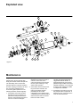
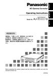
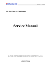
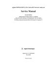
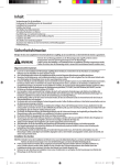
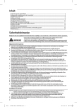
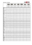
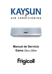
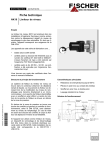
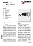
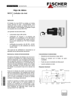
Vickers® Cylinders Series TE/TF/TL Air & Hydraulic Cylinders Installation & Service Manual Contents Introduction . . . . . . . . . . . . . . . . . . . . . . . . . . . . . . . . . . . . . . . . . . . . . . . . . . . . . . . . . . . . . . . . . . . . . . . . . . . . . . . . . . . . . . . . . . . . . . . . . . . . 1 Cylinder Installation . . . . . . . . . . . . . . . . . . . . . . . . . . . . . . . . . . . . . . . . . . . . . . . . . . . . . . . . . . . . . . . . . . . . . . . . . . . . . . . . . . . . . . . . . . . . . 2 Troubleshooting . . . . . . . . . . . . . . . . . . . . . . . . . . . . . . . . . . . . . . . . . . . . . . . . . . . . . . . . . . . . . . . . . . . . . . . . . . . . . . . . . . . . . . . . . . . . . . . . 3 Service . . . . . . . . . . . . . . . . . . . . . . . . . . . . . . . . . . . . . . . . . . . . . . . . . . . . . . . . . . . . . . . . . . . . . . . . . . . . . . . . . . . . . . . . . . . . . . . . . . . . . . . 5 Exploded View . . . . . . . . . . . . . . . . . . . . . . . . . . . . . . . . . . . . . . . . . . . . . . . . . . . . . . . . . . . . . . . . . . . . . . . . . . . . . . . . . . . . . . . . . . . . . . . . . 7 Maintenance . . . . . . . . . . . . . . . . . . . . . . . . . . . . . . . . . . . . . . . . . . . . . . . . . . . . . . . . . . . . . . . . . . . . . . . . . . . . . . . . . . . . . . . . . . . . . . . . . . . 7 Replacement Parts . . . . . . . . . . . . . . . . . . . . . . . . . . . . . . . . . . . . . . . . . . . . . . . . . . . . . . . . . . . . . . . . . . . . . . . . . . . . . . . . . . . . . . . . . . . . . 9 How to Order . . . . . . . . . . . . . . . . . . . . . . . . . . . . . . . . . . . . . . . . . . . . . . . . . . . . . . . . . . . . . . . . . . . . . . . . . . . . . . . . . . . . . . . . . . . . . . . . . 21 Model Code (Cylinder Identification) . . . . . . . . . . . . . . . . . . . . . . . . . . . . . . . . . . . . . . . . . . . . . . . . . . . . . . . . . . . . . . . . . . . . . . . . . . . . . . 22 Vickers, Incorporated 1997 All Rights Reserved Introduction Purpose of manual Custom cylinders Replacement parts This manual has been prepared to assist users of Vickers Series TE, TF and TL cylinders for properly maintaining and repairing their units. In the sections that follow, instructions are given for proper installation, maintenance and overhaul. Although the model code has been arranged to cover the vast majority of available options, there will be occasions when an option which cannot be coded will be required. When such an option has been specified, enter an “X” for the appropriate item in the model code. For example, an application which requires a custom thread on the end of the piston rod, an “X” is inserted for item 7. The cylinder will include a unique five digit design number. Each design number has a completed bill of materials on file in a quick retrieval computerized storage system. This gives the Field Sales Representatives rapid access in identifying and specifying genuine Vickers replacements parts. General information Model codes have many variations within a basic model series. They are covered by variables in the model code. Service inquiries should always include the complete model code number as stamped on the head or cap and three digit plant code. How to order Vickers has developed an easy system for ordering cylinders. This system has been developed to improve ease of ordering. The model code consists of sixteen alpha-numeric digits which fully describe the most common standard options offered. To specify your cylinder, review the Model Code section for a full description of each option available and corresponding code. Replacement cylinders Every custom cylinder is assigned a unique design number. This number is contained in the last five digits of the sixteen digit model code. Item 12 is always an alpha character. The “Stroke” and “Extra Rod Projection” positions (items 12 through 16) become the “Design Number” items for custom cylinders. When ordering a replacement part or cylinder, give the sixteen digit model code or the five digit design number to your local Vickers Representative. Figure 1. Cylinder Section View 1 Cylinder Installation All Vickers Series TE, TF and TL cylinders are individually tested and inspected before shipment to assure freedom from defects. Plugs are inserted in the ports to protect threads and keep foreign matter from entering the cylinder prior to installation. Mounting and alignment Position the cylinder loosely in the mounting and check the alignment of the piston rod with the load connection at both ends of the stroke. If the cylinder is too large to move by hand, proceed with piping and installation and operate cylinder throughout the stroke prior to connection. Trunnion and swivel mount bearings should fit closely for the entire length of the pin, and must be square with the load connection throughout the stroke. Flush or foot mounted cylinders may be pinned or keyed to prevent shifting during high shock loads. Always use the wrench flats when connecting piston rod to load to prevent damage to the sealing surface. Tighten piston rod against shoulder or use a locknut on full size threads. If cylinder has been pressurized, relieve all pressure prior to turning the piston rod. Piping connections All piping connections should be deburred and the system thoroughly flushed to purge all contaminants prior to connecting cylinder ports. Care should be taken to prevent over tightening of the piping connections. Cylinder operation Cycle cylinder a few times with reduced load and pressure. Hydraulic cylinders may be erratic due to trapped air, but will normally purge themselves after several cycles. Some cylinders may be equipped with air bleed screws which can be slowly loosened with a male key wrench, then re-tightened after air is purged. Cushioned cylinders are adjusted and tested prior to shipping, but usually require additional adjustment after connection to the work load. If cushion adjustment screw has a locknut, loosen and hold with wrench while turning the screw. To increase effectiveness of the cushion, turn the adjustment screw clockwise. To provide less cushion, turn the screw counterclockwise. Most orifices are fully open with two full turns of the screw from the closed position. The final position of the screw should be a balance between any shock or bounce at the start of the cushion and the final impact of the piston at the end of stroke. 2 Troubleshooting Most problems in fluid power circuits result in a gradual or sudden loss of power in the work cylinders, which may cause them to stall or move slower than required. This chart assumes that all other components of the circuit such as the pump, relief valve, control valves, hydraulic supply, etc. have been checked and the problem has been isolated to the cylinder. Properly installed and maintained cylinders should function for millions of cycles. Premature cylinder failures are usually caused by system or application problems that can be prevented. The purpose of this chart is to aid in identifying and correcting the most common causes of premature cylinder failure. Check Cylinder for Evidence of: Caused By: Action Required: Excessive wear on piston rod. Side load due to misalignment between cylinder and load. Check alignment of rod with load connection at all points in stroke. Pivot mount cylinder without proper stop tubing. Follow Vickers cylinder catalog design recommendations. Exceptionally dirty environment. Clean and flush the entire system, deburr connections. Worn rod wiper/scraper Shield piston rod area from direct contact with contaminant. Lack of, or improperly adjusted cushions. Reference adjustment instructions in this manual. Load and piston speed combination exceeds cylinder cushion capacity. Consult your Vickers Sales Engineer. Lack of, or improperly adjusted speed controls. Add or adjust flow controls to reduce piston speed. Excessive system pressure. Reduce pressure to minimum required to move the load. Contamination in cylinder. y Impact damage g or b k parts. broken t Permanent deformation System pressure in excess of cylinder rating. or damaged g static seals. l High pressure developed in cylinder cushion. Cyl. externally loaded while control valve is closed. Excessive temperature in environment or Seal damage such as loss of elasticity, y, shape,, system. etc. t Incompatible hydraulic fluid. Cylinder stored in horizontal position for extended period. Follow Vickers cylinder catalog design recommendations. Consult your Vickers Sales Engineer. Reduce load magnitude or re-size cylinder. Install replacement sealing system with proper rating. Refer to Vickers cylinder catalog or page 6 of this manual for compatible sealing system. Replace seals, store vertically with rod up. Table 1. Additional Troubleshooting Information The following information is intended to supplement the above troubleshooting table. Additional details help with the identification and resolution of frequent cylinder application problems. Steps are provided for correcting each suspected application problem. 1. Excessive Side Load on Piston Rod Excessive side loads imposed by improper alignment or other causes are a common misapplication of cylinders. Cylinders may bind, stick, or move erratically if the operating pressure is low. Higher operating pressures will force the cylinder to move, but eventually cause premature bearing wear, rod leakage, or extensive cylinder damage. High side loads are frequently caused by improper alignment. A. Disconnect the piston rod end from the machine. Observe the alignment of the rod end at each end of the stroke and in midstroke. B. Adjust the cylinder mounting, if possible, or add a self aligning coupler on rigid mount cylinders. C. Additional clearances can sometimes be added to clevis mount cylinders to allow some lateral movement during the stroke. D. Spherical alignment bushings (SAB mounts) can be used to allow for some mounting misalignment. 3 Troubleshooting 2. External Leakage (hydraulic) Isolate the source of any visible external leakage to make sure it is coming from the cylinder, then find the exact location of the leakage. External leakage is generally confined to port connections, rod seals, body seals, and cushion adjustment screws. A. Port Connection: 1. Tighten NPTF ports or re-seal with thread sealing material. 2. Inspect SAE o-ring ports for damaged sealing surfaces or o-ring seals. B. Rod Seals: 1. Inspect for physical seal damage such as linear scratches, torn sealing edges, etc. If found, determine the cause of the damage (i.e. wrench marks etc.). Correct the source of the problem before installing new seals. 2. If the seals look good, check fluid compatibility and operating temperatures. 3. Pressure energized lip seals may exhibit some light leakage when circuit pressures, even momentarily, turn negative (instantaneous vacuum). This can occur on very fast operating cylinders with the exhausting fluid, in some servo circuits, and when there is an overrunning load (the load pushing the cylinder). This problem may be corrected with the “wave washer” type of pre-load on the standard v-ring rod seals or by using another type of pre-loaded seal. 3. If the tie rod torque is to proper specification, the most likely cause of any body seal leakage is excessive pressure within the cylinder. In addition to the working system pressure, look for hydraulic cushion shocks or high external load applied back to the cylinder when the control valve is closed. 4. Determine which circuit components may be the source of shock pressure. For example, certain types of air-to-oil boosters impart high peak shocks due to sudden action of the booster. D. Cushion Adjustment Screws: 1. Inspect o-ring seals for physical damage or other types of seal deterioration due to problems with fluid compatibility, heat, etc. 3. Internal Leakage (hydraulic) A. Verify the type of piston seal found in the cylinder. Cast iron rings will always pass a small amount of fluid. B. Check the internal leakage by first blocking the cylinder piston in mid-stroke, then pressurizing one side of the piston. If a rod clevis is available, the same check can be done by reversing the clevis on the rod, then letting the clevis ears come up against the rod end head while pressurizing the rod end of the cylinder. C. Leaking piston seals usually result from damage caused by internal contaminants or scratched surfaces on the piston seal groove or body inside diameter. 1. Check the tie rod torque value. Make sure it is even around all the rods. D. Certain types of seals may take a compression set if the cylinder is stored in a horizontal position for a long time before being installed and operated. 2. O-rings should be replaced if there are any signs of seal damage. 4. Insufficient Cushion Action (hydraulic) C. Body Seals: A. Adjust the cushion screws to minimize the “bump” at the start of the cushion and at the end of the stroke. 4 B. Floating metallic cushions should be able to shut off the motion of the cylinder about 3/4” from the end of the stroke. Do not attempt to shut the screws all the way off unless you can operate the cylinder very slowly. C. Occasionally, even though the cushion is sealing properly, the desired cushioning cannot be obtained by adjusting the cushion screws. In such applications, the combined load and velocity may require a custom design to achieve the proper performance. D. Sometimes a reduction in working pressure will significantly improve cushion performance without adversely affecting the overall performance of the cylinder. 5. Insufficient Cushion Action (pneumatic) A. Operate the pneumatic cylinder to check operation of the air cushion with the screw fully closed. The cylinder should stop short of its full stroke. B. Due to the compressibility of air, pneumatic cushions are much more sensitive to adjustments than hydraulic cushions. First try adjusting the cushion screws to eliminate “bounce” at the beginning of the cushion, and to prevent high impact at the end of the stroke. C. If the piston “punches through” the cushion with high impact at the head -- not enough air is being trapped. A speed control in the exhaust air line can often raise the back pressure enough to improve the cushion action, while not significantly slowing the speed of the stroke. Lowering the system air pressure slows the speed of the stroke and may also have a dramatic effect on the cushioning action. D. If cushion “bounces” or has too much air spring, turn the screws wide open, increase air pressure and try to minimize back pressure in the exhaust line. Service The following instructions describe the complete rebuilding of your Vickers TE, TF or TL cylinder. Refer to Figure 4 exploded view. Warning Before breaking a circuit connection, make certain that power is off and system pressure has been released. Lower all vertical cylinders, discharge accumulators, and block any load whose movement could generate pressure. Plug all removed units and cap all lines to prevent the entry of dirt into the system. Required Tools Spanner wrench Adjustable wrench Soft brass tool Thin tool (like a metal ruler) Copper padded vice Rubber mallet Torque wrench Replacing Rod Seals 1. Once the cylinder is removed from service, fully retract the piston rod and remove all port connections. Drain any hydraulic fluid by manually cycling the cylinder. Large cylinders can be carefully cycled with air pressure. 2. The Quick Change rod cartridge allows rod seal replacement without disturbing the tie rods. Remove any burrs from the wrench flat area of the piston rod. Place the cylinder in a vice, rod end up if possible. Remove the rod bearing retainer plate by removing the retainer screws. The retainer may be round, square or rectangular. Round retainers that are recessed into the head have a pry groove on the O.D. or two tapped holes to aid removal. 3. Remove the rod seals on smaller cylinders by placing your thumb over the rod end port and giving a quick pull on the piston rod. Use low pressure air in the rod end port for larger cylinders. Leave the bearing on the rod to catch the seals as they leave the seal cavity. Note the position of the male seal adaptor relative to the bearing and the seals. Leave the male seal adapter in place if in the bottom of the seal cavity, to support the piston rod while performing the remaining disassembly. 4. Remove the elastomer rod wiper or rod scraper retainer from the rod bearing. Remove the rod scrapers if applicable. 5. For metallic scrapers, stack the new scraper rings so that the slots are staggered. Lightly lubricate the new wiper or retainer and push it into the bearing groove with a soft brass tool. 6. Lightly lubricate the new rod seals and replace, one at a time, by leading the outside sealing edge with a soft brass tool as each seal is inserted in the cavity. Be careful not to damage the seals when placing them over the piston rod. 7. Carefully replace the bearing on the rod. Slide the retainer plate into position. Replace the retainer screws, and tighten in a cross sequence pattern. Torque to values shown in Table 2 below. Retainer Screw Torque 4. The piston does not have to be removed from the rod for normal piston seal replacement. Cast iron piston rings may be removed by inserting a thin tool under the joint and running it around the circumference of the piston. 5. Remove the nonmetallic wear band which simply snaps into the groove on the piston’s outer diameter, if applicable. 6. If piston removal from the rod is required, slide the piston rod assembly out of the cylinder body. Clamp the rod securely in a copper padded vice that will protect the rod finish. If a locknut holds the piston to the rod, loosen and remove locknut. 7. If no locknut is present, heat the piston to approximately 350_ F with a torch or in an oven to break the anaerobic adhesive. Insert a spanner wrench in the drilled holes on the piston face and break the seal by rapping the wrench with a rubber mallet, rotating the piston in a counterclockwise direction. CAUTION THE PISTON IS HOT! Retainer Screw Size 1/ - 28 4 5/ - 24 16 3/ - 24 8 1/ - 20 2 Screw Part # 6893 -1 -2 -1, -3 -4 -3, -5 -6, -7 Screw Rec. Part # Torque 6894 (ft-lbs) -1 -2 -1, -2, -3 7 -4 -5 -4, 12 -6 -7 -6, 22 -8, -9 50 Table 2. Complete Rebuild 1. Repeat steps 1, 2, 3, 4 and 5 in Replacing rod seals section. 2. Remove the tie rod nuts, loosening in a cross sequence pattern. Carefully remove the cap or head from the tie rods and inspect for damage or signs of contamination. 3. Remove the cylinder body from the head/cap. Slide the piston rod assembly out of the cylinder body. It is not necessary to remove the tie rods if threaded into a tapped head or cap for servicing, unless the tapped head or cap is mechanically damaged. 8. Unscrew the piston and set it aside. 9. Remove the cushion collar from the rod, if the cylinder is cushioned on the head end. Let the rod cool before re-assembly. 10. Snugly secure the rod into the vice. Replace the cushion collar on the rod (if required). Thoroughly clean all metallic surfaces with a non-petroleum based cleaner and a wire brush, if necessary. 11. Apply anaerobic adhesive near the rod shoulder (or collar) on the rod threads and on the piston I.D. threads. NOTE Be sure to follow the adhesive manufacturer’s recommendations regarding surface preparation, priming requirements, proper adhesive for the thread size, and cure time prior to pressurization. Failure to do so could result in improper sealing and retention. 5 12. If piston is theaded, screw the piston onto the rod, hand tight. Insert the spanner wrench and tighten by lightly rapping it with a mallet. Otherwise slide the piston on the rod and screw the locknut on the rod and tighten. 13. Place the piston rings at an angle over the piston and slip them into the grooves. For elastomeric type seals, place the flexible seal into the top groove. Flip the piston over and repeat the process with the remaining seal. 14. New cup seals are installed by placing one side in the piston groove and stretching the seal around the circumference with the thin tool used in disassembly. Make sure that the lips of the seals face the outside of the piston. Bore ∅ (in.) Tie Rod ∅ (in.) 11/2 1/ - 28 4 5/ - 24 16 3/ - 24 8 1/ - 20 2 5/ - 18 8 3/ - 16 4 2, 21/2 31/4, 4 5, 6, 7, 8 10, 12 14 Note the sleeve orientation in the groove before removal. Some sleeves are not symmetrical and new sleeves must be installed in the groove in the same orientation. 17. Shorter cylinders are more easily assembled in a vertical position. Insert the body o-ring in the cap body groove and position the cylinder body on the cap. 18. Place a ring compressor sleeve tool on the body. Lube the piston O.D. and the rings. Carefully insert the piston into the cylinder body. 20. Repeat steps 6 and 7 in “Replacing rod seals” section. 21. Start the tie rod nuts until snug against the head or cap and lay the cylinder on its side. Secure the cylinder horizontally into a vice or clamped to a flat surface. 22. Tighten the tie rod nuts gradually in a cross sequence pattern to equally distribute forces around the cylinder with a torque wrench. The required torque values are listed in Table 3. Check each nut a second time after reaching full torque. 19. Install the body o-ring in the head body groove. When properly installed, the o-ring should remain in the head when inverted. Grease will hold the o-ring in place if required. Place the cylinder head with tie rods on the body. Rec. Torque* (ft. lb.) 8 Table 4. Seal Compatibility with Common Fluids 16 Standard seal material is Nitrile and is compatible with most applications. Optional seal compounds are VitonR and EPR. The fluid compatibility of these standard and optional seal compounds is listed below: 28 66 130 225 Table 3. * Recommended torque values using MoS2 lubricant with 0.12 coefficient of friction. 15. Cylinder body o-rings are easily removed using a thin blade tool. Care should be taken to avoid damaging the surface finish in the groove with the tool. 16. Metallic cushion sleeves can be replaced by removing the snap ring sleeve retainers. Class of Hydraulic Fluid Nitrile (std) EPR (opt) Petroleum base Phosphate ester Compatible Not compatible Not compatible Compatible Compatible Compatible Silicone Water Water/Oil Emulsion Water-Glycol Ethylene Glycol Auto Trans. Fluid Auto Brake Fluid Compatible Compatible Compatible Compatible Compatible Compatible Not compatible -40_ F to +250_ F Compatible Compatible Not compatible Compatible Compatible Not compatible Compatible -65_ F to +300_ F Temperature Ranges 1 Standard & Optional Seal Compounds R E.I. du Pont trade name for fluroelastomer (FPM). 1 Maximum ratings for continuous exposure. 6 Viton (opt) Compatible Compatible Compatible Compatible Compatible Compatible Not compatible -20_ F to +400_ F Exploded view 9 10 8 11 1 21 20 13 19 23 24 18 22 7 12 6 4 3 2 12 25 16 15 5 26 17 15 14 Figure 4. Maintenance Inspection All parts in the unit must be kept clean during the overhaul. Handle each part with care and always work in a clean area. Periodic inspection of the fluid condition and tube or piping connections can save time consuming breakdowns and unnecessary parts replacement. The following should be checked regularly: 1. All hydraulic connections must be kept tight. A loose connection in a pressure line will permit the fluid to leak out. If the fluid level becomes so low as to uncover the inlet pipe opening in the reservoir, extensive damage to the pump can result. In suction or return lines, loose connections permit air to be drawn into the system resulting in noisy and/or erratic operation. 2. Clean fluid is the best insurance for long service life. Therefore, the reservoir should be checked periodically for dirt or other contaminants. If the fluid becomes contaminated, the system should be drained and the reservoir cleaned before new fluid is added. 3. Filter elements also should be checked and replaced periodically. A clogged filter element results in a higher pressure drop. This can force particles through the filter which would ordinarily be trapped, or can cause the by-pass to open, resulting in a partial or complete loss of filtration. 4. Air bubbles in the reservoir can ruin the pump and other components. If bubbles are seen, locate the source of the air and seal the leak. 7 Cleanliness Thorough precautions should always be observed to insure the hydraulic system is clean: 1. Clean (flush) entire new system to remove paint, metal chips, welding shot, etc. 2. Filter each change of oil to prevent introduction of contaminants into the system. 3. Provide continuous oil filtration to remove sludge and products of wear and corrosion generated during the life of the system. 4. Provide continuous protection of system from entry of airborne contamination by sealing the system and/or by proper filtration of the air. 5. During usage, proper oil filling and servicing of filter, breathers, reservoirs, etc., cannot be over emphasized. 6. Thorough precautions should be taken by proper system and reservoir design, to insure that aeration of the oil will be kept to a minimum. Vickers supports and recommends the hydraulic Systems Standards for Stationary Industrial Machinery advanced by the American National Standards Institute; ANSI/(NFPA/JIC) T2.24.1–1991. Key elements of this Standard as well as other vital information on the correct methods for treating hydraulic fluid are included in Vickers publication #561; “Vickers Guide to Systemic Contamination Control,” available from your local Vickers distributor or by contacting Vickers. Recommendations on filtration and the selection of products to control fluid condition are included in this publication. Sound Level Noise is only indirectly affected by the fluid selection, but the condition of the fluid is of paramount importance in obtaining optimum reduction of system sound levels. Some of the major factors affecting the fluid conditions that cause the loudest noises in a hydraulic system are: 8 1. Very high viscosities at start–up temperature can cause pump noises due to cavitation. 2. Running with a moderately high viscosity fluid will slow the release of air captured in the fluid. The fluid will not be completely purged of such air in the time it remains in the reservoir before recycling through the system. 3. Aerated fluid can be caused by ingestion of air through the pipe joints of inlet lines, high velocity discharge lines, cylinder rod packings or by fluid discharging above the fluid level in the reservoir. Air in the fluid causes a noise similar to cavitation. Hydraulic Fluid Recommendations Oil in a hydraulic system performs the dual function of lubrication and transmission of power. It constitutes a vital factor in a hydraulic system, and careful selection of it should be made with the assistance of a reputable supplier. Proper selection of oil assures satisfactory life and operation of system components with particular emphasis on hydraulic pumps. Any oil selected for use with pumps is acceptable for use with valves, cylinders or motors. Order literature #694 for oil selection recommendations. Adding Fluid to the System When hydraulic fluid is added to the system, it should be pumped through a 10 micron absolute filter. The use of a Vickers Clean Cart portable filtering transfer unit to filter clean fluid into the system is recommended. For further information on the Clean Cart transfer unit, obtain service drawing #601. It is important that the fluid be kept clean and free from any substance that may cause improper operation or wear to the cylinder, pump and other hydraulic units. Therefore, the use of cloth to strain the fluid should be avoided to prevent lint from entering the system. Replacement Parts Reliable operation throughout the specified operating range is assured only if genuine Vickers parts are used. Sophisticated design processes and materials are used in the manufacture of our parts. Substitutes may result in early failure. Product Life The service life of these products is dependent on environment, duty cycle, operating parameters and system cleanliness. Since these parameters vary from application to application, the ultimate user must determine and establish the periodic maintenance required to maximize life and detect potential component problems. Fluids Proper fluid condition is essential for long and satisfactory life of hydraulic components and systems. Hydraulic fluid must have the correct balance of cleanliness, materials and additives for protection against wear of components, elevated viscosity and inclusion of air. Essential information on the correct methods for treating hydraulic fluid is included in Vickers publication 561; “Vickers Guide to Systemic Contamination control,” available from your local Vickers distributor or by contacting Vickers, Incorporated. Recommendation of filtration and the selection of products to control fluid condition are included in #561. Recommended cleanliness levels using petroleum oil under common conditions is based on the highest fluid pressure levels in the system. Fluids other than petroleum, severe service cycles or temperature extremes are cause for adjustment of these cleanliness codes. See Vickers Publication 561 for exact details. System Pressure Level Product 1000 psi Cylinders 20/18/15 2000 psi 3000+ psi 20/18/15 20/18/15 Replacement Parts - Single Rod Cylinders Refer fold out page 20 – Figure 5 Key No No. Part Name No Req’d BORE SIZE 5/ ” 8 ROD 1 1/2” BORE SIZE 2” 1” ROD 5/ ” 8 1 ROD ROD 1 Piston rod Non–cushioned (# = rod end type) Cushioned head end Cushioned cap end Specify stroke Cushioned both ends 1 1 1 1 TE82C#DA10A_ _ _ _ TE82C#DF10A_ _ _ _ TE82C#DB10A_ _ _ _ TE82C#DK10A_ _ _ _ TE82E#CA10A_ _ _ _ TE82E#CF10A_ _ _ _ TE82E#CB10A_ _ _ _ TE82E#CK10A_ _ _ _ TE82C#DA10A_ _ _ _ TE82C#DF10A_ _ _ _ TE82C#DB10A_ _ _ _ TE82C#DK10A_ _ _ _ TE82E#DA10A_ _ _ _ TE82E#DF10A_ _ _ _ TE82E#DB10A_ _ _ _ TE82E#DK10A_ _ _ _ 2 Rod wiper (air) Rod scraper (hydraulic) 1 1 5026-5/8 5030-5/8 5026-1 5030-1 5026-5/8 5030-5/8 5026-1 5030-1 3 Rod bearing 1 TX81C1020 TX81E1040 TX81C1000 TX81E1040 4 Rod seal 3 5070-14 5070-20 5070-14 5070-20 5 Seal adaptor 1 SM-77-2-B SM-77-4-B SM-77-2-B SM-77-4-B 6 Cushion seal (head end) – for head end cushioned air cylinders only 1 5050-11 N/A 5050-2 N/A 7 Body (specify stroke) 1 TE57CA_ _ _ TE57CA_ _ _ TE57DA_ _ _ TE57DA_ _ _ 8 Cushion collar 1 TE93C1 TE93EC1 TE93CD1 TE93ED1 9 Piston seal (U-cup design only) 2 5120-15 5120-15 5120-20 5120-20 10 Piston 1 TE53CU0C0 TE53CU0E0 TE53DU0B0 TE53DU0E0 11 Piston locknut 1 364 N/A 364 N/A 12 Body o-ring 2 5145-029-A 5145-029-A 5145-033-A 5145-033-A 13 Cushion seal (cap end) – for cap end cushioned air cylinders only 1 5050-10 5050-10 5050-10 5050-10 14 Cushion adjusting screw (2 req’d if cushioned both ends) 0-2 SM-95-1-B SM-95-1-B SM-95-1-B SM-95-1-B 15 Cushion adjusting screw o-ring (2 req’d if cushioned both ends) 0-2 5145-006-A 5145-006-A 5145-006-A 5145-006-A 16 Cushion adjusting screw locknut (2 req’d if cushioned both ends) 0-2 SM-96-1-B SM-96-1-B SM-96-1-B SM-96-1-B 17 Cushion adjusting screw locknut o-ring (2 req’d if cushioned both ends) 0-2 5145-010 5145-010 5145-010 5145-010 18 Cushion sleeve (head end) – for head end cushioned hydraulic cylinders only 1 S-92-3-1-B N/A S-92-4-1-B LSM-294-AL 19 Sleeve retainer ring (head end) – for head end cushioned hydraulic cylinders only 1 S-92-3-2 N/A S-92-4-2 N/A 20 Cushion sleeve (cap end) – for cap end cushioned hydraulic cylinders only 1 S-92-1-1-B S-92-1-1-B S-92-1-1-B S-92-1-1-B 21 Sleeve retainer ring (cap end – for cap end cushioned hydraulic cylinders only 1 S-92-1-2 S-92-1-2 S-92-1-2 S-92-1-2 22 Steel ball 1 N/A N/A N/A 5205-002 23 Ball retainer screw 1 N/A N/A N/A 5255-1/16 24 Ball retainer screw o-ring 1 N/A N/A N/A N/A 25 Tie rods (specify mounting style/bore/stroke) as req’d consult factory 26 Tie rod nuts (specify mounting style/bore) as req’d consult factory 9 Replacement Parts - Single Rod Cylinders Refer fold out page 20 – Figure 5 Key No No. 10 No Req’d BORE SIZE 2” 1 1 1 1 1 TE82H#DA10A_ _ _ _ TE82H#DF10A_ _ _ _ TE82H#DB10A_ _ _ _ TE82H#DK10A_ _ _ _ 2 1 3 4 BORE SIZE 2 1/2” 1 ROD 1 3/8” ROD 1 3/4” ROD TE82C#EA10A_ _ _ _ TE82C#EF10A_ _ _ _ TE82C#EB10A_ _ _ _ TE82C#EK10A_ _ _ _ TE82E#EA10A_ _ _ _ TE82E#EF10A_ _ _ _ TE82E#EB10A_ _ _ _ TE82E#EK10A_ _ _ _ TE82H#EA10A_ _ _ _ TE82H#EF10A_ _ _ _ TE82H#EB10A_ _ _ _ TE82H#EK10A_ _ _ _ TE82L#EA10A_ _ _ _ TE82L#EF10A_ _ _ _ TE82L#EB10A_ _ _ _ TE82L#EK10A_ _ _ _ 5026-13/8 5030-13/8 5026-5/8 5030-5/8 5026-1 5030-1 5026-13/8 5030-13/8 5026-13/4 5030-13/4 1 TE81H1120 TX81C1000 TX81E1040 TE81H1120 TX81L1180 3 5070-26-1 5070-14 5070-20 5070-26-1 5070-29-1 5 1 SM-77-6-1-B SM-77-2-B SM-77-4-B SM-77-6-1-B SM-77-8-1-B 6 1 N/A 5050-2 Use items 18 & 19 N/A N/A 7 1 TE57DA_ _ _ TE57EA_ _ _ TE57EA_ _ _ TE57EA_ _ _ TE57EA_ _ _ 8 1 TE93HD1 TE93CD1 TE93EE1 TE93HD1 TE93LE1 9 2 5120-20 5120-25 5120-25 5120-25 5120-25 10 1 TE53DU0H0 TE53EU0C0 TE53EU0E0 TE53EU0H0 TE53EU0L0 1 3/ ” 8 ROD 5/ ” 8 ROD 11 1 N/A 364 N/A N/A N/A 12 2 5145-033-A 5145-037-A 5145-037-A 5145-037-A 5145-037-A 13 1 5050-10 5050-10 5050-10 5050-10 5050-10 14 0-2 SM-95-1-B SH-95-15 SH-95-15 SH-95-15 SH-95-15 15 0-2 5145-006-A 5145-006-A 5145-006-A 5145-006-A 5145-006-A 16 0-2 SM-96-1-B N/A N/A N/A N/A 17 0-2 5145-010 N/A N/A N/A N/A 18 1 N/A S-92-4-1-B S-92-7-1-B N/A N/A 19 1 N/A S-92-4-2 S-92-7-2-A N/A N/A 20 1 S-92-1-1-B S-92-1-1-B S-92-1-1-B S-92-1-1-B S-92-1-1-B 21 1 S-92-1-2 S-92-1-2 S-92-1-2 S-92-1-2 S-92-1-2 22 1 5205-002 N/A N/A 5205-003 5205-002 23 1 5255-1/16 N/A N/A SH-98-15 5255-1/16 24 1 N/A N/A N/A 5145-006-A N/A 25 as req’d consult factory 26 as req’d consult factory Replacement Parts - Single Rod Cylinders Refer fold out page 20 – Figure 5 Key No No. Part Name No Req’d BORE SIZE 3 1/4” 1” ROD 13/8” ROD 13/4” ROD 2” ROD 1 Piston rod Non–cushioned (# = rod end type) Cushioned head end Cushioned cap end Specify stroke Cushioned both ends 1 1 1 1 TE82E#HA10A_ _ _ _ TE82E#HF10A_ _ _ _ TE82E#HB10A_ _ _ _ TE82E#HK10A_ _ _ _ TE82H#HA10A_ _ _ _ TE82H#HF10A_ _ _ _ TE82H#HB10A_ _ _ _ TE82H#HK10A_ _ _ _ TE82L#HA10A_ _ _ _ TE82L#HF10A_ _ _ _ TE82L#HB10A_ _ _ _ TE82L#HK10A_ _ _ _ TE82M#HA10A_ _ _ _ TE82M#HF10A_ _ _ _ TE82M#HB10A_ _ _ _ TE82M#HK10A_ _ _ _ 2 Rod wiper (air) Rod scraper (hydraulic) 1 1 5026-1 5030-1 5026-13/8 5030-13/8 5026-13/4 5030-13/4 5026-2 5030-2 3 Rod bearing 1 TX81E1040 TE81H1100 TE81L1580 TE81M1220 4 Rod seal 3 5070-20 5070-26 5070-29 5070-31 5 Seal adaptor 1 SM-77-4-B SM-77-6-B SM-77-8-B SM-77-9-B 6 Cushion seal (head end) – for head end cushioned air cylinders only 1 5050-3 N/A N/A N/A 7 Body (specify stroke) 1 TE57GA_ _ _ TE57GA_ _ _ TE57GA_ _ _ TE57GA_ _ _ 8 Cushion collar 1 TE93EH1 TE93HH1 TE93LH1 TE93MH1 9 Piston seal (U-cup design only) 2 5120-32 5120-32 5120-32 5120-32 10 Piston 1 TE53GU0E0 TE53GU0H0 TE53GU0L0 TE53GU0M0 11 Piston locknut 1 664 N/A 364 N/A 12 Body o-ring 2 5145-042-A 5145-042-A 5145-042-A 5145-042-A 13 Cushion seal (cap end) – for cap end cushioned air cylinders only 1 5050-1 5050-1 5050-1 5050-1 14 Cushion adjusting screw (2 req’d if cushioned both ends) 0-2 SH-95-15 SH-95-15 SH-95-15 SH-95-15 15 Cushion adjusting screw o-ring (2 req’d if cushioned both ends) 0-2 5145-006-A 5145-006-A 5145-006-A 5145-006-A 16 Cushion adjusting screw locknut (2 req’d if cushioned both ends) 0-2 N/A N/A N/A N/A 17 Cushion adjusting screw locknut o-ring (2 req’d if cushioned both ends) 0-2 N/A N/A N/A N/A 18 Cushion sleeve (head end) – for head end cushioned hydraulic cylinders only 1 LSM-92-5-B N/A N/A N/A 19 Sleeve retainer ring (head end) – for head end cushioned hydraulic cylinders only 1 LSM-92-5-2 N/A N/A N/A 20 Cushion sleeve (cap end) – for cap end cushioned hydraulic cylinders only 1 S-92-2-1-B S-92-2-1-B S-92-2-1-B S-92-2-1-B 21 Sleeve retainer ring (cap end – for cap end cushioned hydraulic cylinders only 1 S-92-2-2 S-92-2-2 S-92-2-2 S-92-2-2 22 Steel ball 1 N/A 5205-003 5205-003 5205-003 23 Ball retainer screw 1 N/A SH-98-15 SH-98-15 SH-98-15 24 Ball retainer screw o-ring 1 N/A 5145-006-A 5145-006-A 5145-006-A 25 Tie rods (specify mounting style/bore/stroke) as req’d consult factory 26 Tie rod nuts (specify mounting style/bore) as req’d consult factory 11 Replacement Parts - Single Rod Cylinders Refer fold out page 20 – Figure 5 Key No No. 12 No Req’d BORE SIZE 4” 1” ROD 1 3/ ” 8 ROD 1 3/ ” 4 ROD 2” ROD 2 1/2” ROD 1 1 1 1 1 TE82E#HA10A_ _ _ _ TE82E#HF10A_ _ _ _ TE82E#HB10A_ _ _ _ TE82E#HK10A_ _ _ _ TE82H#HA10A_ _ _ _ TE82H#HF10A_ _ _ _ TE82H#HB10A_ _ _ _ TE82H#HK10A_ _ _ _ TE82L#HA10A_ _ _ _ TE82L#HF10A_ _ _ _ TE82L#HB10A_ _ _ _ TE82L#HK10A_ _ _ _ TE82M#HA10A_ _ _ _ TE82M#HF10A_ _ _ _ TE82M#HB10A_ _ _ _ TE82M#HK10A_ _ _ _ TE82P#HA10A_ _ _ _ TE82P#HF10A_ _ _ _ TE82P#HB10A_ _ _ _ TE82P#HK10A_ _ _ _ 2 1 5026-1 5030-1 5026-1-3/8 5030-1-3/8 5026-1-3/4 5030-1-3/4 5026-2 5030-2 5026-2-1/2 5030-2-1/2 3 1 TX81E1040 TE81H1100 TE81L1580 TE81M1220 TE81P1280 4 3 5070-20 5070-26 5070-29 5070-31 5070-35 5 1 SM-77-4-B SM-77-6-B SM-77-8-B SM-77-9-B SM-77-11-B 6 1 5050-3 N/A N/A N/A N/A 7 1 TE57HA_ _ _ TE57HA_ _ _ TE57HA_ _ _ TE57HA_ _ _ TE57HA_ _ _ 8 1 TE93EH1 TE93HH1 TE93LH1 TE93MH1 TE93PH1 9 2 5120-40 5120-40 5120-440 5120-40 5120-40 10 1 TE53HU0E0 TE53HU0H0 TE53HU0L0 TE53HU0M0 TE53HU0P0 11 1 N/A 364 N/A N/A N/A 12 2 5145-045-A 5145-045-A 5145-045-A 5145-045-A 5145-045-A 13 1 5050-1 5050-1 5050-1 5050-1 5050-1 14 0-2 SH-95-32 SH-95-32 SH-95-32 SH-95-32 SH-95-32 15 0-2 5145-008-A 5145-008-A 5145-008-A 5145-008-A 5145-008-A 16 0-2 N/A N/A N/A N/A N/A 17 0-2 N/A N/A N/A N/A N/A 18 1 LSM-92-5-1-B N/A N/A N/A N/A 19 1 LSM-92-5-2 N/A N/A N/A N/A 20 1 S-92-2-1-B S-92-2-1-B S-92-2-1-B S-92-2-1-B S-92-2-1-B 21 1 S-92-2-2 S-92-2-2 S-92-2-2 S-92-2-2 S-92-2-2 22 1 N/A 5205-004 5205-004 5205-004 5205-004 23 1 N/A SH-98-32 SH-98-32 SH-98-32 SH-98-32 24 1 N/A 5145-008-A 5145-008-A 5145-008-A 5145-008-A 25 as req’d consult factory 26 as req’d consult factory Replacement Parts - Single Rod Cylinders Refer fold out page 20 – Figure 5 Key No No. Part Name No Req’d BORE SIZE 5” 1” ROD 13/8” ROD 13/4” ROD 2” ROD 1 Piston rod Non–cushioned (# = rod end type) Cushioned head end Cushioned cap end Specify stroke Cushioned both ends 1 1 1 1 TE82E#KA10A_ _ _ _ TE82E#KF10A_ _ _ _ TE82E#KB10A_ _ _ _ TE82E#KK10A_ _ _ _ TE82H#KA10A_ _ _ _ TE82H#KF10A_ _ _ _ TE82H#KB10A_ _ _ _ TE82H#KK10A_ _ _ _ TE82L#KA10A_ _ _ _ TE82L#KF10A_ _ _ _ TE82L#KB10A_ _ _ _ TE82L#KK10A_ _ _ _ TE82M#KA10A_ _ _ _ TE82M#KF10A_ _ _ _ TE82M#KB10A_ _ _ _ TE82M#KK10A_ _ _ _ 2 Rod wiper (air) Rod scraper (hydraulic) 1 1 5026-1 5030-1 5026-13/8 5030-13/8 5026-13/4 5030-13/4 5026-2 5030-2 3 Rod bearing 1 TX81E1040 TE81H1100 TE81L1580 TE81M1220 4 Rod seal 3 5070-20 5070-26 5070-29 5070-31 5 Seal adaptor 1 SM-77-4-B SM-77-6-B SM-77-8-B SM-77-9-B 6 Cushion seal (head end) – for head end cushioned air cylinders only 1 5050-3 N/A N/A N/A 7 Body (specify stroke) 1 TE57KA _ _ _ TE57KA_ _ _ TE57KA_ _ _ TE57KA_ _ _ 8 Cushion collar 1 TE93EH1 TE93HH1 TE93LH1 TE93MH1 9 Piston seal (U-cup design only) 2 5120-50 5120-50 5120-50 5120-50 10 Piston 1 TE53KU0E0 TE53KU0H0 TE53KU0L0 TE53KU0M0 11 Piston locknut 1 664 N/A 364 N/A 12 Body o-ring 2 5145-049-A 5145-049-A 5145-049-A 5145-049-A 13 Cushion seal (cap end) – for cap end cushioned air cylinders only 1 5050-1 5050-1 5050-1 5050-1 14 Cushion adjusting screw (2 req’d if cushioned both ends) 0-2 SH-95-32 SH-95-32 SH-95-32 SH-95-32 15 Cushion adjusting screw o-ring (2 req’d if cushioned both ends) 0-2 5145-008-A 5145-008-A 5145-008-A 5145-008-A 16 Cushion adjusting screw locknut (2 req’d if cushioned both ends) 0-2 N/A N/A N/A N/A 17 Cushion adjusting screw locknut o-ring (2 req’d if cushioned both ends) 0-2 N/A N/A N/A N/A 18 Cushion sleeve (head end) – for head end cushioned hydraulic cylinders only 1 N/A N/A N/A N/A 19 Sleeve retainer ring (head end) – for head end cushioned hydraulic cylinders only 1 N/A N/A N/A N/A 20 Cushion sleeve (cap end) – for cap end cushioned hydraulic cylinders only 1 S-92-2-1-B S-92-2-1-B S-92-2-1-B S-92-2-1-B 21 Sleeve retainer ring (cap end – for cap end cushioned hydraulic cylinders only 1 S-92-2-2 S-92-2-2 S-92-2-2 S-92-2-2 22 Steel ball 1 N/A N/A 5205-004 5205-004 23 Ball retainer screw 1 N/A N/A SH-98-32 SH-98-32 24 Ball retainer screw o-ring 1 N/A N/A 5145-008-A 5145-008-A 25 Tie rods (specify mounting style/bore/stroke) as req’d consult factory 26 Tie rod nuts (specify mounting style/bore) as req’d consult factory 13 Replacement Parts - Single Rod Cylinders Refer fold out page 20 – Figure 5 Key No No. 14 No Req’d BORE SIZE 5” 2 1/ ” 2 ROD BORE SIZE 6” 3” ROD 3 1/ ” 2 ROD 1 3/ ” 8 ROD 1 3/4” ROD 1 1 1 1 1 TE82P#KA10A_ _ _ _ TE82P#KF10A_ _ _ _ TE82P#KB10A_ _ _ _ TE82P#KK10A_ _ _ _ TE82U#KA10A_ _ _ _ TE82U#KF10A_ _ _ _ TE82U#KB10A_ _ _ _ TE82U#KK10A_ _ _ _ TE82V#KA10A_ _ _ _ TE82V#KF10A_ _ _ _ TE82V#KB10A_ _ _ _ TE82V#KK10A_ _ _ _ TE82H#LA10A_ _ _ _ TE82H#LF10A_ _ _ _ TE82H#LB10A_ _ _ _ TE82H#LK10A_ _ _ _ TE82L#LA10A_ _ _ _ TE82L#LF10A_ _ _ _ TE82L#LB10A_ _ _ _ TE82L#LK10A_ _ _ _ 2 1 5026-21/2 5030-21/2 5026-3 5030-3 5026-31/2 5030-31/2 5026-13/8 5030-13/8 5026-13/4 5030-13/4 3 1 TE81P1300 TE81U1600 TE81V1460 TX81H1080 TX81L1160 4 3 5070-35 5070-40 5070-44 5070-26 5070-29 5 1 SM-77-11-B SM-77-18-B SM-77-14-B SM-77-6-B SM-77-8-B 6 1 N/A N/A N/A 5050-4 5050-4 7 1 TE57KA_ _ _ TE57KA_ _ _ TE57KA_ _ _ TE57LA_ _ _ TE57LA_ _ _ 8 1 TE93PH1 TE93UH1 TE93VK1 TE93HL1 TE93LL1 9 2 5120-50 5120-50 5120-50 5120-60 5120-60 10 1 TE53KU0P0 TE53KU0V0 TE53KU0V0 TE53LU0H0 TE53LU0L0 11 1 N/A 364 N/A N/A N/A 12 2 5145-049-A 5145-049-A 5145-049-A 5145-163-A 5145-163-A 13 1 5050-1 5050-1 5050-1 5050-12 5050-12 14 0-2 SH-95-32 SH-95-32 SH-95-32 SH-95-60 SH-95-60 15 0-2 5145-008-A 5145-008-A 5145-008-A 5145-011 5145-011 16 0-2 N/A N/A N/A N/A N/A 17 0-2 N/A N/A N/A N/A N/A 18 1 N/A N/A N/A LSM-92-7-1-B LSM-92-7-1-B 19 1 N/A N/A N/A LSM-92-7-2 LSM-92-7-2 20 1 S-92-2-1-B S-92-2-1-B S-92-2-1-B S-92-6-1-B S-92-6-1-B 21 1 S-92-2-2 S-92-2-2 S-92-2-2 S-92-6-2 S-92-6-2 22 1 5205-004 5205-004 5205-004 N/A N/A 23 1 SH-98-32 SH-98-32 SH-98-32 N/A N/A 24 1 5145-008-A 5145-008-A 5145-008-A N/A N/A 25 as req’d consult factory 26 as req’d consult factory Replacement Parts - Single Rod Cylinders Refer fold out page 20 – Figure 5 Key No No. Part Name No Req’d BORE SIZE 6” 2 1/ ” 2 ROD BORE SIZE 7” 4” ROD 1 3/ ” 8 ROD 1 3/4” ROD 1 Piston rod Non–cushioned (# = rod end type) Cushioned head end Cushioned cap end Specify stroke Cushioned both ends 1 1 1 1 TE82P#LA10A_ _ _ _ TE82P#LF10A_ _ _ _ TE82P#LB10A_ _ _ _ TE82P#LK10A_ _ _ _ TE82W#LA10A_ _ _ _ TE82W#LF10A_ _ _ _ TE82W#LB10A_ _ _ _ TE82W#LK10A_ _ _ _ TE82H#NA10A_ _ _ _ TE82H#NF10A_ _ _ _ TE82H#NB10A_ _ _ _ TE82H#NK10A_ _ _ _ TE82L#NA10A_ _ _ _ TE82L#NF10A_ _ _ _ TE82L#NB10A_ _ _ _ TE82L#NK10A_ _ _ _ 2 Rod wiper (air) Rod scraper (hydraulic) 1 1 5026-21/2 5030-21/2 5026-4 5030-4 5026-13/8 5030-13/8 5026-13/4 5030-13/4 3 Rod bearing 1 TE81P1320 TE81W1520 TX81H1080 TX81L1160 4 Rod seal 3 5070-35 5070-49 5070-26 5070-29 5 Seal adaptor 1 SM-77-11-B SM-77-22-B SM-77-6-B SM-77-8-B 6 Cushion seal (head end) – for head end cushioned air cylinders only 1 5050-5 N/A 5050-4 5050-4 7 Body (specify stroke) 1 TE57LA_ _ _ TE57LA_ _ _ TE57MA_ _ _ TE57MA_ _ _ 8 Cushion collar 1 TE93PL1 TE93WL1 TE93HL1 TE93LL1 9 Piston seal (U-cup design only) 2 5120-60 5120-60 5120-70 5120-70 10 Piston 1 TE53LU0P0 TE53LU0W0 TE53MU0H0 TE53MU0L0 11 Piston locknut 1 N/A N/A N/A N/A 12 Body o-ring 2 5145-163-A 5145-163-A 5145-167-A 5145-167-A 13 Cushion seal (cap end) – for cap end cushioned air cylinders only 1 5050-12 5050-12 5050-12 5050-12 14 Cushion adjusting screw (2 req’d if cushioned both ends) 0-2 SH-95-60 SH-95-60 SH-95-60 SH-95-60 15 Cushion adjusting screw o-ring (2 req’d if cushioned both ends) 0-2 5145-011 5145-011 5145-011 5145-011 16 Cushion adjusting screw locknut (2 req’d if cushioned both ends) 0-2 N/A N/A N/A N/A 17 Cushion adjusting screw locknut o-ring (2 req’d if cushioned both ends) 0-2 N/A N/A N/A N/A 18 Cushion sleeve (head end) – for head end cushioned hydraulic cylinders only 1 LSM-92-10-1-B N/A LSM-92-7-1-B LSM-92-7-1-B 19 Sleeve retainer ring (head end) – for head end cushioned hydraulic cylinders only 1 LSM-92-10-2 N/A LSM-92-7-2 LSM-92-7-2 20 Cushion sleeve (cap end) – for cap end cushioned hydraulic cylinders only 1 S-92-6-1-B S-92-5-1-B S-92-6-1-B S-92-6-1-B 21 Sleeve retainer ring (cap end – for cap end cushioned hydraulic cylinders only 1 S-92-6-2 S-92-6-2 S-92-6-2 S-92-6-2 22 Steel ball 1 N/A 5205-006 N/A N/A 23 Ball retainer screw 1 N/A SH-98-60 N/A N/A 24 Ball retainer screw o-ring 1 N/A 5145-011 N/A N/A 25 Tie rods (specify mounting style/bore/stroke) as req’d consult factory 26 Tie rod nuts (specify mounting style/bore) as req’d consult factory 15 Replacement Parts - Single Rod Cylinders Refer fold out page 20 – Figure 5 Key No No. 16 No Req’d BORE SIZE 7” BORE SIZE 8” 3” ROD 5” ROD 1 3/ ” 8 ROD 1 3/ ” 4 ROD 3 1/2” ROD 1 1 1 1 1 TE82U#NA10A_ _ _ _ TE82U#NF10A_ _ _ _ TE82U#NB10A_ _ _ _ TE82U#NK10A_ _ _ _ TE82Z#NA10A_ _ _ _ TE82Z#NF10A_ _ _ _ TE82Z#NB10A_ _ _ _ TE82Z#NK10A_ _ _ _ TE82H#NA10A_ _ _ _ TE82H#NF10A_ _ _ _ TE82H#NB10A_ _ _ _ TE82H#NK10A_ _ _ _ TE82L#NA10A_ _ _ _ TE82L#NF10A_ _ _ _ TE82L#NB10A_ _ _ _ TE82L#NK10A_ _ _ _ TE82V#NA10A_ _ _ _ TE82V#NF10A_ _ _ _ TE82V#NB10A_ _ _ _ TE82V#NK10A_ _ _ _ 2 1 5026-3 5030-3 consult factory 5030-S-5 5026-13/8 5030-13/8 5026-13/4 5030-13/4 5026-31/2 5030-31/2 3 1 TE81U1400 S-881-500-B TX81H1080 TX81L1160 TE81V1480 4 3 5070-40 5070-53 5070-26 5070-29 5070-44 5 1 SM-77-18-B SM-77-16-B SM-77-6-B SM-77-8-B SM-77-14-B 6 1 N/A N/A 5050-4 5050-4 N/A 7 1 TE57MA_ _ _ TE57MA_ _ _ TE57NA_ _ _ TE57NA_ _ _ TE57NA_ _ _ 8 1 S-693-300 TE93ZN1 TE93HL1 TE93LL1 S-1293-350 9 2 5120-70 5120-70 5120-80 5120-80 5120-80 10 1 TE53MU0U0 TE53MU0Z0 TE53NU0H0 TE53NU0L0 TE53NU0V0 11 1 N/A 364 N/A N/A N/A 12 2 5145-167-A 5145-167-A 5145-171-A 5145-171-A 5145-171-A 13 1 5050-12 5050-12 5050-12 5050-12 5050-12 14 0-2 SH-95-60 SH-95-60 SH-95-60 SH-95-60 SH-95-60 15 0-2 5145-011 5145-011 5145-011 5145-011 5145-011 16 0-2 N/A N/A N/A N/A N/A 17 0-2 N/A N/A N/A N/A N/A 18 1 N/A N/A LSM-92-7-1-B LSM-92-7-1-B N/A 19 1 N/A N/A LSM-92-7-2 LSM-92-7-2 N/A 20 1 S-92-6-1-B S-92-6-1-B S-92-6-1-B S-92-6-1-B S-92-6-1-B 21 1 S-92-6-2 S-92-6-2 S-92-6-2 S-92-6-2 S-92-6-2 22 1 N/A 5205-006 N/A N/A 5205-006 23 1 N/A SH-98-60 N/A N/A SH-98-60 24 1 N/A 5145-011 N/A N/A 5145-011 25 as req’d consult factory 26 as req’d consult factory Replacement Parts - Single Rod Cylinders Refer fold out page 20 – Figure 5 Key No No. Part Name No Req’d Bore Size 8” 5 1/ ” 2 ROD Bore Size 10” 1 3/ ” 4 ROD 2” ROD 3 1/2” ROD 1 Piston rod Non–cushioned (# = rod end type) Cushioned head end Cushioned cap end Specify stroke Cushioned both ends 1 1 1 1 TE821#NA10A_ _ _ _ TE821#NF10A_ _ _ _ TE821#NB10A_ _ _ _ TE821#NK10A_ _ _ _ TE82L#RA10A_ _ _ _ TE82L#RF10A_ _ _ _ TE82L#RB10A_ _ _ _ TE82L#RK10A_ _ _ _ TE82M#RA10A_ _ _ _ TE82M#RF10A_ _ _ _ TE82M#RB10A_ _ _ _ TE82M#RK10A_ _ _ _ TE82V#RA10A_ _ _ _ TE82V#RF10A_ _ _ _ TE82V#RB10A_ _ _ _ TE82V#RK10A_ _ _ _ 2 Rod wiper (air) Rod scraper (hydraulic) 1 1 consult factory 5030-S-5-1/2 5026-1-3/4 5030-1-3/4 5026-2 5030-2 5026-3-1/2 5030-3-1/2 3 Rod bearing 1 S-881-550-C TX81L1160 TX81M1240 TE81V1480 4 Rod seal 3 5070-55 5070-29 5070-31 5070-44 5 Seal adaptor 1 SM-77-19-B SM-77-8-B SM-77-9-B SM-77-14-B 6 Cushion seal (head end) – for head end cushioned air cylinders only 1 N/A 5050-6 5050-6 N/A 7 Body (specify stroke) 1 TE57NA_ _ _ TE57RA_ _ _ TE57RA_ _ _ TE57RA_ _ _ 8 Cushion collar 1 S-893-550 TE93LR1 TE93LR1 S-1293-350 9 Piston seal (U-cup design only) 2 5080-80 5080-85 5080-85 5080-85 10 Piston 1 TE53NU0L0 S-1053-U S-1053-U S-1053-U-350 11 Piston locknut 1 N/A N/A N/A N/A 12 Body o-ring 2 5145-171-A 5145-274-A 5145-274-A 5145-274-A 13 Cushion seal (cap end) – for cap end cushioned air cylinders only 1 5050-12 5050-2 5050-2 5050-2 14 Cushion adjusting screw (2 req’d if cushioned both ends) 0-2 SH-95-60 SH-95-3E SH-95-3E SH-95-3E 15 Cushion adjusting screw o-ring (2 req’d if cushioned both ends) 0-2 5145-011 5145-006-A 5145-006-A 5145-006-A 16 Cushion adjusting screw locknut (2 req’d if cushioned both ends) 0-2 N/A N/A N/A N/A 17 Cushion adjusting screw locknut o-ring (2 req’d if cushioned both ends) 0-2 N/A N/A N/A N/A 18 Cushion sleeve (head end) – for head end cushioned hydraulic cylinders only 1 N/A LSM-92-9-1-B LSM-92-9-1-B N/A 19 Sleeve retainer ring (head end) – for head end cushioned hydraulic cylinders only 1 N/A LSM-92-9-2 LSM-92-9-2 N/A 20 Cushion sleeve (cap end) – for cap end cushioned hydraulic cylinders only 1 S-92-6-1-B S-92-4-1-B S-92-4-1-B S-92-4-1-B 21 Sleeve retainer ring (cap end – for cap end cushioned hydraulic cylinders only 1 S-92-6-2 S-92-4-2 S-92-4-2 S-92-4-2 22 Steel ball 1 5205-006 N/A N/A 5205-004 23 Ball retainer screw 1 SH-98-60 N/A N/A HH-298-NC 24 Ball retainer screw o-ring 1 5145-011 N/A N/A N/A 25 Tie rods (specify mounting style/bore/stroke) as req’d consult factory 26 Tie rod nuts (specify mounting style/bore) as req’d consult factory 17 Replacement Parts - Single Rod Cylinders Refer fold out page 20 – Figure 5 Key No No. 18 No Req’d BORE SIZE 10” 5 1/ ” 2 ROD BORE SIZE 12” 2” ROD 2 1/ ” 2 ROD 4” ROD 5 1/2” ROD 1 1 1 1 1 TE821#RA10A_ _ _ _ TE821#RF10A_ _ _ _ TE821#RB10A_ _ _ _ TE821#RK10A_ _ _ _ TE82M#SA10A_ _ _ _ TE82M#SF10A_ _ _ _ TE82M#SB10A_ _ _ _ TE82M#SK10A_ _ _ _ TE82P#SA10A_ _ _ _ TE82P#SF10A_ _ _ _ TE82P#SB10A_ _ _ _ TE82P#SK10A_ _ _ _ TE82W#SA10A_ _ _ _ TE82W#SF10A_ _ _ _ TE82W#SB10A_ _ _ _ TE82W#SK10A_ _ _ _ TE821#SA10A_ _ _ _ TE821#SF10A_ _ _ _ TE821#SB10A_ _ _ _ TE821#SK10A_ _ _ _ 2 1 consult factory 5030-3 5026-2 5030-S-5 5026-2-1/2 5030-2-1/2 5026-4 5030-4 consult factory 5030-S-5-1/2 3 1 S-881-550-C TX81M1200 TX81P1260 TX81W1540 S-881-550-C 4 3 5070-55 5070-31 5070-35 5070-49 5070-55 5 1 SM-77-19-B SM-77-9-B SM-77-11-B SM-77-22-B SM-77-19-B 6 1 N/A N/A 5050-4 5050-4 N/A 7 1 TE57RA_ _ _ TE57SA_ _ _ TE57SA_ _ _ TE57SA_ _ _ TE57SA_ _ _ 8 1 S-893-550 TE93LR1 TE93PL1 TE93WL1 S-893-550 9 2 5080-85 5080-90 5080-90 5080-90 5080-90 10 1 S-1053-U-550 S-1253-U S-1253-U-275 S-1253-U-400 S-1253-U-550 11 1 N/A N/A N/A N/A N/A 12 2 5145-274-A 5145-278-A 5145-278-A 5145-278-A 5145-278-A 13 1 5050-2 5050-2 5050-2 5050-2 5050-2 14 0-2 SM-95-3E SM-95-3E SM-95-3E SM-95-3E SM-95-3E 15 0-2 5145-006-A 5145-006-A 5145-006-A 5145-006-A 5145-006-A 16 0-2 N/A N/A N/A N/A N/A 17 0-2 N/A N/A N/A N/A N/A 18 1 N/A LSM-92-9-1-B LSM-92-10-1-B N/A N/A 19 1 N/A LSM-92-9-2 LSM-92-10-2 N/A N/A 20 1 S-92-4-1-B S-92-4-1-B S-92-4-1-B S-92-4-1-B S-92-4-1-B 21 1 S-92-4-2 S-92-4-2 S-92-4-2 S-92-4-2 S-92-4-2 22 1 5205-004 5205-004 5205-004 23 1 HH-298-NC HH-298-NC HH-298-NC 24 1 N/A N/A N/A 25 as req’d consult factory 26 as req’d consult factory Replacement Parts - Single Rod Cylinders Refer fold out page 20 – Figure 5 Key No No. Part Name No Req’d Bore Size 14” 2 1/ ” 2 ROD 3” ROD 4” ROD 5 1/2” ROD 1 Piston rod Non–cushioned (# = rod end type) Cushioned head end Cushioned cap end Specify stroke Cushioned both ends 1 1 1 1 TE82P#TA10A_ _ _ _ TE82P#TF10A_ _ _ _ TE82P#TB10A_ _ _ _ TE82P#TK10A_ _ _ _ TE82U#TA10A_ _ _ _ TE82U#TF10A_ _ _ _ TE82U#TB10A_ _ _ _ TE82U#TK10A_ _ _ _ TE82W#TA10A_ _ _ _ TE82W#TF10A_ _ _ _ TE82W#TB10A_ _ _ _ TE82W#TK10A_ _ _ _ TE821#TA10A_ _ _ _ TE821#TF10A_ _ _ _ TE821#TB10A_ _ _ _ TE821#TK10A_ _ _ _ 2 Rod wiper (air) Rod scraper (hydraulic) 1 1 5026-2-1/2 5030-2-1/2 5026-3 5030-3 5026-4 5030-4 consult factory 5030-S-5-1/2 3 Rod bearing 1 TE81P1340 TE81U1400 TE81W1560 S-881-550-C 4 Rod seal 3 5070-35 5070-40 5070-49 5070-55 5 Seal adaptor 1 SM-77-11-B SM-77-18-B SM-77-22-B SM-77-19-B 6 Cushion seal (head end) – for head end cushioned air cylinders only 1 5050-5 N/A N/A N/A 7 Body (specify stroke) 1 TE57TA_ _ _ TE57TA_ _ _ TE57TA_ _ _ TE57TA_ _ _ 8 Cushion collar 1 TE93PL1 S-693-300 TE93WL1 TE931T1 9 Piston seal (U-cup design only) 2 5080-95 5080-95 5080-95 5080-95 10 Piston 1 S-1453-U S-1453-U-300 S-1453-U-400 S-1453-U-550 11 Piston locknut 1 N/A N/A N/A N/A 12 Body o-ring 2 5145-280-A 5145-280-A 5145-280-A 5145-280-A 13 Cushion seal (cap end) – for cap end cushioned air cylinders only 1 5050-3 5050-3 5050-3 5050-3 14 Cushion adjusting screw (2 req’d if cushioned both ends) 0-2 SH-95-3E SH-95-3E SH-95-3E SH-95-3E 15 Cushion adjusting screw o-ring (2 req’d if cushioned both ends) 0-2 5145-006-A 5145-006-A 5145-006-A 5145-006-A 16 Cushion adjusting screw locknut (2 req’d if cushioned both ends) 0-2 N/A N/A N/A N/A 17 Cushion adjusting screw locknut o-ring (2 req’d if cushioned both ends) 0-2 N/A N/A N/A N/A 18 Cushion sleeve (head end) – for head end cushioned hydraulic cylinders only 1 LSM-92-10-1-B N/A N/A N/A 19 Sleeve retainer ring (head end) – for head end cushioned hydraulic cylinders only 1 LSM-92-10-2 N/A N/A N/A 20 Cushion sleeve (cap end) – for cap end cushioned hydraulic cylinders only 1 LSM-92-5-1-B LSM-92-5-1-B LSM-92-5-1-B LSM-92-5-1-B 21 Sleeve retainer ring (cap end – for cap end cushioned hydraulic cylinders only 1 LSM-92-5-2 LSM-92-5-2 LSM-92-5-2 LSM-92-5-2 22 Steel ball 1 N/A 5205-004 5205-004 5205-004 23 Ball retainer screw 1 N/A HH-298-NC HH-298-NC HH-298-NC 24 Ball retainer screw o-ring 1 N/A N/A N/A N/A 25 Tie rods (specify mounting style/bore/stroke) as req’d consult factory 26 Tie rod nuts (specify mounting style/bore) as req’d consult factory 19 Exploded view 9 10 8 11 1 21 20 13 19 23 24 18 22 7 12 6 4 3 2 12 25 16 15 5 26 Figure 5. 20 17 15 14 How to Order Standard Cylinders Custom Cylinders Vickers has created an easy system for ordering cylinders. This system has been developed to improve our service to you. The model code consists of 16 alpha-numeric digits which fully describe the most common standard options offered. New Cylinders To specify your cylinder, review the following pages for a full description of each option available and select the desired code. This model code system will: D Simplify the re-order process. Each Vickers cylinder is assigned a 16 digit model code. That code is unique to a particular cylinder description. That way, when you re-order your cylinder, you’re assured of exactly the same top quality cylinder design. D Improve identification. Every Vickers cylinder has its 16 digit model code clearly marked on the product. It is impression stamped in the metal head or cap. Each code completely describes a specific cylinder. This allows seals and replacement components to be easily identified in the field. For cylinders manufactured prior to January 3, 1984, every unit was permanently stamped with an 8 digit serial number that is unique to the quantity of identical cylinders manufactured at the same time. D Facilitate communications. This fully descriptive model code system or alternative serial number, allows you to work directly with your local Vickers sales engineer to identify and service your Vickers cylinder. Although the model code has been arranged to cover the vast majority of available options, there will be occasions when you require an option which cannot be coded. When specifying such an option, enter an “X” for the appropriate item in the sixteen digit model code, then describe your requirements. For example, if you have an application which requires a custom thread on the end of the piston rod, enter an “X” for item 7. Then add a full description at the end of the model code, such as “With 3.25 inch total rod projection and M22 x 1,5 thread 1.375 inches long.” The cylinder will then be given a unique five digit design number on receipt of order (as explained below). Replacement Cylinders Every Vickers custom cylinder is assigned a unique design number. This number is contained in the last five digits of the 16 digit model code, and item 12 is always a alpha character (see page 19). In other words, the “Stroke” and “Extra Rod Projection” locations (items 12 through 16) become the “Design Number” items for custom cylinders. When ordering a replacement cylinder, simply give the 16 digit model code or the five digit design number to your local Vickers Sales Representative. Replacement Parts Each design number is stored in a quick retrieval computerized storage system. This gives our field sales representatives rapid access to assist you in identifying and specifying genuine Vickers replacement parts. 21 Model Code 1,2 3,4 5 6 7 8 9 10 11 12,13,14 15,16 1,2 Series Code Mounting style Code Mounting style TE – ANSI B93.15/NFPA 250 psi air cylinder TF – ANSI B93.15/NFPA 1000 psi hydraulic cylinder TL – ANSI B93.15/NFPA 250 psi nonlube air cylinder 08 Head Square Flange (MF5) 17 (MT1) Head Trunnion 10 Cap Clevis (MP1) 21 (MX2) Cap Extended Tie Rod 22 (MX3) Head Extended Tie Rod 23 (MX1) Both Ends Extended Tie Rod 25 Double Rod, Side Lug 3,4 Mounting style Code Mounting style 01 (MS2) Side Lug 11 02 (MS4) 04 Spherical Bearing Tapped 12 Cap Rectangular Flange (MF2) Keyed Side Lug 13 Cap Square Flange (MF6) 05 Keyed Tapped 15 Intermediate Trunnion (MT4) 07 (MF1) Head Rectangular Flange 16 Cap Trunnion (MT2) Code 24 26 28 29 31 32 34 35 39 40 41 22 Other mounting styles No Mount Double Rod Tapped Double Rod Keyed Side Lug Double Rod Keyed Tapped Double Rod Rectangular Flange Double Rod Square Flange Double Rod Intermediate Trunnion Double Rod Head Trunnion Double Rod Extended Tie Rod Double Rod Both Ends Extended Tie Rod Double Rod No Mount Model Code 1,2 5 Bore Sizes (in inches) Code Bore C– 1 1/2 D– 2 E– 2 1/2 G– 3 1/4 H– 4 K– 5 L– 6 M– 7 N– 8 R– 10 S– 12 T– 14 3,4 7 5 6 8 9 10 11 12,13,14 15,16 Rode Size & Rod End Types Type 2 rod end Short female UN thread Type 4 rod end Full male UN thread Type 5 rod end Small male UN thread 6 Cushion & Adjustment Position Cushions are located as shown below when viewing cylinder from head end (mounting end of double rod cylinder). “–” in table indicates no cushion. Type 6 rod end Plain No attachment 1 Bore Rod Size Size (inch) (inch) 4 7 2 1 1/2 2 3 Code Head Cap A– B– C– D– E– F– G– H– J– K– L– M– N– P– R– S– T– U– V– W– Y– 1– 2– 3– 4– – – – – – 1 2 3 4 1 1 1 1 2 2 2 2 3 3 3 3 4 4 4 4 – 1 2 3 4 – – – – 1 2 3 4 1 2 3 4 1 2 3 4 1 2 3 4 2 1/2 3 1/4 4 5 5/ 8 1* 5/ 8 1 1 3/8 5/ 8 1 1 3/8 1 3/4 1 1 3/8 1 3/4 2 1 1 3/8 1 3/4 2 2 1/2 1 1 3/8 1 3/4 2 2 1/2 3 3 1/2 Code (for rod size & rod end type) “2” “4” “5” “6” rod rod rod rod end end end end type type type type A E A E J A E J N A E J N A E J N T A E J N T Y 4 B F B F K B F K P B F K P B F K P U B F K P U 1 5 C G C G L C G L R C G L R C G L R V C G L R V 2 6 D H D H M D H M S D H M S D H M S W D H M S W 3 7 Bore Rod Size Size (inch) (inch) 1 3/8 1 3/4 6 2 1/2 4 1 3/8 1 3/4 7 3 5 1 3/8 1 3/4 8 3 1/2 5 1/2 1 3/4 2 10 3 1/2 5 1/2 2 2 1/2 12 4 5 1/2 2 1/2 3 14 4 5 1/2 Code (for rod size & rod end type) “2” “4” “5” “6” rod rod rod rod end end end end type type type type A B C D E F G H J K L M N P R S A B C D E F G H J K L M N P R S A B C D E F G H J K L M N P R S A B C D E F G H J K L M N P R S A B C D E F G H J K L M N P R S A B C D E F G H J K L M N P R S * Cushion cap end only on series TE & TL. 8 Seal options Seal Code Piston Compound A– U-cups Nitrile B– Cast iron rings Nitrile C– Glass-filled Teflon* Nitrile D– U-cups Viton* E– Cast iron rings Viton F– Glass-filled Teflon Viton K– U-cups Viton L– Cast iron rings Viton M– Glass-filled Teflon Viton * Teflon and Viton are registered trademarks of E. I. DuPont Co. 23 1,2 9 11 Port type and size Code 1– 2– 3– 4– 5– 6– 10 Type NPTF Oversize NPTF SAE/UN O-ring Oversize SAE/UN NFPA standard SAE/UN SAE 4-bolt manifold Port location Ports are located as shown below when viewing cylinder from head end (mounting end of double rod cylinder). With some mounting styles, certain port locations cannot be selected due to interference with the mounting. 1 4 2 3 Code A– B– C– D– E– F– G– H– J– K– L– M– N– P– R– S– 24 Head 1 1 1 1 2 2 2 2 3 3 3 3 4 4 4 4 3,4 Cap 1 2 3 4 1 2 3 4 1 2 3 4 1 2 3 4 5 6 7 8 9 10 11 12,13,14 15,16 Limit switch / proximity switch position and type: Positions are numbered as shown in item10 at left. Code Head Cap Switch Type A– – – none req’d B– 1 – 01 C– 2 – 01 D– 3 – 01 E– 4 – 01 F– 1 1 01 G– 2 2 01 H– 3 3 01 J– 4 4 01 K– – 1 01 L– – 2 01 M– – 3 01 N– – 4 01 P– 1 – PS200 R– 2 – PS200 S– 3 – PS200 T– 4 – PS200 U– 1 1 PS200 V– 2 2 PS200 W– 3 3 PS200 Y– 4 4 PS200 1– – 1 PS200 2– – 2 PS200 3– – 3 PS200 4– – 4 PS200 5– 1 1 03 6– 2 2 03 7– 3 3 03 8– 4 4 03 12, 13, 14 Cylinder stroke Items 12,13 indicate total stroke length from 00 inches to 99 inches. Item 14 indicates fractions of an inch per the following codes: Code 0– 1– 2– 3– 4– 5– 6– 7– Fraction 0 1/ 16 1/ 8 3/ 16 1/ 4 5/ 15 3/ 8 7/ 16 15, 16 Code 8– 9– A– B– C– D– E– F– Fraction 1/ 2 9/ 16 5/ 8 11/ 16 3/ 4 13/ 16 7/ 8 15/ 16 Extra rod projection Item 15 indicates inches from 0 through 9. Item 16 indicates fractions of an inch per codes shown for item 14 above. Ordering Replacement Parts Repair Kit Number Coding Any individual replacement part for Vickers cylinders may be ordered by calling out the part number as listed in the charts in this manual. Whenever possible, include the serial number of your cylinder to ensure exact replacement parts. 1 1 Contents of Repair & Seal Kits 2 3 2 5 4 Seal kit Piston seal type R - Cast iron rings U - Elastomer U-cup 63 - Series 63 A complete Series 63 seal kit contains the following items: (3) Rod seals (2) Body o-rings (2) Piston seals (U-cup) (2) Cushion screw o-rings 4 5 Seal compound Dash number for bore size 3 - Nitrile 4 - Viton 5 - EPR 3 Cylinder series 2 - TE/TF cylinders Series TE-TF-TL Cylinder Repair Kits (Standard Nitrile Elastomer Seals) Cylinder Bore (in.) Rod Diameter (in.) 11/2 1/ 2 1 21/2 2 1 13/8 31/4 4 5 1 13/8 13/4 13/8 13/4 2 13/4 2 21/2 2 21/2 6 3 31/2 21/2 3 4 Complete Seal Kit -124 -126 -129 -131 -134 -136 -137 -142 -143 -144 -150 -151 -151 -160 -162 -164 -165 -171 -173 -175 (cast iron rings) 6332R Cylinder Bore (in.) Rod Diameter (in.) 7 3 4 5 31/2 8 10 4 51/2 41/2 51/2 12 7 51/2 7 14 8 7 8 10 Complete Seal Kit -183 -185 -188 -196 -197 -201 -211 -213 -214 -225 -226 -227 -237 -238 -239 (cast iron rings) 6332R - 25 Eaton Fluid Power Group Hydraulics Business USA 14615 Lone Oak Road Eden Prairie, MN 55344 USA Tel: 952-937-9800 Fax: 952-294-7722 www.eaton.com/hydraulics © 2008 Eaton Corporation All Rights Reserved Printed in USA Document No. V-CYIG-TM001-E Supersedes 5075.00/EN/0197/S December 2008 Eaton Fluid Power Group Hydraulics Business Europe Route de la Longeraie 7 1110 Morges Switzerland Tel: +41 (0) 21 811 4600 Fax: +41 (0) 21 811 4601 Eaton Fluid Power Group Hydraulics Business Asia Pacific 11th Floor Hong Kong New World Tower 300 Huaihai Zhong Road Shanghai 200021 China Tel: 86-21-6387-9988 Fax: 86-21-6335-3912